EP1950435A1 - Wheel bearing device - Google Patents
Wheel bearing device Download PDFInfo
- Publication number
- EP1950435A1 EP1950435A1 EP06823094A EP06823094A EP1950435A1 EP 1950435 A1 EP1950435 A1 EP 1950435A1 EP 06823094 A EP06823094 A EP 06823094A EP 06823094 A EP06823094 A EP 06823094A EP 1950435 A1 EP1950435 A1 EP 1950435A1
- Authority
- EP
- European Patent Office
- Prior art keywords
- wheel
- double row
- hub wheel
- vehicle
- raceway surfaces
- Prior art date
- Legal status (The legal status is an assumption and is not a legal conclusion. Google has not performed a legal analysis and makes no representation as to the accuracy of the status listed.)
- Withdrawn
Links
Images






Classifications
-
- B—PERFORMING OPERATIONS; TRANSPORTING
- B60—VEHICLES IN GENERAL
- B60B—VEHICLE WHEELS; CASTORS; AXLES FOR WHEELS OR CASTORS; INCREASING WHEEL ADHESION
- B60B27/00—Hubs
- B60B27/001—Hubs with roller-bearings
-
- F—MECHANICAL ENGINEERING; LIGHTING; HEATING; WEAPONS; BLASTING
- F16—ENGINEERING ELEMENTS AND UNITS; GENERAL MEASURES FOR PRODUCING AND MAINTAINING EFFECTIVE FUNCTIONING OF MACHINES OR INSTALLATIONS; THERMAL INSULATION IN GENERAL
- F16C—SHAFTS; FLEXIBLE SHAFTS; ELEMENTS OR CRANKSHAFT MECHANISMS; ROTARY BODIES OTHER THAN GEARING ELEMENTS; BEARINGS
- F16C19/00—Bearings with rolling contact, for exclusively rotary movement
- F16C19/02—Bearings with rolling contact, for exclusively rotary movement with bearing balls essentially of the same size in one or more circular rows
- F16C19/14—Bearings with rolling contact, for exclusively rotary movement with bearing balls essentially of the same size in one or more circular rows for both radial and axial load
- F16C19/16—Bearings with rolling contact, for exclusively rotary movement with bearing balls essentially of the same size in one or more circular rows for both radial and axial load with a single row of balls
- F16C19/163—Bearings with rolling contact, for exclusively rotary movement with bearing balls essentially of the same size in one or more circular rows for both radial and axial load with a single row of balls with angular contact
-
- F—MECHANICAL ENGINEERING; LIGHTING; HEATING; WEAPONS; BLASTING
- F16—ENGINEERING ELEMENTS AND UNITS; GENERAL MEASURES FOR PRODUCING AND MAINTAINING EFFECTIVE FUNCTIONING OF MACHINES OR INSTALLATIONS; THERMAL INSULATION IN GENERAL
- F16C—SHAFTS; FLEXIBLE SHAFTS; ELEMENTS OR CRANKSHAFT MECHANISMS; ROTARY BODIES OTHER THAN GEARING ELEMENTS; BEARINGS
- F16C19/00—Bearings with rolling contact, for exclusively rotary movement
- F16C19/22—Bearings with rolling contact, for exclusively rotary movement with bearing rollers essentially of the same size in one or more circular rows, e.g. needle bearings
- F16C19/34—Bearings with rolling contact, for exclusively rotary movement with bearing rollers essentially of the same size in one or more circular rows, e.g. needle bearings for both radial and axial load
- F16C19/36—Bearings with rolling contact, for exclusively rotary movement with bearing rollers essentially of the same size in one or more circular rows, e.g. needle bearings for both radial and axial load with a single row of rollers
- F16C19/364—Bearings with rolling contact, for exclusively rotary movement with bearing rollers essentially of the same size in one or more circular rows, e.g. needle bearings for both radial and axial load with a single row of rollers with tapered rollers, i.e. rollers having essentially the shape of a truncated cone
-
- F—MECHANICAL ENGINEERING; LIGHTING; HEATING; WEAPONS; BLASTING
- F16—ENGINEERING ELEMENTS AND UNITS; GENERAL MEASURES FOR PRODUCING AND MAINTAINING EFFECTIVE FUNCTIONING OF MACHINES OR INSTALLATIONS; THERMAL INSULATION IN GENERAL
- F16C—SHAFTS; FLEXIBLE SHAFTS; ELEMENTS OR CRANKSHAFT MECHANISMS; ROTARY BODIES OTHER THAN GEARING ELEMENTS; BEARINGS
- F16C19/00—Bearings with rolling contact, for exclusively rotary movement
- F16C19/22—Bearings with rolling contact, for exclusively rotary movement with bearing rollers essentially of the same size in one or more circular rows, e.g. needle bearings
- F16C19/34—Bearings with rolling contact, for exclusively rotary movement with bearing rollers essentially of the same size in one or more circular rows, e.g. needle bearings for both radial and axial load
- F16C19/38—Bearings with rolling contact, for exclusively rotary movement with bearing rollers essentially of the same size in one or more circular rows, e.g. needle bearings for both radial and axial load with two or more rows of rollers
- F16C19/383—Bearings with rolling contact, for exclusively rotary movement with bearing rollers essentially of the same size in one or more circular rows, e.g. needle bearings for both radial and axial load with two or more rows of rollers with tapered rollers, i.e. rollers having essentially the shape of a truncated cone
- F16C19/385—Bearings with rolling contact, for exclusively rotary movement with bearing rollers essentially of the same size in one or more circular rows, e.g. needle bearings for both radial and axial load with two or more rows of rollers with tapered rollers, i.e. rollers having essentially the shape of a truncated cone with two rows, i.e. double-row tapered roller bearings
- F16C19/386—Bearings with rolling contact, for exclusively rotary movement with bearing rollers essentially of the same size in one or more circular rows, e.g. needle bearings for both radial and axial load with two or more rows of rollers with tapered rollers, i.e. rollers having essentially the shape of a truncated cone with two rows, i.e. double-row tapered roller bearings in O-arrangement
-
- F—MECHANICAL ENGINEERING; LIGHTING; HEATING; WEAPONS; BLASTING
- F16—ENGINEERING ELEMENTS AND UNITS; GENERAL MEASURES FOR PRODUCING AND MAINTAINING EFFECTIVE FUNCTIONING OF MACHINES OR INSTALLATIONS; THERMAL INSULATION IN GENERAL
- F16C—SHAFTS; FLEXIBLE SHAFTS; ELEMENTS OR CRANKSHAFT MECHANISMS; ROTARY BODIES OTHER THAN GEARING ELEMENTS; BEARINGS
- F16C19/00—Bearings with rolling contact, for exclusively rotary movement
- F16C19/49—Bearings with both balls and rollers
-
- F—MECHANICAL ENGINEERING; LIGHTING; HEATING; WEAPONS; BLASTING
- F16—ENGINEERING ELEMENTS AND UNITS; GENERAL MEASURES FOR PRODUCING AND MAINTAINING EFFECTIVE FUNCTIONING OF MACHINES OR INSTALLATIONS; THERMAL INSULATION IN GENERAL
- F16C—SHAFTS; FLEXIBLE SHAFTS; ELEMENTS OR CRANKSHAFT MECHANISMS; ROTARY BODIES OTHER THAN GEARING ELEMENTS; BEARINGS
- F16C19/00—Bearings with rolling contact, for exclusively rotary movement
- F16C19/49—Bearings with both balls and rollers
- F16C19/492—Bearings with both balls and rollers with two or more rows with angular contact
- F16C19/495—Bearings with both balls and rollers with two or more rows with angular contact with two rows
- F16C19/497—Bearings with both balls and rollers with two or more rows with angular contact with two rows in O-arrangement
-
- F—MECHANICAL ENGINEERING; LIGHTING; HEATING; WEAPONS; BLASTING
- F16—ENGINEERING ELEMENTS AND UNITS; GENERAL MEASURES FOR PRODUCING AND MAINTAINING EFFECTIVE FUNCTIONING OF MACHINES OR INSTALLATIONS; THERMAL INSULATION IN GENERAL
- F16C—SHAFTS; FLEXIBLE SHAFTS; ELEMENTS OR CRANKSHAFT MECHANISMS; ROTARY BODIES OTHER THAN GEARING ELEMENTS; BEARINGS
- F16C33/00—Parts of bearings; Special methods for making bearings or parts thereof
- F16C33/30—Parts of ball or roller bearings
- F16C33/46—Cages for rollers or needles
- F16C33/4617—Massive or moulded cages having cage pockets surrounding the rollers, e.g. machined window cages
- F16C33/4623—Massive or moulded cages having cage pockets surrounding the rollers, e.g. machined window cages formed as one-piece cages, i.e. monoblock cages
- F16C33/4635—Massive or moulded cages having cage pockets surrounding the rollers, e.g. machined window cages formed as one-piece cages, i.e. monoblock cages made from plastic, e.g. injection moulded window cages
-
- F—MECHANICAL ENGINEERING; LIGHTING; HEATING; WEAPONS; BLASTING
- F16—ENGINEERING ELEMENTS AND UNITS; GENERAL MEASURES FOR PRODUCING AND MAINTAINING EFFECTIVE FUNCTIONING OF MACHINES OR INSTALLATIONS; THERMAL INSULATION IN GENERAL
- F16C—SHAFTS; FLEXIBLE SHAFTS; ELEMENTS OR CRANKSHAFT MECHANISMS; ROTARY BODIES OTHER THAN GEARING ELEMENTS; BEARINGS
- F16C43/00—Assembling bearings
- F16C43/04—Assembling rolling-contact bearings
-
- F—MECHANICAL ENGINEERING; LIGHTING; HEATING; WEAPONS; BLASTING
- F16—ENGINEERING ELEMENTS AND UNITS; GENERAL MEASURES FOR PRODUCING AND MAINTAINING EFFECTIVE FUNCTIONING OF MACHINES OR INSTALLATIONS; THERMAL INSULATION IN GENERAL
- F16D—COUPLINGS FOR TRANSMITTING ROTATION; CLUTCHES; BRAKES
- F16D3/00—Yielding couplings, i.e. with means permitting movement between the connected parts during the drive
- F16D3/16—Universal joints in which flexibility is produced by means of pivots or sliding or rolling connecting parts
- F16D3/20—Universal joints in which flexibility is produced by means of pivots or sliding or rolling connecting parts one coupling part entering a sleeve of the other coupling part and connected thereto by sliding or rolling members
- F16D3/22—Universal joints in which flexibility is produced by means of pivots or sliding or rolling connecting parts one coupling part entering a sleeve of the other coupling part and connected thereto by sliding or rolling members the rolling members being balls, rollers, or the like, guided in grooves or sockets in both coupling parts
- F16D3/223—Universal joints in which flexibility is produced by means of pivots or sliding or rolling connecting parts one coupling part entering a sleeve of the other coupling part and connected thereto by sliding or rolling members the rolling members being balls, rollers, or the like, guided in grooves or sockets in both coupling parts the rolling members being guided in grooves in both coupling parts
- F16D3/2237—Universal joints in which flexibility is produced by means of pivots or sliding or rolling connecting parts one coupling part entering a sleeve of the other coupling part and connected thereto by sliding or rolling members the rolling members being balls, rollers, or the like, guided in grooves or sockets in both coupling parts the rolling members being guided in grooves in both coupling parts where the grooves are composed of radii and adjoining straight lines, i.e. undercut free [UF] type joints
-
- F—MECHANICAL ENGINEERING; LIGHTING; HEATING; WEAPONS; BLASTING
- F16—ENGINEERING ELEMENTS AND UNITS; GENERAL MEASURES FOR PRODUCING AND MAINTAINING EFFECTIVE FUNCTIONING OF MACHINES OR INSTALLATIONS; THERMAL INSULATION IN GENERAL
- F16C—SHAFTS; FLEXIBLE SHAFTS; ELEMENTS OR CRANKSHAFT MECHANISMS; ROTARY BODIES OTHER THAN GEARING ELEMENTS; BEARINGS
- F16C2240/00—Specified values or numerical ranges of parameters; Relations between them
- F16C2240/40—Linear dimensions, e.g. length, radius, thickness, gap
- F16C2240/70—Diameters; Radii
- F16C2240/80—Pitch circle diameters [PCD]
-
- F—MECHANICAL ENGINEERING; LIGHTING; HEATING; WEAPONS; BLASTING
- F16—ENGINEERING ELEMENTS AND UNITS; GENERAL MEASURES FOR PRODUCING AND MAINTAINING EFFECTIVE FUNCTIONING OF MACHINES OR INSTALLATIONS; THERMAL INSULATION IN GENERAL
- F16C—SHAFTS; FLEXIBLE SHAFTS; ELEMENTS OR CRANKSHAFT MECHANISMS; ROTARY BODIES OTHER THAN GEARING ELEMENTS; BEARINGS
- F16C2326/00—Articles relating to transporting
- F16C2326/01—Parts of vehicles in general
- F16C2326/02—Wheel hubs or castors
-
- F—MECHANICAL ENGINEERING; LIGHTING; HEATING; WEAPONS; BLASTING
- F16—ENGINEERING ELEMENTS AND UNITS; GENERAL MEASURES FOR PRODUCING AND MAINTAINING EFFECTIVE FUNCTIONING OF MACHINES OR INSTALLATIONS; THERMAL INSULATION IN GENERAL
- F16C—SHAFTS; FLEXIBLE SHAFTS; ELEMENTS OR CRANKSHAFT MECHANISMS; ROTARY BODIES OTHER THAN GEARING ELEMENTS; BEARINGS
- F16C33/00—Parts of bearings; Special methods for making bearings or parts thereof
- F16C33/30—Parts of ball or roller bearings
- F16C33/58—Raceways; Race rings
- F16C33/581—Raceways; Race rings integral with other parts, e.g. with housings or machine elements such as shafts or gear wheels
-
- F—MECHANICAL ENGINEERING; LIGHTING; HEATING; WEAPONS; BLASTING
- F16—ENGINEERING ELEMENTS AND UNITS; GENERAL MEASURES FOR PRODUCING AND MAINTAINING EFFECTIVE FUNCTIONING OF MACHINES OR INSTALLATIONS; THERMAL INSULATION IN GENERAL
- F16D—COUPLINGS FOR TRANSMITTING ROTATION; CLUTCHES; BRAKES
- F16D3/00—Yielding couplings, i.e. with means permitting movement between the connected parts during the drive
- F16D3/16—Universal joints in which flexibility is produced by means of pivots or sliding or rolling connecting parts
- F16D3/20—Universal joints in which flexibility is produced by means of pivots or sliding or rolling connecting parts one coupling part entering a sleeve of the other coupling part and connected thereto by sliding or rolling members
- F16D3/22—Universal joints in which flexibility is produced by means of pivots or sliding or rolling connecting parts one coupling part entering a sleeve of the other coupling part and connected thereto by sliding or rolling members the rolling members being balls, rollers, or the like, guided in grooves or sockets in both coupling parts
- F16D3/223—Universal joints in which flexibility is produced by means of pivots or sliding or rolling connecting parts one coupling part entering a sleeve of the other coupling part and connected thereto by sliding or rolling members the rolling members being balls, rollers, or the like, guided in grooves or sockets in both coupling parts the rolling members being guided in grooves in both coupling parts
- F16D2003/22326—Attachments to the outer joint member, i.e. attachments to the exterior of the outer joint member or to the shaft of the outer joint member
-
- Y—GENERAL TAGGING OF NEW TECHNOLOGICAL DEVELOPMENTS; GENERAL TAGGING OF CROSS-SECTIONAL TECHNOLOGIES SPANNING OVER SEVERAL SECTIONS OF THE IPC; TECHNICAL SUBJECTS COVERED BY FORMER USPC CROSS-REFERENCE ART COLLECTIONS [XRACs] AND DIGESTS
- Y10—TECHNICAL SUBJECTS COVERED BY FORMER USPC
- Y10T—TECHNICAL SUBJECTS COVERED BY FORMER US CLASSIFICATION
- Y10T403/00—Joints and connections
- Y10T403/32—Articulated members
- Y10T403/32114—Articulated members including static joint
- Y10T403/32163—Articulate joint intermediate end joints
- Y10T403/32172—Variable angle
- Y10T403/32181—Universal
Definitions
- the present invention relates to a bearing apparatus having a tapered roller bearing for freely rotatably supporting a wheel of vehicle, and more particularly to a bearing apparatus for a wheel of vehicle intended to reduce the weight and size of the wheel bearing apparatus.
- the bearing apparatus for a wheel of vehicle is adapted to freely rotatably support a hub wheel for mounting the wheel via a rolling bearing and it is adopted an inner ring rotation type for a driving wheel and both inner ring rotation and outer ring rotation types for a driven wheel.
- Double row angular ball bearings are widely used in such a bearing apparatus from reasons that it has a desirable bearing rigidity, high durability against misalignment, and small rotation torque required for fuel consumption.
- double row tapered roller bearings are widely used for off-road vehicles, trucks and heavy duty vehicles.
- the bearing apparatus for a wheel of vehicle is broadly classified to a structure of first generation in which a wheel bearing of double row angular contact ball bearing is fitted between a knuckle forming part of a suspension and a hub wheel, a structure of second generation in which a body mounting flange or a wheel mounting flange is directly formed on the outer circumferential surface of an outer member, a structure of third generation in which one of the inner raceway surfaces is directly formed on the outer circumferential surface of the hub wheel, and a structure of fourth generation in which the inner raceway surfaces are directly formed on the outer circumferential surfaces of the hub wheel and the constant velocity universal joint.
- the bearing apparatus for a wheel of vehicle 60 is formed by a double row tapered roller bearing comprising an outer member 61 integrally formed on its outer circumferential surface with a body mounting flange 61b to be mounted on a knuckle (not shown) of a vehicle and on its inner circumferential surface with double row outer raceway surfaces 61a, 61a; an inner member 65 integrally formed on its outer circumferential surface with double row inner raceway surfaces 62a, 64a arranged oppositely to the double row outer raceway surfaces 61a, 61a; double row tapered rollers 66, 66 freely rollably contained between the outer raceway surfaces 61a, 61a and inner raceway surfaces 62a, 64a: and cages 67, 67 for freely rollably holding the double row tapered rollers 66, 66.
- the inner member 65 comprises a hub wheel 62 having a wheel mounting flange 63 formed integrally therewith at one end thereof, one inner raceway surface 62a formed on the outer circumferential surface thereof oppositely to one of the double row outer raceway surfaces 61a, 61a, a cylindrical portion 62b axially extending from said one inner raceway surface 62a, and a serration 62c for torque transmission formed on the inner circumferential surface, and comprises an inner ring 64 press fitted on the cylindrical portion 62b and formed on its outer circumferential surface with the other inner raceway surface 64a oppositely to the other of the double row outer raceway surfaces 61a, 61a.
- the inner member 65 forms the wheel bearing apparatus of the third generation structure for driving a driving wheel.
- hub bolts 70 are adapted to be mounted on the wheel mounting flange 63 equidistantly along its outer periphery. Furthermore seals 68, 69 are mounted in annular openings formed between the outer member 61 and the inner member 65 to prevent leakage of grease contained within the bearing apparatus and entering of rain water or dusts into the bearing apparatus from the outside.
- the cage 67 is formed of synthetic resin by injection molding and posts 72 between mutually adjacent pockets 71, 71 are formed so that each of them has a trapezoidal cross section such that radially outward portion 72a is tapered convergent toward radially inward and a radially inward projection 72b is integrally formed therewith.
- the width of a pocket 71 between the radially outward portions 72a, 72a is set so that the tapered roller 66 cannot fall out radially outward with it being contacted by the tapered surfaces of the posts 72.
- the width "W" between the radially inward projections 72b, 72b is set so that it is slightly smaller than the diameter of the tapered roller 66 such that each tapered roller 66 can be press fitted in to the pocket 71 from radially inward and it cannot inadvertently fall out radially inward with it being contacted by the radially inward projections 72b as shown by a two-dot chain line.
- Such a structure of the cage 67 enables not only to reduce the number of parts and manufacturing cost but to make easy the assembly of the bearing apparatus in an automatic assembling apparatus as well as to eliminate assembling steps of the bearing apparatus (see Japanese Laid-open Patent Publication No. 44322/1999 ).
- the cages 67 are formed so that the radially inward projections 72b of them prevent inadvertent falling out of the tapered rollers 66 radially inward with the rollers 66 being contacted by the radially inward projections 72b.
- the width "W" between the mutually adjacent projections 72b, 72b is set small it will be difficult to push the rollers 66 into the pockets 71. Accordingly the entrance width "W" of balls should be strictly formed at the predetermined dimension without dimensional variation in order to surely prevent the falling out of the tapered rollers 66.
- ability of injection molding of the cages 67 to achieve strict dimensional accuracy of the width "W" in mass production is limited.
- the cage 67 is a type in which the rollers 66 can be inserted into the pockets 71 by elastically deforming the radially inward projections 72b, it is difficult to simultaneously insert the rollers 66 into the pockets 71 and the number of assembling steps is increased. Thus it is difficult to achieve easiness of assembly in an automatic assembling apparatus as well as to greatly reduce the assembling steps.
- an object of the present invention to provide a bearing apparatus for a wheel of vehicle which can achieve easiness of assembly in an automatic assembling apparatus as well as to greatly reduce the assembling steps.
- a bearing apparatus for a wheel of vehicle of a type of back-to-back double row tapered roller bearing comprising: an outer member integrally formed on its outer surface with a body mounting flange to be mounted on a suspension apparatus of vehicle and also formed on its inner surface with double row outer raceway surfaces tapered open respectively axially inward and outward; an inner member including a hub wheel and an inner ring or an outer joint member of a constant velocity universal joint, the hub wheel having a wheel mounting flange integrally formed therewith at one end thereof and one inner raceway surface formed on the outer circumferential surface thereof arranged oppositely to one of the double row outer raceway surfaces and a cylindrical portion axially extending from said inner raceway surface, said inner ring an inner ring or the outer joint member of a constant velocity universal joint being press fitted on the cylindrical portion and formed on its outer circumferential surface with the other inner raceway surface arranged opposite to the other raceway surface of the double row outer raceway surfaces;
- the bearing apparatus for a wheel of vehicle of a type of back-to-back double row tapered roller bearing having a structure for the third or fourth generation type comprising an outer member integrally formed on its outer surface with a body mounting flange and on its inner surface with double row outer raceway surfaces; an inner member including a hub wheel having a wheel mounting flange integrally formed therewith at one end thereof and one inner raceway surface formed on the outer circumferential surface or an outer joint member of a constant velocity universal joint; double row tapered rollers freely rollably held between the outer and inner raceway surfaces by cages; and seals arranged in annular openings formed by the outer and inner members at both ends thereof, since said cages are formed of synthetic resin by injection molding, posts between pockets of the cages are arranged to be positioned radially inward the pitch circle diameter of the tapered rollers, and the width of an opening of radially inward of each pocket is set so that each tapered roller is held within the pocket with contacting tapered surfaces of the posts opened radially outward so as
- a bearing apparatus for a wheel of vehicle of a type of back-to-back double row tapered roller bearing comprising: an outer member integrally formed on its outer surface with a body mounting flange to be mounted on a suspension apparatus of vehicle and also formed on its inner surface with double row outer raceway surfaces tapered open respectively axially inward and outward; an inner member including a hub wheel and an inner ring or an outer joint member of a constant velocity universal joint, the hub wheel having a wheel mounting flange integrally formed therewith at one end thereof and one inner raceway surface formed on the outer circumferential surface thereof arranged oppositely to one of the double row outer raceway surfaces and a cylindrical portion axially extending from said inner raceway surface, said inner ring being press fitted on the cylindrical portion and formed on its outer circumferential surface with the other inner raceway surface arranged opposite to the other raceway surface of the double row outer raceway surfaces; double row tapered rollers freely rollably held between the outer and inner raceway surfaces by cages; and seals arranged in annular
- the bearing apparatus for a wheel of vehicle of a type of back-to-back double row tapered roller bearing having a structure for the third or fourth generation type comprising an outer member integrally formed on its outer surface with a body mounting flange and on its inner surface with double row outer raceway surfaces; an inner member including a hub wheel having a wheel mounting flange integrally formed therewith at one end thereof and one inner raceway surface formed on the outer circumferential surface or an outer joint member of a constant velocity universal joint; double row tapered rollers freely rollably held between the outer and inner raceway surfaces by cages; and seals arranged in annular openings formed by the outer and inner members at both ends thereof, since said cages are formed of synthetic resin by injection molding, the tapered rollers are held within the pocket so as not to be fallen out radially inward, and larger flanges for guiding the tapered rollers are integrally formed on larger diameter sides of the outer raceway surfaces of the outer member, it is possible to surely prevent falling out of the tapered rollers from the cages during
- a bearing apparatus for a wheel of vehicle formed as a unit of a hub wheel, a rolling bearing and a constant velocity universal joint comprising: an outer member formed on its inner surface with double row outer raceway surfaces; an inner member including a hub wheel and an outer joint member, the hub wheel having a wheel mounting flange integrally formed therewith at one end thereof and one inner raceway surface formed on the outer circumferential surface thereof arranged oppositely to one of the double row outer raceway surfaces and a cylindrical portion axially extending from said inner raceway surface, said outer joint member fitted into the hub wheel and formed on its outer circumferential surface with the other inner raceway surface arranged opposite to the other raceway surface of the double row outer raceway surfaces and having a shaft portion axially extending from said other inner raceway surface; and double row rolling elements freely rollably held between the outer and inner raceway surfaces characterized in that a pitch circle diameter of outer side rolling elements of the double row rolling elements is different from that of inner side rolling elements of the double row rolling elements; and
- the inner member comprises the hub wheel and the outer joint member fitted into the hub wheel; that the outer joint member is integrally formed of a cup-shaped mouth portion, a shoulder portion on which outer circumferential surface said other inner raceway surface is directly formed, and a shaft portion axially extending from the shoulder portion, and that the hub wheel and the outer joint member are united by plastically deforming a hollow end of the shaft portion and caulking it on the hub wheel (claim 4).
- the hub wheel and the outer joint member are united via plastically deformed connection, it is possible to eliminate the pre-load amount by adjusting fastening amount of nut as a conventional manner. Thus it is possible to maintain the pre-load amount for a long term and to increase the strength and durability of the hub wheel.
- the hub wheel and the outer joint member are united by expanding radially outward the hollow end of the shaft portion of the outer joint member and biting it into a hardened irregular portion formed on an inner circumferential surface of the hub wheel (claim 5).
- This structure enables to further reduce the weight and size of the bearing apparatus due to the plastically deformed connection between the hub wheel and the outer joint member.
- the inner member comprises the hub wheel and the inner ring press fitted on the cylindrical portion of the hub wheel via a predetermined interference, and that an inner side base portion of the wheel mounting flange is rounded and its surface on which the seal is directly contact is hardened (claim 6).
- Such a structure enables to reduce the size of the bearing apparatus and to obtain a sufficient mechanical strength against the rotary bending load applied to the wheel mounting flange.
- At least an inner side seal comprises a slinger press fitted onto the inner member, and an annular sealing plate including a metal core press fitted into the outer member and a sealing member integrally adhered to the metal core via vulcanized adhesion, and that each of the slinger and the metal core has a substantially "L" shaped cross section and they are arranged oppositely toward each other so that the sealing member slidingly contacts the slinger (claim 7).
- This structure enables to keep a high sealing ability for a long term.
- At least the rolling elements of the smaller pitch circle diameter of the double row rolling elements are tapered rollers (claim 8). This structure enables to keep a high rigidity of the wheel bearing apparatus.
- the double row rolling elements are tapered rollers each having same specifications (claim 9). This enables to eliminate erroneous assembly of the tapered rollers and thus to reduce the manufacturing cost and to improve the reliability of the bearing apparatus.
- the rolling elements of the larger pitch circle diameter of the double row rolling elements are balls (claim 10). This enables to further reduce the axial size of the wheel bearing apparatus with keeping balance of the loading capacity or the rigidity of the double bearing rows.
- the best mode for carrying out the present invention is a bearing apparatus for a wheel of vehicle of a type of back-to-back double row tapered roller bearing comprising: an outer member integrally formed on its outer surface with a body mounting flange to be mounted on a suspension apparatus of vehicle and also formed on its inner surface with double row outer raceway surfaces tapered open respectively axially inward and outward; an inner member including a hub wheel and an outer joint member of a constant velocity universal joint, the hub wheel having a wheel mounting flange integrally formed therewith at one end thereof and one inner raceway surface formed on the outer circumferential surface thereof arranged oppositely to one of the double row outer raceway surfaces and a cylindrical portion axially extending from said inner raceway surface, said outer joint member of the constant velocity universal joint being press fitted on the cylindrical portion and formed on its outer circumferential surface with the other inner raceway surface arranged opposite to the other raceway surface of the double row outer raceway surfaces; double row tapered rollers freely rollably held between the outer and inner raceway surfaces by cages;
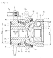
- Fig. 1 is a longitudinal section view showing a first embodiment of the bearing apparatus for a wheel of vehicle of the present invention
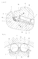
- Fig. 2 is a partially enlarged view of Fig. 1
- Fig. 3 is an enlarged cross sectional view taken along a line III-III of Fig. 2
- a term "outer side" (left hand side in the drawings) of the apparatus denotes a side which is positioned outside of the vehicle body
- a term “inner side” (right hand side in the drawings) of the apparatus denotes a side which is positioned inside of the body when the bearing apparatus is mounted on the vehicle body.
- This wheel bearing apparatus shown in Fig. 1 is a third generation type used for a driving wheel and comprises an inner member 1, an outer member 2, and double row tapered rollers 3, 3 for rollably contained between the inner and outer members 1, 2.
- the inner member 1 comprises the hub wheel 4 and an inner ring 5 press fitted on the hub wheel 4 with a predetermined interference.
- the hub wheel 4 is integrally formed with a wheel mounting flange 6 at its one end, one (outer side) tapered inner raceway surface 4a on the outer circumferential surface, a cylindrical portion 4b axially extending from the inner raceway surface 4a, and a serration (or spline) 4c on the inner circumferential surface.
- Hub bolts 6a are arranged on the wheel mounting flange 6 equidistantly along the periphery of the wheel mounting flange 6.
- the inner ring 5 is formed on its outer circumferential surface with the other (inner side) tapered inner raceway surface 5a and adapted to be press fitted on the cylindrical portion 4b of the hub wheel 4.
- the inner ring 5 and the tapered rollers 3 are made of high carbon chrome bearing steel such as SUJ 2 and hardened to their core by dipping quenching as having hardness of 58 ⁇ 64 HRC.
- No large flange for guiding rollers or small flange for holding rollers of the prior art is formed on both ends of the inner raceway surfaces 4a, 5a of the hub wheel 4 and the inner ring 5.
- large flanges 2b are integrally formed on the outer raceway surfaces 2a, 2a of the outer member 2 which will be described later.
- the hub wheel 4 is made of medium/high carbon steel including carbon of 0.40 ⁇ 0.80 % by weight such as S53C and hardened by high frequency induction quenching so that a region including the inner raceway surface 4a, a circular arc base 6b formed inner side of the wheel mounting flange 6 and the cylindrical portion 4b has surface hardness of 58 ⁇ 64 HRC. Accordingly wear resistance of the base 6b forming a seal land portion of the seal 8 is improved and the wheel mounting flange 6 has a sufficient mechanical strength against the rotary bending load applied thereto and the anti-fretting strength of the cylindrical portion 4b at a region press fitted by the inner ring 5 can be improved.
- the outer member 2 is integrally formed on its outer circumferential surface with a body mounting flange 2c to be mounted on a knuckle (not shown) of a vehicle and on its inner circumferential surface with tapered outer raceway surfaces 2a, 2a outwardly opened and arranged oppositely to the double row inner raceway surfaces 4a, 5a of the inner member 1. Double tapered rollers 3, 3 are contained between these outer and inner raceway surfaces and rollably held by cages 7, 7.
- the outer member 2 is made of medium/high carbon steel including carbon of 0.40 ⁇ 0.80 % by weight such as S53C and the double row outer raceway surfaces 2a, 2a are hardened by high frequency induction quenching so as to have a surface hardness of 58-64 HRC.
- Seals 8, 9 are mounted within annular spaces formed between the outer member 2 and the inner member 1. Concretely, seals 8, 9 are formed by a so-called pack seal in which the outer side seal 8 sliding contacts the base 6b of the wheel mounting flange 6 and the inner side seal 9 is mounted on the inner circumferential surface of the outer member 2 and on the outer circumferential surface of the inner ring 5. These seals 8, 9 prevent leakage of grease contained in the bearing and entering of rain water and dusts into the bearing from outside.
- the structure shown here is that of third generation bearing for a driving wheel, the present invention is not limited to use for a driving wheel and can be applied to use for a driven wheel if the bearing apparatus has a construction in which the inner raceway surfaces are formed on the hub wheel.
- the outer member 2 is integrally formed on the larger diameter end of the outer raceway surface 2a with the large flange 2b as shown in an enlarged view of Fig. 2 and the outer side seal 8 is fitted on the inner circumferential surface of the large flange 2b.
- the cages 7 are formed by injection molding of base thermoplastic resin such as PA (polyamide) 66 into which reinforcing material such as GF (glass fiber) is added. Each cage 7 is constructed as shown in Fig.
- the assembly of the bearing can be easily achieved only by inserting or fitting the posts 11 of the cage 7 between the adjacent rollers 3 from radially inward so that the rollers 3 are simultaneously fitted into the pockets 10, and then by inserting the hub wheel 4 and the inner ring 5 from both sides of the outer member 2 in which the taper rollers are assembled.
- the hub wheel 4 and the inner ring 5 from both sides of the outer member 2 in which the taper rollers are assembled.
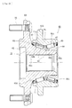
- Fig. 4 is a longitudinal section view showing a second embodiment of the bearing apparatus for a wheel of vehicle of the present invention
- Fig. 5 is a partially enlarged view of Fig. 4
- Fig. 6 is an explanatory view showing a method for assembling the bearing apparatus for a wheel of vehicle of the present invention.
- Same reference numerals are used herein for designating same parts as those having same functions used in the first embodiment.
- This wheel bearing apparatus is a fourth generation type and formed as a unit of an hub wheel 12, a double row rolling bearing 13 and a constant velocity universal joint 14.
- the double row rolling bearing 13 comprises an inner member 15, the outer member 2, and double row tapered rollers 3, 3 for rollably contained between the inner and outer members 15, 2.
- the inner member 15 comprises the hub wheel 12 and an outer joint member 16 fitted into the hub wheel 12 and connected thereto via plastic deformation of the outer joint member 16.
- the hub wheel 12 is integrally formed with a wheel mounting flange 6 at its one end, one (outer side) tapered inner raceway surface 4a on the outer circumferential surface, a cylindrical portion 12a axially extending from the inner raceway surface 4a.
- the hub wheel 12 is made of medium/high carbon steel including carbon of 0.40 ⁇ 0.80 % by weight such as S53C and hardened by high frequency induction quenching so that a region including the inner raceway surface 4a, the inner side base 6b inner side of the wheel mounting flange 6 and the cylindrical portion 12a has surface hardness of 58 ⁇ 64 HRC. Accordingly the hub wheel 12 has a sufficient mechanical strength against the rotary bending load applied to the wheel mounting flange 6.
- the inner circumferential surface of the hub wheel 12 is formed with an irregular portion 17 which is heat treated as having surface hardness of HRC 54 ⁇ 64. It is preferable to use as the heat treatment high frequency induction heating which can easily carry out local heating and setting of the depth of the hardened layer.
- the irregular portion 17 is formed as having a crisscross pattern knurl comprising an orthogonally crossed grooves formed by a plurality of independent annular grooves formed e.g. by turning and a plurality of axial grooves formed by broaching, or a crossing groove formed by mutually inclined spiral grooves.
- each tip projection of the irregular portion 17 is formed by a pointed configuration such as a pyramid.
- the constant velocity universal joint 14 comprises the outer joint member 16, a joint inner ring 18, a cage 19 and torque transmitting balls 20.
- the outer joint member 16 is made of medium carbon steel including carbon of 0.40 ⁇ 0.80 % by weight such as S53C and integrally formed by a cup shaped mouth portion 21, a shoulder 22 forming a bottom of the mouth portion 21, and a cylindrical shaft portion 23 axially extending from the shoulder 22.
- the shaft portion 23 is formed by a spigot portion 23a fitted in the hub wheel 12 via a predetermined radial gap and a fitting portion 23b at the end of the spigot portion 23a.
- An inner surface of the mouth portion 21 is formed with curved track grooves 21a and an outer surface of the joint inner ring 18 is formed with track grooves 18a corresponding to the track grooves 21a.
- the torque transmitting balls 20 are contained between the track grooves 21a, 18a via the cage19.
- An outer circumferential surface of the shoulder 22 is formed with an inner side tapered inner raceway surface 16c opposed to one of the double row outer raceway surface 2a, 2a.
- the track grooves 21a and a region including a seal fitted portion to which a seal 24 mentioned later sliding contacts, the inner raceway surface 16a and the shaft portion 23 are hardened by the high frequency induction heating as having a surface hardness of 58-64 HRC and the fitting portion 23b of the shaft portion 23 is kept as a no-quenched portion after being forged.
- a plurality of the double row tapered rollers 3, 3 are contained between the double row outer raceway surfaces 2a, 2a and the double row inner raceway surfaces 4a, 16a opposite to the double row outer raceway surfaces 2a, 2a and held freely rollably therein by the cages 7, 7.
- the seals 24, 24 are mounted on both ends of the outer member 2 and prevent leakage of grease contained in the bearing and entering of rain water and dusts into the bearing from outside.
- the double row rolling bearing 13 forms a so-called back-to-back double row tapered roller bearing in which smaller the distance of line of action of force applied to both raceway surfaces 2a, 4a and 2a, 16a from the axial center, larger the distance between the rollers in their axial direction.
- large flanges 2b for guiding the tapered rollers 3 are formed at larger side ends of the outer raceway surfaces 2a of the outer member 2 and no small flange for holding rollers and large flange for guiding rollers is formed at both side ends of the inner raceway surfaces 4a, 16a of the hub wheel 12 and the outer joint member 16.
- the posts 11 of the cages 7 are positioned radially inward the pitch circle diameter of the tapered rollers 3 and thus prevent the tapered rollers 3 from being fallen out from the cages 7.
- the seal 24 is formed as a so-called pack seal comprising a slinger 25 having press fitted on the base 6b of the wheel mounting flange and an annular sealing plate 26 a substantially "L" shaped cross section press fitted in the large flange 2b of the outer member 2 oppositely to the slinger 25 and having a sealing member.
- This enables to prevent the sealing plate 26 from being interfered by cage 7 and thus from being deformed or damaged.
- the slinger 25 is made of an austenitic stainless steel sheet (JIS SUS 304 etc.) or a preserved cold rolled sheet (JIS SPCC etc.) and formed as having a substantially "L" shaped cross section by press forming said sheet and comprises a cylindrical portion 25a fitted on the base 6b (shoulder 22) and a standing portion 25b extending radially outward from the cylindrical portion 25a.
- JIS SUS 304 etc. austenitic stainless steel sheet
- JIS SPCC etc. a preserved cold rolled sheet
- the sealing plate 26 comprises a metal core 26a fitted in the end of the outer member 2 and a sealing member 26b integrally adhered to the metal core 26a via vulcanized adhesion.
- the metal core 26a is made of an austenitic stainless steel sheet (JIS SUS 304 etc.) or a preserved cold rolled sheet (JIS SPCC etc.) and formed by press forming.
- the sealing member 26b comprises a pair of side lips 26c, 26d sliding contacting the standing portion 25b of the slinger 25 and a radial lip 26e sliding contacting the cylindrical portion 25a of the slinger 25.
- the cages 7 are elastically deformed and fitted in the outer member 2 from radially inward with the tapered rollers 3, 3 being arranged in rows on the outer raceway surfaces 2a, 2a of the outer member 2 and arranging the pockets 10 of the cages corresponding to the double row tapered rollers 3, 3.
- the sealing plates 26 forming the seal 24 are fitted within both ends of the outer member 2.
- slingers 25 forming seal 24 are press fitted respectively on the base 6b of the wheel mounting flange 6 and the shoulder 22 of the outer joint member 16 and then the hub wheel 12 and the outer joint member 16 are fitted in the outer member 2 along directions shown by arrows in Fig.
- This structure enables to eliminate necessity to control the amount of pre-load by fastening the outer joint member using a nut in the prior art and thus it is possible to reduce the weight and size of the bearing apparatus and increase the strength and durability of the hub wheel 12 and to keep the amount of pre-load for a long term.
- End caps 27, 28 are mounted respectively on openings of the hub wheel 12 and the hollow shaft portion 23 of the outer joint member 16 to prevent entering of rain water and dusts into the bearing from outside and leakage of grease contained in the bearing (see Fig. 4 ).
- the tapered rollers 3, 3 tend to rub the raceway surfaces along their generating lines during assembly of the bearing, it is difficult to keep a stable inside gap of the bearing during the radially enlarging and caulking step. That is, grease would be expelled from the line contacting region and cause metal-to-metal contact and thus increase the frictional coefficient in the contacting portions. Accordingly it is afraid that the tapered rollers 3, 3 would not smoothly move toward the large flanges 2b, 2b and thus would be assembled in a misaligned condition.
- the inside gap would be a positive gap when a negative gap has to be obtained and thus there would be caused a case in which a desirable pre-load cannot be applied. This would be further remarkable when the center line of each tapered roller 3 is inclined relative to its ordinal rotation axis, i.e. when a so-called skew is generated.
- the plastic deformation connection in the radially enlarging and caulking step is carried out with causing a relative swing motion (reciprocal motion) or a rotation (one way rotation) between the hub wheel 12 and outer joint member 16 and the outer member 2 in the present embodiment.
- the hub wheel 12 and the shaft portion 23 of the outer joint member 16 are united via plastic deformation by inserting the enlarging tool into the shaft portion 23 with the outer member 2 being reciprocated relative to the hub wheel 12 under a condition of supporting the hub wheel 12 on a top surface of a working bench.
- This enables the double row tapered rollers 3, 3 to smoothly slide on the raceway surfaces and to be stably aligned to the large flanges 2b, 2b. Accordingly a predetermined pre-load can be applied accurately.
- the hub wheel 12 and the outer joint member 16 are united via plastic deformation by deforming the shaft portion of the outer joint member radially outward
- Fig. 7 is a longitudinal section view showing a third embodiment of the bearing apparatus for a wheel of vehicle of the present invention. Same reference numerals are used herein for designating same parts as those having same functions used in the previous embodiments.
- This wheel bearing apparatus is formed as a unit of an hub wheel 29, a double row rolling bearing 30 and a constant velocity universal joint 31.
- a double row rolling bearing 30 comprises an outer member 32, an inner member 33, and double row tapered rollers 34, 35.
- the inner member 33 comprises the hub wheel 29 and an outer joint member 37 fitted into the hub wheel 29.
- the outer member 32 is made of medium/high carbon steel including carbon of 0.40 ⁇ 0.80 % by weight such as S53C and is integrally formed on its outer circumferential surface with a body mounting flange 32c and on its inner circumferential surface with tapered outer raceway surfaces 32a, 32b.
- the double row outer raceway surfaces 32a, 32b are hardened by high frequency induction quenching so as to have a surface hardness of 58 ⁇ 64 HRC.
- the hub wheel 29 is made of medium/high carbon steel including carbon of 0.40 ⁇ 0.80 % by weight such as S53C and is integrally formed with a wheel mounting flange 6 at its outer side end.
- a plurality of hub bolts 6a are mounted on the wheel mounting flange 6 equidistantly along the periphery thereof.
- the hub wheel 29 is formed on its outer circumferential surface with one (i.e. outer side) tapered inner raceway surface 29a arranged oppositely to one of the double row outer raceway surfaces 32a, 32b and a cylindrical portion 29b axially extending from said inner raceway surface 29a.
- the hub wheel 4 is hardened by high frequency induction quenching so that a region including a seal land portion 6b to which the outer side seal 36 sliding contacts, the inner raceway surface 29a and the cylindrical portion 29b has surface hardness of 58-64 HRC. Accordingly not only wear resistance of the base 6b forming the seal land portion of the outer side seal 36 is improved but the hub wheel 29 has a sufficient mechanical strength against the rotary bending load applied to the wheel mounting flange 6.
- the constant velocity universal joint 31 comprises the outer joint member 37, the joint inner ring 18, the cage 19 and torque transmitting balls 20.
- the outer joint member 37 is made of medium/high carbon steel including carbon of 0.40 ⁇ 0.80 % by weight such as S53C and integrally formed by a cup shaped mouth portion 21, shoulder 38 forming a bottom of the mouth portion 21, and a cylindrical shaft portion 23 axially extending from the shoulder 38.
- the shaft portion 23 is formed by a spigot portion 23a fitted into the cylindrical portion 29b of the hub wheel 29 via a predetermined radial gap and a fitting portion 23b at the end of the spigot portion 23a.
- An outer circumferential surface of the shoulder 38 is formed with the other (inner side) tapered inner raceway surface 37a opposed to the other of the double row outer raceway surface 32a, 32a.
- the track grooves 21a and a region including a seal fitted portion to which an inner side seal 24 sliding contacts, the inner raceway surface 37a and the shaft portion 23 are hardened by the high frequency induction heating as having a surface hardness of 58-64 HRC.
- a plurality of the double row tapered rollers 34, 35 are contained between the double row outer raceway surfaces 32a, 32b of the outer member 32 and the double row inner raceway surfaces 29a, 37a opposite to the double row outer raceway surfaces 32a, 32b and held freely rollably therein by the cages 39, 40.
- the seals 36, 24 are mounted on both ends of the outer member 32 and prevent leakage of grease contained in the bearing and entering of rain water and dusts into the bearing from outside.
- the double row rolling bearing 30 forms a so-called back-to-back double row tapered roller bearing in which smaller the distance of line of action of force applied to both raceway surfaces 32a, 29a and 32b, 37a from the axial center, larger the distance between the rollers in their axial direction.
- a pitch circle diameter PCDi of the inner side rolling elements 35 is larger than a pitch circle diameter PCDo of the outer side rolling elements 34. Since specifications of these rolling elements 34, 35 are same, the number of the inner side rolling elements 35 is larger than that of the outer side rolling elements 34.
- the specifications of the rolling elements 34, 35 denote the length of roller, the outer diameter of roller, the inclination angle of roller, and the radius of curvature of the larger end of roller.
- the pitch circle diameters PCDo and PCDi without changing the specifications such as the inclination angle of roller or the radius of curvature, the inclination angles of the inner side and outer side raceway surfaces have to be differentiated. In the present embodiment it is possible to avoid erroneous assembly, to reduce the manufacturing cost and to reliability of the bearing by setting the specifications of the double row rollers 34, 35.
- the diameter of the inner raceway surface 37a of the outer joint member 37 is larger than that of the inner raceway surface 29a of the hub wheel 29 in the inner member 33.
- the diameter of the inner side outer raceway surface 32b is larger than that of the outer side outer raceway surface 32a in the outer member 32.
- the inner side inner raceway surface 37a is directly formed on the outer circumferential surface of the shoulder 38 of the outer joint member 37, it is possible to set the pitch circle diameter PCDi of the inner side rollers 35 larger than the pitch circle diameter PCDo of the outer side rollers 34 and to set the number of the inner side rollers 35 larger than that of the outer side rollers 34. Accordingly it is possible to reduce the weight and size of the bearing apparatus and to extend the life of the bearing apparatus due to increase of the bearing rigidity of the inner side as compared with that of the outer side.
- the large flange for guiding the rolling elements (tapered rollers) 34, 35 is formed on the inner member 33 (i.e. the hub wheel 29 and the outer joint member 37), it may be possible to form the large flange on the outer member 32 similarly to the previous embodiments since the falling out of the rolling elements 34, 35 radially inward can be prevented by the cages 39, 40.
- the double row rolling elements i.e. tapered rollers are temporarily assembled on the double row outer raceway surfaces 32a, 32b of the outer member 32 via the cages 39, 40 and seals 36, 24 are mounted on the both ends of the outer member 32.
- the shaft portion 23 of the outer joint member 37 is inserted into the hub wheel 29 from the inner side until the shoulder 38 of the outer joint member 37 abuts the end face of the cylindrical portion 29b of the hub wheel 29.
- an expanding tool such as a mandrel is pushed into a bore of a fitting portion 23b of the shaft portion 23 to radially expand the fitting portion 23b in order to bite the outer circumferential surface of the fitting portion 23b into the irregular portions 17 of the hub wheel 29.
- the hub wheel 29 and the outer joint member 37 are integrally united via plastic deformation of the fitting portion 23b.
- the tapered rollers 34, 35 tend to rub the raceway surfaces along their generating lines during assembly of the bearing. Accordingly, lubricant such as grease would be expelled from the line contacting region and cause metal-to-metal contact and thus increase the frictional coefficient in the contacting portions. Thus it is afraid that the tapered rollers 34, 35 would not smoothly move toward the large flanges and therefore would be assembled in a misaligned condition.
- the inside gap would be a positive gap when a negative gap has to be obtained and thus there would be caused a case in which a desirable pre-load cannot be applied.
- the plastic deformation connection in the radially enlarging and caulking step is carried out with causing a relative swing motion (reciprocal motion) or a rotation (one way rotation) between the hub wheel 29 and outer joint member 37 and the outer member 32 in the present embodiment.
- the hub wheel 29 and the shaft portion 23 of the outer joint member 37 are united via plastic deformation by inserting the enlarging tool into the shaft portion 23 with the outer member 32 being reciprocated relative to the hub wheel 29 under a condition of supporting the hub wheel 29 on a top surface of a working bench.
- This enables the double row tapered rollers 34, 35 to smoothly slide on the raceway surfaces and to be stably aligned to the large flanges. Accordingly a predetermined pre-load can be applied accurately.
- the hub wheel 29 and the outer joint member 37 are united via plastic deformation by deforming the shaft portion of the outer joint member radially outward
- Fig. 8 is a longitudinal section view showing a fourth embodiment of the bearing apparatus for a wheel of vehicle of the present invention. Since the present embodiment is different from the third embodiment ( Fig. 7 ) only in the structure of the inner side bearing array, same reference numerals are used herein for designating same parts as those having same functions used in the previous embodiments and detailed explanation thereof will be omitted.
- This wheel bearing apparatus is formed as a unit of a hub wheel 29, a double row rolling bearing 40 and a constant velocity universal joint 41.
- a double row rolling bearing 40 comprises an outer member 42, an inner member 43, and double row rolling elements 34, 44.
- the inner member 43 comprises the hub wheel 29 and an outer joint member 45 fitted into the hub wheel 29.
- the outer member 42 is made of medium/high carbon steel including carbon of 0.40 ⁇ 0.80 % by weight such as S53C and is integrally formed on its outer circumferential surface with a body mounting flange 32c and on its inner circumferential surface with an outer side tapered outer raceway surface 32a and an inner side circular arc outer raceway surface 42a.
- These double row outer raceway surfaces 32a, 42a are hardened by high frequency induction quenching so as to have a surface hardness of 58-64 HRC.
- the outer joint member 45 of the constant velocity universal joint 41 is made of medium/high carbon steel including carbon of 0.40 ⁇ 0.80 % by weight such as S53C and integrally formed with a cup shaped mouth portion 21, a shoulder 46 forming a bottom of the mouth portion 21, and a cylindrical shaft portion 23 axially extending from the shoulder 46.
- An inner side inner raceway surfaces 45a is directly formed on the outer circumferential surface of the shoulder 46 oppositely to the outer raceway surface 42a of the outer member 42.
- a plurality of rolling elements 34, 44 are contained between the double row outer raceway surfaces 32a, 42a of the outer member 42 and the double row inner raceway surfaces 29a, 45a of the inner member 43 and held freely rollably by cages 39, 47.
- the pitch circle diameter PCDi of the inner side rolling elements (balls) 44 is set larger than the pitch circle diameter PCDo of the outer side rolling elements (tapered rollers) 34. Due to the difference of the pitch circle diameters PCDo, PCDi, the number of the inner side rolling elements 44 may be set larger than that of the outer side rolling elements 34.
- the inner side bearing array is formed by the rolling elements comprising balls and the inner side inner raceway surfaces 45a is directly formed on the outer circumferential surface of the shoulder 46 of the outer joint member 45, it is possible to set the pitch circle diameter PCDi of the inner side rolling elements 44 larger than the pitch circle diameter PCDo of the outer side rolling elements 34 and the number of the inner side rolling elements 44 is set larger than that of the outer side rolling elements 34. Accordingly it is possible to further reduce the axial size of the bearing apparatus with keeping the loading capacity of the double row bearing arrays or balance of the rigidity of the bearing apparatus.
- Fig. 9 is a longitudinal section view showing a fifth embodiment of the bearing apparatus for a wheel of vehicle of the present invention. Since the present embodiment is different from the fourth embodiment ( Fig. 8 ) only in the structure of the left and right bearing arrays, same reference numerals are used herein for designating same parts as those having same functions used in the previous embodiments and detailed explanation thereof will be omitted.
- This wheel bearing apparatus is formed as a unit of a hub wheel 48, a double row rolling bearing 49 and a constant velocity universal joint 31.
- a double row rolling bearing 49 comprises an outer member 50, an inner member 51, and double row rolling elements 52, 35.
- the inner member 51 comprises the hub wheel 48 and an outer joint member 37 fitted into the hub wheel 48.
- the outer member 50 is made of medium/high carbon steel including carbon of 0.40 ⁇ 0.80 % by weight such as S53C and is integrally formed on its outer circumferential surface with a body mounting flange 32c and on its inner circumferential surface with an outer side circular arc outer raceway surface 50a and an inner side tapered outer raceway surface 32a.
- These double row outer raceway surfaces 50a, 32a are hardened by high frequency induction quenching so as to have a surface hardness of 58-64 HRC.
- the hub wheel 48 is made of medium/high carbon steel including carbon of 0.40 ⁇ 0.80 % by weight such as S53C and is formed with one (outer side) circular arc inner raceway surface 48a and a cylindrical portion 48b axially extending from the inner raceway surface 48a.
- the hub wheel 48 is hardened by high frequency induction quenching so that a region including the base 6b to which the outer side seal 36 sliding contacts, inner raceway surface 48a and the cylindrical portion has surface hardness of 58-64 HRC.
- Double row rolling elements 52, 35 are contained between the double row outer raceway surfaces 50a, 32b of the outer member 50 and the double row inner raceway surfaces 48a, 37a opposite to the double row outer raceway surfaces 50a, 32b and held freely rollably therein by the cages 53, 40.
- the pitch circle diameter PCDo of the outer side rolling elements (balls) 52 is set larger than the pitch circle diameter PCDi of the inner side rolling elements (tapered rollers) 35. Due to the difference of the pitch circle diameters PCDo, PCDi, the number of the outer side rolling elements 52 may be set larger than that of the outer side rolling elements 35.
- the outer side bearing array is formed by the rolling elements comprising balls 52 and the pitch circle diameter PCDo of the outer side rolling elements 52 is set larger than the pitch circle diameter PCDi of the inner side rolling elements 35 and the number of the outer side rolling elements 52 is set larger than that of the inner side rolling elements 35, it is possible to reduce the axial size of the bearing apparatus with keeping the loading capacity of the double row bearing arrays or balance of the rigidity of the bearing apparatus.
- the bearing apparatus for a wheel of vehicle of the present invention can be applied to the wheel bearing apparatus of third or fourth generation in which the inner raceway surface is directly formed on the outer circumferential surface of the hub wheel.
Landscapes
- Engineering & Computer Science (AREA)
- General Engineering & Computer Science (AREA)
- Mechanical Engineering (AREA)
- Rolling Contact Bearings (AREA)
Abstract
Description
- The present invention relates to a bearing apparatus having a tapered roller bearing for freely rotatably supporting a wheel of vehicle, and more particularly to a bearing apparatus for a wheel of vehicle intended to reduce the weight and size of the wheel bearing apparatus.
- In usual, the bearing apparatus for a wheel of vehicle is adapted to freely rotatably support a hub wheel for mounting the wheel via a rolling bearing and it is adopted an inner ring rotation type for a driving wheel and both inner ring rotation and outer ring rotation types for a driven wheel. Double row angular ball bearings are widely used in such a bearing apparatus from reasons that it has a desirable bearing rigidity, high durability against misalignment, and small rotation torque required for fuel consumption. On the contrary double row tapered roller bearings are widely used for off-road vehicles, trucks and heavy duty vehicles.
- The bearing apparatus for a wheel of vehicle is broadly classified to a structure of first generation in which a wheel bearing of double row angular contact ball bearing is fitted between a knuckle forming part of a suspension and a hub wheel, a structure of second generation in which a body mounting flange or a wheel mounting flange is directly formed on the outer circumferential surface of an outer member, a structure of third generation in which one of the inner raceway surfaces is directly formed on the outer circumferential surface of the hub wheel, and a structure of fourth generation in which the inner raceway surfaces are directly formed on the outer circumferential surfaces of the hub wheel and the constant velocity universal joint.
- In such a case since the bearing apparatus for a wheel of vehicle having a double row tapered roller bearing apparatus is usually used in heavy duty vehicles such as trucks it is not so much required to reduce the weight and size of the bearing apparatus, and thus it is the present situation that development of the double row tapered roller bearing apparatus has been stayed yet in use for the second generation structure as compared with the development of the double row angular ball bearing. However since demand for wagon type vehicles has increased in recently and thus multiple functions of vehicles are desired it has been desired to reduce the weight and size also in the double row tapered roller bearing apparatus having a large load capacity.
- One example of the wheel bearing apparatus of the prior art is shown in
Fig. 10 . The bearing apparatus for a wheel ofvehicle 60 is formed by a double row tapered roller bearing comprising anouter member 61 integrally formed on its outer circumferential surface with abody mounting flange 61b to be mounted on a knuckle (not shown) of a vehicle and on its inner circumferential surface with double rowouter raceway surfaces inner member 65 integrally formed on its outer circumferential surface with double rowinner raceway surfaces outer raceway surfaces tapered rollers outer raceway surfaces inner raceway surfaces cages rollers - The
inner member 65 comprises ahub wheel 62 having awheel mounting flange 63 formed integrally therewith at one end thereof, oneinner raceway surface 62a formed on the outer circumferential surface thereof oppositely to one of the double rowouter raceway surfaces cylindrical portion 62b axially extending from said oneinner raceway surface 62a, and aserration 62c for torque transmission formed on the inner circumferential surface, and comprises aninner ring 64 press fitted on thecylindrical portion 62b and formed on its outer circumferential surface with the otherinner raceway surface 64a oppositely to the other of the double rowouter raceway surfaces inner member 65 forms the wheel bearing apparatus of the third generation structure for driving a driving wheel. - In
addition hub bolts 70 are adapted to be mounted on thewheel mounting flange 63 equidistantly along its outer periphery. Furthermoreseals outer member 61 and theinner member 65 to prevent leakage of grease contained within the bearing apparatus and entering of rain water or dusts into the bearing apparatus from the outside. - In such a structure
large flanges tapered rollers 66 are formed at larger side ends of theinner raceway surfaces hub wheel 62 and theinner ring 64 respectively. However any small flange is not formed at smaller side ends of theinner raceway surfaces cages 67 keep thetapered rollers 66 in a falling out preventing condition withinpockets 71 in a preassembling condition. That is, as shown inFig. 11 thecage 67 is formed of synthetic resin by injection molding andposts 72 between mutuallyadjacent pockets portion 72a is tapered convergent toward radially inward and a radiallyinward projection 72b is integrally formed therewith. - The width of a
pocket 71 between the radiallyoutward portions tapered roller 66 cannot fall out radially outward with it being contacted by the tapered surfaces of theposts 72. On the other hand the width "W" between the radiallyinward projections tapered roller 66 such that eachtapered roller 66 can be press fitted in to thepocket 71 from radially inward and it cannot inadvertently fall out radially inward with it being contacted by the radiallyinward projections 72b as shown by a two-dot chain line. Such a structure of thecage 67 enables not only to reduce the number of parts and manufacturing cost but to make easy the assembly of the bearing apparatus in an automatic assembling apparatus as well as to eliminate assembling steps of the bearing apparatus (see Japanese Laid-open Patent Publication No.44322/1999 - In such a
wheel bearing apparatus 60 of the prior art thecages 67 are formed so that the radiallyinward projections 72b of them prevent inadvertent falling out of thetapered rollers 66 radially inward with therollers 66 being contacted by the radiallyinward projections 72b. However if the width "W" between the mutuallyadjacent projections rollers 66 into thepockets 71. Accordingly the entrance width "W" of balls should be strictly formed at the predetermined dimension without dimensional variation in order to surely prevent the falling out of thetapered rollers 66. However ability of injection molding of thecages 67 to achieve strict dimensional accuracy of the width "W" in mass production is limited. In addition since thecage 67 is a type in which therollers 66 can be inserted into thepockets 71 by elastically deforming the radiallyinward projections 72b, it is difficult to simultaneously insert therollers 66 into thepockets 71 and the number of assembling steps is increased. Thus it is difficult to achieve easiness of assembly in an automatic assembling apparatus as well as to greatly reduce the assembling steps. - It is, therefore, an object of the present invention to provide a bearing apparatus for a wheel of vehicle which can achieve easiness of assembly in an automatic assembling apparatus as well as to greatly reduce the assembling steps.
- Also it is an object to provide a bearing apparatus for a wheel of vehicle which can improve sealing ability of the bearing apparatus.
- In addition it is an object to provide a bearing apparatus for a wheel of vehicle which can reduce the weight and the size and increase the rigidity of the bearing apparatus.
- For achieving the object of the present invention, there is provided according to the present invention a bearing apparatus for a wheel of vehicle of a type of back-to-back double row tapered roller bearing comprising: an outer member integrally formed on its outer surface with a body mounting flange to be mounted on a suspension apparatus of vehicle and also formed on its inner surface with double row outer raceway surfaces tapered open respectively axially inward and outward; an inner member including a hub wheel and an inner ring or an outer joint member of a constant velocity universal joint, the hub wheel having a wheel mounting flange integrally formed therewith at one end thereof and one inner raceway surface formed on the outer circumferential surface thereof arranged oppositely to one of the double row outer raceway surfaces and a cylindrical portion axially extending from said inner raceway surface, said inner ring an inner ring or the outer joint member of a constant velocity universal joint being press fitted on the cylindrical portion and formed on its outer circumferential surface with the other inner raceway surface arranged opposite to the other raceway surface of the double row outer raceway surfaces; double row tapered rollers freely rollably held between the outer and inner raceway surfaces by cages; and seals arranged in annular openings formed by the outer and inner members at both ends thereof characterized in that said cages are formed of synthetic resin by injection molding; that posts between pockets of the cages are arranged to be positioned radially inward the pitch circle diameter of the tapered rollers; and that the width of an opening of radially inward of each pocket is set so that each tapered roller is held within the pocket with contacting tapered surfaces of the posts opened radially outward so as not to be fallen out radially inward (claiml).
- According to the bearing apparatus for a wheel of vehicle of a type of back-to-back double row tapered roller bearing having a structure for the third or fourth generation type comprising an outer member integrally formed on its outer surface with a body mounting flange and on its inner surface with double row outer raceway surfaces; an inner member including a hub wheel having a wheel mounting flange integrally formed therewith at one end thereof and one inner raceway surface formed on the outer circumferential surface or an outer joint member of a constant velocity universal joint; double row tapered rollers freely rollably held between the outer and inner raceway surfaces by cages; and seals arranged in annular openings formed by the outer and inner members at both ends thereof, since said cages are formed of synthetic resin by injection molding, posts between pockets of the cages are arranged to be positioned radially inward the pitch circle diameter of the tapered rollers, and the width of an opening of radially inward of each pocket is set so that each tapered roller is held within the pocket with contacting tapered surfaces of the posts opened radially outward so as not to be fallen out radially inward, it is possible to surely prevent falling out of the tapered rollers from the cages by holding the tapered rollers by the outer raceway surfaces of the outer member and the cages without strict control of the dimensionnal accuracy of the cages and accordingly it is also possible to achieve easiness of assembly in an automatic assembling apparatus as well as to greatly reduce the assembling steps.
- There is also provided a bearing apparatus for a wheel of vehicle of a type of back-to-back double row tapered roller bearing comprising: an outer member integrally formed on its outer surface with a body mounting flange to be mounted on a suspension apparatus of vehicle and also formed on its inner surface with double row outer raceway surfaces tapered open respectively axially inward and outward; an inner member including a hub wheel and an inner ring or an outer joint member of a constant velocity universal joint, the hub wheel having a wheel mounting flange integrally formed therewith at one end thereof and one inner raceway surface formed on the outer circumferential surface thereof arranged oppositely to one of the double row outer raceway surfaces and a cylindrical portion axially extending from said inner raceway surface, said inner ring being press fitted on the cylindrical portion and formed on its outer circumferential surface with the other inner raceway surface arranged opposite to the other raceway surface of the double row outer raceway surfaces; double row tapered rollers freely rollably held between the outer and inner raceway surfaces by cages; and seals arranged in annular openings formed by the outer and inner members at both ends thereof characterized in that said cages are formed of synthetic resin by injection molding, that the tapered rollers are held within the pocket so as not to be fallen out radially inward, and that larger flanges for guiding the tapered rollers are integrally formed on larger diameter sides of the outer raceway surfaces of the outer member (claim 2).
- According to the bearing apparatus for a wheel of vehicle of a type of back-to-back double row tapered roller bearing having a structure for the third or fourth generation type comprising an outer member integrally formed on its outer surface with a body mounting flange and on its inner surface with double row outer raceway surfaces; an inner member including a hub wheel having a wheel mounting flange integrally formed therewith at one end thereof and one inner raceway surface formed on the outer circumferential surface or an outer joint member of a constant velocity universal joint; double row tapered rollers freely rollably held between the outer and inner raceway surfaces by cages; and seals arranged in annular openings formed by the outer and inner members at both ends thereof, since said cages are formed of synthetic resin by injection molding, the tapered rollers are held within the pocket so as not to be fallen out radially inward, and larger flanges for guiding the tapered rollers are integrally formed on larger diameter sides of the outer raceway surfaces of the outer member, it is possible to surely prevent falling out of the tapered rollers from the cages during assembly of the bearing apparatus and it is also possible to prevent the seals from being interfered by movement of the cages under a condition in which the roller assembly is inserted into the outer member. Accordingly it is possible to provide a wheel bearing apparatus which can improve the easiness of assembly of the bearing apparatus and the sealing ability.
- Further according to the present invention there is provided a bearing apparatus for a wheel of vehicle formed as a unit of a hub wheel, a rolling bearing and a constant velocity universal joint comprising: an outer member formed on its inner surface with double row outer raceway surfaces; an inner member including a hub wheel and an outer joint member, the hub wheel having a wheel mounting flange integrally formed therewith at one end thereof and one inner raceway surface formed on the outer circumferential surface thereof arranged oppositely to one of the double row outer raceway surfaces and a cylindrical portion axially extending from said inner raceway surface, said outer joint member fitted into the hub wheel and formed on its outer circumferential surface with the other inner raceway surface arranged opposite to the other raceway surface of the double row outer raceway surfaces and having a shaft portion axially extending from said other inner raceway surface; and double row rolling elements freely rollably held between the outer and inner raceway surfaces characterized in that a pitch circle diameter of outer side rolling elements of the double row rolling elements is different from that of inner side rolling elements of the double row rolling elements; and that the number of the rolling elements in the larger pitch circle diameter is set larger than that of the rolling elements in the smaller pitch circle diameter (claim 3). Accordingly it is possible to provide a wheel bearing apparatus which can increase the rigidity and also reduce the weight and size of the wheel bearing apparatus.
- In the present invention it is preferable that the inner member comprises the hub wheel and the outer joint member fitted into the hub wheel; that the outer joint member is integrally formed of a cup-shaped mouth portion, a shoulder portion on which outer circumferential surface said other inner raceway surface is directly formed, and a shaft portion axially extending from the shoulder portion, and that the hub wheel and the outer joint member are united by plastically deforming a hollow end of the shaft portion and caulking it on the hub wheel (claim 4). According to such a structure since the hub wheel and the outer joint member are united via plastically deformed connection, it is possible to eliminate the pre-load amount by adjusting fastening amount of nut as a conventional manner. Thus it is possible to maintain the pre-load amount for a long term and to increase the strength and durability of the hub wheel.
- It is also preferable that the hub wheel and the outer joint member are united by expanding radially outward the hollow end of the shaft portion of the outer joint member and biting it into a hardened irregular portion formed on an inner circumferential surface of the hub wheel (claim 5). This structure enables to further reduce the weight and size of the bearing apparatus due to the plastically deformed connection between the hub wheel and the outer joint member.
- It is preferable that the inner member comprises the hub wheel and the inner ring press fitted on the cylindrical portion of the hub wheel via a predetermined interference, and that an inner side base portion of the wheel mounting flange is rounded and its surface on which the seal is directly contact is hardened (claim 6). Such a structure enables to reduce the size of the bearing apparatus and to obtain a sufficient mechanical strength against the rotary bending load applied to the wheel mounting flange.
- It is also preferable that at least an inner side seal comprises a slinger press fitted onto the inner member, and an annular sealing plate including a metal core press fitted into the outer member and a sealing member integrally adhered to the metal core via vulcanized adhesion, and that each of the slinger and the metal core has a substantially "L" shaped cross section and they are arranged oppositely toward each other so that the sealing member slidingly contacts the slinger (claim 7). This structure enables to keep a high sealing ability for a long term.
- It is preferable that at least the rolling elements of the smaller pitch circle diameter of the double row rolling elements are tapered rollers (claim 8). This structure enables to keep a high rigidity of the wheel bearing apparatus.
- It is preferable that the double row rolling elements are tapered rollers each having same specifications (claim 9). This enables to eliminate erroneous assembly of the tapered rollers and thus to reduce the manufacturing cost and to improve the reliability of the bearing apparatus.
- It is also possible that the rolling elements of the larger pitch circle diameter of the double row rolling elements are balls (claim 10). This enables to further reduce the axial size of the wheel bearing apparatus with keeping balance of the loading capacity or the rigidity of the double bearing rows.
- The best mode for carrying out the present invention is a bearing apparatus for a wheel of vehicle of a type of back-to-back double row tapered roller bearing comprising: an outer member integrally formed on its outer surface with a body mounting flange to be mounted on a suspension apparatus of vehicle and also formed on its inner surface with double row outer raceway surfaces tapered open respectively axially inward and outward; an inner member including a hub wheel and an outer joint member of a constant velocity universal joint, the hub wheel having a wheel mounting flange integrally formed therewith at one end thereof and one inner raceway surface formed on the outer circumferential surface thereof arranged oppositely to one of the double row outer raceway surfaces and a cylindrical portion axially extending from said inner raceway surface, said outer joint member of the constant velocity universal joint being press fitted on the cylindrical portion and formed on its outer circumferential surface with the other inner raceway surface arranged opposite to the other raceway surface of the double row outer raceway surfaces; double row tapered rollers freely rollably held between the outer and inner raceway surfaces by cages; and seals arranged in annular openings formed by the outer and inner members at both ends thereof characterized in that the outer joint member is formed of a shoulder portion on which outer circumferential surface said other inner raceway surface is directly formed and of a cylindrical shaft portion axially extending from the shoulder portion, that the hub wheel and the outer joint member are united by expanding radially outward the hollow end of the shaft portion of the outer joint member and biting it into a hardened irregular portion formed on an inner circumferential surface of the hub wheel, that said cages are formed of synthetic resin by injection molding, that posts between pockets of the cages are arranged to be positioned radially inward the pitch circle diameter of the tapered rollers; and that the width of an opening of radially inward of each pocket is set so that each tapered roller is held within the pocket with contacting tapered surfaces of the posts opened radially outward so as not to be fallen out radially inward.
- Preferable embodiments of the present invention will be hereinafter described with reference to the drawings.
Fig. 1 is a longitudinal section view showing a first embodiment of the bearing apparatus for a wheel of vehicle of the present invention,Fig. 2 is a partially enlarged view ofFig. 1 , andFig. 3 is an enlarged cross sectional view taken along a line III-III ofFig. 2 . In the description below, a term "outer side" (left hand side in the drawings) of the apparatus denotes a side which is positioned outside of the vehicle body and a term "inner side" (right hand side in the drawings) of the apparatus denotes a side which is positioned inside of the body when the bearing apparatus is mounted on the vehicle body. - This wheel bearing apparatus shown in
Fig. 1 is a third generation type used for a driving wheel and comprises aninner member 1, anouter member 2, and double rowtapered rollers outer members inner member 1 comprises thehub wheel 4 and aninner ring 5 press fitted on thehub wheel 4 with a predetermined interference. - The
hub wheel 4 is integrally formed with awheel mounting flange 6 at its one end, one (outer side) taperedinner raceway surface 4a on the outer circumferential surface, acylindrical portion 4b axially extending from theinner raceway surface 4a, and a serration (or spline) 4c on the inner circumferential surface.Hub bolts 6a are arranged on thewheel mounting flange 6 equidistantly along the periphery of thewheel mounting flange 6. Theinner ring 5 is formed on its outer circumferential surface with the other (inner side) taperedinner raceway surface 5a and adapted to be press fitted on thecylindrical portion 4b of thehub wheel 4. Theinner ring 5 and the taperedrollers 3 are made of high carbon chrome bearing steel such asSUJ 2 and hardened to their core by dipping quenching as having hardness of 58□64 HRC. No large flange for guiding rollers or small flange for holding rollers of the prior art is formed on both ends of theinner raceway surfaces hub wheel 4 and theinner ring 5. In steadlarge flanges 2b are integrally formed on theouter raceway surfaces outer member 2 which will be described later. - The
hub wheel 4 is made of medium/high carbon steel including carbon of 0.40~0.80 % by weight such as S53C and hardened by high frequency induction quenching so that a region including theinner raceway surface 4a, acircular arc base 6b formed inner side of thewheel mounting flange 6 and thecylindrical portion 4b has surface hardness of 58~64 HRC. Accordingly wear resistance of thebase 6b forming a seal land portion of theseal 8 is improved and thewheel mounting flange 6 has a sufficient mechanical strength against the rotary bending load applied thereto and the anti-fretting strength of thecylindrical portion 4b at a region press fitted by theinner ring 5 can be improved. - The
outer member 2 is integrally formed on its outer circumferential surface with abody mounting flange 2c to be mounted on a knuckle (not shown) of a vehicle and on its inner circumferential surface with taperedouter raceway surfaces inner raceway surfaces inner member 1. Doubletapered rollers cages outer member 2 is made of medium/high carbon steel including carbon of 0.40~0.80 % by weight such as S53C and the double rowouter raceway surfaces -
Seals outer member 2 and theinner member 1. Concretely, seals 8, 9 are formed by a so-called pack seal in which theouter side seal 8 sliding contacts thebase 6b of thewheel mounting flange 6 and theinner side seal 9 is mounted on the inner circumferential surface of theouter member 2 and on the outer circumferential surface of theinner ring 5. Theseseals - According to the first embodiment of the present invention the
outer member 2 is integrally formed on the larger diameter end of theouter raceway surface 2a with thelarge flange 2b as shown in an enlarged view ofFig. 2 and theouter side seal 8 is fitted on the inner circumferential surface of thelarge flange 2b. Thecages 7 are formed by injection molding of base thermoplastic resin such as PA (polyamide) 66 into which reinforcing material such as GF (glass fiber) is added. Eachcage 7 is constructed as shown inFig. 3 so that theposts 11 between mutuallyadjacent pockets cage 7 are arranged to be positioned radially inward the pitch circle diameter (PCD) of the taperedrollers 3 and that the width "W" of an opening of radially inward of eachpocket 10 is set so that eachtapered roller 3 is held within the pocket with contacting tapered surfaces of theposts 11 opened radially outward so as not to be fallen out radially inward. Accordingly this surely makes it possible to prevent the taperedrollers 3 from being fallen out from thecages 7 by holding therollers 3 with theouter raceway surfaces 2a of theouter member 2 without strictly controlling the dimensional accuracy of thecages 7. - The assembly of the bearing can be easily achieved only by inserting or fitting the
posts 11 of thecage 7 between theadjacent rollers 3 from radially inward so that therollers 3 are simultaneously fitted into thepockets 10, and then by inserting thehub wheel 4 and theinner ring 5 from both sides of theouter member 2 in which the taper rollers are assembled. Thus it is possible to achieve easy assembly in an automatic assembling apparatus and to substantially reduce the assembling steps. - In addition since the
large flange 2b for guiding therollers 3 is formed on the larger diameter side of theouter raceway surface 2a of theouter member 2, thecage 7 cannot axially move toward theseal 8 as in the prior art under a condition in which the taperedrollers 3 are assembled in theouter member 2. Thus it is possible to prevent theseal 8 from being interfered by thecage 7 and accordingly from being deformed or damaged and thus detracted from the sealing ability. -
Fig. 4 is a longitudinal section view showing a second embodiment of the bearing apparatus for a wheel of vehicle of the present invention,Fig. 5 is a partially enlarged view ofFig. 4 , andFig. 6 is an explanatory view showing a method for assembling the bearing apparatus for a wheel of vehicle of the present invention. Same reference numerals are used herein for designating same parts as those having same functions used in the first embodiment. - This wheel bearing apparatus is a fourth generation type and formed as a unit of an
hub wheel 12, a doublerow rolling bearing 13 and a constant velocityuniversal joint 14. The doublerow rolling bearing 13 comprises aninner member 15, theouter member 2, and double rowtapered rollers outer members inner member 15 comprises thehub wheel 12 and an outerjoint member 16 fitted into thehub wheel 12 and connected thereto via plastic deformation of the outerjoint member 16. - The
hub wheel 12 is integrally formed with awheel mounting flange 6 at its one end, one (outer side) taperedinner raceway surface 4a on the outer circumferential surface, acylindrical portion 12a axially extending from theinner raceway surface 4a. Thehub wheel 12 is made of medium/high carbon steel including carbon of 0.40~0.80 % by weight such as S53C and hardened by high frequency induction quenching so that a region including theinner raceway surface 4a, theinner side base 6b inner side of thewheel mounting flange 6 and thecylindrical portion 12a has surface hardness of 58□64 HRC. Accordingly thehub wheel 12 has a sufficient mechanical strength against the rotary bending load applied to thewheel mounting flange 6. - The inner circumferential surface of the
hub wheel 12 is formed with anirregular portion 17 which is heat treated as having surface hardness of HRC 54~64. It is preferable to use as the heat treatment high frequency induction heating which can easily carry out local heating and setting of the depth of the hardened layer. Theirregular portion 17 is formed as having a crisscross pattern knurl comprising an orthogonally crossed grooves formed by a plurality of independent annular grooves formed e.g. by turning and a plurality of axial grooves formed by broaching, or a crossing groove formed by mutually inclined spiral grooves. Preferably each tip projection of theirregular portion 17 is formed by a pointed configuration such as a pyramid. - The constant velocity
universal joint 14 comprises the outerjoint member 16, a jointinner ring 18, acage 19 andtorque transmitting balls 20. The outerjoint member 16 is made of medium carbon steel including carbon of 0.40~0.80 % by weight such as S53C and integrally formed by a cup shapedmouth portion 21, ashoulder 22 forming a bottom of themouth portion 21, and acylindrical shaft portion 23 axially extending from theshoulder 22. Theshaft portion 23 is formed by aspigot portion 23a fitted in thehub wheel 12 via a predetermined radial gap and afitting portion 23b at the end of thespigot portion 23a. - An inner surface of the
mouth portion 21 is formed withcurved track grooves 21a and an outer surface of the jointinner ring 18 is formed withtrack grooves 18a corresponding to thetrack grooves 21a. Thetorque transmitting balls 20 are contained between thetrack grooves shoulder 22 is formed with an inner side tapered inner raceway surface 16c opposed to one of the double rowouter raceway surface track grooves 21a and a region including a seal fitted portion to which aseal 24 mentioned later sliding contacts, theinner raceway surface 16a and theshaft portion 23 are hardened by the high frequency induction heating as having a surface hardness of 58-64 HRC and thefitting portion 23b of theshaft portion 23 is kept as a no-quenched portion after being forged. - A plurality of the double row
tapered rollers outer raceway surfaces inner raceway surfaces outer raceway surfaces cages seals outer member 2 and prevent leakage of grease contained in the bearing and entering of rain water and dusts into the bearing from outside. The doublerow rolling bearing 13 forms a so-called back-to-back double row tapered roller bearing in which smaller the distance of line of action of force applied to bothraceway surfaces - Similarly to the first embodiment
large flanges 2b for guiding the taperedrollers 3 are formed at larger side ends of theouter raceway surfaces 2a of theouter member 2 and no small flange for holding rollers and large flange for guiding rollers is formed at both side ends of theinner raceway surfaces hub wheel 12 and the outerjoint member 16. And theposts 11 of thecages 7 are positioned radially inward the pitch circle diameter of the taperedrollers 3 and thus prevent the taperedrollers 3 from being fallen out from thecages 7. - As shown in an enlarged view of
Fig. 5 theseal 24 is formed as a so-called pack seal comprising aslinger 25 having press fitted on thebase 6b of the wheel mounting flange and anannular sealing plate 26 a substantially "L" shaped cross section press fitted in thelarge flange 2b of theouter member 2 oppositely to theslinger 25 and having a sealing member. This enables to prevent the sealingplate 26 from being interfered bycage 7 and thus from being deformed or damaged. - The
slinger 25 is made of an austenitic stainless steel sheet (JIS SUS 304 etc.) or a preserved cold rolled sheet (JIS SPCC etc.) and formed as having a substantially "L" shaped cross section by press forming said sheet and comprises acylindrical portion 25a fitted on thebase 6b (shoulder 22) and a standingportion 25b extending radially outward from thecylindrical portion 25a. - On the other hand the sealing
plate 26 comprises ametal core 26a fitted in the end of theouter member 2 and a sealingmember 26b integrally adhered to themetal core 26a via vulcanized adhesion. Themetal core 26a is made of an austenitic stainless steel sheet (JIS SUS 304 etc.) or a preserved cold rolled sheet (JIS SPCC etc.) and formed by press forming. The sealingmember 26b comprises a pair ofside lips portion 25b of theslinger 25 and aradial lip 26e sliding contacting thecylindrical portion 25a of theslinger 25. - Then a method for assembling the wheel bearing apparatus of the present embodiment will be described with reference to
Fig. 6 . Firstly thecages 7 are elastically deformed and fitted in theouter member 2 from radially inward with the taperedrollers outer raceway surfaces outer member 2 and arranging thepockets 10 of the cages corresponding to the double rowtapered rollers plates 26 forming theseal 24 are fitted within both ends of theouter member 2. Then slingers 25 formingseal 24 are press fitted respectively on thebase 6b of thewheel mounting flange 6 and theshoulder 22 of the outerjoint member 16 and then thehub wheel 12 and the outerjoint member 16 are fitted in theouter member 2 along directions shown by arrows inFig. 6 . Then theshaft portion 23 of the outerjoint member 16 is fitted in thehub wheel 12 until the end face of thecylindrical portion 12a of thehub wheel 12 abuts theshoulder 22 of the outerjoint member 16. Finally an expanding tool such as a mandrel is pushed into a bore of afitting portion 23b of theshaft portion 23 to radially expand thefitting portion 23b in order to bite the outer circumferential surface of thefitting portion 23b into theirregular portions 17 of thehub wheel 12. Thus thehub wheel 12 and the outerjoint member 16 are integrally united via plastic deformation of thefitting portion 23b. - This structure enables to eliminate necessity to control the amount of pre-load by fastening the outer joint member using a nut in the prior art and thus it is possible to reduce the weight and size of the bearing apparatus and increase the strength and durability of the
hub wheel 12 and to keep the amount of pre-load for a long term. End caps 27, 28 are mounted respectively on openings of thehub wheel 12 and thehollow shaft portion 23 of the outerjoint member 16 to prevent entering of rain water and dusts into the bearing from outside and leakage of grease contained in the bearing (seeFig. 4 ). - In the double row rolling bearing comprising double row tapered
roller bearing 13, since the taperedrollers rollers large flanges tapered roller 3 is inclined relative to its ordinal rotation axis, i.e. when a so-called skew is generated. - In order to avoid such a problem the plastic deformation connection in the radially enlarging and caulking step is carried out with causing a relative swing motion (reciprocal motion) or a rotation (one way rotation) between the
hub wheel 12 and outerjoint member 16 and theouter member 2 in the present embodiment. In practice thehub wheel 12 and theshaft portion 23 of the outerjoint member 16 are united via plastic deformation by inserting the enlarging tool into theshaft portion 23 with theouter member 2 being reciprocated relative to thehub wheel 12 under a condition of supporting thehub wheel 12 on a top surface of a working bench. This enables the double rowtapered rollers large flanges - Although it is shown that the
hub wheel 12 and the outerjoint member 16 are united via plastic deformation by deforming the shaft portion of the outer joint member radially outward, it is also possible to unite thehub wheel 12 and the outerjoint member 16 by inserting the shaft portion of the outer joint member into the hub wheel and by plastically deforming the end of the shaft portion to a direction other than radially outward to form a caulking portion in order to axially secure the hub wheel and the outer joint member (i.e. a so-called swing caulking method). -
Fig. 7 is a longitudinal section view showing a third embodiment of the bearing apparatus for a wheel of vehicle of the present invention. Same reference numerals are used herein for designating same parts as those having same functions used in the previous embodiments. - This wheel bearing apparatus is formed as a unit of an
hub wheel 29, a doublerow rolling bearing 30 and a constant velocityuniversal joint 31. A doublerow rolling bearing 30 comprises anouter member 32, aninner member 33, and double rowtapered rollers inner member 33 comprises thehub wheel 29 and an outerjoint member 37 fitted into thehub wheel 29. - The
outer member 32 is made of medium/high carbon steel including carbon of 0.40~0.80 % by weight such as S53C and is integrally formed on its outer circumferential surface with abody mounting flange 32c and on its inner circumferential surface with taperedouter raceway surfaces outer raceway surfaces - On the other hand the
hub wheel 29 is made of medium/high carbon steel including carbon of 0.40~0.80 % by weight such as S53C and is integrally formed with awheel mounting flange 6 at its outer side end. A plurality ofhub bolts 6a are mounted on thewheel mounting flange 6 equidistantly along the periphery thereof. Thehub wheel 29 is formed on its outer circumferential surface with one (i.e. outer side) taperedinner raceway surface 29a arranged oppositely to one of the double rowouter raceway surfaces cylindrical portion 29b axially extending from saidinner raceway surface 29a. Thehub wheel 4 is hardened by high frequency induction quenching so that a region including aseal land portion 6b to which theouter side seal 36 sliding contacts, theinner raceway surface 29a and thecylindrical portion 29b has surface hardness of 58-64 HRC. Accordingly not only wear resistance of thebase 6b forming the seal land portion of theouter side seal 36 is improved but thehub wheel 29 has a sufficient mechanical strength against the rotary bending load applied to thewheel mounting flange 6. - The constant velocity
universal joint 31 comprises the outerjoint member 37, the jointinner ring 18, thecage 19 andtorque transmitting balls 20. The outerjoint member 37 is made of medium/high carbon steel including carbon of 0.40~0.80 % by weight such as S53C and integrally formed by a cup shapedmouth portion 21,shoulder 38 forming a bottom of themouth portion 21, and acylindrical shaft portion 23 axially extending from theshoulder 38. Theshaft portion 23 is formed by aspigot portion 23a fitted into thecylindrical portion 29b of thehub wheel 29 via a predetermined radial gap and afitting portion 23b at the end of thespigot portion 23a. - An outer circumferential surface of the
shoulder 38 is formed with the other (inner side) taperedinner raceway surface 37a opposed to the other of the double rowouter raceway surface track grooves 21a and a region including a seal fitted portion to which aninner side seal 24 sliding contacts, theinner raceway surface 37a and theshaft portion 23 are hardened by the high frequency induction heating as having a surface hardness of 58-64 HRC. - A plurality of the double row
tapered rollers outer raceway surfaces outer member 32 and the double rowinner raceway surfaces outer raceway surfaces cages seals outer member 32 and prevent leakage of grease contained in the bearing and entering of rain water and dusts into the bearing from outside. The doublerow rolling bearing 30 forms a so-called back-to-back double row tapered roller bearing in which smaller the distance of line of action of force applied to bothraceway surfaces - In the present embodiment a pitch circle diameter PCDi of the inner
side rolling elements 35 is larger than a pitch circle diameter PCDo of the outerside rolling elements 34. Since specifications of these rollingelements side rolling elements 35 is larger than that of the outerside rolling elements 34. In this case the specifications of the rollingelements double row rollers - Due to the difference of the pitch circle diameters PCDo, PCDi, the diameter of the
inner raceway surface 37a of the outerjoint member 37 is larger than that of theinner raceway surface 29a of thehub wheel 29 in theinner member 33. On the other hand, due to the difference of the pitch circle diameters PCDo, PCDi, the diameter of the inner sideouter raceway surface 32b is larger than that of the outer sideouter raceway surface 32a in theouter member 32. - In the wheel bearing apparatus of such a structure, since the inner side
inner raceway surface 37a is directly formed on the outer circumferential surface of theshoulder 38 of the outerjoint member 37, it is possible to set the pitch circle diameter PCDi of theinner side rollers 35 larger than the pitch circle diameter PCDo of theouter side rollers 34 and to set the number of theinner side rollers 35 larger than that of theouter side rollers 34. Accordingly it is possible to reduce the weight and size of the bearing apparatus and to extend the life of the bearing apparatus due to increase of the bearing rigidity of the inner side as compared with that of the outer side. - Although it is shown the structure in which the large flange for guiding the rolling elements (tapered rollers) 34, 35 is formed on the inner member 33 (i.e. the
hub wheel 29 and the outer joint member 37), it may be possible to form the large flange on theouter member 32 similarly to the previous embodiments since the falling out of the rollingelements cages - Then a method for uniting the
hub wheel 29, the doublerow rolling bearing 30 and the constant velocity universal joint 31 will be described. Firstly the double row rolling elements i.e. tapered rollers are temporarily assembled on the double rowouter raceway surfaces outer member 32 via thecages outer member 32. Then theshaft portion 23 of the outerjoint member 37 is inserted into thehub wheel 29 from the inner side until theshoulder 38 of the outerjoint member 37 abuts the end face of thecylindrical portion 29b of thehub wheel 29. Finally an expanding tool such as a mandrel is pushed into a bore of afitting portion 23b of theshaft portion 23 to radially expand thefitting portion 23b in order to bite the outer circumferential surface of thefitting portion 23b into theirregular portions 17 of thehub wheel 29. Thus thehub wheel 29 and the outerjoint member 37 are integrally united via plastic deformation of thefitting portion 23b. This structure enables to eliminate necessity to control the amount of pre-load by fastening the outer joint member using a nut in the prior art and thus it is possible to reduce the weight and size of the bearing apparatus and increase the strength and durability of thehub wheel 29 and to keep the amount of pre-load for a long term. - In the double
row rolling bearing 30 comprising double row tapered rollers, it is difficult to keep a stable inside gap of the bearing during the radially enlarging and caulking step. That is, the taperedrollers rollers rollers - In order to avoid such a problem, the plastic deformation connection in the radially enlarging and caulking step is carried out with causing a relative swing motion (reciprocal motion) or a rotation (one way rotation) between the
hub wheel 29 and outerjoint member 37 and theouter member 32 in the present embodiment. In practice thehub wheel 29 and theshaft portion 23 of the outerjoint member 37 are united via plastic deformation by inserting the enlarging tool into theshaft portion 23 with theouter member 32 being reciprocated relative to thehub wheel 29 under a condition of supporting thehub wheel 29 on a top surface of a working bench. This enables the double rowtapered rollers - Although it is shown that the
hub wheel 29 and the outerjoint member 37 are united via plastic deformation by deforming the shaft portion of the outer joint member radially outward, it is also possible to unite thehub wheel 29 and the outerjoint member 37 by inserting the shaft portion of the outer joint member into the hub wheel and by plastically deforming the end of the shaft portion to a direction other than radially outward to form a caulking portion in order to axially secure the hub wheel and the outer joint member (i.e. a so-called swing caulking method). -
Fig. 8 is a longitudinal section view showing a fourth embodiment of the bearing apparatus for a wheel of vehicle of the present invention. Since the present embodiment is different from the third embodiment (Fig. 7 ) only in the structure of the inner side bearing array, same reference numerals are used herein for designating same parts as those having same functions used in the previous embodiments and detailed explanation thereof will be omitted. - This wheel bearing apparatus is formed as a unit of a
hub wheel 29, a doublerow rolling bearing 40 and a constant velocityuniversal joint 41. A doublerow rolling bearing 40 comprises anouter member 42, aninner member 43, and doublerow rolling elements inner member 43 comprises thehub wheel 29 and an outerjoint member 45 fitted into thehub wheel 29. - The
outer member 42 is made of medium/high carbon steel including carbon of 0.40~0.80 % by weight such as S53C and is integrally formed on its outer circumferential surface with abody mounting flange 32c and on its inner circumferential surface with an outer side taperedouter raceway surface 32a and an inner side circular arcouter raceway surface 42a. These double rowouter raceway surfaces - The outer
joint member 45 of the constant velocityuniversal joint 41 is made of medium/high carbon steel including carbon of 0.40~0.80 % by weight such as S53C and integrally formed with a cup shapedmouth portion 21, ashoulder 46 forming a bottom of themouth portion 21, and acylindrical shaft portion 23 axially extending from theshoulder 46. An inner sideinner raceway surfaces 45a is directly formed on the outer circumferential surface of theshoulder 46 oppositely to theouter raceway surface 42a of theouter member 42. A plurality of rollingelements outer raceway surfaces outer member 42 and the double rowinner raceway surfaces inner member 43 and held freely rollably bycages - In the present embodiment the pitch circle diameter PCDi of the inner side rolling elements (balls) 44 is set larger than the pitch circle diameter PCDo of the outer side rolling elements (tapered rollers) 34. Due to the difference of the pitch circle diameters PCDo, PCDi, the number of the inner
side rolling elements 44 may be set larger than that of the outerside rolling elements 34. - In the wheel bearing apparatus having such a structure since the inner side bearing array is formed by the rolling elements comprising balls and the inner side
inner raceway surfaces 45a is directly formed on the outer circumferential surface of theshoulder 46 of the outerjoint member 45, it is possible to set the pitch circle diameter PCDi of the innerside rolling elements 44 larger than the pitch circle diameter PCDo of the outerside rolling elements 34 and the number of the innerside rolling elements 44 is set larger than that of the outerside rolling elements 34. Accordingly it is possible to further reduce the axial size of the bearing apparatus with keeping the loading capacity of the double row bearing arrays or balance of the rigidity of the bearing apparatus. -
Fig. 9 is a longitudinal section view showing a fifth embodiment of the bearing apparatus for a wheel of vehicle of the present invention. Since the present embodiment is different from the fourth embodiment (Fig. 8 ) only in the structure of the left and right bearing arrays, same reference numerals are used herein for designating same parts as those having same functions used in the previous embodiments and detailed explanation thereof will be omitted. - This wheel bearing apparatus is formed as a unit of a
hub wheel 48, a doublerow rolling bearing 49 and a constant velocityuniversal joint 31. A doublerow rolling bearing 49 comprises anouter member 50, aninner member 51, and doublerow rolling elements inner member 51 comprises thehub wheel 48 and an outerjoint member 37 fitted into thehub wheel 48. - The
outer member 50 is made of medium/high carbon steel including carbon of 0.40~0.80 % by weight such as S53C and is integrally formed on its outer circumferential surface with abody mounting flange 32c and on its inner circumferential surface with an outer side circular arcouter raceway surface 50a and an inner side taperedouter raceway surface 32a. These double rowouter raceway surfaces - The
hub wheel 48 is made of medium/high carbon steel including carbon of 0.40~0.80 % by weight such as S53C and is formed with one (outer side) circular arcinner raceway surface 48a and acylindrical portion 48b axially extending from theinner raceway surface 48a. Thehub wheel 48 is hardened by high frequency induction quenching so that a region including thebase 6b to which theouter side seal 36 sliding contacts,inner raceway surface 48a and the cylindrical portion has surface hardness of 58-64 HRC. - Double
row rolling elements outer raceway surfaces outer member 50 and the double rowinner raceway surfaces outer raceway surfaces cages - In the present embodiment the pitch circle diameter PCDo of the outer side rolling elements (balls) 52 is set larger than the pitch circle diameter PCDi of the inner side rolling elements (tapered rollers) 35. Due to the difference of the pitch circle diameters PCDo, PCDi, the number of the outer
side rolling elements 52 may be set larger than that of the outerside rolling elements 35. - In the wheel bearing apparatus having such a structure since the outer side bearing array is formed by the rolling
elements comprising balls 52 and the pitch circle diameter PCDo of the outerside rolling elements 52 is set larger than the pitch circle diameter PCDi of the innerside rolling elements 35 and the number of the outerside rolling elements 52 is set larger than that of the innerside rolling elements 35, it is possible to reduce the axial size of the bearing apparatus with keeping the loading capacity of the double row bearing arrays or balance of the rigidity of the bearing apparatus. - The present invention has been described with reference to the preferred embodiments. Obviously, modifications and alternations will occur to those of ordinary skill in the art upon reading and understanding the preceding detailed description. It is intended that the present invention be construed as including all such alternations and modifications insofar as they come within the scope of the appended claims or the equivalents thereof.
- The bearing apparatus for a wheel of vehicle of the present invention can be applied to the wheel bearing apparatus of third or fourth generation in which the inner raceway surface is directly formed on the outer circumferential surface of the hub wheel.
-
-
Fig. 1 is a longitudinal section view showing a first embodiment of the bearing apparatus for a wheel of vehicle of the present invention; -
Fig. 2 is a partially enlarged view ofFig. 1 ; -
Fig. 3 is an enlarged cross sectional view taken along a line III-III ofFig. 2 ; -
Fig. 4 is a longitudinal section view showing a second embodiment of the bearing apparatus for a wheel of vehicle of the present invention; -
Fig. 5 is a partially enlarged view ofFig. 4 ; -
Fig. 6 is an explanatory view showing a method for assembling the bearing apparatus for a wheel of vehicle ofFig. 4 ; -
Fig. 7 is a longitudinal section view showing a third embodiment of the bearing apparatus for a wheel of vehicle of the present invention; -
Fig. 8 is a longitudinal section view showing a fourth embodiment of the bearing apparatus for a wheel of vehicle of the present invention; -
Fig. 9 is a longitudinal section view showing a fifth embodiment of the bearing apparatus for a wheel of vehicle of the present invention; -
Fig. 10 is a longitudinal section view showing a bearing apparatus for a wheel of vehicle of the prior art ; and -
Fig. 11 is an enlarged cross sectional view showing a tapered roller assembly ofFig. 10 . -
- 1, 15, 33, 43, 51
- inner member
- 2, 32, 42, 50
- outer member
- 2a, 32a, 32b, 42a, 50a
- outer raceway surface
- 2b
- large flange
- 3, 34, 35
- tapered rollers,
- 4, 12, 29, 48
- hub wheel
- 4a, 5a, 16a, 29a, 37a, 45a, 48a
- inner raceway surface
- 4b, 12a, 29b, 48b
- cylindrical portion
- 4c
- serration
- 5
- inner ring
- 6
- wheel mounting flange
- 6a
- hub bolts
- 6b
- base
- 7, 39, 40, 47, 53
- cages
- 8, 9, 24, 36
- seal
- 10
- pockets
- 11
- posts
- 13, 30, 40, 49
- double row rolling bearing
- 14, 31, 41
- constant velocity universal joint
- 16, 37, 45
- outer joint member
- 17
- irregular portion
- 18
- joint inner ring
- 18a, 21a
- track grooves
- 19
- cage
- 20
- torque transmitting balls
- 21
- mouth portion
- 22, 38, 46
- shoulder
- 23
- shaft portion
- 23a
- spigot portion
- 23b
- fitting portion
- 25
- slinger
- 25a
- cylindrical portion
- 25b
- standing portion
- 26
- sealing plate
- 26a
- metal core
- 26b
- sealing member
- 26c, 26d
- side lips
- 26e
- radial lip
- 27, 28
- end caps
- 60
- bearing apparatus
- 61
- outer member
- 61a
- outer raceway surface
- 61b
- body mounting flange
- 62
- hub wheel
- 62a, 64a
- inner raceway surfaces
- 62b
- cylindrical portion
- 62c
- serration
- 62d, 64b
- large flange
- 63
- wheel mounting flange
- 64
- inner ring
- 65
- inner member
- 66
- tapered roller
- 67
- cage
- 68, 69
- seal
- 70
- hub bolts
- 71
- 72
- posts
- 72a
- radially outward portions
- 72b
- radially inward projections
- W
- entrance width
Claims (10)
- A bearing apparatus for a wheel of vehicle of a type of back-to-back double row tapered roller bearing comprising:an outer member integrally formed on its outer surface with a body mounting flange to be mounted on a suspension apparatus of vehicle and also formed on its inner surface with double row outer raceway surfaces tapered open respectively axially inward and outward;an inner member including a hub wheel and an inner ring or an outer joint member of a constant velocity universal joint, the hub wheel having a wheel mounting flange integrally formed therewith at one end thereof and one inner raceway surface formed on the outer circumferential surface thereof arranged oppositely to one of the double row outer raceway surfaces and a cylindrical portion axially extending from said inner raceway surface, said inner ring or the outer joint member of a constant velocity universal joint being press fitted on the cylindrical portion and formed on its outer circumferential surface with the other inner raceway surface arranged opposite to the other raceway surface of the double row outer raceway surfaces; double row tapered rollers freely rollably held between the outer and inner raceway surfaces by cages; and seals arranged in annular openings formed by the outer and inner members at both ends thereof characterized in: that said cages are formed of synthetic resin by injection molding; that posts between pockets of the cages are arranged to be positioned radially inward the pitch circle diameter of the tapered rollers; and that the width of an opening of radially inward of each pocket is set so that each tapered roller is held within the pocket with contacting tapered surfaces of the posts opened radially outward so as not to be fallen out radially inward.
- A bearing apparatus for a wheel of vehicle of a type of back-to-back double row tapered roller bearing comprising:an outer member integrally formed on its outer surface with a body mounting flange to be mounted on a suspension apparatus of vehicle and also formed on its inner surface with double row outer raceway surfaces tapered open respectively axially inward and outward; an inner member including a hub wheel and an inner ring or an outer joint member of a constant velocity universal joint, the hub wheel having a wheel mounting flange integrally formed therewith at one end thereof and one inner raceway surface formed on the outer circumferential surface thereof arranged oppositely to one of the double row outer raceway surfaces and a cylindrical portion axially extending from said inner raceway surface, said inner ring or the outer joint member of a constant velocity universal joint being press fitted on the cylindrical portion and formed on its outer circumferential surface with the other inner raceway surface arranged opposite to the other raceway surface of the double row outer raceway surfaces; double row tapered rollers freely rollably held between the outer and inner raceway surfaces by cages; and seals arranged in annular openings formed by the outer and inner members at both ends thereof characterized in:that said cages are formed of synthetic resin by injection molding; that the tapered rollers are held within the pocket so as not to be fallen out radially inward; and that larger flanges for guiding the tapered rollers are integrally formed on larger diameter sides of the outer raceway surfaces of the outer member.
- A bearing apparatus for a wheel of vehicle formed as a unit of a hub wheel, a rolling bearing and a constant velocity universal joint comprising:an outer member formed on its inner surface with double row outer raceway surfaces; an inner member including the hub wheel and the outer joint member of the constant velocity universal joint, the hub wheel having a wheel mounting flange integrally formed therewith at one end thereof andone inner raceway surface formed on the outer circumferential surface thereof arranged oppositely to one of the double row outer raceway surfaces and a cylindrical portion axially extending from said inner raceway surface, said outer joint member being fitted into the hub wheel andformed on its outer circumferential surface with the other inner raceway surface arranged opposite to the other raceway surface of the double row outer raceway surfaces and having a shaft portion axially extending from said other inner raceway surface; and double row rolling elements freely rollably held between the outer and inner raceway surfaces characterized in: that a pitch circle diameter of outer side rolling elements of the double row rolling elements is different from that of inner side rolling elements of the double row rolling elements; andthat the number of the rolling elements in the larger pitch circle diameter is set larger than that of the rolling elements in the smaller pitch circle diameter.
- A bearing apparatus for a wheel of vehicle of any one of claims 1-3 wherein the inner member comprises the hub wheel and the outer joint member fitted into the hub wheel; wherein the outer joint member is integrally formed of a cup-shaped mouth portion, a shoulder portion on which outer circumferential surface said other inner raceway surface is directly formed, and a shaft portion axially extending from the shoulder portion, and wherein the hub wheel and the outer joint member are united by plastically deforming a hollow end of the shaft portion and caulking it on the hub wheel.
- A bearing apparatus for a wheel of vehicle of claim 4 wherein the hub wheel and the outer joint member are united by expanding radially outward the hollow end of the shaft portion of the outer joint member and biting it into a hardened irregular portion formed on an inner circumferential surface of the hub wheel.
- A bearing apparatus for a wheel of vehicle of claim 1 or 2 wherein the inner member comprises the hub wheel and the inner ring press fitted on the cylindrical portion of the hub wheel via a predetermined interference, and wherein an inner side base portion of the wheel mounting flange is rounded and its surface on which the seal is directly contact is hardened.
- A bearing apparatus for a wheel of vehicle of any one of claims 1~6 wherein at least an inner side seal comprises a slinger press fitted onto the inner member, and an annular sealing plate including a metal core press fitted into the outer member and a sealing member integrally adhered to the metal core via vulcanized adhesion, and wherein each of the slinger and the metal core has a substantially "L" shaped cross section and they are arranged oppositely toward each other so that the sealing member slidingly contacts the slinger.
- A bearing apparatus for a wheel of vehicle of claim 3 wherein at least the rolling elements of the smaller pitch circle diameter of the double row rolling elements are tapered rollers.
- A bearing apparatus for a wheel of vehicle of claim 3 wherein the double row rolling elements are tapered rollers each having same specifications.
- A bearing apparatus for a wheel of vehicle of claim 3 wherein the rolling elements of the larger pitch circle diameter of the double row rolling elements are balls.
Applications Claiming Priority (4)
| Application Number | Priority Date | Filing Date | Title |
|---|---|---|---|
| JP2005322323A JP2007127243A (en) | 2005-11-07 | 2005-11-07 | Bearing device for vehicle wheel |
| JP2005327434A JP2007132453A (en) | 2005-11-11 | 2005-11-11 | Wheel bearing unit |
| JP2005327436A JP2007132455A (en) | 2005-11-11 | 2005-11-11 | Bearing device for wheel |
| PCT/JP2006/322190 WO2007052807A1 (en) | 2005-11-07 | 2006-11-07 | Wheel bearing device |
Publications (2)
| Publication Number | Publication Date |
|---|---|
| EP1950435A1 true EP1950435A1 (en) | 2008-07-30 |
| EP1950435A4 EP1950435A4 (en) | 2010-07-21 |
Family
ID=38005958
Family Applications (1)
| Application Number | Title | Priority Date | Filing Date |
|---|---|---|---|
| EP06823094A Withdrawn EP1950435A4 (en) | 2005-11-07 | 2006-11-07 | Wheel bearing device |
Country Status (3)
| Country | Link |
|---|---|
| US (2) | US7857521B2 (en) |
| EP (1) | EP1950435A4 (en) |
| WO (1) | WO2007052807A1 (en) |
Cited By (3)
| Publication number | Priority date | Publication date | Assignee | Title |
|---|---|---|---|---|
| EP2184181A1 (en) * | 2008-11-06 | 2010-05-12 | Kyklos Bearing International, Inc. | Wheel bearing assembly |
| US20110221142A1 (en) * | 2010-03-10 | 2011-09-15 | Gm Global Technology Operations, Inc. | Splash Shield for Brake Corner Assembly |
| US8740468B2 (en) | 2010-04-05 | 2014-06-03 | GM Global Technology Operations LLC | Apparatus with secondary load path for vehicle wheel bearing assembly and feature to inhibit corrosion |
Families Citing this family (10)
| Publication number | Priority date | Publication date | Assignee | Title |
|---|---|---|---|---|
| EP1950435A4 (en) * | 2005-11-07 | 2010-07-21 | Ntn Toyo Bearing Co Ltd | Wheel bearing device |
| DE102008014165A1 (en) * | 2008-03-14 | 2009-09-24 | Ab Skf | Apparatus for heating and method for heating |
| DE102013212989B4 (en) * | 2013-07-03 | 2015-10-08 | Aktiebolaget Skf | engine assembly |
| DE202014102358U1 (en) * | 2014-05-20 | 2015-08-21 | Eolotec Gmbh | Large warehouse, especially main storage for a wind turbine, as well as wind turbine with such a large warehouse |
| JP6582555B2 (en) * | 2015-05-28 | 2019-10-02 | 株式会社ジェイテクト | Method for assembling wheel bearing device |
| DE102015220962B4 (en) * | 2015-10-27 | 2022-06-30 | Aktiebolaget Skf | Bearing arrangement with preload |
| JP6926812B2 (en) * | 2017-08-14 | 2021-08-25 | 日本精工株式会社 | How to assemble hub unit bearings and hub unit bearings |
| EP3864307A4 (en) * | 2018-10-09 | 2022-06-22 | Magna PT B.V. & Co. KG | Tapered roller bearing |
| IT202200025152A1 (en) | 2022-12-07 | 2024-06-07 | Skf Ab | Wheel Hub Bearing Unit with Optimized Positioning of Outboard Balls |
| IT202200025155A1 (en) * | 2022-12-07 | 2024-06-07 | Skf Ab | Wheel Hub Bearing Unit with Optimized Positioning of Outboard Balls |
Family Cites Families (21)
| Publication number | Priority date | Publication date | Assignee | Title |
|---|---|---|---|---|
| FR2600131B1 (en) * | 1986-06-13 | 1991-10-04 | Roulements Soc Nouvelle | ROLLER BEARING COMPRISING AN INTERCALAR CAGE FOR RADIAL AND AXIAL RETENTION OF THE ROLLERS |
| US5189791A (en) * | 1990-09-20 | 1993-03-02 | The Torrington Company | Method for making a retainer having enhanced roller retention |
| WO1998021055A1 (en) * | 1996-11-14 | 1998-05-22 | Kelsey Hayes Company | Vehicle wheel hub mounting system |
| US6102579A (en) * | 1997-01-10 | 2000-08-15 | The Torrington Company | Cage or set of rollers for roller bearings |
| JP3674735B2 (en) * | 1997-04-23 | 2005-07-20 | 光洋精工株式会社 | Wheel bearing device |
| JP3699249B2 (en) * | 1997-07-28 | 2005-09-28 | Ntn株式会社 | Hub unit bearing and manufacturing method thereof |
| JPH1191308A (en) * | 1997-09-22 | 1999-04-06 | Nippon Seiko Kk | Rolling bearing unit for wheels |
| JPH11334309A (en) * | 1998-05-29 | 1999-12-07 | Ntn Corp | Wheel support devices and tapered roller bearings for wheel support |
| JP2000211310A (en) * | 1999-01-21 | 2000-08-02 | Ntn Corp | Wheel support structure |
| JP3875432B2 (en) * | 1999-07-06 | 2007-01-31 | Ntn株式会社 | Drive wheel bearing device |
| US6497515B1 (en) * | 1999-06-18 | 2002-12-24 | Ntn Corporation | Bearing apparatus for wheel |
| US20020114552A1 (en) * | 2000-02-01 | 2002-08-22 | Csik Frank Victor | Constant velocity joint integrated to wheel bearing and to axially adjustable hub |
| US6857786B2 (en) * | 2000-02-01 | 2005-02-22 | Frank Victor Csik | Constant velocity joint integrated to wheel bearing and to axially adjustable hub |
| JP3942366B2 (en) * | 2000-12-26 | 2007-07-11 | Ntn株式会社 | Wheel bearing device and manufacturing method thereof |
| JP4501324B2 (en) * | 2001-08-09 | 2010-07-14 | 日本精工株式会社 | Assembly method of double row tapered roller bearing unit |
| DE10314626A1 (en) * | 2002-04-11 | 2004-01-29 | Ntn Corp. | Bearing device for a drive wheel of a vehicle |
| DE10325584A1 (en) * | 2002-06-18 | 2004-03-11 | Ntn Corp. | wheel bearing device |
| JP4146308B2 (en) * | 2002-09-10 | 2008-09-10 | Ntn株式会社 | Wheel bearing device |
| JP2004340242A (en) * | 2003-05-15 | 2004-12-02 | Ntn Corp | Tapered roller bearing device for wheel |
| CN103448467B (en) * | 2003-10-14 | 2015-08-05 | Skf公司 | Asymmetric hub unit |
| EP1950435A4 (en) * | 2005-11-07 | 2010-07-21 | Ntn Toyo Bearing Co Ltd | Wheel bearing device |
-
2006
- 2006-11-07 EP EP06823094A patent/EP1950435A4/en not_active Withdrawn
- 2006-11-07 WO PCT/JP2006/322190 patent/WO2007052807A1/en not_active Ceased
-
2008
- 2008-05-06 US US12/115,730 patent/US7857521B2/en not_active Expired - Fee Related
-
2010
- 2010-09-28 US US12/891,882 patent/US8186885B2/en not_active Expired - Fee Related
Cited By (6)
| Publication number | Priority date | Publication date | Assignee | Title |
|---|---|---|---|---|
| EP2184181A1 (en) * | 2008-11-06 | 2010-05-12 | Kyklos Bearing International, Inc. | Wheel bearing assembly |
| US8845203B2 (en) | 2008-11-06 | 2014-09-30 | Kyklos Bearing International, Inc. | Wheel bearing assembly |
| EP2184181B2 (en) † | 2008-11-06 | 2020-03-11 | SKF USA Inc. | Wheel bearing assembly |
| US20110221142A1 (en) * | 2010-03-10 | 2011-09-15 | Gm Global Technology Operations, Inc. | Splash Shield for Brake Corner Assembly |
| US8353390B2 (en) * | 2010-03-10 | 2013-01-15 | GM Global Technology Operations LLC | Splash shield for brake corner assembly |
| US8740468B2 (en) | 2010-04-05 | 2014-06-03 | GM Global Technology Operations LLC | Apparatus with secondary load path for vehicle wheel bearing assembly and feature to inhibit corrosion |
Also Published As
| Publication number | Publication date |
|---|---|
| US20110069919A1 (en) | 2011-03-24 |
| EP1950435A4 (en) | 2010-07-21 |
| US8186885B2 (en) | 2012-05-29 |
| US20090046972A1 (en) | 2009-02-19 |
| US7857521B2 (en) | 2010-12-28 |
| WO2007052807A1 (en) | 2007-05-10 |
Similar Documents
| Publication | Publication Date | Title |
|---|---|---|
| US8186885B2 (en) | Bearing apparatus for a wheel of vehicle | |
| US9200669B2 (en) | Wheel bearing and a wheel bearing apparatus having the wheel bearing | |
| US7758433B2 (en) | Joint assembly and a total assembly of bearing apparatus for a driving wheel | |
| US6682225B2 (en) | Bearing apparatus for wheel | |
| CN101506536B (en) | Bearing device for wheel | |
| US7618196B2 (en) | Wheel bearing apparatus | |
| JP4873606B2 (en) | Wheel bearing device | |
| US7244065B2 (en) | Wheel support bearing assembly and angular ball bearing | |
| WO2011062175A1 (en) | Bearing device for wheels | |
| JP4883693B2 (en) | Assembly method for wheel bearing device | |
| JP4969836B2 (en) | Wheel bearing device | |
| US20090046975A1 (en) | Bearing Apparatus for a Wheel of Vehicle and an Axle Module Having the Bearing Apparatus | |
| JP2007139073A (en) | Wheel bearing device and its assembling method | |
| JP2011149530A (en) | Bearing device for wheel | |
| JP2006316803A (en) | Bearing device for wheel | |
| JP2010001908A (en) | Wheel bearing device | |
| JP4993664B2 (en) | Wheel bearing device | |
| JP2007132455A (en) | Bearing device for wheel | |
| JP2008095766A (en) | Wheel bearing | |
| JP2008115954A (en) | Wheel bearing device | |
| JP4467070B2 (en) | Wheel bearing device | |
| JP2007127243A (en) | Bearing device for vehicle wheel | |
| JP2008032102A (en) | Bearing device for wheel | |
| JP2007132453A (en) | Wheel bearing unit | |
| JP2008169861A (en) | Wheel bearing device |
Legal Events
| Date | Code | Title | Description |
|---|---|---|---|
| PUAI | Public reference made under article 153(3) epc to a published international application that has entered the european phase |
Free format text: ORIGINAL CODE: 0009012 |
|
| 17P | Request for examination filed |
Effective date: 20080604 |
|
| AK | Designated contracting states |
Kind code of ref document: A1 Designated state(s): DE FR |
|
| DAX | Request for extension of the european patent (deleted) | ||
| RBV | Designated contracting states (corrected) |
Designated state(s): DE FR |
|
| A4 | Supplementary search report drawn up and despatched |
Effective date: 20100617 |
|
| RIC1 | Information provided on ipc code assigned before grant |
Ipc: F16C 19/38 20060101ALI20100611BHEP Ipc: F16C 43/04 20060101ALI20100611BHEP Ipc: F16C 33/46 20060101AFI20100611BHEP Ipc: F16C 33/78 20060101ALI20100611BHEP Ipc: B60B 35/18 20060101ALI20100611BHEP Ipc: B60B 27/00 20060101ALI20100611BHEP |
|
| 17Q | First examination report despatched |
Effective date: 20110322 |
|
| STAA | Information on the status of an ep patent application or granted ep patent |
Free format text: STATUS: THE APPLICATION IS DEEMED TO BE WITHDRAWN |
|
| 18D | Application deemed to be withdrawn |
Effective date: 20111005 |