EP1950102A1 - Air belt device - Google Patents
Air belt device Download PDFInfo
- Publication number
- EP1950102A1 EP1950102A1 EP06823167A EP06823167A EP1950102A1 EP 1950102 A1 EP1950102 A1 EP 1950102A1 EP 06823167 A EP06823167 A EP 06823167A EP 06823167 A EP06823167 A EP 06823167A EP 1950102 A1 EP1950102 A1 EP 1950102A1
- Authority
- EP
- European Patent Office
- Prior art keywords
- gas inlet
- pipe
- air belt
- bag
- belt apparatus
- Prior art date
- Legal status (The legal status is an assumption and is not a legal conclusion. Google has not performed a legal analysis and makes no representation as to the accuracy of the status listed.)
- Granted
Links
Images


Classifications
-
- B—PERFORMING OPERATIONS; TRANSPORTING
- B60—VEHICLES IN GENERAL
- B60R—VEHICLES, VEHICLE FITTINGS, OR VEHICLE PARTS, NOT OTHERWISE PROVIDED FOR
- B60R21/00—Arrangements or fittings on vehicles for protecting or preventing injuries to occupants or pedestrians in case of accidents or other traffic risks
- B60R21/02—Occupant safety arrangements or fittings, e.g. crash pads
- B60R21/16—Inflatable occupant restraints or confinements designed to inflate upon impact or impending impact, e.g. air bags
- B60R21/18—Inflatable occupant restraints or confinements designed to inflate upon impact or impending impact, e.g. air bags the inflatable member formed as a belt or harness or combined with a belt or harness arrangement
-
- B—PERFORMING OPERATIONS; TRANSPORTING
- B60—VEHICLES IN GENERAL
- B60R—VEHICLES, VEHICLE FITTINGS, OR VEHICLE PARTS, NOT OTHERWISE PROVIDED FOR
- B60R21/00—Arrangements or fittings on vehicles for protecting or preventing injuries to occupants or pedestrians in case of accidents or other traffic risks
- B60R21/02—Occupant safety arrangements or fittings, e.g. crash pads
- B60R21/16—Inflatable occupant restraints or confinements designed to inflate upon impact or impending impact, e.g. air bags
- B60R21/26—Inflatable occupant restraints or confinements designed to inflate upon impact or impending impact, e.g. air bags characterised by the inflation fluid source or means to control inflation fluid flow
-
- B—PERFORMING OPERATIONS; TRANSPORTING
- B60—VEHICLES IN GENERAL
- B60R—VEHICLES, VEHICLE FITTINGS, OR VEHICLE PARTS, NOT OTHERWISE PROVIDED FOR
- B60R21/00—Arrangements or fittings on vehicles for protecting or preventing injuries to occupants or pedestrians in case of accidents or other traffic risks
- B60R21/02—Occupant safety arrangements or fittings, e.g. crash pads
- B60R21/16—Inflatable occupant restraints or confinements designed to inflate upon impact or impending impact, e.g. air bags
- B60R21/26—Inflatable occupant restraints or confinements designed to inflate upon impact or impending impact, e.g. air bags characterised by the inflation fluid source or means to control inflation fluid flow
- B60R21/261—Inflatable occupant restraints or confinements designed to inflate upon impact or impending impact, e.g. air bags characterised by the inflation fluid source or means to control inflation fluid flow with means other than bag structure to diffuse or guide inflation fluid
- B60R2021/2612—Gas guiding means, e.g. ducts
-
- B—PERFORMING OPERATIONS; TRANSPORTING
- B60—VEHICLES IN GENERAL
- B60R—VEHICLES, VEHICLE FITTINGS, OR VEHICLE PARTS, NOT OTHERWISE PROVIDED FOR
- B60R22/00—Safety belts or body harnesses in vehicles
- B60R22/18—Anchoring devices
- B60R22/26—Anchoring devices secured to the seat
Definitions
- One end of the cover 17 is connected to the webbing 14 by, for example, stitching.
- the other end of the cover 17 extends through an opening 13a provided in the lap anchor 13 so as to be connected to the lap anchor 13.
Landscapes
- Engineering & Computer Science (AREA)
- Mechanical Engineering (AREA)
- Physics & Mathematics (AREA)
- Fluid Mechanics (AREA)
- Air Bags (AREA)
Abstract
Description
- The present invention relates to an air belt apparatus for restraining an occupant seated in a seat of a vehicle, such as an automobile, in the event of a collision.
- In an air belt apparatus, at least one of a shoulder belt and a lap belt is inflatable by means of gas supplied from an inflator.
-
Figs. 3 and4 in Japanese Unexamined Patent Application Publication No.11-165605
Patent Document 1: Japanese Unexamined Patent Application Publication No.11-165605 - In the case where the pipe is inserted and secured to the gas inlet of the bag as in Japanese Unexamined Patent Application Publication No.
11-165605 - An object of the present invention is to provide an air belt apparatus that reduces the level of tolerance required by the bag.
- An air belt apparatus according to the present invention is directed to an air belt apparatus in which gas from an inflator is supplied to a bag via a pipe. The bag includes a gas inlet through which the pipe extends. The pipe extends beyond an inner end of the gas inlet.
- The gas inlet may have a cylindrical shape with a uniform diameter.
- The gas inlet may have a tapered shape whose diameter becomes smaller toward the inner end thereof.
-
- [
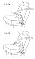
Fig. 1] Figs. 1a and 1b are perspective views of a seat equipped with an air belt apparatus according to an embodiment. - [
Fig. 2] Figs. 2a and 2b illustrate an anchor portion of an air belt. - [
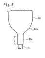
Fig. 3] Fig. 3 illustrates a relationship between a lap bag and a pipe. - [
Fig. 4] Fig. 4 illustrates a relationship between a lap bag and a pipe. - In an air belt apparatus according to the present invention, a pipe is inserted in a gas inlet to extend beyond an inner end of the gas inlet. Since the portion adjoining the inner end of the gas inlet has a large inflation diameter, the severity of gas discharged from the pipe is alleviated. Accordingly, this reduces the required tolerance level of a bag to high-temperature gas.
- In a case where the gas inlet has a cylindrical shape with a uniform diameter, the pipe extends beyond the inner end of the cylindrical portion.
- In a case where the gas inlet has a tapered shape whose diameter becomes smaller from its entrance end toward its inner end, the pipe extends beyond the inner end of a narrow portion of the tapered gas inlet, which is where the gas inlet is at its smallest diameter.
- Embodiments according to the present invention will be described below with reference to the drawings.
-
Figs. 1a and 1b are perspective views of a seat equipped with an occupant restraining apparatus according to an embodiment.Fig. 1b shows a state where an air belt is inflated.Fig. 2a is a front view of an anchor portion.Fig. 2b is an enlarged view of a portion shown inFig. 2a .Fig. 3 illustrates a relationship between a bag and a pipe. - A
seat 1 of an automobile includes aseat frame 2, aseat cushion 3 disposed on theseat frame 2, aseat back 4 extending upward in a reclinable fashion from a rear portion of theseat cushion 3, and a headrest 5 attached to an upper portion of theseat back 4. One side surface of theseat frame 2, that is, the side surface proximate to the center of the vehicle cabin, is provided with a buckle device (not shown). Atongue 11 of anair belt 10, which is included in the occupant restraining apparatus and is extendable along the front side of the body of an occupant seated in theseat 1, is detachably connected to this buckle device. The other side surface of theseat frame 2, that is, the side surface proximate to a side surface (such as a door) of the vehicle cabin, is provided with aninflator 12 and alap anchor 13. - The
air belt 10 has awebbing 14 hooked through thetongue 11 and alap bag 15 connected to one end of thewebbing 14. The other end of thewebbing 14 is hooked through a shoulder anchor (not shown) provided on a B pillar and is retractably connected to a seatbelt retractor (not shown). - The
lap bag 15 includes abag body 16 and atubular cover 17 that covers thebag body 16. Normally, thebag body 16 is folded in a flat and elongated shape. When thebag body 16 is in a non-inflated state, thecover 17 has a size that fits around the outer periphery of the foldedbag body 16, but when thebag body 16 is inflated, thecover 17 expands in the circumferential direction thereof to permit the inflation of thebag body 16. - One end of the
cover 17 is connected to thewebbing 14 by, for example, stitching. The other end of thecover 17 extends through an opening 13a provided in thelap anchor 13 so as to be connected to thelap anchor 13. - In this embodiment, the
cover 17 is formed of a knit fabric that is expandable in the circumferential direction but is substantially non-expandable in the longitudinal direction. Therefore, when thebag body 16 is inflated, the meshes of thecover 17 expand in the circumferential direction with the stretching of thecover 17 in the circumferential direction. As a result, thecover 17 becomes shorter in the longitudinal direction. This causes thewebbing 14 to become tighter, whereby thewebbing 14 becomes in close contact with the occupant's body. - The
inflator 12 is connected to agas inlet 16a of thebag body 16 via apipe 18. Thegas inlet 16a is cylindrical and has length A from an entrance end thereof. An inner end of the gas inlet 16a adjoins a large-diameter portion 16b that has a diameter larger than that of thegas inlet 16a. Thepipe 18 is inserted into thecylindrical gas inlet 16a so as to extend to the large-diameter portion 16b that adjoins the inner end of thecylindrical gas inlet 16a. In other words, the tip end of thepipe 18 is disposed in the large-diameter portion 16b. - After the
pipe 18 is inserted into thegas inlet 16a, thepipe 18 and thegas inlet 16a are securely coupled to each other by tightening thegas inlet 16a with alashing member 19 such as a crimp band. - An end of the
cover 17 is connected to thelap anchor 13. Thelap anchor 13 is fixed to abase plate 20 with fixing means such as abolt 21. - The
inflator 12 is attached to thebase plate 20 by means of ahook portion 22 provided on thebase plate 20. Thelap anchor 13 is provided with ahook portion 24 which supports thepipe 18. An upper end of thepipe 18 is connected to thebag body 16, and a lower end thereof is engaged with agas outlet 12a of theinflator 12. - The
base plate 20 is fixed to theseat frame 2 with fixing means such asbolts 25. - Operation of the air belt apparatus will be described below.
- When an automobile collision is detected, the
inflator 12 is activated to discharge gas. The gas from the inflator 12 flows into thebag body 16 through thepipe 18 so as to inflate thelap bag 15. As a result, the waist portion of an occupant is restrained. In the event of a collision, theinflated lap bag 15 intervenes a sidewall of the vehicle cabin (such as a door) and the occupant to ensure that the waist portion of the occupant is prevented from moving towards the sidewall of the vehicle cabin. Thelap bag 15 can also serve as a buffer in a case where the sidewall of the vehicle cabin protrudes inward toward the occupant. Furthermore, when thelap bag 15 is shortened in length as a result of inflation, pre-tension is generated on the lap portion, thereby restraining the occupant. - In this embodiment, the
pipe 18 extends beyond the inner end of thegas inlet 16a. This alleviates the severity of gas discharged from thepipe 18 directly hitting the inner surface of thebag body 16. In other words, if the tip end of thepipe 18 is positioned within thegas inlet 16a, the high-temperature gas just released from thepipe 18 will directly hit the inner periphery surface of thegas inlet 16a. In particular, if thegas inlet 16a is bent or twisted, the gas will be directly blown against the inner surface of thegas inlet 16a. In contrast, in the present embodiment, the tip end of thepipe 18 extends to the large-diameter portion 16b adjoining the inner end of thegas inlet 16a so that thegas inlet 16a is prevented from becoming bent or twisted. In addition, due to a sufficient distance between the tip end of thepipe 18 and the inner surface of thebag body 16, heat load applied to thebag body 16 is reduced. Accordingly, the required tolerance level of thebag body 16 to gas discharged by the inflator is reduced. - Although the
gas inlet 16a of thebag body 16 inFig. 3 has a cylindrical shape when inflated, the gas inlet may alternatively be tapered such that the diameter thereof becomes smaller toward the inner end, as shown by agas inlet 16c of a bag body 16' inFig. 4 . In this embodiment, the taperedgas inlet 16c has length B from an entrance end thereof. Thepipe 18 inserted in thegas inlet 16c extends beyond an inner end of a narrow portion 16d, which is where thegas inlet 16c is at its smallest diameter. In other words, the tip end of thepipe 18 extends beyond the inner end of the narrow portion 16d so as to be positioned in a large-diameter portion 16f having a diameter larger than that of the narrow portion 16d. With this bag body 16', a sufficient distance is maintained between the tip end of thepipe 18 and the inner surface of the bag body 16', whereby the required tolerance level of the bag body 16' to gas discharged by the inflator is reduced. - Although the
entire gas inlet 16c is tapered inFig. 4 , it may partially be cylindrical. - The cross-sectional area of the
inflated bag body 16 or 16' where the tip end of thepipe 18 is positioned is more than or equal to 1.5 times that of the opening of the tip end of thepipe 18. For example, 1.5 to 6 times is preferable. - The above embodiments are examples of the present invention, and therefore, the present invention is not limited to the above embodiments.
This application is based on Japanese Patent Application (No.2005-330419
Claims (7)
- An air belt apparatus, wherein gas from an inflator is supplied to a bag via a pipe,
wherein the bag includes a gas inlet through which the pipe extends, and
wherein the pipe extends beyond an inner end of the gas inlet. - The air belt apparatus according to Claim 1, wherein the gas inlet has a cylindrical shape with a uniform diameter.
- The air belt apparatus according to Claim 1, wherein the gas inlet has a tapered shape whose diameter becomes smaller toward the inner end.
- The air belt apparatus according to Claim 2, wherein the bag includes a large-diameter portion adjoining the inner end of the gas inlet and having a diameter larger than that of the gas inlet, and wherein a tip end of the pipe is positioned in the large-diameter portion.
- The air belt apparatus according to Claim 3, wherein the bag includes a narrow portion corresponding to where the diameter of the gas inlet is the smallest, and a large-diameter portion having a diameter larger than that of the narrow portion, and wherein a tip end of the pipe is positioned in the large-diameter portion.
- The air belt apparatus according to Claim 1, wherein the gas inlet is coupled to the pipe by tightening the gas inlet with a lashing member.
- The air belt apparatus according to Claim 1, wherein a cross-sectional area of an inflated bag body where a tip end of the pipe is positioned is 1.5 to 6 times that of an opening of the tip end of the pipe.
Applications Claiming Priority (2)
| Application Number | Priority Date | Filing Date | Title |
|---|---|---|---|
| JP2005330419A JP4923531B2 (en) | 2005-11-15 | 2005-11-15 | Air belt device |
| PCT/JP2006/322263 WO2007058098A1 (en) | 2005-11-15 | 2006-11-08 | Air belt device |
Publications (3)
| Publication Number | Publication Date |
|---|---|
| EP1950102A1 true EP1950102A1 (en) | 2008-07-30 |
| EP1950102A4 EP1950102A4 (en) | 2009-03-11 |
| EP1950102B1 EP1950102B1 (en) | 2013-01-09 |
Family
ID=38048485
Family Applications (1)
| Application Number | Title | Priority Date | Filing Date |
|---|---|---|---|
| EP06823167A Ceased EP1950102B1 (en) | 2005-11-15 | 2006-11-08 | Air belt device |
Country Status (5)
| Country | Link |
|---|---|
| US (1) | US7866690B2 (en) |
| EP (1) | EP1950102B1 (en) |
| JP (1) | JP4923531B2 (en) |
| CN (1) | CN101213114A (en) |
| WO (1) | WO2007058098A1 (en) |
Families Citing this family (7)
| Publication number | Priority date | Publication date | Assignee | Title |
|---|---|---|---|---|
| US7862081B2 (en) * | 2008-10-09 | 2011-01-04 | Gm Global Technology Operations, Inc. | Motor vehicle safety restraint system |
| US7905514B2 (en) * | 2008-11-14 | 2011-03-15 | GM Global Technology Operations LLC | Motor vehicle safety restraint system |
| US8651519B2 (en) * | 2012-04-09 | 2014-02-18 | Autoliv Asp, Inc. | Seatbelt anchor airbag |
| JP5979111B2 (en) * | 2013-09-30 | 2016-08-24 | 豊田合成株式会社 | Crew protection device |
| DE102014200252A1 (en) * | 2014-01-09 | 2014-04-10 | Takata AG | Airbag arrangement for vehicle, has air bag and filling unit for filling air bag with gas, where filling unit is arranged in opening of air bag, and filling unit is elastically held in opening through adhesive arranged in area of opening |
| JP6680159B2 (en) * | 2016-09-16 | 2020-04-15 | トヨタ紡織株式会社 | Vehicle seat |
| JP7635734B2 (en) * | 2022-02-16 | 2025-02-26 | 豊田合成株式会社 | Occupant protection devices |
Family Cites Families (26)
| Publication number | Priority date | Publication date | Assignee | Title |
|---|---|---|---|---|
| US3801156A (en) * | 1971-11-15 | 1974-04-02 | H Granig | Safety-belt |
| US5062662A (en) * | 1990-05-16 | 1991-11-05 | Cameron Robert W | Vehicle seatbelt having an integral airbag |
| US5465999A (en) * | 1994-06-30 | 1995-11-14 | Takata Corporation | Inflatable seat belt having defined shape |
| US5466003A (en) * | 1994-06-30 | 1995-11-14 | Takata Corporation | Inflatable seat belt having bag filter |
| US6168195B1 (en) * | 1997-07-15 | 2001-01-02 | Honda Giken Kogyo Kabushiki Kaisha | Occupant protecting device |
| JP3433654B2 (en) * | 1997-09-02 | 2003-08-04 | タカタ株式会社 | Air belt device |
| JP3465547B2 (en) * | 1997-09-02 | 2003-11-10 | タカタ株式会社 | Air belt device |
| JPH11165605A (en) | 1997-12-05 | 1999-06-22 | Honda Motor Co Ltd | Air belt device |
| US6109647A (en) * | 1997-12-15 | 2000-08-29 | Honda Giken Kogyo Kabushiki Kaisha | Seat-occupant restraining apparatus |
| DE19804365C2 (en) * | 1998-02-04 | 2000-06-08 | Hs Tech & Design | Three-point seat belt |
| JP2000085510A (en) * | 1998-09-14 | 2000-03-28 | Takata Kk | Structure of connecting airbag and inflator |
| JP3809736B2 (en) * | 1998-12-24 | 2006-08-16 | タカタ株式会社 | Air belt device |
| JP3899723B2 (en) * | 1999-03-10 | 2007-03-28 | タカタ株式会社 | Air belt device |
| JP4055356B2 (en) * | 1999-11-16 | 2008-03-05 | 住友電装株式会社 | connector |
| US6471243B1 (en) * | 2000-09-07 | 2002-10-29 | Trw Vehicle Safety Systems Inc. | Inflation mechanism for inflatable seat belt |
| JP4573285B2 (en) * | 2000-12-18 | 2010-11-04 | タカタ株式会社 | Inflatable seat belt device |
| JP3528818B2 (en) * | 2000-12-27 | 2004-05-24 | トヨタ自動車株式会社 | Airbag device |
| US6523873B1 (en) * | 2001-08-17 | 2003-02-25 | Alcoa Inc. | Taper and flare energy absorption system |
| JP3835257B2 (en) * | 2001-11-12 | 2006-10-18 | 豊田合成株式会社 | Head protection airbag device |
| EP1479570B1 (en) * | 2002-02-26 | 2006-06-14 | Dalphi Metal Espana, S.A. | Seat belt with built-in airbag for vehicles |
| JP3912195B2 (en) * | 2002-06-12 | 2007-05-09 | タカタ株式会社 | Crew protection device |
| GB0306986D0 (en) * | 2003-03-26 | 2003-04-30 | Autoliv Dev | Improvements in or relating to an air-bag arrangement |
| JP2005178612A (en) * | 2003-12-19 | 2005-07-07 | Takata Corp | Curtain airbag device |
| JP2006117219A (en) * | 2004-02-20 | 2006-05-11 | Takata Corp | Occupant crash protection device |
| JP2005239055A (en) * | 2004-02-27 | 2005-09-08 | Takata Corp | Occupant crash protection device |
| JP2005330419A (en) | 2004-05-21 | 2005-12-02 | Hiroaki Kanazawa | Production method of negative ion powder, adhesive, seal and synthetic resin material for molding |
-
2005
- 2005-11-15 JP JP2005330419A patent/JP4923531B2/en not_active Expired - Fee Related
-
2006
- 2006-11-08 WO PCT/JP2006/322263 patent/WO2007058098A1/en not_active Ceased
- 2006-11-08 CN CNA2006800239266A patent/CN101213114A/en active Pending
- 2006-11-08 US US11/992,413 patent/US7866690B2/en not_active Expired - Fee Related
- 2006-11-08 EP EP06823167A patent/EP1950102B1/en not_active Ceased
Also Published As
| Publication number | Publication date |
|---|---|
| EP1950102A4 (en) | 2009-03-11 |
| CN101213114A (en) | 2008-07-02 |
| EP1950102B1 (en) | 2013-01-09 |
| US20090108570A1 (en) | 2009-04-30 |
| JP2007137133A (en) | 2007-06-07 |
| US7866690B2 (en) | 2011-01-11 |
| WO2007058098A1 (en) | 2007-05-24 |
| JP4923531B2 (en) | 2012-04-25 |
Similar Documents
| Publication | Publication Date | Title |
|---|---|---|
| US10328889B2 (en) | Vehicle occupant protection device | |
| EP1568537B1 (en) | Occupant protection device | |
| US7883106B2 (en) | Inflatable seat belt including a thorax airbag | |
| JP5382199B2 (en) | Side airbag device for vehicle | |
| US8066303B2 (en) | Vehicle occupant restraint system | |
| EP2617606A1 (en) | Anchoring structure for vehicle rear-side airbag | |
| US20170136976A1 (en) | Vehicle occupant protection device | |
| US7905514B2 (en) | Motor vehicle safety restraint system | |
| US7322603B2 (en) | Seat belt system including an airbag | |
| EP1369314A2 (en) | Occupant protection apparatus | |
| US7862081B2 (en) | Motor vehicle safety restraint system | |
| JP7408507B2 (en) | Occupant protection device | |
| JP4174515B2 (en) | Air belt device for vehicle | |
| US10308205B2 (en) | Safety restraint system with an airbag having an inflatable pelvis restraint portion and related method | |
| US7871105B2 (en) | Air belt device | |
| US7207595B2 (en) | Side airbag apparatus | |
| CN112533798A (en) | Side airbag device | |
| EP1950102B1 (en) | Air belt device | |
| JP2007161205A (en) | Occupant restraining device | |
| EP4474226A1 (en) | Vehicular side airbag device | |
| JP2022110958A (en) | Vehicular side airbag device | |
| JP2007161203A (en) | Occupant restraining device | |
| JP5476191B2 (en) | Air belt device | |
| JP7408508B2 (en) | Occupant protection device | |
| EP4596332A1 (en) | Vehicular side airbag device |
Legal Events
| Date | Code | Title | Description |
|---|---|---|---|
| PUAI | Public reference made under article 153(3) epc to a published international application that has entered the european phase |
Free format text: ORIGINAL CODE: 0009012 |
|
| 17P | Request for examination filed |
Effective date: 20080509 |
|
| AK | Designated contracting states |
Kind code of ref document: A1 Designated state(s): DE GB |
|
| DAX | Request for extension of the european patent (deleted) | ||
| RBV | Designated contracting states (corrected) |
Designated state(s): DE GB |
|
| A4 | Supplementary search report drawn up and despatched |
Effective date: 20090205 |
|
| 17Q | First examination report despatched |
Effective date: 20090720 |
|
| REG | Reference to a national code |
Ref country code: DE Ref legal event code: R079 Ref document number: 602006034169 Country of ref document: DE Free format text: PREVIOUS MAIN CLASS: B60R0021180000 Ipc: B60R0021260000 |
|
| GRAP | Despatch of communication of intention to grant a patent |
Free format text: ORIGINAL CODE: EPIDOSNIGR1 |
|
| RIC1 | Information provided on ipc code assigned before grant |
Ipc: B60R 21/26 20110101AFI20120530BHEP Ipc: B60R 21/18 20060101ALI20120530BHEP |
|
| GRAS | Grant fee paid |
Free format text: ORIGINAL CODE: EPIDOSNIGR3 |
|
| GRAA | (expected) grant |
Free format text: ORIGINAL CODE: 0009210 |
|
| AK | Designated contracting states |
Kind code of ref document: B1 Designated state(s): DE GB |
|
| REG | Reference to a national code |
Ref country code: GB Ref legal event code: FG4D |
|
| REG | Reference to a national code |
Ref country code: DE Ref legal event code: R096 Ref document number: 602006034169 Country of ref document: DE Effective date: 20130307 |
|
| PLBE | No opposition filed within time limit |
Free format text: ORIGINAL CODE: 0009261 |
|
| STAA | Information on the status of an ep patent application or granted ep patent |
Free format text: STATUS: NO OPPOSITION FILED WITHIN TIME LIMIT |
|
| 26N | No opposition filed |
Effective date: 20131010 |
|
| PGFP | Annual fee paid to national office [announced via postgrant information from national office to epo] |
Ref country code: GB Payment date: 20131106 Year of fee payment: 8 |
|
| REG | Reference to a national code |
Ref country code: DE Ref legal event code: R097 Ref document number: 602006034169 Country of ref document: DE Effective date: 20131010 |
|
| GBPC | Gb: european patent ceased through non-payment of renewal fee |
Effective date: 20141108 |
|
| PG25 | Lapsed in a contracting state [announced via postgrant information from national office to epo] |
Ref country code: GB Free format text: LAPSE BECAUSE OF NON-PAYMENT OF DUE FEES Effective date: 20141108 |
|
| PGFP | Annual fee paid to national office [announced via postgrant information from national office to epo] |
Ref country code: DE Payment date: 20171121 Year of fee payment: 12 |
|
| REG | Reference to a national code |
Ref country code: DE Ref legal event code: R082 Ref document number: 602006034169 Country of ref document: DE Representative=s name: KRAUS & WEISERT PATENTANWAELTE PARTGMBB, DE Ref country code: DE Ref legal event code: R081 Ref document number: 602006034169 Country of ref document: DE Owner name: JOYSON SAFETY SYSTEMS JAPAN K.K., JP Free format text: FORMER OWNER: TAKATA CORPORATION, MINATO-KU, TOKYO, JP |
|
| REG | Reference to a national code |
Ref country code: DE Ref legal event code: R119 Ref document number: 602006034169 Country of ref document: DE |
|
| PG25 | Lapsed in a contracting state [announced via postgrant information from national office to epo] |
Ref country code: DE Free format text: LAPSE BECAUSE OF NON-PAYMENT OF DUE FEES Effective date: 20190601 |