EP1949974A1 - Sprayer Assembly - Google Patents
Sprayer Assembly Download PDFInfo
- Publication number
- EP1949974A1 EP1949974A1 EP07123794A EP07123794A EP1949974A1 EP 1949974 A1 EP1949974 A1 EP 1949974A1 EP 07123794 A EP07123794 A EP 07123794A EP 07123794 A EP07123794 A EP 07123794A EP 1949974 A1 EP1949974 A1 EP 1949974A1
- Authority
- EP
- European Patent Office
- Prior art keywords
- bracket
- frame
- sprayer assembly
- nozzle body
- set forth
- Prior art date
- Legal status (The legal status is an assumption and is not a legal conclusion. Google has not performed a legal analysis and makes no representation as to the accuracy of the status listed.)
- Withdrawn
Links
- 238000005266 casting Methods 0.000 claims description 18
- 230000000087 stabilizing effect Effects 0.000 claims description 2
- 239000002991 molded plastic Substances 0.000 abstract description 2
- 239000007921 spray Substances 0.000 description 7
- 239000000126 substance Substances 0.000 description 5
- 239000000463 material Substances 0.000 description 3
- 238000010899 nucleation Methods 0.000 description 3
- 239000007788 liquid Substances 0.000 description 2
- 238000004519 manufacturing process Methods 0.000 description 2
- 239000002689 soil Substances 0.000 description 2
- 238000000429 assembly Methods 0.000 description 1
- 230000000712 assembly Effects 0.000 description 1
- 238000000151 deposition Methods 0.000 description 1
- 239000003337 fertilizer Substances 0.000 description 1
- 230000014759 maintenance of location Effects 0.000 description 1
- 239000002184 metal Substances 0.000 description 1
- 238000012986 modification Methods 0.000 description 1
- 230000004048 modification Effects 0.000 description 1
- 239000000575 pesticide Substances 0.000 description 1
- 239000004033 plastic Substances 0.000 description 1
Images


Classifications
-
- A—HUMAN NECESSITIES
- A01—AGRICULTURE; FORESTRY; ANIMAL HUSBANDRY; HUNTING; TRAPPING; FISHING
- A01M—CATCHING, TRAPPING OR SCARING OF ANIMALS; APPARATUS FOR THE DESTRUCTION OF NOXIOUS ANIMALS OR NOXIOUS PLANTS
- A01M7/00—Special adaptations or arrangements of liquid-spraying apparatus for purposes covered by this subclass
- A01M7/005—Special arrangements or adaptations of the spraying or distributing parts, e.g. adaptations or mounting of the spray booms, mounting of the nozzles, protection shields
- A01M7/006—Mounting of the nozzles
-
- A—HUMAN NECESSITIES
- A01—AGRICULTURE; FORESTRY; ANIMAL HUSBANDRY; HUNTING; TRAPPING; FISHING
- A01C—PLANTING; SOWING; FERTILISING
- A01C23/00—Distributing devices specially adapted for liquid manure or other fertilising liquid, including ammonia, e.g. transport tanks or sprinkling wagons
- A01C23/02—Special arrangements for delivering the liquid directly into the soil
- A01C23/023—Special arrangements for delivering the liquid directly into the soil for liquid or gas fertilisers
- A01C23/025—Continuous injection tools
-
- A—HUMAN NECESSITIES
- A01—AGRICULTURE; FORESTRY; ANIMAL HUSBANDRY; HUNTING; TRAPPING; FISHING
- A01C—PLANTING; SOWING; FERTILISING
- A01C7/00—Sowing
- A01C7/06—Seeders combined with fertilising apparatus
-
- B—PERFORMING OPERATIONS; TRANSPORTING
- B05—SPRAYING OR ATOMISING IN GENERAL; APPLYING FLUENT MATERIALS TO SURFACES, IN GENERAL
- B05B—SPRAYING APPARATUS; ATOMISING APPARATUS; NOZZLES
- B05B15/00—Details of spraying plant or spraying apparatus not otherwise provided for; Accessories
- B05B15/60—Arrangements for mounting, supporting or holding spraying apparatus
- B05B15/62—Arrangements for supporting spraying apparatus, e.g. suction cups
Definitions
- the present invention relates generally to a sprayer assembly for mounting on the frame of an agricultural implement.
- a typical application arrangement includes a spray nozzle for applying liquid pesticide or other chemical.
- the nozzle is supported in a bracket that is connected to the frame of a planter row unit by bolts at a location immediately rearwardly of the furrow opening disk.
- Space is extremely limited on the row unit frame, and the mounting of the entire spray assembly can be difficult and time consuming.
- the nozzle operates in a relatively harsh environment, and high impact forces can damage the spray assembly. Repair and replacement of the nozzle are inconvenient because of the limited space and number of mounting components.
- one object of the invention is to provide a sprayer assembly which has a minimal number of parts and which is easy to mount and to replace on a planter row unit.
- a sprayer assembly as described above comprises a bracket with a slotted wall, a nozzle body having projecting tab structure for receipt in the slotted wall and a single connector for securing the bracket to the frame.
- the slotted wall comprises parallel spaced slots receiving the tab structure, wherein the nozzle body is slidable along the slots to a mounted position.
- the slots include an offset, wherein the tab structure is slidably moveable in the slot relative to the offset and securing the nozzle body in the mounted position when the tab structure slides past the offset.
- the sprayer assembly may further comprise a nozzle cap attachable to the nozzle body, wherein the nozzle cap when attached projects past a plane of the slotted wall and limiting sliding movement of the nozzle body along the slots away from the mounted position.
- the bracket may include a leg structure projecting from the slotted wall into contact with the frame for stabilizing the bracket and the nozzle body.
- the single connector comprises a single bolt tightened against the bracket, wherein the single bolt and leg structure providing substantially all the support of the bracket and the nozzle body relative to the frame.
- the frame may include a frame casting bolted to the implement, wherein the single bolt also supports the frame casting.
- the frame may comprise a planter row unit frame.
- the frame casting may define a downwardly opening cavity, wherein the bracket is contained within the cavity.
- the bracket includes first and second bracket portions extending laterally from opposite ends of the slotted wall, wherein the first bracket portion is secured to the frame by the single connector and the second bracket portion is resilient and is biased against the frame.
- a sprayer assembly for mounting on the frame of an agricultural implement, comprises a bracket with a slotted wall lying generally in a plane and a nozzle body having projecting tab structure for receipt in the slotted wall, wherein the tab structure is movable in the slotted wall to an assembled position on the bracket.
- the sprayer assembly may comprise a nozzle cap attachable to and removable from the nozzle body, the nozzle cap when attached to the nozzle body limiting movement of the nozzle body away from the assembled position.
- the bracket includes an upper wall connected by a single bolt to the frame and lower leg structure biased against the frame to stabilize the bracket and nozzle body.
- the slotted wall may comprise parallel slots receiving the tab structure, wherein the slots include an offset, the tab structure slidable in the slot relative the offset and securing the nozzle body in the mounted position when the tab structure slides past the offset.
- the nozzle cap when attached projects past the plane of the slotted wall and limits movement of the nozzle body along the slots away from the assembled position.
- the slotted wall includes a lower edge, wherein the nozzle cap is positioned adjacent the lower edge when attached and contacts the lower edge as the nozzle body is urged upwardly to direct impact loading away from the nozzle body to the nozzle cap and the bracket.
- the sprayer assembly comprises a single bolt tightened against the bracket, the single bolt and leg structure providing substantially all the support of the bracket and the nozzle body relative to the frame.
- the frame includes a frame casting bolted to the implement, wherein the single bolt also supports the frame casting.
- the frame may comprise a planter row unit frame.
- the frame casting defines a downwardly opening cavity and the bracket is contained within the cavity.
- the bracket includes first and second bracket portions extending laterally from opposite ends of the slotted wall, wherein the first bracket portion is secured to the frame by a single connector and the second bracket portion is resilient and is biased against the frame.
- the bracket has extensions that conform to and abut the row unit frame casting to provide additional strength while facilitating easy access to the mounting bolt.
- a molded plastic nozzle body includes mounting tabs received by the bracket slots. The tabs snap fit into the bracket slots, and the nozzle body is guided into position by the slots.
- a nozzle cap threaded onto the body adjacent the bracket constrains the body against upward movement to provide a secure nozzle body connection and eliminate or minimize impact damage to the body. The easily replaceable cap contacts the bracket and protects the more costly nozzle body from damage.
- the assembly is easily installed in the limited space area of the row unit frame and can be conveniently accessed for servicing or changing a nozzle. The entire assembly has few total parts, is extremely compact and is relatively inexpensive to manufacture and install.
- the present invention relates generally to spray nozzle assemblies for agricultural implements and, more specifically, to a nozzle assembly that is particularly useful for attachment on the frame of a seeding device such as a planter row unit.
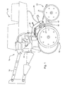
- the seeding device 10 is a planter including a row unit 12 having a forward end 14 connected by a four-bar linkage 16 to a toolbar (not shown).
- Conventional furrow opening structure 18 with depth gauging is connected to an opener frame 20 and opens a furrow in the ground and deposits material such as seed and fertilizer in the furrow.
- Trailing press wheel structure 22 supported from the frame 20 at a pivot location 24 firms the soil over the deposited material.
- the opener frame 20 includes a frame casting 30 connected by bolts 32 and 34 ( Figure 2 ) to an underside of the frame 20 immediately rearwardly of the opening structure 18.
- the casting 30 includes an upper apertured portion 36 receiving the bolts 32 and 34 and a chemical supply line 38.
- the casting 30 extends rearwardly and downwardly from the apertured portion 36 to a downwardly and forwardly extending mounting portion 40 that terminates at a lowermost end in an apertured mounting member 42 for receiving one end of a firming wheel down pressure spring 44.
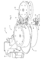
- the casting 30 defines a downwardly and forwardly opening cavity indicated generally at 48. As best seen in Figure 2 , access to the cavity area is relatively limited.
- a sprayer assembly comprising a nozzle and bracket assembly 50 is secured generally within the cavity 48 by a single connector in form of the bolt 34.
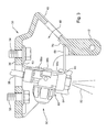
- the supply line 38 feeds a chemical solution to the top of the assembly 50, and a chemical spray 52 ( Figure 3 ) is emitted from the bottom of the assembly onto the area of the furrow near the rear of the opener assembly 18.
- the assembly 50 includes a formed sheet metal bracket 60 having a generally horizontal top portion 62 with a slot 64 opening all the way through the rearmost edge of the portion ( Figures 4 and 5 ).
- a forward and generally planar slotted wall 66 with spaced upright slots 66a extends downwardly and slopes slightly forwardly from the top portion 62.
- a leg structure comprising two identical legs 68 are bent rearwardly from the bottom and extend generally horizontally to upturned ends 70.
- the bolt 34 secures the top portion 62 against the bottom surface of the portion 36.
- the ends 70 of the legs 68 conform to and are resiliently supported against the inside wall of the mounting portion 40.
- bracket 60 is secured firmly in place in the cavity 48 using only the single bolt 34 and contact between the ends 70 and the casting 30. Therefore, although the space in the area of the cavity 48 is limited, attachment and removal of the assembly 50 is facilitated.
- the assembly 50 also includes a nozzle body 80 having an upper inlet 82 connected to the supply line 38 and a nozzle cap 84 releasably mounted on the lower end of the body 80 and defining the spray pattern for the spray 52.
- the body 80 as shown is molded from plastic material and includes rearwardly projecting spaced upper and lower mounting tabs 86a and 86b received by the slots 66a in the wall 66.
- the tabs 86a and 86b extend through the slots 66a and embrace opposite edges of the slots for firm support by the slotted wall 66.
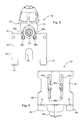
- the ends of the tabs 86 have laterally directed protrusions ( Figure 7 ) to help secure the body 80 in the slots 66a.
- the slots 66a have centrally located offsets 66b that contact the upper tabs 86a as the body 80 is slid downwardly into the final assembled position on the bracket 60.
- the offsets 66b help resist upward movement of the body 80 in the slots 66a and maintain the body 80 in the desired position.
- the nozzle cap 84 which is connected to the lower end of the body 80 after the body is slid into position on the bracket 60 by a conventional attachment structure such as a bayonet mount, overlaps the plane of the slotted wall 66 and contacts the wall 66 if for any reason the body 80 is pushed upwardly.
- the wall 66 includes a downwardly opening aperture or slot 66c between the bend locations of the legs 68, and the upper planar surface of the cap 84 (see 84c of Figure 4 ) will contact the lower edge of the slot 66c if the body 80 is forced upwardly a fraction of a millimeter.
- This interference between the nozzle cap 84 and the bracket 60 provides added nozzle body retention and makes the assembly 50 more robust and resistant to damage.
- the attached nozzle cap 84 closely adjacent the lower edge contacts the edge of 66c at 84c as the nozzle body 80 is urged upwardly and thereby transfers impact loading from the nozzle cap to the frame through the bracket 60 to prevent nozzle body damage.
- the relatively inexpensive cap 84 can be easily replaced if damaged and prevents damage to the more expensive nozzle body 80.
- the tabs 86a and 86b of the nozzle body 80 are inserted into the slots and slid downwardly into a final mounting position past the slot offsets 66b ( Figure 7 ), and the nozzle cap 84 is attached.
- the casting 30 is secured to the opener frame 20 with the bolts 32 and 34.
- the bracket 60 is attached by sliding the slot 64 under the head of the bolt 34 and positioning the leg ends 70 against the mounting portion 40 ( Figure 2 ).
- the bolt 34 is then fully tightened to secure the assembly 50 in the casting 30. Assembly and disassembly of the sprayer assembly on the opener frame is therefore very simple and convenient. The above-described assembly facilitates manufacture and servicing and requires only several parts.
Landscapes
- Life Sciences & Earth Sciences (AREA)
- Soil Sciences (AREA)
- Environmental Sciences (AREA)
- Engineering & Computer Science (AREA)
- Pest Control & Pesticides (AREA)
- Insects & Arthropods (AREA)
- Water Supply & Treatment (AREA)
- Wood Science & Technology (AREA)
- Zoology (AREA)
- Catching Or Destruction (AREA)
- Cultivation Receptacles Or Flower-Pots, Or Pots For Seedlings (AREA)
- Fertilizing (AREA)
- Nozzles (AREA)
Abstract
Description
- The present invention relates generally to a sprayer assembly for mounting on the frame of an agricultural implement.
- Liquid chemicals are often applied in bands or in furrow over an open furrow during planting operations. A typical application arrangement includes a spray nozzle for applying liquid pesticide or other chemical. The nozzle is supported in a bracket that is connected to the frame of a planter row unit by bolts at a location immediately rearwardly of the furrow opening disk. Space is extremely limited on the row unit frame, and the mounting of the entire spray assembly can be difficult and time consuming. The nozzle operates in a relatively harsh environment, and high impact forces can damage the spray assembly. Repair and replacement of the nozzle are inconvenient because of the limited space and number of mounting components.
- According to the problems described above one object of the invention is to provide a sprayer assembly which has a minimal number of parts and which is easy to mount and to replace on a planter row unit.
- The object as described above will be solved by the teaching of claim 1. Further advantageous embodiments of the invention are defined in the accompanying claims.
- According to the invention a sprayer assembly as described above comprises a bracket with a slotted wall, a nozzle body having projecting tab structure for receipt in the slotted wall and a single connector for securing the bracket to the frame.
- In a preferred embodiment the slotted wall comprises parallel spaced slots receiving the tab structure, wherein the nozzle body is slidable along the slots to a mounted position. The slots include an offset, wherein the tab structure is slidably moveable in the slot relative to the offset and securing the nozzle body in the mounted position when the tab structure slides past the offset.
- The sprayer assembly may further comprise a nozzle cap attachable to the nozzle body, wherein the nozzle cap when attached projects past a plane of the slotted wall and limiting sliding movement of the nozzle body along the slots away from the mounted position.
- The bracket may include a leg structure projecting from the slotted wall into contact with the frame for stabilizing the bracket and the nozzle body.
- In another preferred embodiment the single connector comprises a single bolt tightened against the bracket, wherein the single bolt and leg structure providing substantially all the support of the bracket and the nozzle body relative to the frame.
- Furthermore the frame may include a frame casting bolted to the implement, wherein the single bolt also supports the frame casting. The frame may comprise a planter row unit frame. The frame casting may define a downwardly opening cavity, wherein the bracket is contained within the cavity.
- In another preferred embodiment the bracket includes first and second bracket portions extending laterally from opposite ends of the slotted wall, wherein the first bracket portion is secured to the frame by the single connector and the second bracket portion is resilient and is biased against the frame.
- In another preferred embodiment a sprayer assembly for mounting on the frame of an agricultural implement, comprises a bracket with a slotted wall lying generally in a plane and a nozzle body having projecting tab structure for receipt in the slotted wall, wherein the tab structure is movable in the slotted wall to an assembled position on the bracket. The sprayer assembly may comprise a nozzle cap attachable to and removable from the nozzle body, the nozzle cap when attached to the nozzle body limiting movement of the nozzle body away from the assembled position.
- The bracket includes an upper wall connected by a single bolt to the frame and lower leg structure biased against the frame to stabilize the bracket and nozzle body.
The slotted wall may comprise parallel slots receiving the tab structure, wherein the slots include an offset, the tab structure slidable in the slot relative the offset and securing the nozzle body in the mounted position when the tab structure slides past the offset. - The nozzle cap when attached projects past the plane of the slotted wall and limits movement of the nozzle body along the slots away from the assembled position.
- The slotted wall includes a lower edge, wherein the nozzle cap is positioned adjacent the lower edge when attached and contacts the lower edge as the nozzle body is urged upwardly to direct impact loading away from the nozzle body to the nozzle cap and the bracket.
- The sprayer assembly comprises a single bolt tightened against the bracket, the single bolt and leg structure providing substantially all the support of the bracket and the nozzle body relative to the frame.
- The frame includes a frame casting bolted to the implement, wherein the single bolt also supports the frame casting. The frame may comprise a planter row unit frame.
- The frame casting defines a downwardly opening cavity and the bracket is contained within the cavity. The bracket includes first and second bracket portions extending laterally from opposite ends of the slotted wall, wherein the first bracket portion is secured to the frame by a single connector and the second bracket portion is resilient and is biased against the frame.
- The sprayer assembly having a minimal number of parts and particularly useful for mounting on a planter row unit includes a slotted bracket connected by a single bolt to the unit frame. The bracket has extensions that conform to and abut the row unit frame casting to provide additional strength while facilitating easy access to the mounting bolt. A molded plastic nozzle body includes mounting tabs received by the bracket slots. The tabs snap fit into the bracket slots, and the nozzle body is guided into position by the slots. A nozzle cap threaded onto the body adjacent the bracket constrains the body against upward movement to provide a secure nozzle body connection and eliminate or minimize impact damage to the body. The easily replaceable cap contacts the bracket and protects the more costly nozzle body from damage. The assembly is easily installed in the limited space area of the row unit frame and can be conveniently accessed for servicing or changing a nozzle. The entire assembly has few total parts, is extremely compact and is relatively inexpensive to manufacture and install.
- The present invention relates generally to spray nozzle assemblies for agricultural implements and, more specifically, to a nozzle assembly that is particularly useful for attachment on the frame of a seeding device such as a planter row unit.
- These and other objects, features and advantages of the present invention will become apparent from the description below taken with the drawings.
-
Figure 1 is a side view of a planter row unit with a nozzle assembly attached. -
Figure 2 is a bottom perspective view of the aft portion of the planter row unit ofFigure 1 showing the nozzle support area with the nozzle assembly removed. -
Figure 3 is a side view, partially in section, of a frame casting from the support area with the nozzle assembly attached. -
Figure 4 is a perspective view of the nozzle assembly ofFigure 3 . -
Figure 5 is a top view of the nozzle assembly. -
Figure 6 is a rear view of the nozzle assembly showing the nozzle body in the mounted position on the nozzle bracket. -
Figure 7 is a perspective view of the nozzle assembly illustrating the attachment features. - Referring to
Figure 1 therein is shown a portion of aseeding device 10 adapted for movement over the soil for depositing seed in a furrow and closing the furrow over the seed. As shown, theseeding device 10 is a planter including arow unit 12 having aforward end 14 connected by a four-bar linkage 16 to a toolbar (not shown). Conventionalfurrow opening structure 18 with depth gauging is connected to anopener frame 20 and opens a furrow in the ground and deposits material such as seed and fertilizer in the furrow. Trailingpress wheel structure 22 supported from theframe 20 at apivot location 24 firms the soil over the deposited material. - The
opener frame 20 includes aframe casting 30 connected bybolts 32 and 34 (Figure 2 ) to an underside of theframe 20 immediately rearwardly of theopening structure 18. Thecasting 30 includes an upper aperturedportion 36 receiving thebolts chemical supply line 38. Thecasting 30 extends rearwardly and downwardly from theapertured portion 36 to a downwardly and forwardly extendingmounting portion 40 that terminates at a lowermost end in an aperturedmounting member 42 for receiving one end of a firming wheel downpressure spring 44. Thecasting 30 defines a downwardly and forwardly opening cavity indicated generally at 48. As best seen inFigure 2 , access to the cavity area is relatively limited. - A sprayer assembly comprising a nozzle and
bracket assembly 50 is secured generally within thecavity 48 by a single connector in form of thebolt 34. Thesupply line 38 feeds a chemical solution to the top of theassembly 50, and a chemical spray 52 (Figure 3 ) is emitted from the bottom of the assembly onto the area of the furrow near the rear of theopener assembly 18. - The
assembly 50 includes a formedsheet metal bracket 60 having a generallyhorizontal top portion 62 with aslot 64 opening all the way through the rearmost edge of the portion (Figures 4 and5 ). A forward and generally planarslotted wall 66 with spacedupright slots 66a extends downwardly and slopes slightly forwardly from thetop portion 62. A leg structure comprising twoidentical legs 68 are bent rearwardly from the bottom and extend generally horizontally toupturned ends 70. Thebolt 34 secures thetop portion 62 against the bottom surface of theportion 36. Theends 70 of thelegs 68 conform to and are resiliently supported against the inside wall of themounting portion 40. As can be best appreciated fromFigure 3 , thebracket 60 is secured firmly in place in thecavity 48 using only thesingle bolt 34 and contact between theends 70 and thecasting 30. Therefore, although the space in the area of thecavity 48 is limited, attachment and removal of theassembly 50 is facilitated. - The
assembly 50 also includes anozzle body 80 having anupper inlet 82 connected to thesupply line 38 and anozzle cap 84 releasably mounted on the lower end of thebody 80 and defining the spray pattern for thespray 52. Thebody 80 as shown is molded from plastic material and includes rearwardly projecting spaced upper and lower mountingtabs slots 66a in thewall 66. Thetabs slots 66a and embrace opposite edges of the slots for firm support by the slottedwall 66. The ends of the tabs 86 have laterally directed protrusions (Figure 7 ) to help secure thebody 80 in theslots 66a. Also, theslots 66a have centrally locatedoffsets 66b that contact theupper tabs 86a as thebody 80 is slid downwardly into the final assembled position on thebracket 60. Theoffsets 66b help resist upward movement of thebody 80 in theslots 66a and maintain thebody 80 in the desired position. - For added assembly integrity and body impact protection, the
nozzle cap 84, which is connected to the lower end of thebody 80 after the body is slid into position on thebracket 60 by a conventional attachment structure such as a bayonet mount, overlaps the plane of the slottedwall 66 and contacts thewall 66 if for any reason thebody 80 is pushed upwardly. As shown inFigure 4 , thewall 66 includes a downwardly opening aperture orslot 66c between the bend locations of thelegs 68, and the upper planar surface of the cap 84 (see 84c ofFigure 4 ) will contact the lower edge of theslot 66c if thebody 80 is forced upwardly a fraction of a millimeter. This interference between thenozzle cap 84 and thebracket 60 provides added nozzle body retention and makes theassembly 50 more robust and resistant to damage. The attachednozzle cap 84 closely adjacent the lower edge contacts the edge of 66c at 84c as thenozzle body 80 is urged upwardly and thereby transfers impact loading from the nozzle cap to the frame through thebracket 60 to prevent nozzle body damage. The relativelyinexpensive cap 84 can be easily replaced if damaged and prevents damage to the moreexpensive nozzle body 80. - During assembly, the
tabs nozzle body 80 are inserted into the slots and slid downwardly into a final mounting position past the slot offsets 66b (Figure 7 ), and thenozzle cap 84 is attached. The casting 30 is secured to theopener frame 20 with thebolts bolt 34 is completely tightened, thebracket 60 is attached by sliding theslot 64 under the head of thebolt 34 and positioning the leg ends 70 against the mounting portion 40 (Figure 2 ). Thebolt 34 is then fully tightened to secure theassembly 50 in the casting 30. Assembly and disassembly of the sprayer assembly on the opener frame is therefore very simple and convenient. The above-described assembly facilitates manufacture and servicing and requires only several parts. - Having described the preferred embodiment, it will become apparent that various modifications can be made without departing from the scope of the invention as defined in the accompanying claims.
Claims (12)
- A sprayer assembly (50) for mounting on the frame (20) of an agricultural implement, characterized in comprising a bracket (60) with a slotted wall (66), a nozzle body (80) having projecting tab structure (86, 86a, 86b) for receipt in the slotted wall (66), and a single connector for securing the bracket (60) to the frame (20).
- The sprayer assembly (50) as set forth in claim 1 wherein the tab structure (86, 86a, 86b) is moveable in the slotted wall (66) to an assembled position on the bracket (60).
- The sprayer assembly (50) as set forth in claim 1 or 2 wherein the slotted wall (60) comprises parallel spaced slots (66a) receiving the tab structure (86, 86a, 86b), wherein the nozzle body (80) is moveable along the slots (66a) to a mounted position.
- The sprayer assembly (50) as set forth in claim 2 or 3 wherein the slots (66a) include an offset (66b), the tab structure (86, 86a, 86b) slidable in the slot (66a) relative the offset (66b) and securing the nozzle body (80) in the mounted position when the tab structure (86, 86a, 86b) slides past the offset (66b).
- The sprayer assembly (50) as set forth in one of the claims 2 to 4 further comprising a nozzle cap (84) attachable to the nozzle body (80) and/or removable from the nozzle body (80), the nozzle cap (84) when attached projects past a plane of the slotted wall (66) and limiting sliding movement of the nozzle body (80) along the slots (66a) away from the mounted position.
- The sprayer assembly (50) as set forth in one of the claims 1 to 5, wherein the bracket (60) includes leg structure (68) projecting from the slotted wall (66) into contact with the frame (20) for stabilizing the bracket (60) and nozzle body (80).
- The sprayer assembly (50) as set forth in claim 6 wherein the single connector comprises a single bolt (34) tightened against the bracket (60), the single bolt (34) and leg structure (68) providing substantially all the support of the bracket (60) and the nozzle body (80) relative to the frame (20).
- The sprayer assembly (50) as set forth in claim 7 wherein the bracket (60) includes an upper wall (62) connected by the single bolt (34) to the frame (20) and lower leg structure (68) biased against the frame (20) to stabilize the bracket (60) and nozzle body (80).
- The sprayer assembly (50) as set forth in claim 7 or 8 wherein the frame (20) includes a frame casting (30) bolted to the implement, and wherein the single bolt (34) also supports the frame casting (30).
- The sprayer assembly (50) as set forth in one of the claims 1 to 9 wherein the frame (20) comprises a planter row unit frame.
- The sprayer assembly (50) as set forth in claim 10 wherein the frame casting (30) defines a downwardly opening cavity (48), and the bracket (60) is contained within the cavity (48).
- The sprayer assembly (50) as set forth in claim 1 wherein the bracket (60) includes first and second bracket portions (62, 68) extending laterally from opposite ends of the slotted wall (66), wherein the first bracket portion (62) is secured to the frame (20) by the single connector and the second bracket portion (68) is resilient and is biased against the frame (20).
Applications Claiming Priority (1)
| Application Number | Priority Date | Filing Date | Title |
|---|---|---|---|
| US11/627,711 US20080179429A1 (en) | 2007-01-26 | 2007-01-26 | Spray nozzle mounting assembly |
Publications (1)
| Publication Number | Publication Date |
|---|---|
| EP1949974A1 true EP1949974A1 (en) | 2008-07-30 |
Family
ID=39338332
Family Applications (1)
| Application Number | Title | Priority Date | Filing Date |
|---|---|---|---|
| EP07123794A Withdrawn EP1949974A1 (en) | 2007-01-26 | 2007-12-20 | Sprayer Assembly |
Country Status (7)
| Country | Link |
|---|---|
| US (1) | US20080179429A1 (en) |
| EP (1) | EP1949974A1 (en) |
| AR (1) | AR065011A1 (en) |
| BR (1) | BRPI0800206A (en) |
| CA (1) | CA2618532A1 (en) |
| MX (1) | MX2008000555A (en) |
| RU (1) | RU2008102998A (en) |
Cited By (4)
| Publication number | Priority date | Publication date | Assignee | Title |
|---|---|---|---|---|
| DE102008052114A1 (en) * | 2008-10-20 | 2010-04-29 | Khs Ag | Spray nozzle arrangement, cleaning machine and spray nozzle |
| FR3018996A1 (en) * | 2014-04-01 | 2015-10-02 | Herve Bassan | DEVICE FOR IRONING YOUNG PLANTS, IN PARTICULAR VINE PLANTS |
| EP3469900A1 (en) * | 2017-10-11 | 2019-04-17 | Deere & Company | Sectional boom height control of individual section for sprayers and system thereof |
| CN110476581A (en) * | 2019-09-20 | 2019-11-22 | 陈碧珍 | A kind of flusher of the plantation convenient for the nutrient solution to spray head dismounting and change |
Families Citing this family (10)
| Publication number | Priority date | Publication date | Assignee | Title |
|---|---|---|---|---|
| DE102010034921A1 (en) * | 2010-08-20 | 2012-02-23 | Dürr Systems GmbH | Nozzle for application of a coating agent |
| US10144028B2 (en) | 2014-10-30 | 2018-12-04 | Cotton Tall Industries, LLC | Agricultural spray containment devices, systems and methods |
| US10420333B2 (en) | 2015-05-04 | 2019-09-24 | Deere & Company | Spray assembly for boom sprayer |
| RU2752979C2 (en) * | 2016-09-16 | 2021-08-11 | ПРЕСИЖН ПЛЭНТИНГ ЭлЭлСи | Agricultural beam for hanging working bodies (options) |
| CN107897161A (en) * | 2017-12-15 | 2018-04-13 | 市下控股有限公司 | The top slide formula of gun handle switchs normally opened self-locking device |
| US10994290B2 (en) | 2019-03-20 | 2021-05-04 | Cnh Industrial America Llc | Spray system with rail mounting for an agricultural machine |
| US11553705B2 (en) * | 2019-08-21 | 2023-01-17 | Cnh Industrial America Llc | Agricultural vehicle having an improved application boom for mounting attachments |
| CN111602490A (en) * | 2020-07-02 | 2020-09-01 | 内蒙古自治区农牧业科学院 | A grass replanting isometric punching planting device |
| CN112273354B (en) * | 2020-10-30 | 2022-03-01 | 安徽世纪绿药生态农林有限公司 | Root of kudzu vine is planted and is used pesticide sprinkler |
| CN114009183B (en) * | 2021-12-08 | 2023-11-14 | 中国建筑材料工业地质勘查中心山东总队 | Mine wound surface greening device and construction process thereof |
Citations (3)
| Publication number | Priority date | Publication date | Assignee | Title |
|---|---|---|---|---|
| FR1448201A (en) * | 1965-06-22 | 1966-08-05 | Golden Arrow Mfg Ltd | Improvements to spray head assemblies |
| US4577568A (en) | 1984-10-25 | 1986-03-25 | Miles Netsch | Bracket and tooth assembly for planter |
| US5516044A (en) | 1994-06-22 | 1996-05-14 | Hardi, Inc. | Drop nozzle system and holder mount therefor |
Family Cites Families (7)
| Publication number | Priority date | Publication date | Assignee | Title |
|---|---|---|---|---|
| US3158324A (en) * | 1961-11-10 | 1964-11-24 | Deere & Co | Sprayer boom |
| US4075733A (en) * | 1976-04-07 | 1978-02-28 | Parise & Sons, Inc. | Cleaning head |
| US4206569A (en) * | 1978-09-05 | 1980-06-10 | Randolph Joe G | Weed sprayer |
| US4442975A (en) * | 1982-03-11 | 1984-04-17 | Long Ralph W | Striping apparatus for marking surfaces |
| US4915305A (en) * | 1982-09-30 | 1990-04-10 | Spraying Systems Co. | Spray nozzle boom mounting arrangement |
| US4914339A (en) * | 1988-10-14 | 1990-04-03 | Hayman Jr John J | Misting system |
| US6053427A (en) * | 1998-07-28 | 2000-04-25 | Wilger; Wilfred H. | Sprayer nozzle fluid supply system |
-
2007
- 2007-01-26 US US11/627,711 patent/US20080179429A1/en not_active Abandoned
- 2007-12-20 EP EP07123794A patent/EP1949974A1/en not_active Withdrawn
-
2008
- 2008-01-11 MX MX2008000555A patent/MX2008000555A/en not_active Application Discontinuation
- 2008-01-24 AR ARP080100287A patent/AR065011A1/en unknown
- 2008-01-24 BR BRPI0800206-1A patent/BRPI0800206A/en not_active IP Right Cessation
- 2008-01-24 CA CA002618532A patent/CA2618532A1/en not_active Abandoned
- 2008-01-25 RU RU2008102998/12A patent/RU2008102998A/en not_active Application Discontinuation
Patent Citations (3)
| Publication number | Priority date | Publication date | Assignee | Title |
|---|---|---|---|---|
| FR1448201A (en) * | 1965-06-22 | 1966-08-05 | Golden Arrow Mfg Ltd | Improvements to spray head assemblies |
| US4577568A (en) | 1984-10-25 | 1986-03-25 | Miles Netsch | Bracket and tooth assembly for planter |
| US5516044A (en) | 1994-06-22 | 1996-05-14 | Hardi, Inc. | Drop nozzle system and holder mount therefor |
Cited By (6)
| Publication number | Priority date | Publication date | Assignee | Title |
|---|---|---|---|---|
| DE102008052114A1 (en) * | 2008-10-20 | 2010-04-29 | Khs Ag | Spray nozzle arrangement, cleaning machine and spray nozzle |
| FR3018996A1 (en) * | 2014-04-01 | 2015-10-02 | Herve Bassan | DEVICE FOR IRONING YOUNG PLANTS, IN PARTICULAR VINE PLANTS |
| EP3469900A1 (en) * | 2017-10-11 | 2019-04-17 | Deere & Company | Sectional boom height control of individual section for sprayers and system thereof |
| US12076734B2 (en) | 2017-10-11 | 2024-09-03 | Deere & Company | Sectional boom height control of individual section for sprayers and system thereof |
| CN110476581A (en) * | 2019-09-20 | 2019-11-22 | 陈碧珍 | A kind of flusher of the plantation convenient for the nutrient solution to spray head dismounting and change |
| CN110476581B (en) * | 2019-09-20 | 2022-09-09 | 吉林省寒土地农业发展有限公司 | Plant with sprinkler of nutrient solution of being convenient for dismantle change to shower nozzle |
Also Published As
| Publication number | Publication date |
|---|---|
| AR065011A1 (en) | 2009-05-13 |
| BRPI0800206A (en) | 2008-09-16 |
| CA2618532A1 (en) | 2008-07-26 |
| US20080179429A1 (en) | 2008-07-31 |
| RU2008102998A (en) | 2009-07-27 |
| MX2008000555A (en) | 2009-02-23 |
Similar Documents
| Publication | Publication Date | Title |
|---|---|---|
| US20080179429A1 (en) | Spray nozzle mounting assembly | |
| US11140810B2 (en) | Seed firmer and bracket combination | |
| CA2629110C (en) | Furrow opener apparatus with two way depth control | |
| US7497174B2 (en) | Planter bracket assembly for supporting appurtenances in substantial alignment with the seed tube | |
| US6283050B1 (en) | Extension for reducing seed bounce and associated hose attachment | |
| CA2056507C (en) | Seed boot extension | |
| US10750657B2 (en) | Row unit of an agricultural implement with multiple locations for mounting a gauge wheel | |
| AU2019203978B2 (en) | Placing unit having a bracing assembly and seeder comprising such units | |
| US6918342B2 (en) | Planter bracket assembly for supporting appurtenances in substantial alignment with the seed tube | |
| CA2522474C (en) | Air seeder disc scraper | |
| US11064648B2 (en) | Seed firmer life extender mounting bracket | |
| US6006684A (en) | Mount for agricultural additive conduit | |
| US9363938B1 (en) | Strip-till row apparatus | |
| US4577568A (en) | Bracket and tooth assembly for planter | |
| US8813662B2 (en) | Vertical floating row cleaner | |
| CA2927777C (en) | Air supply system integrated into a seed hopper assembly | |
| US4304304A (en) | Planter V-wing and attachment therefor | |
| NZ754343A (en) | Placing unit having a bracing assembly and seeder comprising such units | |
| CA2211504A1 (en) | A seed tube for an agricultural seeding machine | |
| KR19990004123U (en) | Various seed digs | |
| JPS60179109U (en) | Multiple seed sowing device in a sowing machine |
Legal Events
| Date | Code | Title | Description |
|---|---|---|---|
| PUAI | Public reference made under article 153(3) epc to a published international application that has entered the european phase |
Free format text: ORIGINAL CODE: 0009012 |
|
| AK | Designated contracting states |
Kind code of ref document: A1 Designated state(s): AT BE BG CH CY CZ DE DK EE ES FI FR GB GR HU IE IS IT LI LT LU LV MC MT NL PL PT RO SE SI SK TR |
|
| AX | Request for extension of the european patent |
Extension state: AL BA HR MK RS |
|
| 17P | Request for examination filed |
Effective date: 20090130 |
|
| 17Q | First examination report despatched |
Effective date: 20090306 |
|
| AKX | Designation fees paid |
Designated state(s): DE ES FR IT |
|
| STAA | Information on the status of an ep patent application or granted ep patent |
Free format text: STATUS: THE APPLICATION HAS BEEN WITHDRAWN |
|
| 18W | Application withdrawn |
Effective date: 20110304 |