EP1949962A1 - Device and method for separating a liquid component of a blood sample, and analyzer apparatus comprising such a device - Google Patents
Device and method for separating a liquid component of a blood sample, and analyzer apparatus comprising such a device Download PDFInfo
- Publication number
- EP1949962A1 EP1949962A1 EP07001572A EP07001572A EP1949962A1 EP 1949962 A1 EP1949962 A1 EP 1949962A1 EP 07001572 A EP07001572 A EP 07001572A EP 07001572 A EP07001572 A EP 07001572A EP 1949962 A1 EP1949962 A1 EP 1949962A1
- Authority
- EP
- European Patent Office
- Prior art keywords
- container body
- blood sample
- sample
- blood
- porous material
- Prior art date
- Legal status (The legal status is an assumption and is not a legal conclusion. Google has not performed a legal analysis and makes no representation as to the accuracy of the status listed.)
- Withdrawn
Links
Images



Classifications
-
- G—PHYSICS
- G01—MEASURING; TESTING
- G01N—INVESTIGATING OR ANALYSING MATERIALS BY DETERMINING THEIR CHEMICAL OR PHYSICAL PROPERTIES
- G01N33/00—Investigating or analysing materials by specific methods not covered by groups G01N1/00 - G01N31/00
- G01N33/48—Biological material, e.g. blood, urine; Haemocytometers
- G01N33/483—Physical analysis of biological material
- G01N33/487—Physical analysis of biological material of liquid biological material
- G01N33/49—Blood
- G01N33/491—Blood by separating the blood components
-
- B—PERFORMING OPERATIONS; TRANSPORTING
- B01—PHYSICAL OR CHEMICAL PROCESSES OR APPARATUS IN GENERAL
- B01L—CHEMICAL OR PHYSICAL LABORATORY APPARATUS FOR GENERAL USE
- B01L3/00—Containers or dishes for laboratory use, e.g. laboratory glassware; Droppers
- B01L3/50—Containers for the purpose of retaining a material to be analysed, e.g. test tubes
- B01L3/502—Containers for the purpose of retaining a material to be analysed, e.g. test tubes with fluid transport, e.g. in multi-compartment structures
- B01L3/5021—Test tubes specially adapted for centrifugation purposes
-
- G—PHYSICS
- G01—MEASURING; TESTING
- G01N—INVESTIGATING OR ANALYSING MATERIALS BY DETERMINING THEIR CHEMICAL OR PHYSICAL PROPERTIES
- G01N21/00—Investigating or analysing materials by the use of optical means, i.e. using sub-millimetre waves, infrared, visible or ultraviolet light
- G01N21/01—Arrangements or apparatus for facilitating the optical investigation
- G01N21/03—Cuvette constructions
- G01N21/0303—Optical path conditioning in cuvettes, e.g. windows; adapted optical elements or systems; path modifying or adjustment
-
- G—PHYSICS
- G01—MEASURING; TESTING
- G01N—INVESTIGATING OR ANALYSING MATERIALS BY DETERMINING THEIR CHEMICAL OR PHYSICAL PROPERTIES
- G01N21/00—Investigating or analysing materials by the use of optical means, i.e. using sub-millimetre waves, infrared, visible or ultraviolet light
- G01N21/01—Arrangements or apparatus for facilitating the optical investigation
- G01N21/03—Cuvette constructions
- G01N21/07—Centrifugal type cuvettes
-
- B—PERFORMING OPERATIONS; TRANSPORTING
- B01—PHYSICAL OR CHEMICAL PROCESSES OR APPARATUS IN GENERAL
- B01L—CHEMICAL OR PHYSICAL LABORATORY APPARATUS FOR GENERAL USE
- B01L2300/00—Additional constructional details
- B01L2300/06—Auxiliary integrated devices, integrated components
- B01L2300/069—Absorbents; Gels to retain a fluid
-
- B—PERFORMING OPERATIONS; TRANSPORTING
- B01—PHYSICAL OR CHEMICAL PROCESSES OR APPARATUS IN GENERAL
- B01L—CHEMICAL OR PHYSICAL LABORATORY APPARATUS FOR GENERAL USE
- B01L3/00—Containers or dishes for laboratory use, e.g. laboratory glassware; Droppers
- B01L3/50—Containers for the purpose of retaining a material to be analysed, e.g. test tubes
- B01L3/502—Containers for the purpose of retaining a material to be analysed, e.g. test tubes with fluid transport, e.g. in multi-compartment structures
-
- B—PERFORMING OPERATIONS; TRANSPORTING
- B04—CENTRIFUGAL APPARATUS OR MACHINES FOR CARRYING-OUT PHYSICAL OR CHEMICAL PROCESSES
- B04B—CENTRIFUGES
- B04B5/00—Other centrifuges
- B04B5/04—Radial chamber apparatus for separating predominantly liquid mixtures, e.g. butyrometers
- B04B5/0442—Radial chamber apparatus for separating predominantly liquid mixtures, e.g. butyrometers with means for adding or withdrawing liquid substances during the centrifugation, e.g. continuous centrifugation
- B04B2005/0478—Radial chamber apparatus for separating predominantly liquid mixtures, e.g. butyrometers with means for adding or withdrawing liquid substances during the centrifugation, e.g. continuous centrifugation with filters in the separation chamber
Definitions
- the invention concerns a device for separating a liquid component of a blood sample.
- the invention also concerns a method for separating a liquid component of a blood sample.
- the invention further concerns an analyzer apparatus comprising a device of the above mentioned kind.
- a first aim of the invention is to provide a device for separating a liquid component of a blood sample which allows overcoming the above mentioned drawbacks.
- the above first aim is achieved by means of a device defined by claim 1.
- Claims 2, 3, 6 to 12 and 18 to 25 define preferred embodiments of this device.
- a second aim of the invention is to provide a method for separating a liquid component of a blood sample which allows overcoming the above mentioned drawbacks.
- a third aim of the invention is to provide a clinical diagnostic analyzer apparatus which comprises means for separating a liquid component of a blood sample.
- the centrifugation time necessary for achieving plasma or serum separation with a device according to the invention is shorter than the centrifugation time required in the case of a conventional swing bucket centrifugation of a primary sample tube, because the cell components of the blood sample have to migrate along a shorter distance.
- the migration distance of the cell components of the blood sample is less than half the length of the radius of the cross-section of the sample container.
- the migration distance of the cell components of the blood sample is only about half the distance of the thickness of the layer of blood which is spun to the outer wall of the sample container.
- the length of the motion path followed by cell components of blood sample during axial centrifugation is much less than the length of the radius of a the primary sample tube, e.g. between 1 and 4 mm.
- the centrifuge required for axial centrifugation of a single sample container is small and is thus suitable for being integrated as an automatically operated centrifuge into an analyzer apparatus even if the space available is relatively small.
- Such apparatus preferably comprises one such centrifuge for all of the sample containers in the analyzer apparatus.
- Plasma or serum separated by axial centrifugation of a sample container according to the invention is taken out of the sample container by means of the pipetting needle of the automatic pipetting unit of an analyzer apparatus.
- the pipetting needle pierces the plug which closes a primary sample tube if such a tube is used as sample container for axial centrifugation.
- This process is thus much simpler and faster than the conventional method which requires an additional plasma separating device which has to be manually introduced into the sample tube or uses a built in gel in the primary sample tube.
- Such a gel is relatively expensive and with this latter method it takes relatively long time, e.g. about 15 minutes, to separate the liquid component from the non-liquid components of the blood sample.
- a preferred embodiment of the sample container includes a cup which is suitable for performing photometric or reflectometric measurements of serum or plasma separated from a blood sample. This embodiment makes thus possible to perform sample integrity checks including measurement of serum indices.
- the above mentioned advantages make it possible to separate a liquid component of a whole blood sample, e.g. plasma or serum, automatically and exclusively with components available in the analyzer apparatus. In this way, all required integrity checks of the blood sample can be carried out automatically in the analyzer apparatus before the usual analysis of plasma or serum samples is carried out in the analyzer apparatus.
- the compartmented device defined by claims 18 to 25 makes possible to treat simultaneously a plurality of blood samples in a single container, i.e. to separate the liquid components of those samples with a single centrifugation step.
- the container body has a symmetry axis and consists of an upper portion having a cylindrical side wall and an upper opening, and a lower portion having a bottom region and a bottom wall.
- the outer surface of the porous material is in contact with and covers at least partially the inner surface of the cylindrical side wall of the upper portion of the container body.
- the porous material is suitable for retaining non-liquid components 32 of the blood sample 31.
- the container body of the device is a one-piece container body.
- the above mentioned device further comprises a mesh or stent which is in contact with and extends at least partially over the inner surface of the layer of porous material.
- a method according to the invention for separating and collecting a liquid component of a blood sample comprises
- a clinical diagnostic analyzer apparatus comprises
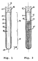
- FIG. 1 A first example of a device according to the invention is described hereinafter with reference to Fig. 1 .
- the container body of the device is a sample tube 11 and a layer 24 of a porous material is arranged within sample tube 11.
- Sample tube 11 has a symmetry axis 13, a cylindrical side wall 15, an upper opening 16, a bottom region 18, and a bottom wall 19.
- the upper opening 16 of sample tube 11 is closed by a cap 21 which is piercable by a pipetting needle.
- the interior of sample tube 11 comprises an upper portion 14 and a lower portion 17.
- the outer surface of layer 24 is in contact with and covers at least partially the inner surface 25 of the cylindrical side wall 15.
- porous material layer 24 covers the entire inner surface 25 of the cylindrical side wall 15.
- Layer 24 of porous material is suitable for retaining non-liquid components 32 of the blood sample 31.
- Layer 24 of porous material is made of e.g. an open cell foam, a foamed rubber, a fleece, a mat, a honeycomb-like material or the like.
- the device comprises in addition a tubular mesh or stent 26 which is in contact with and extends at least partially over the inner surface of layer 24 of porous material.
- tubular mesh or stent 26 extends over the entire inner surface of layer 24 of porous material.
- Tubular mesh or stent 26 is made preferably of a plastic material, e.g. Nylon, Teflon or the like. Tubular mesh or stent 26 keeps layer 24 in place, ensures a better down flow of the liquid component of the blood sample and improves the stability of the physical separation of the liquid component and the non-liquid components of the blood sample.
- a first example of a method according to the invention for separating a liquid component from a blood sample makes use of the device described above with reference to Fig. 1 and comprises the following steps illustrated by Figures 2 to 5 :
- Step (b) is carried out with a rotation speed adjusted to a value in a range between 1000 and 20000 rpm.
- the time required for the separation depends from the rotation speed. A decrease of the time required for the separation is obtained by increasing the rotation speed.
- separation of platelet-free plasma of a blood sample is achieved in a separation time lying in a range from 30 to 60 seconds.
- step (c) a portion of the liquid component of the blood sample can be collected by pipetting through the stopper 21 while the entire non-liquid components of the blood sample 31 and a portion of the liquid component of the blood sample are retained by layer 24 of the porous material.
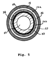
- FIG. 5 shows the spatial distribution of the liquid component 33 and the non-liquid components 32 of blood sample 31 at the end of the axial centrifugation of sample tube 11 according to step (b) but before stopping the rotation of the above described method and as schematically represented by Fig. 3 .
- the non-liquid components 32 occupy an outer annular portion 24a of layer 24 of porous material
- a first portion of the liquid component 33 occupies an inner annular portion 24b of layer 24 of porous material
- a second portion of the liquid component 33 occupies an annular space between tubular mesh 26 and a space 27 occupied by air in the interior of sample tube 11.
- sample tube 11 is a blood collection tube that contains a vacuum, this tube contains a coagulation preventing agent, and the blood sample 31 is introduced into the blood collection tube by venipuncture.
- the liquid component 33 separated by the above described method is blood plasma.
- sample tube 11 is a blood collection tube that contains a vacuum, this tube contains no coagulation preventing agent or contains a coagulation promoting agent, and the blood sample 31 is introduced into the blood collection tube by venipuncture.
- the liquid component 33 separated by the above described method is blood serum.
- sample tube 11 and the separated liquid component 33 contained therein are usually kept at a suitable temperature until sample tube 11 and its contents are transferred to a clinical diagnostic analyzer apparatus for analysis of the liquid component 33.
- the liquid component 33 of the blood sample is pipetted from sample tube 11 by means of a pipetting needle which pierces cap 21, enters sample tube 11 and aspirates the liquid component 33, which is transferred e.g. to a reaction cuvette of the clinical diagnostic analyzer apparatus.
- FIG. 6 A second example of a device according to the invention is described hereinafter with reference to Fig. 6 .
- sample tube 11 shown by Fig. 6 comprises in addition a cup 22, which is fluidically connected with the interior of sample tube 11 through an opening 23 in the bottom wall 19 of sample tube 11.
- Cup 22 is configured and dimensioned for enabling photometric measurement of a liquid contained in cup 22.
- a second example of a method according to the invention for separating a liquid component from a blood sample makes use of the device described above with reference to Fig. 6 and comprises the following steps illustrated by Figures 7 to 9 :
- Step (b) is carried out with a rotation speed adjusted to a value in a range between 1000 and 20000 rpm.
- the time required for the separation depends from the rotation speed. A decrease of the time required for the separation is obtained by increasing the rotation speed.
- separation of platelet-free plasma of a blood sample is achieved in a separation time lying in a range from 30 to 60 seconds.
- step (c) a portion of the liquid component of the blood sample can be collected by pipetting through the stopper 21 while the entire non-liquid components of the blood sample 31 and a portion of the liquid component of the blood sample are retained by layer 24 of the porous material.
- sample tube 11 is a blood collection tube that contains a vacuum, this tube contains a coagulation preventing agent, and the blood sample 31 is introduced into the blood collection tube by venipuncture.
- the portion of the liquid component 33 separated by the above described method and contained in cup 22 is blood plasma.
- sample tube 11 is a blood collection tube that contains a vacuum, this tube contains no coagulation preventing agent or contains a coagulation promoting agent, and the blood sample 31 is introduced into the blood collection tube by venipuncture.
- the portion of the liquid component 33 separated by the above described method and contained in cup 22 is blood serum.
- sample integrity checks including measurement of serum indices can be performed by photometric measurement of the serum sample contained in cup 22.
- sample tube 11 after step (c) is e.g. as described above in the first example of a method according to the invention.
- a first example of an analytical apparatus according to the invention is e.g. a clinical diagnostic analyzer apparatus comprising a device as described above with reference to Fig. 1 and an arrangement for centrifugating the sample tube 11 of such a device about its symmetry axis 13.
- this apparatus comprises a device as described above with reference to Fig. 6 and electro-optical means for performing photometric measurements of the contents of the cup 22 of that device.
- Fig. 10 shows a top plan view of a second embodiment of a device according to the invention.
- Fig. 11 shows a cross-sectional view of the device shown in Fig. 10 taken along a plane A-A.
- Fig. 12 shows a cross-sectional view of the device shown in Fig. 10 taken along a plane B-B in Fig. 11 .
- the third example of a device according to the invention comprises a container body 41 which has a symmetry axis 43.
- the interior of container body 41 is divided into a plurality of compartments 51 to 58 by radially oriented partition walls 91 to 98.
- Each of compartments 51 to 58 is adapted for receiving a blood sample. All compartments 51 to 58 have preferably the same shape and the same size, and the number of compartments is preferably an even number.
- the container is divided into 12 compartments.
- Each one of compartments 51 to 58 has a bottom region like 72 and 76 shown in Fig. 11 .
- container body 41 is a one-piece container body.
- Container body 41 has an upper portion 44 and a lower portion 47.
- the upper portion 44 of container body 41 has a cylindrical side wall 45 and an upper opening 46.
- the lower portion 47 of container body 41 has the shape of a truncated cone and has a conical side wall 48 and a bottom wall 49.
- the device shown by Figures 10 to 12 further comprises a layer 84 of a porous material which is arranged within each of compartments 51 to 58.
- the outer surface of layer 84 is in contact with and covers at least partially the inner surface 85 of the portion of the cylindrical side wall 45 which belongs to that compartment.
- porous material layer 84 covers the entire inner surface of the portion of the cylindrical side wall 45 which belongs to each compartment 51 to 58.
- Layer 84 of porous material is suitable for retaining non-liquid components 32 of the blood sample 31.
- the device shown by Figures 10 to 12 further comprises a cover 82 of the upper opening 46 of container body 41.
- Cover 82 is permanently connected to container body 41.
- Cover 82 has at least one pipetting opening 89 for each of the compartments 51 to 58.
- the at least one pipetting opening 89 allows passage of pipetting needle therethrough for pipetting a blood sample into or out of one of compartments 51-58.
- cover 82 has a first pipetting opening 88 and a second pipetting opening 89 for each of the compartments 51 to 58.
- First pipetting opening 88 allows passage of a pipetting needle therethrough for pipetting a blood sample into one of compartments 51-58.
- Second pipetting opening 89 allows passage of a pipetting needle therethrough for pipetting out of one of compartments 51-58 a liquid component separated from that blood sample.
- Layer 84 of porous material is made of e.g. an open cell foam, a foamed rubber, a fleece, a mat, a honeycomb-like material or the like.
- the device shown by Figures 10 to 12 comprises in addition a mesh or stent 86 which is in contact with and extend at least partially over the inner surface of layer 84 of porous material.
- mesh or stent 86 extends over the entire inner surface of layer 84 of porous material.
- Mesh or stent 86 is made preferably of a plastic material, e.g. nylon or Teflon or the like. Mesh 86 keeps layer 84 in place, ensures a better down flow of the liquid component of the blood sample and improves the stability of the physical separation of the liquid component and the non-liquid components of the blood sample.
- Step (b) is carried out with a rotation speed adjusted to a value in a range between 500 and 10000 rpm.
- the time required for the separation depends from the rotation speed. A decrease of the time required for the separation is obtained by increasing the rotation speed.
- separation of platelet-free plasma of a blood sample is achieved in a separation time lying in a range from 30 to 60 seconds.
- portions of the liquid components 332, 336 of the blood samples can be collected by means of a pipetting needle introduced through the pipetting openings 89 of cover 82 while the entire non-liquid components 322, 326 of the blood samples 312, 316 and portions of the liquid components 332, 336 of the blood samples 312, 316 are retained by layer 84 of the porous material.
- the non-liquid components 322, 326 of the blood sample in any of compartments 51-58 occupy a segment of an outer portion 84a of layer 84 of porous material, whereas a first portion of the liquid components 332, 336 of the blood sample occupies an inner portion 84b of layer 84 of porous material and a second portion of the liquid components occupy spaces each of which lies between mesh 86 and a space occupied by air in the interior of a compartment 51-58 of container body 41.
- each of the blood samples 312, 316 introduced into compartments 52, 56 of container 41 by pipetting through pipetting openings 88 of cover 82 is obtained by means of a blood collection tube that contains a vacuum, this tube contains a coagulation preventing agent, and the blood sample 312, 316 is introduced into the blood collection tube by venipuncture.
- the liquid components 332, 336 separated by the above described method are blood plasma.
- each of the blood samples 312, 316 introduced into compartments 52, 56 of container 41 by pipetting through pipetting openings 88 of cover 82 is obtained by means of a blood collection tube that contains a vacuum, this tube contains no coagulation preventing agent or contains a coagulation promoting agent, and the blood sample 312, 316 is introduced into the blood collection tube by venipuncture.
- the liquid component 332, 336 separated by the above described method is blood serum.
- container body 41 and the separated liquid components 332, 336 contained in the compartments 52, 56 of container body 41 are usually kept at a suitable temperature until container body 41 and its contents are transferred to a clinical diagnostic analyzer apparatus for analysis of the liquid components 332, 336.
- the liquid components 332, 336 of the blood samples are aspirated from the interior of a compartment 51-58 of container body 41 by means of a pipetting needle which is introduced into the compartments of container body through the pipetting openings 89 and aspirates samples of the liquid components 332, 336, and transfers them e.g. to reaction cuvettes of the clinical diagnostic analyzer apparatus.
- step (b) is carried out with a centrifuge which is part of a clinical diagnostic analyzer which has an automatic pipetting unit and the blood samples to be processed are introduced by the latter pipetting unit through openings 88 of cover 82 of container 41 into compartments 52, 56 of this container, and after the separation of the liquid and non-liquid components of the blood samples, the pipetting unit of the analyzer aspirates samples of the liquid components from the lower portions of compartments 52, 56 of container 41, and this samples are analyzed in the clinical diagnostic analyzer.
- step (a) of the above described method a blood sample is loaded into each of the compartments 51-58 of container body 41.
- FIG. 16 A fourth example of a device according to the invention is described hereinafter with reference to Fig. 16 .
- each of the compartments 51-58 of container body 41 comprises in addition a cup 102, 106, which is fluidically connected with the interior of that compartment 52, 56 through an opening 92, 96 in the bottom wall 49 of the container body 41.
- Each of cups 102, 106 is configured and dimensioned for enabling photometric measurement of a liquid contained in that cup. As shown by Fig. 16 , each of cups 102, 106 has plane parallel side walls which extend downwards from opening 92, 96 in the bottom wall of the corresponding compartment 52, 56.
- a mirror 112, 116 is so arranged in each of the cups 102, 106 that when an incident light beam 121, 123 is transmitted towards that cup a light beam 122, 124 is reflected by mirror 112, 116.
- the arrangement of a mirror 112, 116 in each of cups 102, 106 enables a photometric measurement of a liquid contained in that cup 102, 106.
- FIG. 17 shows a front view seen from the direction indicated by arrow 130 of only one of the compartments of the device and shows a cup 132 which is fluidically connected with compartment 52 and which is suitable for performing photometric measurements.
- each of the cups 132 of the device has plane parallel side walls which extend downwards from opening 92 in the bottom wall of the corresponding compartment 52.
- mirrors 141 and 142 are so arranged with respect to each of the cups 132 that when an incident light beam 143 is transmitted towards mirror 141, a corresponding light beam 144 reflected by mirror 141 passes through cup 132 and is reflected by mirror 142 which emits a corresponding reflected light beam 145.
- the arrangement of a mirrors 141, 142 associated with each one of cups 132 enables a photometric measurement of a liquid contained in that cup 132.
- An fourth example of a method according to the invention for separating a liquid component from a blood sample makes use of the device described above with reference to Fig. 16 or a device described above with reference to Fig. 17 and comprises the following steps:
- Step (b) is carried out with a rotation speed adjusted to a value in a range between 500 and 10000 rpm.
- the time required for the separation depends from the rotation speed. A decrease of the time required for the separation is obtained by increasing the rotation speed.
- separation of platelet-free plasma of a blood sample is achieved in a separation time lying in a range from 30 to 60 seconds.
- step (c) a portion of the liquid components 332, 336 of the blood sample can be collected by pipetting through the pipetting openings 89 of cover 82 while the entire non-liquid components 322, 326 of the blood samples 312, 316 and portions of the liquid components 332, 336 of the blood samples 312, 316 are retained by layer 84 of the porous material.
- a portion of the liquid component 332, 336 separated by the above described method is contained in cup 102, 106 or 132 and enables photometric measurements of the liquid component 332, 336 contained in this cup.
- each of the blood samples 312, 316 introduced into compartments 52, 56 of container 41 by pipetting through pipetting openings 88 of cover 82 is obtained by means of a blood collection tube that contains a vacuum, this tube contains a coagulation preventing agent, and the blood sample 312, 316 is introduced into the blood collection tube by venipuncture.
- the liquid component 332, 336 separated by the above described method is blood plasma.
- each of the blood samples 312, 316 introduced into compartments 52, 56 of container 41 by pipetting through pipetting openings 88 of cover 82 is obtained by means of a blood collection tube that contains a vacuum, this tube contains no coagulation preventing agent or contains a coagulation promoting agent, and the blood sample 312, 316 is introduced into the blood collection tube by venipuncture.
- the liquid component 332, 336 separated by the above described method is blood serum.
- step (a) of the above described method a blood sample is loaded into each of the compartments 51-58 of container body 41.
- Sample integrity checks including measurement of serum indices can be performed by photometric measurement of the serum sample contained in cup 102, 106 or 132.
- step (c) The further processing of the contents of container body 41 after step (c) is e.g. as described above in the third example of a method according to the invention.
- a second example of an analytical apparatus according to the invention is e.g. a clinical diagnostic analyzer apparatus comprising a centrifuge to receive the device as described above with reference to Figures 10 to 12 and an arrangement for centrifugating the container body 41 of such a device about its symmetry axis 43.
- this apparatus comprises a device as described above with reference to Figures 16 and 17 and electro-optical means for performing photometric measurements of the contents of the cup 102, 106 or 132 of that device.
Landscapes
- Health & Medical Sciences (AREA)
- Life Sciences & Earth Sciences (AREA)
- Chemical & Material Sciences (AREA)
- General Health & Medical Sciences (AREA)
- Analytical Chemistry (AREA)
- Engineering & Computer Science (AREA)
- Physics & Mathematics (AREA)
- Biochemistry (AREA)
- General Physics & Mathematics (AREA)
- Immunology (AREA)
- Pathology (AREA)
- Hematology (AREA)
- Biomedical Technology (AREA)
- Chemical Kinetics & Catalysis (AREA)
- Ecology (AREA)
- Clinical Laboratory Science (AREA)
- Biophysics (AREA)
- Molecular Biology (AREA)
- Urology & Nephrology (AREA)
- Food Science & Technology (AREA)
- Medicinal Chemistry (AREA)
- Investigating Or Analysing Biological Materials (AREA)
- Centrifugal Separators (AREA)
- Sampling And Sample Adjustment (AREA)
- Investigating Or Analysing Materials By Optical Means (AREA)
Abstract
A device for separating and collecting a liquid component of a blood sample. The device comprises
(a) a container body (11, 41) having a symmetry axis (13, 43) and consisting of
(a.1) an upper portion (14, 44) having a cylindrical side wall (15, 45), and an upper opening (16, 46), and
(a.2) a lower portion (17, 47) having a bottom region (18, 48) and a bottom wall (19, 49), and
(c) a porous material (24, 84) arranged within said container body (11), the outer surface of said porous material (24, 84) being in contact with and covering at least partially the inner surface of said cylindrical side wall (15, 85), said porous material (24, 84) being suitable for retaining non-liquid components (32) of said blood sample (31).
(a) a container body (11, 41) having a symmetry axis (13, 43) and consisting of
(a.1) an upper portion (14, 44) having a cylindrical side wall (15, 45), and an upper opening (16, 46), and
(a.2) a lower portion (17, 47) having a bottom region (18, 48) and a bottom wall (19, 49), and
(c) a porous material (24, 84) arranged within said container body (11), the outer surface of said porous material (24, 84) being in contact with and covering at least partially the inner surface of said cylindrical side wall (15, 85), said porous material (24, 84) being suitable for retaining non-liquid components (32) of said blood sample (31).
Description
- The invention concerns a device for separating a liquid component of a blood sample.
- The invention also concerns a method for separating a liquid component of a blood sample.
- The invention further concerns an analyzer apparatus comprising a device of the above mentioned kind.
- The separation of liquid components of blood samples, e.g. plasma and serum, is a necessary and important part of the preparation of those samples for their processing in modern clinical diagnostic analyzer apparatuses.
- Known methods for performing the above mentioned separation require an important amount of manual work and time. The automation of that manual work would require a high degree of robotic automisation. Moreover the most widely used separation methods are batch processes, i.e. treatment of individual samples is not possible.
- There is therefore a need for a device and a method which overcome the above mentioned drawbacks of prior art in this field.
- A first aim of the invention is to provide a device for separating a liquid component of a blood sample which allows overcoming the above mentioned drawbacks.
- According to a first aspect of the invention the above first aim is achieved by means of a device defined by claim 1.
- Claims 2, 3, 6 to 12 and 18 to 25 define preferred embodiments of this device.
- A second aim of the invention is to provide a method for separating a liquid component of a blood sample which allows overcoming the above mentioned drawbacks.
- According to a second aspect of the invention the above second aim is achieved by methods defined by
claims Claims 15 and 28 define preferred embodiments of those methods. - A third aim of the invention is to provide a clinical diagnostic analyzer apparatus which comprises means for separating a liquid component of a blood sample.
- According to a third aspect of the invention the above third aim is achieved by means of analyzer apparatuses defined by
claims - The main advantages obtained with a device and a method according to the invention are as follows:
- The time required for plasma or serum separation is substantially reduced, because the length of the motion path followed by cell components of blood sample during the axial centrifugation of the sample container by rotation thereof about its symmetry axis is much shorter than in a conventional swing bucket centrifugation of a primary sample tube. When swing bucket centrifugation of a sample tube containing a blood sample is performed the rotation axis is perpendicular to the length axis of the sample tube and the motion path followed by cell components of blood sample during the centrifugation is much longer because the cell components move along the length axis of the sample tube towards the bottom of this tube.
- The centrifugation time necessary for achieving plasma or serum separation with a device according to the invention is shorter than the centrifugation time required in the case of a conventional swing bucket centrifugation of a primary sample tube, because the cell components of the blood sample have to migrate along a shorter distance. In the embodiments shown by
Figures 1 to 9 , wherein the sample container is a sample tube, the migration distance of the cell components of the blood sample is less than half the length of the radius of the cross-section of the sample container. In the embodiments shown byFigures 10 to 17 , the migration distance of the cell components of the blood sample is only about half the distance of the thickness of the layer of blood which is spun to the outer wall of the sample container. - If a primary sample tube is used as a sample container for axial centrifugation according to the invention, the length of the motion path followed by cell components of blood sample during axial centrifugation is much less than the length of the radius of a the primary sample tube, e.g. between 1 and 4 mm.
- The centrifuge required for axial centrifugation of a single sample container is small and is thus suitable for being integrated as an automatically operated centrifuge into an analyzer apparatus even if the space available is relatively small. Such apparatus preferably comprises one such centrifuge for all of the sample containers in the analyzer apparatus.
- Plasma or serum separated by axial centrifugation of a sample container according to the invention is taken out of the sample container by means of the pipetting needle of the automatic pipetting unit of an analyzer apparatus. For this purpose the pipetting needle pierces the plug which closes a primary sample tube if such a tube is used as sample container for axial centrifugation. This process is thus much simpler and faster than the conventional method which requires an additional plasma separating device which has to be manually introduced into the sample tube or uses a built in gel in the primary sample tube. Such a gel is relatively expensive and with this latter method it takes relatively long time, e.g. about 15 minutes, to separate the liquid component from the non-liquid components of the blood sample.
- A preferred embodiment of the sample container includes a cup which is suitable for performing photometric or reflectometric measurements of serum or plasma separated from a blood sample. This embodiment makes thus possible to perform sample integrity checks including measurement of serum indices.
- The above mentioned advantages make it possible to separate a liquid component of a whole blood sample, e.g. plasma or serum, automatically and exclusively with components available in the analyzer apparatus. In this way, all required integrity checks of the blood sample can be carried out automatically in the analyzer apparatus before the usual analysis of plasma or serum samples is carried out in the analyzer apparatus. The compartmented device defined by
claims 18 to 25 makes possible to treat simultaneously a plurality of blood samples in a single container, i.e. to separate the liquid components of those samples with a single centrifugation step. - The subject invention will now be described in terms of its preferred embodiments with reference to the accompanying drawings. These embodiments are set forth to aid the understanding of the invention, but are not to be construed as limiting.
-
Fig. 1 is a cross-sectional view of a first embodiment of a device according to the invention, the cross-section being taken along a plane passing through thesymmetry axis 13 of asample tube 11. -
Fig. 2 is a cross-sectional view of thesample tube 11 like the one shown byFig. 1 and of ablood sample 31 contained insample tube 11. -
Fig. 3 is a cross-sectional view of thesample tube 11 like the one shown byFig. 1 at the end of the axial centrifugation of thesample tube 11, the centrifugation being effected by spinningsample tube 11 about itssymmetry axis 13.Fig. 3 schematically shows the separation of the blood sample into itsnon-liquid components 32 and itsliquid component 33. -
Fig. 4 is a cross-sectional view of thesample tube 11 like the one shown byFig. 1 after axial centrifugation of thesample tube 11 and with this tube at rest. -
Fig. 5 is a cross-sectional, enlarged view ofsample tube 11 shown byFig. 3 , the cross-sectional view being taken along a plane perpendicular to the symmetry axis ofsample tube 11.Fig. 5 shown more in detail the spatial distribution of thenon-liquid components 32 and theliquid component 33 of a blood sample at the end of the axial centrifugation of thesample tube 11, -
Fig. 6 is a cross-sectional view of a variant of the embodiment shown byFig. 1 which comprises acup 22 which is fluidically connected with the interior ofsample tube 11 through an opening 23 in thebottom wall 19 and which is suitable for performing photometric measurements. -
Fig. 7 is a cross-sectional view of thesample tube 11 like the one shown byFig. 6 and of ablood sample 31 contained insample tube 11. -
Fig. 8 is a cross-sectional view of thesample tube 11 like the one shown byFig. 6 at the end of the axial centrifugation of thesample tube 11.Fig. 8 schematically shows the separation of the blood sample into itsnon-liquid components 32 and itsliquid component 33. -
Fig. 9 is a cross-sectional view of thesample tube 11 like the one shown byFig. 6 after axial centrifugation of thesample tube 11 and with this tube at rest. -
Fig. 10 shows a top plan view of a second embodiment of a device according to the invention. -
Fig. 11 shows a cross-sectional view of the device shown inFig. 10 taken along a plane A-A. -
Fig. 12 shows a cross-sectional view of the device shown inFig. 10 taken along a plane B-B inFig. 11 . -
Fig. 13 shows a cross-sectional view of the device shown inFig. 10 taken along a plane A-A and after blood samples have been loaded intocompartments -
Fig. 14 shows a cross-sectional view of the device shown inFig. 10 taken along a plane A-A and at the end of the axial centrifugation ofcontainer body 41, the centrifugation being effected by spinning thecontainer body 41 about itssymmetry axis 43. -
Fig. 15 shows a cross-sectional view of the device shown inFig. 1 taken along a plane A-A after axial centrifugation of this device and with this device at rest. -
Fig. 16 shows a cross-sectional view of a variant of the device shown inFig. 10 .Fig. 16 showscups compartments -
Fig. 17 shows a front view of a variant of the device shown inFig. 16. Fig. 17 shows only one of the compartments of this variant and shows acup 132 which is fluidically connected with acompartment 52 and which is suitable for performing photometric measurements. -
- 11
- primary sample tube
- 13
- symmetry axis of
sample tube 11 / rotation axis for - axial
- centrifugation of
sample tube 11 - 14
- upper portion of
sample tube 11 - 15
- cylindrical side wall of
sample tube 11 - 16
- upper opening of
sample tube 11 - 17
- lower portion of
sample tube 11 - 18
- bottom region of
sample tube 11 - 19
- bottom wall of
sample tube 11 - 21
- cap of
sample tube 11 - 22
- cup connected with the interior of
sample tube 11 - 23
- opening in the
bottom wall 16 ofsample tube 11 - 24
- layer of porous material
- 24a
- outer annular portion of
layer 24 - 24b
- inner annular portion of
layer 24 - 25
- inner surface of
cylindrical side wall 15 - 26
- tubular mesh or stent
- 27
- air
- 31
- blood sample
- 32
- non-liquid components of
blood sample 31 - 33
- liquid component of
blood sample 31 - 41
- container body
- 43
- symmetry axis of
container body 41 / rotation axis for - axial
- centrifugation of
container body 41 - 44
- cylindrical upper portion of
container body 41 - 45
- cylindrical side wall of container body
- 46
- upper opening of
container body 41 - 47
- lower portion of
container body 41 - 48
- conical side wall of
container body 41 - 49
- bottom wall of
container body 41 - 50
- arrow
- 51-58
- compartment of
container body 41 - 61-68
- partition wall of
container body 41 - 72
- bottom region of
compartment 52 - 76
- bottom region of
compartment 56 - 82
- cover of
upper opening 46 ofcontainer body 41 - 84
- layer of porous material
- 84a
- outer portion of
layer 84 - 84 b
- inner portion of
layer 84 - 85
- inner surface of
side wall 45 - 86
- mesh / stent
- 87
- air
- 88
- pipetting opening / piercable pipetting opening
- 89
- pipetting opening / piercable pipetting opening
- 92
- opening in the bottom wall of
compartment 52 - 96
- opening in the bottom wall of
compartment 56 - 102
- cup connected with
compartment 52 - 106
- cup connected with
compartment 56 - 112
- mirror arranged within
cup 102 - 116
- mirror arranged within
cup 106 - 121
- incident light beam
- 122
- reflected light beam
- 123
- incident light beam
- 124
- reflected light beam
- 130
- arrow
- 132
- cup connected with
compartment 52 - 141
- mirror
- 142
- mirror
- 143
- incident light beam
- 144
- reflected light beam
- 145
- reflected light beam
- 312
- blood sample in
compartment 52 - 316
- blood sample in
compartment 56 - 322
- non-liquid component of
blood sample 312 - 326
- non-liquid component of
blood sample 316 - 332
- liquid component of
blood sample 312 - 336
- liquid component of
blood sample 316 - Preferred embodiments are described hereinafter with reference to the accompanying drawings.
- In general terms a device according to the invention for separating and collecting a liquid component of a blood sample comprises a container body and a porous material arranged within the container body. The container body has a symmetry axis and consists of an upper portion having a cylindrical side wall and an upper opening, and a lower portion having a bottom region and a bottom wall. The outer surface of the porous material is in contact with and covers at least partially the inner surface of the cylindrical side wall of the upper portion of the container body. The porous material is suitable for retaining
non-liquid components 32 of theblood sample 31. - In a preferred embodiment the container body of the device is a one-piece container body.
- In a preferred embodiment, the above mentioned device further comprises a mesh or stent which is in contact with and extends at least partially over the inner surface of the layer of porous material.
- In general terms a method according to the invention for separating and collecting a liquid component of a blood sample comprises
- (a) introducing a blood sample into container body of a device of the above described type,
- (b) rotating said container body about its symmetry axis at a predetermined speed for separating the liquid component of the blood sample from the non-liquid components thereof, and
- (c) stopping said rotating of said container body, thereby allowing the liquid component of the blood sample to flow towards the central and lower part of the container body, whereas the entire non-liquid components of the blood sample and a portion of the liquid component of the blood sample are retained by the layer of porous material.
- In general terms a clinical diagnostic analyzer apparatus according to the invention comprises
- (a) a device of the above described type, and
- (b) means for centrifugating the container body of said device about its symmetry axis (13, 43).
- A first example of a device according to the invention is described hereinafter with reference to
Fig. 1 . - As shown by
Fig. 1 , in this first example the container body of the device is asample tube 11 and alayer 24 of a porous material is arranged withinsample tube 11. -
Sample tube 11 has asymmetry axis 13, acylindrical side wall 15, anupper opening 16, abottom region 18, and abottom wall 19. Theupper opening 16 ofsample tube 11 is closed by acap 21 which is piercable by a pipetting needle. The interior ofsample tube 11 comprises anupper portion 14 and alower portion 17. - The outer surface of
layer 24 is in contact with and covers at least partially theinner surface 25 of thecylindrical side wall 15. In a preferred embodimentporous material layer 24 covers the entireinner surface 25 of thecylindrical side wall 15. -
Layer 24 of porous material is suitable for retainingnon-liquid components 32 of theblood sample 31. -
Layer 24 of porous material is made of e.g. an open cell foam, a foamed rubber, a fleece, a mat, a honeycomb-like material or the like. - In a preferred embodiment the device comprises in addition a tubular mesh or
stent 26 which is in contact with and extends at least partially over the inner surface oflayer 24 of porous material. In a preferred embodiment, tubular mesh orstent 26 extends over the entire inner surface oflayer 24 of porous material. - Tubular mesh or
stent 26 is made preferably of a plastic material, e.g. Nylon, Teflon or the like. Tubular mesh orstent 26 keepslayer 24 in place, ensures a better down flow of the liquid component of the blood sample and improves the stability of the physical separation of the liquid component and the non-liquid components of the blood sample. - A first example of a method according to the invention for separating a liquid component from a blood sample makes use of the device described above with reference to
Fig. 1 and comprises the following steps illustrated byFigures 2 to 5 : - (a) introducing a blood sample 31 (shown in
Fig. 2 ) into thesample tube 11, - (b)
rotating sample tube 11 about its symmetry axis 13 (as shown byFigures 3 and5 ) at a predetermined speed for separating the liquid component of the blood sample from the non-liquid components thereof, and - (c) stopping the rotating of
sample tube 11, thereby allowing the liquid component of the blood sample to flow towards the central and lower part of thesample tube 11, whereas the entire non-liquid components of theblood sample 31 and a portion of the liquid component of the blood sample are retained bylayer 24 of the porous material. - Step (b) is carried out with a rotation speed adjusted to a value in a range between 1000 and 20000 rpm. The time required for the separation depends from the rotation speed. A decrease of the time required for the separation is obtained by increasing the rotation speed. In the case of centrifugation of the
sample tube 11 the following are examples of rotation speeds used and of the values of the separation time achieved:Rotation speed 1000 rpm 20000 rpm Separation time 20 minutes 15 seconds. - With a rotation speed of 20000 rpm, separation of platelet-free plasma of a blood sample is achieved in a separation time lying in a range from 30 to 60 seconds.
- After step (c) a portion of the liquid component of the blood sample can be collected by pipetting through the
stopper 21 while the entire non-liquid components of theblood sample 31 and a portion of the liquid component of the blood sample are retained bylayer 24 of the porous material. - The cross-sectional view shown by
Fig. 5 shows the spatial distribution of theliquid component 33 and thenon-liquid components 32 ofblood sample 31 at the end of the axial centrifugation ofsample tube 11 according to step (b) but before stopping the rotation of the above described method and as schematically represented byFig. 3 . As shown byFig. 5 , thenon-liquid components 32 occupy an outer annular portion 24a oflayer 24 of porous material, whereas a first portion of theliquid component 33 occupies an innerannular portion 24b oflayer 24 of porous material and a second portion of theliquid component 33 occupies an annular space betweentubular mesh 26 and aspace 27 occupied by air in the interior ofsample tube 11. - In one embodiment of the above described method,
sample tube 11 is a blood collection tube that contains a vacuum, this tube contains a coagulation preventing agent, and theblood sample 31 is introduced into the blood collection tube by venipuncture. In this case theliquid component 33 separated by the above described method is blood plasma. - In another embodiment of the above described method,
sample tube 11 is a blood collection tube that contains a vacuum, this tube contains no coagulation preventing agent or contains a coagulation promoting agent, and theblood sample 31 is introduced into the blood collection tube by venipuncture. In this case theliquid component 33 separated by the above described method is blood serum. - After step (c)
sample tube 11 and the separatedliquid component 33 contained therein are usually kept at a suitable temperature untilsample tube 11 and its contents are transferred to a clinical diagnostic analyzer apparatus for analysis of theliquid component 33. For this purpose, theliquid component 33 of the blood sample is pipetted fromsample tube 11 by means of a pipetting needle which piercescap 21, enterssample tube 11 and aspirates theliquid component 33, which is transferred e.g. to a reaction cuvette of the clinical diagnostic analyzer apparatus. - A second example of a device according to the invention is described hereinafter with reference to
Fig. 6 . - The structure of this second example is a variant of the structure of the example shown by
Fig. 1 . In this variant,sample tube 11 shown byFig. 6 comprises in addition acup 22, which is fluidically connected with the interior ofsample tube 11 through anopening 23 in thebottom wall 19 ofsample tube 11.Cup 22 is configured and dimensioned for enabling photometric measurement of a liquid contained incup 22. - A second example of a method according to the invention for separating a liquid component from a blood sample makes use of the device described above with reference to
Fig. 6 and comprises the following steps illustrated byFigures 7 to 9 : - (a) introducing a blood sample 31 (shown in
Fig. 7 ) into sample tube 11 (shown inFig. 6 ), - (b)
rotating sample tube 11 about itssymmetry axis 13 at a predetermined speed for separating the liquid component of theblood sample 31 from the non-liquid components thereof (as shown byFig. 8 ), and - (c) stopping the rotating of
sample tube 11, thereby allowing the liquid component of the blood sample to flow towards the central and lower part of thesample tube 11 and intocup 22, whereas the entirenon-liquid components 32 of theblood sample 31 and a portion of theliquid component 33 of the blood sample are retained bylayer 24 of the porous material. - Step (b) is carried out with a rotation speed adjusted to a value in a range between 1000 and 20000 rpm. The time required for the separation depends from the rotation speed. A decrease of the time required for the separation is obtained by increasing the rotation speed. In the case of centrifugation of the
sample tube 11 the following are examples of rotation speeds used and of the values of the separation time achieved:Rotation speed 1000 rpm 20000 rpm Separation time 20 minutes 15 seconds. - With a rotation speed of 20000 rpm, separation of platelet-free plasma of a blood sample is achieved in a separation time lying in a range from 30 to 60 seconds.
- After step (c) a portion of the liquid component of the blood sample can be collected by pipetting through the
stopper 21 while the entire non-liquid components of theblood sample 31 and a portion of the liquid component of the blood sample are retained bylayer 24 of the porous material. - In this second example of a method according to the invention a portion of the
liquid component 33 separated by the above described method is contained incup 22 and enables photometric measurements of theliquid component 33 contained in this cup. - In one embodiment of the above described method,
sample tube 11 is a blood collection tube that contains a vacuum, this tube contains a coagulation preventing agent, and theblood sample 31 is introduced into the blood collection tube by venipuncture. In this case the portion of theliquid component 33 separated by the above described method and contained incup 22 is blood plasma. - In another embodiment of the above described method,
sample tube 11 is a blood collection tube that contains a vacuum, this tube contains no coagulation preventing agent or contains a coagulation promoting agent, and theblood sample 31 is introduced into the blood collection tube by venipuncture. In this case the portion of theliquid component 33 separated by the above described method and contained incup 22 is blood serum. - In this case, sample integrity checks including measurement of serum indices can be performed by photometric measurement of the serum sample contained in
cup 22. - The further processing of
sample tube 11 after step (c) is e.g. as described above in the first example of a method according to the invention. - A first example of an analytical apparatus according to the invention is e.g. a clinical diagnostic analyzer apparatus comprising a device as described above with reference to
Fig. 1 and an arrangement for centrifugating thesample tube 11 of such a device about itssymmetry axis 13. - In a preferred embodiment of this apparatus it comprises a device as described above with reference to
Fig. 6 and electro-optical means for performing photometric measurements of the contents of thecup 22 of that device. - A third example of a device according to the invention is described hereinafter with reference to
Figures 10 to 12 . -
Fig. 10 shows a top plan view of a second embodiment of a device according to the invention. -
Fig. 11 shows a cross-sectional view of the device shown inFig. 10 taken along a plane A-A. -
Fig. 12 shows a cross-sectional view of the device shown inFig. 10 taken along a plane B-B inFig. 11 . - As shown by
Figures 10 to 12 , the third example of a device according to the invention comprises acontainer body 41 which has asymmetry axis 43. As shown byFig. 12 , the interior ofcontainer body 41 is divided into a plurality ofcompartments 51 to 58 by radially oriented partition walls 91 to 98. Each ofcompartments 51 to 58 is adapted for receiving a blood sample. Allcompartments 51 to 58 have preferably the same shape and the same size, and the number of compartments is preferably an even number. In a preferred embodiment the container is divided into 12 compartments. Each one ofcompartments 51 to 58 has a bottom region like 72 and 76 shown inFig. 11 . In a preferredembodiment container body 41 is a one-piece container body. -
Container body 41 has anupper portion 44 and alower portion 47. Theupper portion 44 ofcontainer body 41 has acylindrical side wall 45 and anupper opening 46. Thelower portion 47 ofcontainer body 41 has the shape of a truncated cone and has a conical side wall 48 and abottom wall 49. - The device shown by
Figures 10 to 12 further comprises alayer 84 of a porous material which is arranged within each ofcompartments 51 to 58. The outer surface oflayer 84 is in contact with and covers at least partially theinner surface 85 of the portion of thecylindrical side wall 45 which belongs to that compartment. In a preferred embodimentporous material layer 84 covers the entire inner surface of the portion of thecylindrical side wall 45 which belongs to eachcompartment 51 to 58. -
Layer 84 of porous material is suitable for retainingnon-liquid components 32 of theblood sample 31. - The device shown by
Figures 10 to 12 further comprises acover 82 of theupper opening 46 ofcontainer body 41.Cover 82 is permanently connected tocontainer body 41.Cover 82 has at least onepipetting opening 89 for each of thecompartments 51 to 58. The at least onepipetting opening 89 allows passage of pipetting needle therethrough for pipetting a blood sample into or out of one of compartments 51-58. In apreferred embodiment cover 82 has afirst pipetting opening 88 and a second pipetting opening 89 for each of thecompartments 51 to 58. First pipettingopening 88 allows passage of a pipetting needle therethrough for pipetting a blood sample into one of compartments 51-58.Second pipetting opening 89 allows passage of a pipetting needle therethrough for pipetting out of one of compartments 51-58 a liquid component separated from that blood sample. -
Layer 84 of porous material is made of e.g. an open cell foam, a foamed rubber, a fleece, a mat, a honeycomb-like material or the like. - In a preferred embodiment the device shown by
Figures 10 to 12 comprises in addition a mesh orstent 86 which is in contact with and extend at least partially over the inner surface oflayer 84 of porous material. In a preferred embodiment, mesh orstent 86 extends over the entire inner surface oflayer 84 of porous material. - Mesh or
stent 86 is made preferably of a plastic material, e.g. nylon or Teflon or the like.Mesh 86 keepslayer 84 in place, ensures a better down flow of the liquid component of the blood sample and improves the stability of the physical separation of the liquid component and the non-liquid components of the blood sample. - An third example of a method according to the invention for separating a liquid component from a blood sample makes use of the device described above with reference to
Figures 10 to 12 and comprises the following steps illustrated byFigures 13 to 15 which show compartments 52 and 56 of container body 41: - (a) introducing
blood samples 312, 316 (shown inFig. 13 ) intorespective compartments container body 41 of a device according to the above described third example of a device according to the invention, - (b) rotating the
container body 41 about its symmetry axis 43 (as shown byFig. 14 ) at a predetermined speed and in a sense shown byarrow 50 for separating theliquid components blood samples non-liquid components - (c) stopping the rotating of the
container body 41, thereby allowing theliquid components blood samples bottom regions respective compartments 52 respectively 56 of thecontainer body 41, whereas the entirenon-liquid components blood samples liquid components blood samples layer 84 of the porous material. - Step (b) is carried out with a rotation speed adjusted to a value in a range between 500 and 10000 rpm. The time required for the separation depends from the rotation speed. A decrease of the time required for the separation is obtained by increasing the rotation speed. In the case of centrifugation of the
container body 41 the following are examples of rotation speeds used and of the values of the separation time achieved:Rotation speed 500 rpm 10000 rpm Separation time 20 minutes 15 seconds. - With a rotation speed of 10000 rpm, separation of platelet-free plasma of a blood sample is achieved in a separation time lying in a range from 30 to 60 seconds.
- After step (c) portions of the
liquid components pipetting openings 89 ofcover 82 while the entirenon-liquid components blood samples liquid components blood samples layer 84 of the porous material. - The spatial distribution of the
liquid component 33 and thenon-liquid components 32 ofblood sample 31 during axial centrifugation ofcontainer body 41 according to step (b) of the above described method and as schematically represented byFig. 14 is similar to the spatial distribution shown byFig. 5 for the where container body is asample tube 11 with the only difference that the interior ofcontainer body 41 is subdivided in compartments 51-58, whereas the interior ofsample tube 11 is not. At the end of the axial centrifugation ofcontainer body 41 according to step (b), thenon-liquid components outer portion 84a oflayer 84 of porous material, whereas a first portion of theliquid components inner portion 84b oflayer 84 of porous material and a second portion of the liquid components occupy spaces each of which lies betweenmesh 86 and a space occupied by air in the interior of a compartment 51-58 ofcontainer body 41. - In one embodiment of the above described method, each of the
blood samples compartments container 41 by pipetting throughpipetting openings 88 ofcover 82 is obtained by means of a blood collection tube that contains a vacuum, this tube contains a coagulation preventing agent, and theblood sample liquid components - In another embodiment of the above described method, each of the
blood samples compartments container 41 by pipetting throughpipetting openings 88 ofcover 82 is obtained by means of a blood collection tube that contains a vacuum, this tube contains no coagulation preventing agent or contains a coagulation promoting agent, and theblood sample liquid component - After step (c)
container body 41 and the separatedliquid components compartments container body 41 are usually kept at a suitable temperature untilcontainer body 41 and its contents are transferred to a clinical diagnostic analyzer apparatus for analysis of theliquid components liquid components container body 41 by means of a pipetting needle which is introduced into the compartments of container body through thepipetting openings 89 and aspirates samples of theliquid components - In a preferred embodiment, step (b) is carried out with a centrifuge which is part of a clinical diagnostic analyzer which has an automatic pipetting unit and the blood samples to be processed are introduced by the latter pipetting unit through
openings 88 ofcover 82 ofcontainer 41 intocompartments compartments container 41, and this samples are analyzed in the clinical diagnostic analyzer. - In a preferred embodiment, in step (a) of the above described method a blood sample is loaded into each of the compartments 51-58 of
container body 41. - A fourth example of a device according to the invention is described hereinafter with reference to
Fig. 16 . - The structure of this fourth example is similar to the structure of the third example described above with reference to
Figures 10 to 12 , but in this fourth example each of the compartments 51-58 ofcontainer body 41 comprises in addition acup compartment opening bottom wall 49 of thecontainer body 41. Each ofcups Fig. 16 , each ofcups corresponding compartment - In a preferred embodiment of the device shown by
Fig. 16 amirror cups incident light beam 121, 123 is transmitted towards that cup alight beam mirror mirror cups cup - A fifth example of a device according to the invention is described hereinafter with reference to
Fig. 17 . This fifth is a variant of the device shown inFig. 16. Fig. 17 shows a front view seen from the direction indicated byarrow 130 of only one of the compartments of the device and shows acup 132 which is fluidically connected withcompartment 52 and which is suitable for performing photometric measurements. - As shown by
Fig. 17 , each of thecups 132 of the device has plane parallel side walls which extend downwards from opening 92 in the bottom wall of thecorresponding compartment 52. - In a preferred embodiment of the device shown by
Fig. 17 mirrors cups 132 that when an incident light beam 143 is transmitted towardsmirror 141, a correspondinglight beam 144 reflected bymirror 141 passes throughcup 132 and is reflected bymirror 142 which emits a corresponding reflectedlight beam 145. The arrangement of amirrors cups 132 enables a photometric measurement of a liquid contained in thatcup 132. - An fourth example of a method according to the invention for separating a liquid component from a blood sample makes use of the device described above with reference to
Fig. 16 or a device described above with reference toFig. 17 and comprises the following steps: - (a) introducing
blood samples 312, 316 (as shown inFig. 13 ) intorespective compartments container body 41 of a device according to the above described third example of a device according to the invention, - (b) rotating the
container body 41 about its symmetry axis 43 (as shown byFig. 14 ) at a predetermined speed and in a sense shown byarrow 50 for separating theliquid components blood samples non-liquid components - (c) stopping the rotating of the
container body 41, thereby allowing theliquid components blood samples bottom regions cups respective compartments container body 41, whereas the entirenon-liquid components blood samples liquid components blood samples layer 84 of the porous material. - Step (b) is carried out with a rotation speed adjusted to a value in a range between 500 and 10000 rpm. The time required for the separation depends from the rotation speed. A decrease of the time required for the separation is obtained by increasing the rotation speed. In the case of centrifugation of the
container body 41 the following are examples of rotation speeds used and of the values of the separation time achieved:Rotation speed 500 rpm 10000 rpm Separation time 20 minutes 15 seconds. - With a rotation speed of 10000 rpm, separation of platelet-free plasma of a blood sample is achieved in a separation time lying in a range from 30 to 60 seconds.
- After step (c) a portion of the
liquid components pipetting openings 89 ofcover 82 while the entirenon-liquid components blood samples liquid components blood samples layer 84 of the porous material. - In this fourth example of a method according to the invention a portion of the
liquid component cup liquid component - In one embodiment of the above described method, each of the
blood samples compartments container 41 by pipetting throughpipetting openings 88 ofcover 82 is obtained by means of a blood collection tube that contains a vacuum, this tube contains a coagulation preventing agent, and theblood sample liquid component - In another embodiment of the above described method, each of the
blood samples compartments container 41 by pipetting throughpipetting openings 88 ofcover 82 is obtained by means of a blood collection tube that contains a vacuum, this tube contains no coagulation preventing agent or contains a coagulation promoting agent, and theblood sample liquid component - In a preferred embodiment, in step (a) of the above described method a blood sample is loaded into each of the compartments 51-58 of
container body 41. - Sample integrity checks including measurement of serum indices can be performed by photometric measurement of the serum sample contained in
cup - The further processing of the contents of
container body 41 after step (c) is e.g. as described above in the third example of a method according to the invention. - A second example of an analytical apparatus according to the invention is e.g. a clinical diagnostic analyzer apparatus comprising a centrifuge to receive the device as described above with reference to
Figures 10 to 12 and an arrangement for centrifugating thecontainer body 41 of such a device about itssymmetry axis 43. - In a preferred embodiment of this apparatus it comprises a device as described above with reference to
Figures 16 and 17 and electro-optical means for performing photometric measurements of the contents of thecup - Although preferred embodiments of the invention have been described using specific terms, such description is for illustrative purposes only, and it is to be understood that changes and variations obvious to the skilled artisan are to be considered within the scope and spirit of the subject application, which is only to be limited by the claims that follow and their equivalents.
Claims (30)
- A device for separating and collecting a liquid component of a blood sample, said device comprising(a) a container body (11, 41) having a symmetry axis (13, 43) and consisting of(a.1) an upper portion (14, 44) having a cylindrical side wall (15, 45), and an upper opening (16, 46), and(a.2) a lower portion (17, 47) having a bottom region (18, 48) and a bottom wall (19, 49), and(c) a layer of porous material (24, 84) arranged within said container body (11), the outer surface of said porous material (24, 84) being in contact with and covering at least partially the inner surface of said cylindrical side wall (15, 85), said porous material (24, 84) being suitable for retaining non-liquid components (32) of said blood sample (31, 312).
- A device according to claim 1, wherein said container body is a one-piece container body.
- A device according to claim 1, said device further comprising a mesh or stent (26, 86) which is in contact with and extends at least partially over the inner surface of said of layer of porous material (24, 84).
- A method of separating a liquid component from a blood sample, said method comprising:(a) introducing a blood sample (31) into container body (11, 41) of a device according to any of claims 1 to 3(b) rotating said container body (11, 41) about its symmetry axis (13, 43) at a predetermined speed for separating the liquid component (33) of the blood sample (31) from the non-liquid components (32) thereof, and(c) stopping said rotating of said container body (11, 41), thereby allowing the liquid component of the blood sample to flow towards the central and lower part of the container body (11, 41), whereas the entire non-liquid components (32) of the blood sample (31) and a portion of the liquid component (33) of the blood sample (31) are retained by the layer (24) of porous material.
- A clinical diagnostic analyzer apparatus comprising(a) a device according to any of claims 1 to 3, and(b) means for centrifugating said container body (11, 41) of said device about its symmetry axis (13, 43).
- A device according to any of claims 1 to 3, wherein said container body is a sample tube (11), said sample tube (11) having a symmetry axis (13), a cylindrical side wall (15), an upper opening (16), a bottom region (18), and a bottom wall (19),
said device further comprising(a) a cap (21) which closes the upper opening (16) of said sample tube (11), said cap being piercable by a pipetting needle, and(b) a layer (24) of a porous material arranged within said sample tube (11), the outer surface of said layer (24) being in contact with and covering at least partially the inner surface (25) of said cylindrical side wall (15), said layer (24) of porous material being suitable for retaining non-liquid components (32) of said blood sample. - A device according to claim 6, wherein said layer (24) of porous material is made of an open cell foam, a foamed rubber, a fleece, a mat, a honeycomb-like material or the like.
- A device according to any of claims 6 or 7, said device further comprising a tubular mesh or stent (26) which is in contact with and extends at least partially over the inner surface of said layer (24) of porous material.
- A device according to claim 8, wherein said tubular mesh or stent (26) is made of a plastic material.
- A device according to any of claims 6 to 9, wherein said sample tube (11) contains a coagulation preventing agent.
- A device according to any of claims 6 to 9, wherein said sample tube (11) contains a coagulation promoting agent.
- A device according to any of claims 6 to 11, wherein said device further comprises a cup (22), which is fluidically connected with the interior of sample tube (11) through an opening (23) in the bottom wall (19) of the sample tube (11), said cup (22) being configured and dimensioned for enabling photometric measurement of a liquid contained in said cup (22).
- A method of separating a liquid component from a blood sample, said method comprising:(a) introducing a blood sample (31) into the sample tube (11) of a device according to any of claims 6 to 11(b) rotating said sample tube (11) about its symmetry axis (13) at a predetermined speed for separating the liquid component (33) of the blood sample (31) from the non-liquid components (32) thereof, and(c) stopping said rotating of said sample tube (11), thereby allowing the liquid component of the blood sample to flow towards the central and lower part of the sample tube (11), whereas the entire non-liquid components (32) of the blood sample (31) and a portion of the liquid component (33) of the blood sample (31) are retained by the layer (24) of porous material.
- A method for separating a liquid component from a blood sample, said method comprising:(a) introducing a blood sample (31) into a sample tube (11) of a device according to claim 12,(b) rotating said sample tube (11) about its symmetry axis (13) at a predetermined speed for separating the liquid component (33) of the blood sample (31) from the non-liquid components (32) thereof, and(c) stopping said rotating of said sample tube (11), thereby allowing the liquid component of the blood sample to flow towards the central and lower part of the sample tube (11) and into said cup (22), whereas the entire non-liquid components (32) of the blood sample (31) and a portion of the liquid component (33) of the blood sample (31) are retained by the layer (24) of porous material.
- A method for carrying out sample integrity checks including measurement of serum indices of a blood sample, said method comprising(a) separating the serum component of said blood sample (31) by a method according to any of claims 13 or 14, and(b) effecting a photometric measurement of the serum sample contained in a cup (22) of a device according to claim 12.
- A clinical diagnostic analyzer apparatus comprising(a) a device according to any of claims 6 to 12, and(b) means for centrifugating the sample tube (11) of said device about its symmetry axis (13).
- A clinical diagnostic analyzer apparatus comprising(a) a device according to claim 12,(b) a centrifuge for centrifugating the sample tube (11) of said device about its symmetry axis (13), and(c) electro-optical means for performing photometric measurements of the contents of the cup (22) of said device.
- A device according to any of claims 1 to 3, said device comprising(a) a container body (41) having a symmetry axis (43) and consisting of(a.1) an upper portion (44), said upper portion having a cylindrical side wall (45) and an upper opening (46), and(a.2) a lower portion (47) having the shape of a truncated cone, said lower portion having and a conical side wall (48) and a bottom wall (49),the interior of said container body (41) being divided into a plurality of compartments (51-58) by radially oriented partition walls (91-98), each of said compartments (52, 56) having a bottom region (72, 76),(b) a layer (84) of a porous material arranged within each of said compartments (51-58), the outer surface of said layer (84) being in contact with and covering at least partially the inner surface (85) of the portion of said cylindrical side wall (45) which belongs to said compartment, said layer (84) of porous material being suitable for retaining non-liquid components (32) of said blood sample, and(c) a cover (82) of the said upper opening (46) of said container body (41), said cover (82) being permanently connected to said container body (41), and said cover (82) having for each of said compartments (51-58) at least one pipetting opening (88, 89) which allows passage of a pipetting needle therethrough for pipetting a blood sample into said compartment (51-58) and for pipetting out of said compartment (51-58) said liquid component of that blood sample (332-338).
- A device according to claim 18, wherein said container body is a one-piece container body.
- A device according to claim any of claims 18 or 19, wherein said layer (84) of porous material is made of an open cell foam, a foamed rubber, a fleece, a mat, a honeycomb-like material or the like.
- A device according to any of claims 18 to 20, said device further comprising a mesh or stent (86) which is in contact with and extends at least partially over the inner surface of said layer (84) of porous material.
- A device according to claim 21, wherein said mesh or stent (86) is made of a plastic material.
- A device according to any of claims 18 to 22, wherein each of said compartments (52, 56) of said container body (41) contains a coagulation preventing agent.
- A device according to any of claims 18 to 22, wherein each of said compartments (52, 56) of said container body (41) contains a coagulation promoting agent.
- A device according to any of claims 18 to 24, wherein said device further comprises a plurality of cups (102, 106), each of which is located below one of the compartments (52, 56) of said container body (41) and is fluidically connected with the interior of said compartment (52, 56)through an opening (91-98) in the bottom wall (49) of the lower portion (45) of said container body (41), said cups (102, 106) being configured and dimensioned for enabling a photometric measurement of a liquid contained therein.
- A method for separating a liquid component from a blood sample, said method comprising:(a) introducing blood samples (312, 316) into respective compartments (52, 56)of the container body (41) of a device according to any of claims 18 to 24,(b) rotating the container body (41) about its symmetry axis (43) at a predetermined speed for separating the liquid components (332, 336) of the blood samples (312, 316) from the non-liquid components (322, 326) thereof, and(c) stopping the rotating of the container body (41), thereby allowing the liquid components (332, 336) of the blood samples (312, 316) to flow towards the central and bottom regions (72, 76) of the respective compartments (52, 56) of the container body (41), whereas the entire non-liquid components (322, 326) of the blood samples (312, 316) and a portion of the liquid components (332, 336) of the blood samples (312, 316) are retained by layer (84) of the porous material.
- A method for separating a liquid component from a blood samples, said method comprising:(a) introducing blood samples (312, 316) into respective compartments (52, 56) of the container body (41) of the device of claim 25,(b) rotating the container body (41) about its symmetry axis (43) at a predetermined speed for separating the liquid components (332, 336) of the blood samples (312, 316) from the non-liquid components (322, 326) thereof, and(c) stopping the rotating of the container body (41), thereby allowing the liquid components (332, 336) of the blood samples (312, 316) to flow towards the central and bottom regions (72, 76) and into said cups (102, 106, 132) of the respective compartments (52, 56) of the container body (41), whereas the entire non-liquid components (322, 326) of the blood samples (312, 316) and portions of the liquid components (332, 336) of the blood samples (312, 316) are retained by layer (84) of the porous material.
- A method for carrying out sample integrity checks including measurement of serum indices of a blood sample, said method comprising(a) separating the serum component of said blood sample (312, 316) by a method according to claim 27, and(b) effecting a photometric measurement of the serum sample contained in a cup (102, 106, 132) of a device according to claim 23.
- A clinical diagnostic analyzer apparatus comprising(a) a device according to any of claims 18 to 24, and(b) means for centrifugating the container body (41) of said device about the symmetry axis (43) of said container body (41).
- A clinical diagnostic analyzer apparatus comprising(a) a device according to claim 25,(b) means for centrifugating the container body (41) of said device about the symmetry axis (43) of said container body (41), and(c) electro-optical means for performing photometric measurements of the contents of the cups (102, 106, 132) of said device.
Priority Applications (6)
| Application Number | Priority Date | Filing Date | Title |
|---|---|---|---|
| EP07001572A EP1949962A1 (en) | 2007-01-25 | 2007-01-25 | Device and method for separating a liquid component of a blood sample, and analyzer apparatus comprising such a device |
| EP08707285A EP2107946A2 (en) | 2007-01-25 | 2008-01-25 | Device and method for separating a liquid component of a blood sample, and analyzer apparatus comprising such a device |
| PCT/EP2008/000575 WO2008089993A2 (en) | 2007-01-25 | 2008-01-25 | Device and method for separating a liquid component of a blood sample, and analyzer apparatus comprising such a device |
| JP2009546686A JP2010517022A (en) | 2007-01-25 | 2008-01-25 | Apparatus and method for separating liquid components of a blood sample, and analytical apparatus comprising such an apparatus |
| US12/506,323 US8040505B2 (en) | 2007-01-25 | 2009-07-21 | Device and method for separating a liquid component of a blood sample, and analyzer apparatus comprising such a device |
| JP2011257653A JP5442699B2 (en) | 2007-01-25 | 2011-11-25 | Apparatus and method for separating liquid components of a blood sample, and analytical apparatus comprising such an apparatus |
Applications Claiming Priority (1)
| Application Number | Priority Date | Filing Date | Title |
|---|---|---|---|
| EP07001572A EP1949962A1 (en) | 2007-01-25 | 2007-01-25 | Device and method for separating a liquid component of a blood sample, and analyzer apparatus comprising such a device |
Publications (1)
| Publication Number | Publication Date |
|---|---|
| EP1949962A1 true EP1949962A1 (en) | 2008-07-30 |
Family
ID=38179560
Family Applications (2)
| Application Number | Title | Priority Date | Filing Date |
|---|---|---|---|
| EP07001572A Withdrawn EP1949962A1 (en) | 2007-01-25 | 2007-01-25 | Device and method for separating a liquid component of a blood sample, and analyzer apparatus comprising such a device |
| EP08707285A Withdrawn EP2107946A2 (en) | 2007-01-25 | 2008-01-25 | Device and method for separating a liquid component of a blood sample, and analyzer apparatus comprising such a device |
Family Applications After (1)
| Application Number | Title | Priority Date | Filing Date |
|---|---|---|---|
| EP08707285A Withdrawn EP2107946A2 (en) | 2007-01-25 | 2008-01-25 | Device and method for separating a liquid component of a blood sample, and analyzer apparatus comprising such a device |
Country Status (4)
| Country | Link |
|---|---|
| US (1) | US8040505B2 (en) |
| EP (2) | EP1949962A1 (en) |
| JP (2) | JP2010517022A (en) |
| WO (1) | WO2008089993A2 (en) |
Families Citing this family (7)
| Publication number | Priority date | Publication date | Assignee | Title |
|---|---|---|---|---|
| US7850917B2 (en) * | 2008-03-11 | 2010-12-14 | Ortho-Clinical Diagnostics, Inc. | Particle agglutination in a tip |
| WO2014050021A1 (en) * | 2012-09-28 | 2014-04-03 | 富士フイルム株式会社 | Centrifugation container |
| JP5936576B2 (en) * | 2013-03-29 | 2016-06-22 | 富士フイルム株式会社 | Centrifuge container, centrifuge, and centrifuge method using them |
| WO2017023949A1 (en) * | 2015-08-04 | 2017-02-09 | Theranos, Inc. | Transfer vessel and methods for reducing sample loss |
| US10484286B2 (en) * | 2016-02-02 | 2019-11-19 | King Fadh University Of Petroleum And Minerals | Adaptive reliability protocol |
| US12127555B2 (en) * | 2020-04-08 | 2024-10-29 | Biolife Solutions, Inc. | Shock absorbing device to protect cryopreserved biological material |
| CN115283037A (en) * | 2021-09-09 | 2022-11-04 | 上海臻诺生物科技有限公司 | Centrifuge tube with good tightness |
Citations (11)
| Publication number | Priority date | Publication date | Assignee | Title |
|---|---|---|---|---|
| US3982691A (en) * | 1974-10-09 | 1976-09-28 | Schlutz Charles A | Centrifuge separation and washing device and method |
| US4042337A (en) * | 1977-02-17 | 1977-08-16 | Griffith Donald P | Urine collection device |
| GB2007546A (en) * | 1977-11-01 | 1979-05-23 | Union Carbide Corp | Disposable rotatable starshaped enclosure for use with blood washing apparatus |
| US4509941A (en) * | 1983-11-14 | 1985-04-09 | Miles Laboratories, Inc. | Fractionation device and method |
| DE3823572C1 (en) * | 1988-07-12 | 1989-06-01 | Eppendorf - Netheler - Hinz Gmbh, 2000 Hamburg, De | Multiple cuvette arrangement for an analysis system |
| WO1994002833A1 (en) * | 1992-07-16 | 1994-02-03 | Spectrum Systems, Inc. | Cuvette and cuvette cartridge for a chemical analyzer |
| US5308506A (en) * | 1987-04-03 | 1994-05-03 | Mcewen James A | Apparatus and method for separating a sample of blood |
| WO1997012679A1 (en) * | 1995-10-03 | 1997-04-10 | Beckman Instruments, Inc. | Axial spin blood separation system and method |
| EP0926483A2 (en) * | 1997-12-25 | 1999-06-30 | Kowa Co., Ltd. | Vessel for imaging fluorescent particles |
| US6302836B1 (en) * | 1998-10-01 | 2001-10-16 | Howard L. North, Jr. | Method for partitioning blood and delivering clean serum |
| US6444174B1 (en) * | 2000-01-24 | 2002-09-03 | Laboratoire Soludia | Cartridge for the preparation of a solution for medical use |
Family Cites Families (16)
| Publication number | Priority date | Publication date | Assignee | Title |
|---|---|---|---|---|
| US4197287A (en) * | 1977-06-10 | 1980-04-08 | Ventrex Laboratories Inc. | Method and apparatus for performing in nitro clinical diagnostic tests using a solid phase assay system having special utility for use with automatic pipetting equipment |
| US4981585A (en) * | 1985-11-14 | 1991-01-01 | Norfolk Scientific, Inc. | Centrifuge system and fluid container therefor |
| US4933291A (en) * | 1986-12-22 | 1990-06-12 | Eastman Kodak Company | Centrifugable pipette tip and pipette therefor |
| US4865106A (en) * | 1987-10-26 | 1989-09-12 | Wichelman Karl F | Heat insulator window shade |
| US4957637A (en) * | 1988-05-23 | 1990-09-18 | Sherwood Medical Company | Serum separator system for centrifuge with piercable membrane |
| US4954264A (en) * | 1989-02-02 | 1990-09-04 | Becton-Dickinson And Company | Apparatus for separating mononuclear cells from blood and method of manufacturing and using the same |
| EP0558473A1 (en) * | 1989-11-08 | 1993-09-08 | Fmc Corporation | Combined centrifuge tube and porous selection means for separation and recovery of biological materials |
| US5275731A (en) * | 1991-06-28 | 1994-01-04 | Jahn Karl H | Apparatus for rapidly separating blood into filtered fractions |
| JPH08304387A (en) * | 1995-04-28 | 1996-11-22 | Aloka Co Ltd | Blood sampling device |
| JP3132342B2 (en) * | 1995-07-07 | 2001-02-05 | 松下電器産業株式会社 | Specimen test method and device |
| US5935051A (en) * | 1997-08-29 | 1999-08-10 | Beckman Instruments, Inc. | Blood separation device |
| US6291249B1 (en) * | 1999-03-02 | 2001-09-18 | Qualigen, Inc. | Method using an apparatus for separation of biological fluids |
| EP1162463B1 (en) * | 2000-06-10 | 2003-08-27 | Becton Dickinson and Company | Collection device for blood |
| WO2005011830A2 (en) * | 2003-07-25 | 2005-02-10 | Nagaoka & Co., Ltd. | Fluidic circuits for sample preparation including bio-discs and methods relating thereto |
| JP2006242872A (en) * | 2005-03-04 | 2006-09-14 | Kyocera Corp | Separation apparatus and measurement apparatus provided with the separation apparatus |
| DE602005010083D1 (en) * | 2005-09-21 | 2008-11-13 | Roche Diagnostics Gmbh | Reagent container assembly and analyzer with such arrangement |
-
2007
- 2007-01-25 EP EP07001572A patent/EP1949962A1/en not_active Withdrawn
-
2008
- 2008-01-25 EP EP08707285A patent/EP2107946A2/en not_active Withdrawn
- 2008-01-25 JP JP2009546686A patent/JP2010517022A/en active Pending
- 2008-01-25 WO PCT/EP2008/000575 patent/WO2008089993A2/en not_active Ceased
-
2009
- 2009-07-21 US US12/506,323 patent/US8040505B2/en not_active Expired - Fee Related
-
2011
- 2011-11-25 JP JP2011257653A patent/JP5442699B2/en not_active Expired - Fee Related
Patent Citations (11)
| Publication number | Priority date | Publication date | Assignee | Title |
|---|---|---|---|---|
| US3982691A (en) * | 1974-10-09 | 1976-09-28 | Schlutz Charles A | Centrifuge separation and washing device and method |
| US4042337A (en) * | 1977-02-17 | 1977-08-16 | Griffith Donald P | Urine collection device |
| GB2007546A (en) * | 1977-11-01 | 1979-05-23 | Union Carbide Corp | Disposable rotatable starshaped enclosure for use with blood washing apparatus |
| US4509941A (en) * | 1983-11-14 | 1985-04-09 | Miles Laboratories, Inc. | Fractionation device and method |
| US5308506A (en) * | 1987-04-03 | 1994-05-03 | Mcewen James A | Apparatus and method for separating a sample of blood |
| DE3823572C1 (en) * | 1988-07-12 | 1989-06-01 | Eppendorf - Netheler - Hinz Gmbh, 2000 Hamburg, De | Multiple cuvette arrangement for an analysis system |
| WO1994002833A1 (en) * | 1992-07-16 | 1994-02-03 | Spectrum Systems, Inc. | Cuvette and cuvette cartridge for a chemical analyzer |
| WO1997012679A1 (en) * | 1995-10-03 | 1997-04-10 | Beckman Instruments, Inc. | Axial spin blood separation system and method |
| EP0926483A2 (en) * | 1997-12-25 | 1999-06-30 | Kowa Co., Ltd. | Vessel for imaging fluorescent particles |
| US6302836B1 (en) * | 1998-10-01 | 2001-10-16 | Howard L. North, Jr. | Method for partitioning blood and delivering clean serum |
| US6444174B1 (en) * | 2000-01-24 | 2002-09-03 | Laboratoire Soludia | Cartridge for the preparation of a solution for medical use |
Also Published As
| Publication number | Publication date |
|---|---|
| WO2008089993A3 (en) | 2008-10-02 |
| JP5442699B2 (en) | 2014-03-12 |
| JP2010517022A (en) | 2010-05-20 |
| WO2008089993A2 (en) | 2008-07-31 |
| US20100011887A1 (en) | 2010-01-21 |
| JP2012058256A (en) | 2012-03-22 |
| US8040505B2 (en) | 2011-10-18 |
| EP2107946A2 (en) | 2009-10-14 |
Similar Documents
| Publication | Publication Date | Title |
|---|---|---|
| US3901658A (en) | Whole blood analysis rotor assembly having removable cellular sedimentation bowl | |
| US5149501A (en) | Multichambered container and instrument for performing diagnostic tests | |
| US5853600A (en) | Axial spin blood separation system and method | |
| CA1296693C (en) | Apparatus and method for separating phases of blood | |
| US5354483A (en) | Double-ended tube for separating phases of blood | |
| JPH04227080A (en) | Device for centrifugally separating uneven liquid sample suitable for separation of blood plasma from blood | |
| EP0272915B1 (en) | Centrifugable pipette tip and pipette therefor | |
| US5419835A (en) | Flow restrictor-separation device | |
| ES2583643T3 (en) | Computer-implemented method to operate an automated sample work cell | |
| EP0608006A2 (en) | Analytical rotors and methods for analysis of biological fluids | |
| US3926521A (en) | Blood collecting and processing means | |
| US5275731A (en) | Apparatus for rapidly separating blood into filtered fractions | |
| EP3411709B1 (en) | An arrangement for collection and separation of a body fluid for purposes of analysis and a method relating thereto | |
| US4104025A (en) | Method of preparing liquid samples for testing | |
| US8040505B2 (en) | Device and method for separating a liquid component of a blood sample, and analyzer apparatus comprising such a device | |
| WO1993008893A1 (en) | Sample metering port for analytical rotor | |
| JP2000506419A (en) | Sample container for blood collection | |
| EP2879581B1 (en) | Biological liquid collection vessels | |
| JP7361492B2 (en) | Laboratory systems and methods for separating interfering substances contained in test samples | |
| CA1219469A (en) | Liquid sampling apparatus with retention means | |
| CA2347669C (en) | Analytical rotors and methods for analysis of biological fluids | |
| JP7733073B2 (en) | Separation inserts and separation devices | |
| US20240382869A1 (en) | Spin column | |
| JPH0743362A (en) | Sample container and automatic analyzer using this sample container | |
| JPH0299865A (en) | Method and device for automatically generating and evaluating agglutination reaction in order to mainly detecting slight agglutination |
Legal Events
| Date | Code | Title | Description |
|---|---|---|---|
| PUAI | Public reference made under article 153(3) epc to a published international application that has entered the european phase |
Free format text: ORIGINAL CODE: 0009012 |
|
| AK | Designated contracting states |
Kind code of ref document: A1 Designated state(s): AT BE BG CH CY CZ DE DK EE ES FI FR GB GR HU IE IS IT LI LT LU LV MC NL PL PT RO SE SI SK TR |
|
| AX | Request for extension of the european patent |
Extension state: AL BA HR MK RS |
|
| AKX | Designation fees paid | ||
| REG | Reference to a national code |
Ref country code: DE Ref legal event code: 8566 |
|
| STAA | Information on the status of an ep patent application or granted ep patent |
Free format text: STATUS: THE APPLICATION IS DEEMED TO BE WITHDRAWN |
|
| 18D | Application deemed to be withdrawn |
Effective date: 20090131 |