EP1949924A1 - Treatment device for endoscope and double tube for the treatment device - Google Patents
Treatment device for endoscope and double tube for the treatment device Download PDFInfo
- Publication number
- EP1949924A1 EP1949924A1 EP06811974A EP06811974A EP1949924A1 EP 1949924 A1 EP1949924 A1 EP 1949924A1 EP 06811974 A EP06811974 A EP 06811974A EP 06811974 A EP06811974 A EP 06811974A EP 1949924 A1 EP1949924 A1 EP 1949924A1
- Authority
- EP
- European Patent Office
- Prior art keywords
- tube
- outer tube
- inner tube
- therapeutic device
- endoscopic
- Prior art date
- Legal status (The legal status is an assumption and is not a legal conclusion. Google has not performed a legal analysis and makes no representation as to the accuracy of the status listed.)
- Withdrawn
Links
Images


Classifications
-
- A—HUMAN NECESSITIES
- A61—MEDICAL OR VETERINARY SCIENCE; HYGIENE
- A61M—DEVICES FOR INTRODUCING MEDIA INTO, OR ONTO, THE BODY; DEVICES FOR TRANSDUCING BODY MEDIA OR FOR TAKING MEDIA FROM THE BODY; DEVICES FOR PRODUCING OR ENDING SLEEP OR STUPOR
- A61M5/00—Devices for bringing media into the body in a subcutaneous, intra-vascular or intramuscular way; Accessories therefor, e.g. filling or cleaning devices, arm rests
- A61M5/14—Infusion devices, e.g. infusing by gravity; Blood infusion; Accessories therefor
-
- A—HUMAN NECESSITIES
- A61—MEDICAL OR VETERINARY SCIENCE; HYGIENE
- A61B—DIAGNOSIS; SURGERY; IDENTIFICATION
- A61B17/00—Surgical instruments, devices or methods
- A61B17/34—Trocars; Puncturing needles
- A61B17/3478—Endoscopic needles, e.g. for infusion
-
- A—HUMAN NECESSITIES
- A61—MEDICAL OR VETERINARY SCIENCE; HYGIENE
- A61B—DIAGNOSIS; SURGERY; IDENTIFICATION
- A61B1/00—Instruments for performing medical examinations of the interior of cavities or tubes of the body by visual or photographical inspection, e.g. endoscopes; Illuminating arrangements therefor
-
- A—HUMAN NECESSITIES
- A61—MEDICAL OR VETERINARY SCIENCE; HYGIENE
- A61B—DIAGNOSIS; SURGERY; IDENTIFICATION
- A61B1/00—Instruments for performing medical examinations of the interior of cavities or tubes of the body by visual or photographical inspection, e.g. endoscopes; Illuminating arrangements therefor
- A61B1/012—Instruments for performing medical examinations of the interior of cavities or tubes of the body by visual or photographical inspection, e.g. endoscopes; Illuminating arrangements therefor characterised by internal passages or accessories therefor
- A61B1/018—Instruments for performing medical examinations of the interior of cavities or tubes of the body by visual or photographical inspection, e.g. endoscopes; Illuminating arrangements therefor characterised by internal passages or accessories therefor for receiving instruments
-
- A—HUMAN NECESSITIES
- A61—MEDICAL OR VETERINARY SCIENCE; HYGIENE
- A61M—DEVICES FOR INTRODUCING MEDIA INTO, OR ONTO, THE BODY; DEVICES FOR TRANSDUCING BODY MEDIA OR FOR TAKING MEDIA FROM THE BODY; DEVICES FOR PRODUCING OR ENDING SLEEP OR STUPOR
- A61M25/00—Catheters; Hollow probes
- A61M25/0067—Catheters; Hollow probes characterised by the distal end, e.g. tips
- A61M25/0082—Catheter tip comprising a tool
- A61M25/0084—Catheter tip comprising a tool being one or more injection needles
Definitions
- the present invention relates to an endoscopic therapeutic device, such as an endoscopic injector, which is introduced into a body cavity through a channel of an endoscope and injects a medicine into a tissue part in the body cavity, and to a double tube for the therapeutic device.
- an endoscopic therapeutic device such as an endoscopic injector
- a therapeutic device is introduced into a body cavity through a channel of an endoscope, and a diseased part in the body cavity, for instance, is subjected to various medical treatments.
- Jpn. Pat. Appln. KOKAI Publication No. 2001-58006 discloses an injector, as an example of an endoscopic therapeutic device, which injects a liquid medicine into, for instance, a diseased part in the body cavity.
- the endoscopic injector is provided with an elongated insertion section which is to be inserted into the channel of the endoscope, and an operation section which is coupled to a proximal end portion of the insertion section.
- the insertion section includes a double tube which comprises an outer tube and an inner tube that is advancibly/retreatably inserted in the outer tube.
- the operation section performs an advancing/retreating operation of the inner and outer tubes.
- a hollow needle body is attached to a distal end portion of the inner tube.
- the insertion section of the endoscopic injector is introduced into the body cavity through the channel of the endoscope.
- the inner tube is advanced/retreated, relative to the outer tube, by the operation of the operation section.
- the needle body at the distal end of the inner tube is projected from the distal end portion of the outer tube, or is retreated.
- the needle body is projected from the distal end of the outer tube, thereby puncturing a tissue part in the body cavity.
- PTFE or nylon which has a low surface frictional resistance, is generally used as a material of the outer tube and inner tube.
- the above-mentioned patent document 1 discloses the use of a fluororesin tube or a nylon tube.
- the duct shapes in the lumen in the human body are variously bent ones.
- the insertion section of the endoscope is bent in various shapes in accordance with the duct shape in the body cavity.
- the insertion section of the endoscopic injector is also bent in various shapes in accordance with the shape of the insertion section of the endoscope.
- treatment by the endoscopic therapeutic device in the body is, in many cases, performed in the state in which the insertion section of the endoscopic therapeutic device is bent in accordance with the shape of the insertion section of the endoscope.
- the frictional resistance considerably increases at the time of pushing the inner tube and projecting the needle body from the distal end of the outer tube. Consequently, the operation of pushing the inner tube becomes unsmooth.
- the operability of the endoscopic injector deteriorates, and it becomes difficult to stably perform treatment for a disease, leading to a possible increase in time for treatment.
- the present invention has been made in consideration of the above-described circumstances, and the object of the invention is to provide an endoscopic therapeutic device such as an endoscopic injector, and a double tube for the therapeutic device, which have good operability, for example, in an operation of projecting a needle, and can perform a stable operation for a disease, even when treatment is performed in the state in which an insertion section that is inserted in the body is bent.
- an endoscopic therapeutic device such as an endoscopic injector
- a double tube for the therapeutic device which have good operability, for example, in an operation of projecting a needle, and can perform a stable operation for a disease, even when treatment is performed in the state in which an insertion section that is inserted in the body is bent.
- an endoscopic therapeutic device comprising: an insertion section which is inserted in a channel of an endoscope, the insertion section including a double tube having an outer tube and an inner tube which is advancibly/retreatably inserted in the outer tube; and an operation section which is coupled to a proximal end portion of the insertion section and performs an advancing/retreating operation of the inner and outer tubes, wherein the double tube is configured such that at least the inner tube and the outer tube are formed of different kinds of plastic materials, and the outer tube is formed of a material with a higher rigidity than a material of the inner tube.
- the inner tube and the outer tube are formed of different kinds of plastic materials
- the outer tube is formed of a material with a higher rigidity than a material of the inner tube.
- the frictional resistance increases due to the phenomenon that the inner tube is strongly rubbed on the inner side of the outer tube which is bent at the time of the operation of projecting the needle by advancing the inner tube relative to the outer tube.
- the frictional resistance is greatly influenced by the characteristics of the surfaces that are put in sliding contact.
- the outer peripheral surface of the inner tube and the inner peripheral surface of the outer tube, which are put in sliding contact with each other have mutually close atomic bond states, and these surfaces have high affinity. As a result, the frictional resistance increases.
- the hardness of the inner tube is set to be lower than that of the outer tube of the double tube, and the materials of at least the sliding surfaces of the outer tube and inner tube are made different.
- the sliding frictional resistance at the time of advancing/retreating the inner and outer tubes in the state in which the inner and outer tubes are bent can be reduced.
- the outer tube has a higher bending elasticity modulus than the inner tube.
- the outer tube has a higher bending elasticity modulus than the inner tube.
- the plastic materials are different kinds of polyolefin plastics, of which the outer tube and the inner tube are formed, respectively.
- the outer tube and the inner tube are formed of different kinds of polyolefin plastics. Therefore, the sliding frictional resistance at the time of advancing/retreating the inner and outer tubes in the state in which the inner and outer tubes are bent can be reduced.
- the plastic materials are a polyolefin plastic and a fluoroplastic, of which the outer tube and the inner tube are formed, respectively.
- the outer tube is formed of polypropylene and the inner tube is formed of polyethylene.
- the outer tube is formed of polypropylene and the inner tube is formed of polyethylene.
- the outer tube is formed of polypropylene and the inner tube is formed of PFA.
- a hollow needle body is attached to a distal end of the inner tube, and the operation section includes a needle body operation section which projects the needle body at the distal end of the inner tube to an outside from a distal end portion of the outer tube, and which retreats the needle body.
- the hollow needle body at the distal end of the inner tube is projected to an outside from the distal end portion of the outer tube, and is retreated, by the needle body operation section of the operation section.
- each of a linear thermal expansion coefficient of the outer tube and a linear thermal expansion coefficient of the inner tube is 20 X 10 -5 /°C or less, and a difference between the respective linear thermal expansion coefficients is 5 X 10 -5 /°C or less.
- a double tube for a therapeutic device which includes an outer tube and an inner tube which is advancibly/retreatably inserted in the outer tube, wherein the double tube is configured such that at least the inner tube and the outer tube are formed of different kinds of plastic materials, and the outer tube is formed of a material with a higher rigidity than a material of the inner tube.
- At least the inner tube and the outer tube of the double tube for the therapeutic device are formed of different kinds of plastic materials, and the outer tube is formed of a material with a higher rigidity than a material of the inner tube.
- the frictional resistance increases due to the phenomenon that the inner tube is strongly rubbed on the inner side of the outer tube which is bent at the time of the operation of projecting the needle by advancing the inner tube relative to the outer tube.
- the frictional resistance is greatly influenced by the characteristics of the surfaces that are put in sliding contact.
- the outer peripheral surface of the inner tube and the inner peripheral surface of the outer tube, which are put in sliding contact with each other have mutually close atomic bond states, and these surfaces have high affinity. As a result, the frictional resistance increases.
- the hardness of the inner tube is set to be lower than that of the outer tube of the double tube, and the materials of at least the sliding surfaces of the outer tube and inner tube are made different.
- the sliding frictional resistance at the time of advancing/retreating the inner and outer tubes in the state in which the inner and outer tubes are bent can be reduced.
- the outer tube has a higher bending elasticity modulus than the inner tube.
- the outer tube of the double tube for the therapeutic device has a higher bending elasticity modulus than the inner tube.
- the plastic materials are different kinds of polyolefin plastics, of which the outer tube and the inner tube are formed, respectively.
- the outer tube and the inner tube of the double tube for the therapeutic device are formed of different kinds of polyolefin plastics. Therefore, the sliding frictional resistance at the time of advancing/retreating the inner and outer tubes in the state in which the inner and outer tubes are bent can be reduced.
- the plastic materials are a polyolefin plastic and a fluoroplastic, of which the outer tube and the inner tube are formed, respectively.
- the outer tube is formed of polypropylene and the inner tube is formed of polyethylene.
- the outer tube of the double tube for the therapeutic device is formed of polypropylene and the inner tube is formed of polyethylene.
- the outer tube is formed of polypropylene and the inner tube is formed of PFA.
- the present invention can provide an endoscopic therapeutic device such as an endoscopic injector, and a double tube for a therapeutic device, which have a good operability of, for example, an operation of projecting a needle, and can perform a stable operation for a diseased part, even in the case where medical treatment is performed in the state in which the insertion section that is inserted in the body is bent.
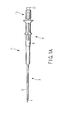
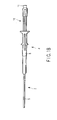
- FIG. 1A and FIG. 1B show an endoscopic injector 1 according to the present embodiment.
- the endoscopic injector 1 includes an elongated insertion section 3 which is inserted in a channel of an endoscope 2 (see FIG. 3 ) and is inserted into the body through the channel, and an operation section 4 which is coupled to a proximal end portion of the insertion section 3.
- the insertion section 3 includes a double tube which comprises an outer tube 5 and an inner tube 6 that is advancible/retreatable in the outer tube 5. Further, a pipe-shaped needle body 7 is attached to a distal end of the inner tube 6. A pointed puncture portion 7a, which is obliquely cut at an angle of, e.g. 30°, is formed at a needle tip of the needle body 7.
- At least the inner tube 6 and outer tube 5 are formed of different kinds of plastic materials, and the outer tube 5 is formed of a material with a higher rigidity than a material of the inner tube 6.
- the outer tube 5 be formed of a plastic material with a higher bending elasticity modulus than a material of the inner tube 6.
- the outer tube 5 and inner tube 6 be formed of different polyolefin plastics.
- the outer tube 5 be formed of polypropylene (PP), and the inner tube 6 be formed of low-density polyethylene (LDPE).
- the outer tube 5 has an inside diameter of ⁇ 1.8 mm and an outside diameter of ⁇ 2.3 mm.
- the inner tube 6 has an inside diameter of ⁇ 0.7 mm and an outside diameter of ⁇ 1.5 mm.
- the needle body 7 is formed of stainless steel material (SUS304).
- the operation section 4 is composed of an operation section body 8 which is fixed to a proximal end portion of the outer tube 5, and a mouthpiece unit 10 which is attached to a proximal end of the inner tube 6 via a stainless-steel pipe 9. As shown in FIG. 2C , the stainless-steel pipe 9 is fixed to a distal end portion of the mouthpiece unit 10 by insert molding. A mouthpiece 11 is formed at a proximal end of the mouthpiece unit 10.
- the operation section body 8 and mouthpiece unit 10 are advancible/retreatable.
- the needle body 7 projects from a distal end opening 13 of the outer tube 5, as shown in FIG. 2A . If the mouthpiece unit 10 is pulled to the proximal side, relative to the operation section body 8, as shown in FIG. 1B and FIG. 2C , the needle body 7 is accommodated in the outer tube 5, as shown in FIG. 2B .
- an engaging abutment portion 12 which is formed of an edge portion projecting radially inward of the outer tube 5, is formed integral with the outer tube 5 in a collar shape by thermal molding. Since the engaging abutment portion 12 is formed in a collar shape, the distal end opening 13 of the outer tube 5, which is formed at the center of the engaging abutment portion 12, is smaller than the inside diameter of the outer tube 5, and the distal end opening 13 is larger than the outside diameter of the needle body 7.
- a stepped cylindrical engaging member 14 having a large-diameter portion 14a and a small-diameter portion 14b is fixed on the outer periphery of the needle body 7 by means of so-called caulking (caulking by tightening in plural (2 to 4) directions).
- the outside diameter of the large-diameter portion 14a is less than the inside diameter of the outer tube 5 and is greater than the diameter of the distal end opening 13.
- restriction means is constituted.
- the inside diameter of the small-diameter portion 14b of the engaging member 14 is substantially equal to the inside diameter of the inner tube 6.
- a distal end portion of the inner tube 6 is tightly fitted on the outer periphery of the small-diameter portion 14b.
- This fitting coupling part is fixed by an adhesive 15.
- the engaging member 14 is a member which fills a clearance between the outside diameter (outer periphery) of the needle body 7 and the inside diameter (inner periphery) of the inner tube 6.
- the inner tube 6 and the needle body 7 are coupled via the engaging member 14.
- the adhesive 15 is coated so as to also cover a part of the outer peripheral surface of the needle body 7, beyond the proximal end face of the engaging member 14. Thereby, the inner tube 6 and engaging member 14 are bonded and at the same time water-tightness between the needle body 7 and engaging member 14 is ensured.
- FIG. 3 shows an example of an endoscope 2 in which the endoscopic injector 1 according to the first embodiment is inserted.
- the endoscope 2 includes an elongated insertion section 16 which is inserted into the body, and an operation section 17 which is coupled to a proximal end portion of the insertion section 16.
- the insertion section 16 includes an elongated flexible tube section 18, a bending section 19 having a proximal end portion coupled to the distal end of the flexible tube section 18, and a distal-end rigid section 20 having a proximal end portion coupled to the distal end of the bending section 19.
- a distal end face of the distal-end rigid section 20 is provided with an illumination optical system, an observation optical system, a distal end opening portion of a therapeutic device insertion channel and an air-feed/water-feed nozzle, which are all not shown.
- the bending section 19 is configured to be bendable from a normal straight state as indicated by a dot-and-dash line in FIG. 3 to a bent state as indicated by a solid line or a two-dot-and-dash line in FIG. 3 .
- the operation section 17 is coupled to a proximal end portion of the flexible tube section 18.
- the operation section 17 is provided with a grasping section 21 which is grasped by a surgeon.
- a proximal end portion of a universal cord 22 is coupled to the grasping section 21.
- the grasping section 21 is provided with an up-and-down bending operation knob 24 and a right-and-left bending operation knob 25 for bend-operating the bending section 19, a suction button 26, an air-feed/water-feed button 27, various switches 28 for endoscopic photography, and a therapeutic device insertion section 29.
- the therapeutic device insertion section 29 is provided with a therapeutic device insertion hole 30 communicating with a proximal end portion of the therapeutic device insertion channel that is provided in the insertion section 16.
- the insertion section 3 of the endoscopic injector 1 is inserted into the therapeutic device insertion channel from the therapeutic device insertion hole 30 of the endoscope 2, and is pushed to the distal-end rigid section 20, and then the insertion section 3 is projected outward from the distal end opening portion of the therapeutic device insertion channel.
- the mouthpiece unit 10 is pulled to the movement limit position on the proximal side, relative to the operation section body 8, and the needle body 7 is set in the state in which the needle body 7 is accommodated in the outer tube 5 (the state shown in FIGS. 1B , 2B and 2C .
- the insertion section 3 of the endoscopic injector 1 is inserted in the therapeutic device insertion channel of the endoscope 2 that is inserted in the body cavity in advance. Then, the distal end portion of the outer tube 5 of the insertion section 3 is projected into the body cavity from the distal end of the endoscope.
- the mouthpiece unit 10 is pushed relative to the operation section body 8, and the needle body 7 is fixed in the state in which the needle body 7 projects from the distal end of the outer tube 5 (the state shown in FIG. 1A and FIG. 2A ).
- the mouthpiece unit 10 is pushed in by holding the operation section body 8 at the proximal part of the outer tube 5 of the endoscopic injector 1, which is out of the proximal end portion of the therapeutic device insertion channel of the endoscope 2.
- the needle body 7 is made to pierce a target tissue, and a medicine, for instance, is fed by a syringe, which is attached to the mouthpiece 11 in advance, and is injected into the tissue to perform medical treatment.
- the insertion section 3 of the endoscopic injector 1 is inserted into the body through the therapeutic device insertion channel of the endoscope 2.
- the endoscopic injector 1 is operated in the state in which the insertion section 3 of the endoscopic injector 1 is bent in accordance with the shape of the insertion section 16 of the endoscope 2.
- the sliding resistance at the time when the inner tube 6 and outer tube 5 are advanced/retreated in the bent state occurs because the outer tube 5 is collapsed and pushed on the inner tube 6 when the inner tube 6 and outer tube 5 are bent.
- the frictional resistance increases due to the phenomenon that the inner tube 6 is strongly rubbed on the inner side of the outer tube 5 which is bent at the time of the operation of projecting the needle body 7 by advancing the inner tube 6 relative to the outer tube 5.
- the outer peripheral surface of the inner tube 6 and the inner peripheral surface of the outer tube 5, which are put in sliding contact with each other, have mutually close atomic bond states, and these surfaces have high affinity.
- the frictional resistance increases.
- the frictional resistance is greatly influenced by the characteristics of the surfaces that are put in sliding contact.
- the hardness of the double tube of the insertion section 3 of the endoscopic injector 1 the hardness of the inner tube 6 is set to be lower than that of the outer tube 5, and the materials of at least the sliding surfaces of the outer tube 5 and inner tube 6 are made different. Thereby, the frictional resistance at the time of bending can be decreased.
- the measurement of the operation force amount of the double tube for the therapeutic device, which is assembled in the insertion section 3 of the endoscopic injector 1 according to the present embodiment, was conducted as follows.
- the inner tube 6 is advanced/retreated in the outer tube 5 in the state in which the insertion section 3 of the endoscopic injector 1 is inserted in the therapeutic device insertion channel of the endoscope 2.
- the endoscope 2 is held in a bent state in which the flexible tube section 18 of the insertion section 16 is wound by a single loop with a proper diameter (e.g. a radius R of 50 mm).
- the insertion section 3 of the endoscopic injector 1 is inserted in the therapeutic device insertion channel from the therapeutic device insertion hole 30 of the endoscope 2 and is operated and pushed to the distal-end rigid section 20, and the insertion section 3 is set in the state in which the insertion section 3 projects from the distal end opening of the therapeutic device insertion channel. In this state, the work for measuring the operation force amount of the double tube for the therapeutic device of the insertion section 3 of the endoscopic injector 1 is conducted.
- the force amount of sliding is measured with the amount of projection of the needle body 7 being set at, e.g. 30 mm.
- Table 1 shows a measurement result of the operation force amount (N) of the double tube for the therapeutic device of the insertion section 3 of the endoscopic injector 1 in the case where the combination of the plastic material of the inner tube 6 and the plastic material of the outer tube 5 of the double tube for the therapeutic device of the insertion section 3 of the endoscopic injector 1 is varied.
- Table 1 No. of experiment Outer tube Inner tube Operation force amount (N) 1 PP PP 7.15 2 HDPE HDPE 10 or more 3 PTFE PTFE 5.62 4 HDPE PP 4.94 5 PP LDPE 0.25 6 PP LLDPE 0.80 7 PP PFA 0.24
- the data of the double tube for the therapeutic device which was used in the measurement experiment of the operation force amount (N) of the double tube for the therapeutic device, is as follows:
- Table 2 shows the characteristics of the materials which were used in the measurement of the operation force amount (N) of the double tube for the therapeutic device.
- Table 2 Material Bending elasticity modulus Hardness PP 1500 MPa R100 PTFE 550 MPa D55 HDPE 1050 MPa D67 LDPE 130 MPa D49 LLDPE 330 MPa D53
- R Rockwell hardness
- D Shore hardness
- HDPE high-density polyethylene
- LLDPE linear low-density polyethylene
- the operation force amount (N) of the double tube for the therapeutic device As indicated in the measurement experiment result in Table 2 of the operation force amount (N) of the double tube for the therapeutic device, in the case where the outer tube 5 and inner tube 6 are formed of the same material as in the cases of experiment Nos. 1 to 3, the operation force amount (N) is relatively high, namely, 7.15, 10 or more, and 5.62. In the case where the hardness of the outer tube 5 is lower than that of the inner tube 6, as in the case of experiment No. 4, the operation force amount (N) is 4.94 and is also high.
- the operation force amount (N) is relatively low, namely, 0.25 and 0.80. It is thus confirmed that the operation force amount is smaller in the case where the hardness of the inner tube 6 is lower than that of the outer tube 5 (experiment Nos. 5 and 6) than in the case where the inner tube 6 and outer tube 5 are formed of the same material (experiment Nos. 1 to 3) or in the case where the hardness of the outer tube 5 is lower than that of the inner tube 6 (experiment No. 4).
- the operation force amount (N) can be decreased in the case where the hardness of the inner tube 6 is lower than that of the outer tube 5.
- the operation force amount (N) decreased to 0.55.
- the inner tube 6 and outer tube 5 are formed of different kinds of plastic materials, and the outer tube 5 is formed of a material with a higher rigidity than a material of the inner tube 6.
- the operation section 4 is operated and the operation of projecting the needle body 7 is performed by advancing the inner tube 6 relative to the outer tube 5 in the state in which the insertion section 3 of the endoscopic injector 1 is bent, the magnitude of the sliding frictional resistance between the inner tube 6 and the outer tube 5 can be reduced.
- the linear thermal expansion coefficient varies accordingly.
- the needle body 7 projects from the distal end opening 13 of the outer tube 5 due to thermal variation (thermal expansion) even at times when there is no need.
- the needle body 7 may not smoothly project.
- the temperature of the environment of use of the endoscopic injector 1 is about 36°C since the endoscopic injector 1 is used in the body.
- the temperature of the environment of the therapeutic treatment room is, in general, about 25 to 28°C.
- the difference between the temperature of the environment of the therapeutic treatment room and the temperature of the environment of use in the body is about 10°C.
- the linear thermal expansion coefficient is so set as to prevent occurrence of problems in projection/retreat of the needle body 7 due to linear thermal expansion or contraction at these temperatures.
- the difference between the linear thermal expansion coefficient of the material of the inner tube 6 and the linear thermal expansion coefficient of the material of the outer tube 5 is set at 5 X 10 -5 /°C or less.
- the linear thermal expansion coefficient of the material of each of the inner tube 6 and outer tube 5 be set at 20 X 10 -5 /°C or less.
- the present invention is effective in a technical field of using an endoscopic therapeutic device such as an endoscopic injector, and a double tube for a therapeutic device, and in a technical field of manufacturing the endoscopic therapeutic device such as an endoscopic injector, and the double tube for a therapeutic device.
Landscapes
- Health & Medical Sciences (AREA)
- Life Sciences & Earth Sciences (AREA)
- Surgery (AREA)
- Animal Behavior & Ethology (AREA)
- General Health & Medical Sciences (AREA)
- Engineering & Computer Science (AREA)
- Biomedical Technology (AREA)
- Heart & Thoracic Surgery (AREA)
- Veterinary Medicine (AREA)
- Public Health (AREA)
- Medical Informatics (AREA)
- Pathology (AREA)
- Molecular Biology (AREA)
- Nuclear Medicine, Radiotherapy & Molecular Imaging (AREA)
- Physics & Mathematics (AREA)
- Biophysics (AREA)
- Optics & Photonics (AREA)
- Radiology & Medical Imaging (AREA)
- Vascular Medicine (AREA)
- Anesthesiology (AREA)
- Hematology (AREA)
- Endoscopes (AREA)
- Infusion, Injection, And Reservoir Apparatuses (AREA)
Abstract
Description
- The present invention relates to an endoscopic therapeutic device, such as an endoscopic injector, which is introduced into a body cavity through a channel of an endoscope and injects a medicine into a tissue part in the body cavity, and to a double tube for the therapeutic device.
- In general, a therapeutic device is introduced into a body cavity through a channel of an endoscope, and a diseased part in the body cavity, for instance, is subjected to various medical treatments. Jpn. Pat. Appln. KOKAI Publication No.
2001-58006 - The endoscopic injector is provided with an elongated insertion section which is to be inserted into the channel of the endoscope, and an operation section which is coupled to a proximal end portion of the insertion section. The insertion section includes a double tube which comprises an outer tube and an inner tube that is advancibly/retreatably inserted in the outer tube. The operation section performs an advancing/retreating operation of the inner and outer tubes. A hollow needle body is attached to a distal end portion of the inner tube.
- When the endoscopic injector is used, the insertion section of the endoscopic injector is introduced into the body cavity through the channel of the endoscope. Then, the inner tube is advanced/retreated, relative to the outer tube, by the operation of the operation section. Thereby, the needle body at the distal end of the inner tube is projected from the distal end portion of the outer tube, or is retreated. At this time, by pushing the inner tube, the needle body is projected from the distal end of the outer tube, thereby puncturing a tissue part in the body cavity.
- Conventionally, PTFE or nylon, which has a low surface frictional resistance, is generally used as a material of the outer tube and inner tube. The above-mentioned
patent document 1 discloses the use of a fluororesin tube or a nylon tube. - In general, in many cases, the duct shapes in the lumen in the human body are variously bent ones. Thus, in the case where the insertion section of the endoscope is inserted into a patient's body, the insertion section of the endoscope is bent in various shapes in accordance with the duct shape in the body cavity. When the insertion section of the endoscopic injector is inserted into the body cavity through the channel of the endoscope, the insertion section of the endoscopic injector is also bent in various shapes in accordance with the shape of the insertion section of the endoscope. In the case where medical treatment is performed by the therapeutic device in the state in which the insertion of the endoscopic injector is bent in this manner, when the inner tube is advanced/retreated relative to the outer tube by the operation of the operation section, the frictional resistance between contact surfaces, namely, an outer peripheral surface of the inner tube and an inner peripheral surface of the outer tube, increases. Thus, as regards the double tube for a medical therapeutic device, which is used in, for instance, an endoscopic injector, there is a demand for high slidability between contact surfaces, namely, the outer peripheral surface of the inner tube and the inner peripheral surface of the outer tube.
- However, in particular, treatment by the endoscopic therapeutic device in the body is, in many cases, performed in the state in which the insertion section of the endoscopic therapeutic device is bent in accordance with the shape of the insertion section of the endoscope. In the case where the insertion section is bent with a small radius of bending, the frictional resistance considerably increases at the time of pushing the inner tube and projecting the needle body from the distal end of the outer tube. Consequently, the operation of pushing the inner tube becomes unsmooth. As a result, the operability of the endoscopic injector deteriorates, and it becomes difficult to stably perform treatment for a disease, leading to a possible increase in time for treatment.
- The present invention has been made in consideration of the above-described circumstances, and the object of the invention is to provide an endoscopic therapeutic device such as an endoscopic injector, and a double tube for the therapeutic device, which have good operability, for example, in an operation of projecting a needle, and can perform a stable operation for a disease, even when treatment is performed in the state in which an insertion section that is inserted in the body is bent.
- According to a first aspect of the present invention, an endoscopic therapeutic device comprising: an insertion section which is inserted in a channel of an endoscope, the insertion section including a double tube having an outer tube and an inner tube which is advancibly/retreatably inserted in the outer tube; and an operation section which is coupled to a proximal end portion of the insertion section and performs an advancing/retreating operation of the inner and outer tubes, wherein the double tube is configured such that at least the inner tube and the outer tube are formed of different kinds of plastic materials, and the outer tube is formed of a material with a higher rigidity than a material of the inner tube.
- In the above-described structure, at least the inner tube and the outer tube are formed of different kinds of plastic materials, and the outer tube is formed of a material with a higher rigidity than a material of the inner tube. Thereby, the magnitude of the resistance of the advancing/retreating operation of the inner and outer tubes can be reduced when the operation section of the endoscopic therapeutic device is operated in the state in which the insertion section is bent, thereby to advance/retreat the inner and outer tubes. In this case, the sliding resistance at the time when the inner and outer tubes are advanced/retreated in the bent state occurs because the outer tube is collapsed and pushed on the inner tube when the inner and outer tubes are bent. Further, in the case where the inner tube has a higher rigidity than the outer tube, the frictional resistance increases due to the phenomenon that the inner tube is strongly rubbed on the inner side of the outer tube which is bent at the time of the operation of projecting the needle by advancing the inner tube relative to the outer tube. In addition, the frictional resistance is greatly influenced by the characteristics of the surfaces that are put in sliding contact. In the case where the material of the inner tube is the same as the material of the outer tube, the outer peripheral surface of the inner tube and the inner peripheral surface of the outer tube, which are put in sliding contact with each other, have mutually close atomic bond states, and these surfaces have high affinity. As a result, the frictional resistance increases. Hence, the hardness of the inner tube is set to be lower than that of the outer tube of the double tube, and the materials of at least the sliding surfaces of the outer tube and inner tube are made different. Thereby, the sliding frictional resistance at the time of advancing/retreating the inner and outer tubes in the state in which the inner and outer tubes are bent can be reduced.
- Preferably, the outer tube has a higher bending elasticity modulus than the inner tube.
- In the above structure, the outer tube has a higher bending elasticity modulus than the inner tube. Thereby, the sliding frictional resistance at the time of advancing/retreating the inner and outer tubes in the state in which the inner and outer tubes are bent can be reduced.
- Preferably, the plastic materials are different kinds of polyolefin plastics, of which the outer tube and the inner tube are formed, respectively.
- In the above structure, the outer tube and the inner tube are formed of different kinds of polyolefin plastics. Thereby, the sliding frictional resistance at the time of advancing/retreating the inner and outer tubes in the state in which the inner and outer tubes are bent can be reduced.
- Preferably, the plastic materials are a polyolefin plastic and a fluoroplastic, of which the outer tube and the inner tube are formed, respectively.
- Preferably, the outer tube is formed of polypropylene and the inner tube is formed of polyethylene.
- In the above structure, the outer tube is formed of polypropylene and the inner tube is formed of polyethylene. Thereby, the sliding frictional resistance at the time of advancing/retreating the inner and outer tubes in the state in which the inner and outer tubes are bent can be reduced.
- Preferably, the outer tube is formed of polypropylene and the inner tube is formed of PFA.
- Preferably, a hollow needle body is attached to a distal end of the inner tube, and the operation section includes a needle body operation section which projects the needle body at the distal end of the inner tube to an outside from a distal end portion of the outer tube, and which retreats the needle body.
- In the above structure, the hollow needle body at the distal end of the inner tube is projected to an outside from the distal end portion of the outer tube, and is retreated, by the needle body operation section of the operation section.
- Preferably, each of a linear thermal expansion coefficient of the outer tube and a linear thermal expansion coefficient of the inner tube is 20
X 10-5/°C or less, and a difference between the respective linear thermal expansion coefficients is 5X 10⁻⁵/°C or less. - According to another aspect of the present invention, a double tube for a therapeutic device, which includes an outer tube and an inner tube which is advancibly/retreatably inserted in the outer tube, wherein the double tube is configured such that at least the inner tube and the outer tube are formed of different kinds of plastic materials, and the outer tube is formed of a material with a higher rigidity than a material of the inner tube.
- In the above-described structure, at least the inner tube and the outer tube of the double tube for the therapeutic device are formed of different kinds of plastic materials, and the outer tube is formed of a material with a higher rigidity than a material of the inner tube. Thereby, the magnitude of the resistance of the advancing/retreating operation of the inner and outer tubes can be reduced when the operation section of the endoscopic therapeutic device is operated in the state in which the insertion section is bent, thereby to advance/retreat the inner and outer tubes. In this case, the sliding resistance at the time when the inner and outer tubes are advanced/retreated in the bent state occurs because the outer tube is collapsed and pushed on the inner tube when the inner and outer tubes are bent. Further, in the case where the inner tube has a higher rigidity than the outer tube, the frictional resistance increases due to the phenomenon that the inner tube is strongly rubbed on the inner side of the outer tube which is bent at the time of the operation of projecting the needle by advancing the inner tube relative to the outer tube. In addition, the frictional resistance is greatly influenced by the characteristics of the surfaces that are put in sliding contact. In the case where the material of the inner tube is the same as the material of the outer tube, the outer peripheral surface of the inner tube and the inner peripheral surface of the outer tube, which are put in sliding contact with each other, have mutually close atomic bond states, and these surfaces have high affinity. As a result, the frictional resistance increases. Hence, the hardness of the inner tube is set to be lower than that of the outer tube of the double tube, and the materials of at least the sliding surfaces of the outer tube and inner tube are made different. Thereby, the sliding frictional resistance at the time of advancing/retreating the inner and outer tubes in the state in which the inner and outer tubes are bent can be reduced.
- Preferably, the outer tube has a higher bending elasticity modulus than the inner tube.
- In the above structure, the outer tube of the double tube for the therapeutic device has a higher bending elasticity modulus than the inner tube. Thereby, the sliding frictional resistance at the time of advancing/retreating the inner and outer tubes in the state in which the inner and outer tubes are bent can be reduced.
- Preferably, the plastic materials are different kinds of polyolefin plastics, of which the outer tube and the inner tube are formed, respectively.
- In the above structure, the outer tube and the inner tube of the double tube for the therapeutic device are formed of different kinds of polyolefin plastics. Thereby, the sliding frictional resistance at the time of advancing/retreating the inner and outer tubes in the state in which the inner and outer tubes are bent can be reduced.
- Preferably, the plastic materials are a polyolefin plastic and a fluoroplastic, of which the outer tube and the inner tube are formed, respectively.
- Preferably, the outer tube is formed of polypropylene and the inner tube is formed of polyethylene.
- In the above structure, the outer tube of the double tube for the therapeutic device is formed of polypropylene and the inner tube is formed of polyethylene. Thereby, the sliding frictional resistance at the time of advancing/retreating the inner and outer tubes in the state in which the inner and outer tubes are bent can be reduced.
- Preferably, the outer tube is formed of polypropylene and the inner tube is formed of PFA.
- The present invention can provide an endoscopic therapeutic device such as an endoscopic injector, and a double tube for a therapeutic device, which have a good operability of, for example, an operation of projecting a needle, and can perform a stable operation for a diseased part, even in the case where medical treatment is performed in the state in which the insertion section that is inserted in the body is bent.
-
-
FIG. 1A is a side view showing a state in which a needle is projected from a distal end of an outer tube of an endoscopic injector according to a first embodiment of the present invention; -
FIG. 1B is a side view showing a state in which the needle is retreated in the outer tube of the endoscopic injector according to the first embodiment; -
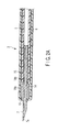
FIG. 2A is a longitudinal cross-sectional view of a main part, showing a state in which the needle is projected from the distal end of the outer tube of the endoscopic injector according to the first embodiment; -
FIG. 2B is a longitudinal cross-sectional view of a main part, showing a state in which the needle is retreated in the outer tube of the endoscopic injector according to the first embodiment; -
FIG. 2C is a longitudinal cross-sectional view of a main part, showing a state of an operation section in a case where the needle is retreated in the outer tube of the endoscopic injector according to the first embodiment; and -
FIG. 3 is a side view showing an example of an endoscope in which the endoscopic injector according to the first embodiment is inserted. - A first embodiment of the present invention will now be described with reference to the accompanying drawings.
FIG. 1A andFIG. 1B show anendoscopic injector 1 according to the present embodiment. Theendoscopic injector 1 includes anelongated insertion section 3 which is inserted in a channel of an endoscope 2 (seeFIG. 3 ) and is inserted into the body through the channel, and anoperation section 4 which is coupled to a proximal end portion of theinsertion section 3. - As shown in
FIG. 2A andFIG. 2B , theinsertion section 3 includes a double tube which comprises anouter tube 5 and aninner tube 6 that is advancible/retreatable in theouter tube 5. Further, a pipe-shapedneedle body 7 is attached to a distal end of theinner tube 6. Apointed puncture portion 7a, which is obliquely cut at an angle of, e.g. 30°, is formed at a needle tip of theneedle body 7. - At least the
inner tube 6 andouter tube 5 are formed of different kinds of plastic materials, and theouter tube 5 is formed of a material with a higher rigidity than a material of theinner tube 6. In the present embodiment, it is preferable that theouter tube 5 be formed of a plastic material with a higher bending elasticity modulus than a material of theinner tube 6. Further, it is preferable that theouter tube 5 andinner tube 6 be formed of different polyolefin plastics. For example, it is preferable that theouter tube 5 be formed of polypropylene (PP), and theinner tube 6 be formed of low-density polyethylene (LDPE). - Furthermore, in the present embodiment, the
outer tube 5 has an inside diameter of φ1.8 mm and an outside diameter of φ2.3 mm. Theinner tube 6 has an inside diameter of φ0.7 mm and an outside diameter of φ1.5 mm. Theneedle body 7 is formed of stainless steel material (SUS304). - The
operation section 4 is composed of anoperation section body 8 which is fixed to a proximal end portion of theouter tube 5, and amouthpiece unit 10 which is attached to a proximal end of theinner tube 6 via a stainless-steel pipe 9. As shown inFIG. 2C , the stainless-steel pipe 9 is fixed to a distal end portion of themouthpiece unit 10 by insert molding. Amouthpiece 11 is formed at a proximal end of themouthpiece unit 10. - Further, in the
operation section 4, theoperation section body 8 andmouthpiece unit 10 are advancible/retreatable. As shown inFIG. 1A , if themouthpiece unit 10 is pushed relative to theoperation section body 8, theneedle body 7 projects from a distal end opening 13 of theouter tube 5, as shown inFIG. 2A . If themouthpiece unit 10 is pulled to the proximal side, relative to theoperation section body 8, as shown inFIG. 1B andFIG. 2C , theneedle body 7 is accommodated in theouter tube 5, as shown inFIG. 2B . - At a distal end portion of the
outer tube 5, an engagingabutment portion 12, which is formed of an edge portion projecting radially inward of theouter tube 5, is formed integral with theouter tube 5 in a collar shape by thermal molding. Since theengaging abutment portion 12 is formed in a collar shape, the distal end opening 13 of theouter tube 5, which is formed at the center of theengaging abutment portion 12, is smaller than the inside diameter of theouter tube 5, and thedistal end opening 13 is larger than the outside diameter of theneedle body 7. - A stepped cylindrical engaging
member 14 having a large-diameter portion 14a and a small-diameter portion 14b is fixed on the outer periphery of theneedle body 7 by means of so-called caulking (caulking by tightening in plural (2 to 4) directions). - In this case, the outside diameter of the large-
diameter portion 14a is less than the inside diameter of theouter tube 5 and is greater than the diameter of thedistal end opening 13. Thereby, restriction means is constituted. When theinner tube 6 is pushed relative to theouter tube 5 in the operation of pushing themouthpiece unit 10 into theoperation section body 8 by theoperation section 4 and the distal end portion of theneedle body 7 is projected from the distal end opening 13 of theouter tube 5, the distal end face of the engagingmember 14 abuts on the inner end face of theengaging abutment portion 12 of theouter tube 5. Thus, further advancement is restricted by the restriction means. - The inside diameter of the small-
diameter portion 14b of the engagingmember 14 is substantially equal to the inside diameter of theinner tube 6. A distal end portion of theinner tube 6 is tightly fitted on the outer periphery of the small-diameter portion 14b. This fitting coupling part is fixed by an adhesive 15. The engagingmember 14 is a member which fills a clearance between the outside diameter (outer periphery) of theneedle body 7 and the inside diameter (inner periphery) of theinner tube 6. Theinner tube 6 and theneedle body 7 are coupled via the engagingmember 14. - The adhesive 15 is coated so as to also cover a part of the outer peripheral surface of the
needle body 7, beyond the proximal end face of the engagingmember 14. Thereby, theinner tube 6 and engagingmember 14 are bonded and at the same time water-tightness between theneedle body 7 and engagingmember 14 is ensured. -
FIG. 3 shows an example of anendoscope 2 in which theendoscopic injector 1 according to the first embodiment is inserted. Theendoscope 2 includes anelongated insertion section 16 which is inserted into the body, and anoperation section 17 which is coupled to a proximal end portion of theinsertion section 16. Theinsertion section 16 includes an elongatedflexible tube section 18, abending section 19 having a proximal end portion coupled to the distal end of theflexible tube section 18, and a distal-endrigid section 20 having a proximal end portion coupled to the distal end of thebending section 19. A distal end face of the distal-endrigid section 20 is provided with an illumination optical system, an observation optical system, a distal end opening portion of a therapeutic device insertion channel and an air-feed/water-feed nozzle, which are all not shown. The bendingsection 19 is configured to be bendable from a normal straight state as indicated by a dot-and-dash line inFIG. 3 to a bent state as indicated by a solid line or a two-dot-and-dash line inFIG. 3 . - The
operation section 17 is coupled to a proximal end portion of theflexible tube section 18. Theoperation section 17 is provided with a graspingsection 21 which is grasped by a surgeon. A proximal end portion of auniversal cord 22 is coupled to the graspingsection 21. Aconnector section 23, which is connected to a light source device, a video processor, etc., which are not shown, is coupled to a distal end portion of theuniversal cord 22. - Further, the grasping
section 21 is provided with an up-and-downbending operation knob 24 and a right-and-leftbending operation knob 25 for bend-operating thebending section 19, asuction button 26, an air-feed/water-feed button 27,various switches 28 for endoscopic photography, and a therapeuticdevice insertion section 29. The therapeuticdevice insertion section 29 is provided with a therapeuticdevice insertion hole 30 communicating with a proximal end portion of the therapeutic device insertion channel that is provided in theinsertion section 16. - The
insertion section 3 of theendoscopic injector 1 is inserted into the therapeutic device insertion channel from the therapeuticdevice insertion hole 30 of theendoscope 2, and is pushed to the distal-endrigid section 20, and then theinsertion section 3 is projected outward from the distal end opening portion of the therapeutic device insertion channel. - When the
endoscopic injector 1 of the present embodiment is used, themouthpiece unit 10 is pulled to the movement limit position on the proximal side, relative to theoperation section body 8, and theneedle body 7 is set in the state in which theneedle body 7 is accommodated in the outer tube 5 (the state shown inFIGS. 1B ,2B and2C . In this state, theinsertion section 3 of theendoscopic injector 1 is inserted in the therapeutic device insertion channel of theendoscope 2 that is inserted in the body cavity in advance. Then, the distal end portion of theouter tube 5 of theinsertion section 3 is projected into the body cavity from the distal end of the endoscope. - Subsequently, the
mouthpiece unit 10 is pushed relative to theoperation section body 8, and theneedle body 7 is fixed in the state in which theneedle body 7 projects from the distal end of the outer tube 5 (the state shown inFIG. 1A andFIG. 2A ). In this projecting state, themouthpiece unit 10 is pushed in by holding theoperation section body 8 at the proximal part of theouter tube 5 of theendoscopic injector 1, which is out of the proximal end portion of the therapeutic device insertion channel of theendoscope 2. Thereby, theneedle body 7 is made to pierce a target tissue, and a medicine, for instance, is fed by a syringe, which is attached to themouthpiece 11 in advance, and is injected into the tissue to perform medical treatment. - Next, the operation of the above-described structure is described. When the
endoscopic injector 1 of the present embodiment is used, theinsertion section 3 of theendoscopic injector 1 is inserted into the body through the therapeutic device insertion channel of theendoscope 2. At this time, theendoscopic injector 1 is operated in the state in which theinsertion section 3 of theendoscopic injector 1 is bent in accordance with the shape of theinsertion section 16 of theendoscope 2. The sliding resistance at the time when theinner tube 6 andouter tube 5 are advanced/retreated in the bent state occurs because theouter tube 5 is collapsed and pushed on theinner tube 6 when theinner tube 6 andouter tube 5 are bent. Further, in the case where theinner tube 6 has a higher rigidity than theouter tube 5, the frictional resistance increases due to the phenomenon that theinner tube 6 is strongly rubbed on the inner side of theouter tube 5 which is bent at the time of the operation of projecting theneedle body 7 by advancing theinner tube 6 relative to theouter tube 5. - In addition, in the case where the material of the
inner tube 6 is the same as the material of theouter tube 5, the outer peripheral surface of theinner tube 6 and the inner peripheral surface of theouter tube 5, which are put in sliding contact with each other, have mutually close atomic bond states, and these surfaces have high affinity. As a result, the frictional resistance increases. Besides, the frictional resistance is greatly influenced by the characteristics of the surfaces that are put in sliding contact.
Hence, as regards the hardness of the double tube of theinsertion section 3 of theendoscopic injector 1, the hardness of theinner tube 6 is set to be lower than that of theouter tube 5, and the materials of at least the sliding surfaces of theouter tube 5 andinner tube 6 are made different. Thereby, the frictional resistance at the time of bending can be decreased. The hardness of theouter tube 5 andinner tube 6, which has been described above, greatly affects the frictional resistance at the time of bending of the double tube comprising theouter tube 5 andinner tube 6, and thus a bending elasticity modulus may be substituted for the characteristic of the material. - The measurement of the operation force amount of the double tube for the therapeutic device, which is assembled in the
insertion section 3 of theendoscopic injector 1 according to the present embodiment, was conducted as follows. When the operation force amount of the double tube is measured, theinner tube 6 is advanced/retreated in theouter tube 5 in the state in which theinsertion section 3 of theendoscopic injector 1 is inserted in the therapeutic device insertion channel of theendoscope 2. In this case, theendoscope 2 is held in a bent state in which theflexible tube section 18 of theinsertion section 16 is wound by a single loop with a proper diameter (e.g. a radius R of 50 mm). - Then, the
insertion section 3 of theendoscopic injector 1 is inserted in the therapeutic device insertion channel from the therapeuticdevice insertion hole 30 of theendoscope 2 and is operated and pushed to the distal-endrigid section 20, and theinsertion section 3 is set in the state in which theinsertion section 3 projects from the distal end opening of the therapeutic device insertion channel. In this state, the work for measuring the operation force amount of the double tube for the therapeutic device of theinsertion section 3 of theendoscopic injector 1 is conducted. Thereby, in the state in which theinsertion section 3 of theendoscopic injector 1 is bent and wound by a single loop along the shape of the therapeutic device insertion channel of theendoscope 2, the force amount of sliding is measured with the amount of projection of theneedle body 7 being set at, e.g. 30 mm. - Table 1 shows a measurement result of the operation force amount (N) of the double tube for the therapeutic device of the
insertion section 3 of theendoscopic injector 1 in the case where the combination of the plastic material of theinner tube 6 and the plastic material of theouter tube 5 of the double tube for the therapeutic device of theinsertion section 3 of theendoscopic injector 1 is varied.Table 1 No. of experiment Outer tube Inner tube Operation force amount (N) 1 PP PP 7.15 2 HDPE HDPE 10 or more 3 PTFE PTFE 5.62 4 HDPE PP 4.94 5 PP LDPE 0.25 6 PP LLDPE 0.80 7 PP PFA 0.24 - The data of the double tube for the therapeutic device, which was used in the measurement experiment of the operation force amount (N) of the double tube for the therapeutic device, is as follows:
- Inner tube 6: the outside diameter is φ1.5 mm and the inside diameter is φ0.7 mm.
- Outer tube 5: the outside diameter is φ2.3 mm and the inside diameter is φ1.8 mm.
- Table 2 shows the characteristics of the materials which were used in the measurement of the operation force amount (N) of the double tube for the therapeutic device.
Table 2 Material Bending elasticity modulus Hardness PP 1500 MPa R100 PTFE 550 MPa D55 HDPE 1050 MPa D67 LDPE 130 MPa D49 LLDPE 330 MPa D53 - In Table 2, R is Rockwell hardness, and D is Shore hardness. Of the materials, HDPE is a high-density polyethylene, and LLDPE is linear low-density polyethylene. It is preferable that any of the materials in Table 2 be transparent or semitransparent, so that the presence/absence of bubbles and the condition of passage of liquid medicine can be confirmed when liquid medicine, or the like, is passed through the double tube.
- As indicated in the measurement experiment result in Table 2 of the operation force amount (N) of the double tube for the therapeutic device, in the case where the
outer tube 5 andinner tube 6 are formed of the same material as in the cases of experiment Nos. 1 to 3, the operation force amount (N) is relatively high, namely, 7.15, 10 or more, and 5.62. In the case where the hardness of theouter tube 5 is lower than that of theinner tube 6, as in the case of experiment No. 4, the operation force amount (N) is 4.94 and is also high. - By contrast, in the case where the present invention is applied (i.e. the hardness of the
inner tube 6 is lower than that of the outer tube 5) as in the cases of experiment Nos. 5 and 6, the operation force amount (N) is relatively low, namely, 0.25 and 0.80. It is thus confirmed that the operation force amount is smaller in the case where the hardness of theinner tube 6 is lower than that of the outer tube 5 (experiment Nos. 5 and 6) than in the case where theinner tube 6 andouter tube 5 are formed of the same material (experiment Nos. 1 to 3) or in the case where the hardness of theouter tube 5 is lower than that of the inner tube 6 (experiment No. 4). - As is clear from the measurement result of Table 1, the operation force amount (N) can be decreased in the case where the hardness of the
inner tube 6 is lower than that of theouter tube 5. As regards the combination of theouter tube 5 of PP and theinner tube 6 of LLDPE as in the case of experiment No. 6, in the case where the thickness of theinner tube 6 was reduced such that the outside diameter was set at φ1.5 mm and the inside diameter was set at φ0.9 mm, the operation force amount (N) decreased to 0.55. - The following advantageous effects are obtained with the above-described structure. Specifically, in the
endoscopic injector 1 according to the present embodiment, at least theinner tube 6 andouter tube 5 are formed of different kinds of plastic materials, and theouter tube 5 is formed of a material with a higher rigidity than a material of theinner tube 6. Thus, when theoperation section 4 is operated and the operation of projecting theneedle body 7 is performed by advancing theinner tube 6 relative to theouter tube 5 in the state in which theinsertion section 3 of theendoscopic injector 1 is bent, the magnitude of the sliding frictional resistance between theinner tube 6 and theouter tube 5 can be reduced. Therefore, even in the case where medical treatment by theendoscopic injector 1 is performed in the state in which theinsertion section 3 that is inserted in the body is bent, the operability of the operation of projecting theneedle body 7 of theendoscopic injector 1 from the distal end opening 13 of theouter tube 5 is good, and a stable operation can be performed for a diseased part. - In addition, as in the case of experiment No. 7, even if the material of the
inner tube 6 is replaced with PFA, the operation force amount that is substantially equal to the case of using LDPE is indicated. Thus, the same effect can be obtained even in the case of using fluoroplastics. - In the
endoscopic injector 1 using the double tube comprising theinner tube 6 andouter tube 5, if the hardness and material are varied, the linear thermal expansion coefficient varies accordingly. Thus, such a phenomenon may possibly occur that theneedle body 7 projects from the distal end opening 13 of theouter tube 5 due to thermal variation (thermal expansion) even at times when there is no need. In addition, when theneedle body 7 projects from the distal end opening 13 of theouter tube 5 at a time when necessary, theneedle body 7 may not smoothly project. - Normally, the temperature of the environment of use of the
endoscopic injector 1 is about 36°C since theendoscopic injector 1 is used in the body. On the other hand, the temperature of the environment of the therapeutic treatment room is, in general, about 25 to 28°C. Thus, the difference between the temperature of the environment of the therapeutic treatment room and the temperature of the environment of use in the body is about 10°C. In the present embodiment, the linear thermal expansion coefficient is so set as to prevent occurrence of problems in projection/retreat of theneedle body 7 due to linear thermal expansion or contraction at these temperatures. Specifically, the difference between the linear thermal expansion coefficient of the material of theinner tube 6 and the linear thermal expansion coefficient of the material of theouter tube 5 is set at 5X 10⁻⁵/°C or less. Thereby, it becomes possible to prevent such a phenomenon that theneedle body 7 projects from the distal end opening 13 of theouter tube 5 due to thermal variation (thermal expansion), or such a phenomenon that the projection of theneedle body 7 becomes unsmooth when theneedle body 7 is projected, where necessary, from the distal end opening 13 of theouter tube 5. - Furthermore, if the length of the therapeutic device insertion channel of the
endoscope 2 is large, if there is a difference between the linear thermal expansion coefficient of the material of theinner tube 6 and the linear thermal expansion coefficient of the material of theouter tube 5, there is a possibility that necessary treatment cannot be performed, for example, because theneedle body 7 may not reach a diseased part when theneedle body 7 is projected from the distal end opening 13 of theouter tube 5. It is thus preferable that the linear thermal expansion coefficient of the material of each of theinner tube 6 andouter tube 5 be set at 20X 10-5/°C or less. - The present invention is not limited to the above-described embodiment and, needless to say, the invention may variously be modified in practice without departing from the spirit of the invention.
- The present invention is effective in a technical field of using an endoscopic therapeutic device such as an endoscopic injector, and a double tube for a therapeutic device, and in a technical field of manufacturing the endoscopic therapeutic device such as an endoscopic injector, and the double tube for a therapeutic device.
Claims (14)
- An endoscopic therapeutic device comprising:an insertion section which is inserted in a channel of an endoscope, the insertion section including a double tube having an outer tube and an inner tube which is advancibly/retreatably inserted in the outer tube; andan operation section which is coupled to a proximal end portion of the insertion section and performs an advancing/retreating operation of the inner and outer tubes,wherein the double tube is configured such that at least the inner tube and the outer tube are formed of different kinds of plastic materials, and the outer tube is formed of a material with a higher rigidity than a material of the inner tube.
- The endoscopic therapeutic device according to claim 1, wherein the outer tube has a higher bending elasticity modulus than the inner tube.
- The endoscopic therapeutic device according to claim 1, wherein the plastic materials are different kinds of polyolefin plastics, of which the outer tube and the inner tube are formed, respectively.
- The endoscopic therapeutic device according to claim 1, wherein the plastic materials are a polyolefin plastic and a fluoroplastic, of which the outer tube and the inner tube are formed, respectively.
- The endoscopic therapeutic device according to claim 1, wherein the outer tube is formed of polypropylene and the inner tube is formed of polyethylene.
- The endoscopic therapeutic device according to claim 1, wherein the outer tube is formed of polypropylene and the inner tube is formed of PFA.
- The endoscopic therapeutic device according to claim 1, wherein a hollow needle body is attached to a distal end of the inner tube, and the operation section includes a needle body operation section which projects the needle body at the distal end of the inner tube to an outside from a distal end portion of the outer tube, and which retreats the needle body.
- The endoscopic therapeutic device according to claim 1, wherein each of a linear thermal expansion coefficient of the outer tube and a linear thermal expansion coefficient of the inner tube is 20 X 10-5/°C or less, and a difference between the respective linear thermal expansion coefficients is 5 X 10⁻⁵/°C or less.
- A double tube for a therapeutic device, which includes an outer tube and an inner tube which is advancibly/retreatably inserted in the outer tube,
wherein the double tube is configured such that at least the inner tube and the outer tube are formed of different kinds of plastic materials, and the outer tube is formed of a material with a higher rigidity than a material of the inner tube. - The double tube for a therapeutic device, according to claim 9, wherein the outer tube has a higher bending elasticity modulus than the inner tube.
- The double tube for a therapeutic device, according to claim 9, wherein the plastic materials are different kinds of polyolefin plastics, of which the outer tube and the inner tube are formed, respectively.
- The double tube for a therapeutic device, according to claim 9, wherein the plastic materials are a polyolefin plastic and a fluoroplastic, of which the outer tube and the inner tube are formed, respectively.
- The double tube for a therapeutic device, according to claim 7, wherein the outer tube is formed of polypropylene and the inner tube is formed of polyethylene.
- The double tube for a therapeutic device, according to claim 7, wherein the outer tube is formed of polypropylene and the inner tube is formed of PFA.
Applications Claiming Priority (2)
| Application Number | Priority Date | Filing Date | Title |
|---|---|---|---|
| JP2005303202 | 2005-10-18 | ||
| PCT/JP2006/320781 WO2007046444A1 (en) | 2005-10-18 | 2006-10-18 | Treatment device for endoscope and double tube for the treatment device |
Publications (2)
| Publication Number | Publication Date |
|---|---|
| EP1949924A1 true EP1949924A1 (en) | 2008-07-30 |
| EP1949924A4 EP1949924A4 (en) | 2014-04-23 |
Family
ID=37962537
Family Applications (1)
| Application Number | Title | Priority Date | Filing Date |
|---|---|---|---|
| EP06811974.2A Withdrawn EP1949924A4 (en) | 2005-10-18 | 2006-10-18 | Treatment device for endoscope and double tube for the treatment device |
Country Status (6)
| Country | Link |
|---|---|
| US (1) | US8428710B2 (en) |
| EP (1) | EP1949924A4 (en) |
| JP (1) | JP5042029B2 (en) |
| KR (1) | KR101287769B1 (en) |
| CN (1) | CN101267851A (en) |
| WO (1) | WO2007046444A1 (en) |
Cited By (1)
| Publication number | Priority date | Publication date | Assignee | Title |
|---|---|---|---|---|
| TWI714279B (en) * | 2019-09-24 | 2020-12-21 | 丁原傑 | Temperature compensation current limiting device and elastic infusion system |
Families Citing this family (22)
| Publication number | Priority date | Publication date | Assignee | Title |
|---|---|---|---|---|
| JP2006500115A (en) | 2000-11-16 | 2006-01-05 | マイクロスフエリツクス・エル・エル・シー | Flexible and / or elastic seeds or strands for brachytherapy |
| US8187159B2 (en) | 2005-07-22 | 2012-05-29 | Biocompatibles, UK | Therapeutic member including a rail used in brachytherapy and other radiation therapy |
| US7736293B2 (en) | 2005-07-22 | 2010-06-15 | Biocompatibles Uk Limited | Implants for use in brachytherapy and other radiation therapy that resist migration and rotation |
| JP5011137B2 (en) * | 2008-01-22 | 2012-08-29 | 富士フイルム株式会社 | Endoscope injection needle and inner tube with a needle fixed to the tip |
| US9101735B2 (en) * | 2008-07-07 | 2015-08-11 | Intuitive Surgical Operations, Inc. | Catheter control systems |
| WO2010074153A1 (en) * | 2008-12-24 | 2010-07-01 | オリンパスメディカルシステムズ株式会社 | Treatment instrument |
| JP5372791B2 (en) * | 2010-01-20 | 2013-12-18 | オリンパス株式会社 | Insertion needle and catheter set |
| CN102551846B (en) * | 2012-01-18 | 2014-02-12 | 南京微创医学科技有限公司 | Disposable remote-injection syringe for use under endoscope |
| JP5885887B2 (en) * | 2014-01-29 | 2016-03-16 | オリンパス株式会社 | Rigid endoscope and treatment tool for prostate biopsy |
| JP6402465B2 (en) * | 2014-03-28 | 2018-10-10 | 住友ベークライト株式会社 | Endoscope injection needle and method for manufacturing endoscope injection needle |
| JP6311479B2 (en) * | 2014-06-20 | 2018-04-18 | 住友ベークライト株式会社 | Endoscope injection needle and method for manufacturing endoscope injection needle |
| CN109152879A (en) * | 2016-05-17 | 2019-01-04 | 奥林巴斯株式会社 | Endoscope-use injection needle |
| DK3474760T3 (en) | 2016-06-27 | 2023-03-20 | Galvanize Therapeutics Inc | Generator and a catheter with an electrode for treating a lung passage |
| JP2018102631A (en) * | 2016-12-27 | 2018-07-05 | レイクR&D株式会社 | Endoscopic syringe |
| EP3653103B1 (en) * | 2017-12-29 | 2023-11-15 | Menfis Korea Co., Ltd. | Surgical instrument for endoscope |
| JP7082928B2 (en) * | 2018-08-29 | 2022-06-09 | 宇部エクシモ株式会社 | Laminated tube |
| US12096915B2 (en) * | 2019-03-11 | 2024-09-24 | Gyrus Acmi, Inc. | Sheath location indicator and overextension preventer |
| CA3132792A1 (en) | 2019-05-15 | 2020-11-19 | Boston Scientific Scimed, Inc. | Medical device having asymmetric bending |
| CN115348844A (en) | 2020-04-08 | 2022-11-15 | 盖能适治疗股份有限公司 | Pulsed electric field waveform operation and use |
| DE102020122654A1 (en) * | 2020-08-31 | 2022-03-03 | Gaplast Gmbh | implant syringe |
| KR102583121B1 (en) * | 2020-12-17 | 2023-10-04 | 주식회사 오렌지메딕스 | Safety needle assembly for surgery |
| WO2023120255A1 (en) * | 2021-12-24 | 2023-06-29 | 富士フイルム株式会社 | Oversheath, endoscopic treatment tool device, and endoscopic instrument |
Family Cites Families (16)
| Publication number | Priority date | Publication date | Assignee | Title |
|---|---|---|---|---|
| AU9143982A (en) * | 1982-01-20 | 1983-07-28 | Sorenson Research Co. Inc. | Translating and positioning a catheter |
| JP3607173B2 (en) * | 1993-08-04 | 2005-01-05 | 株式会社足立ライト工業所 | Ball draining device for ball tray in pachinko machine |
| JP3614943B2 (en) * | 1994-09-29 | 2005-01-26 | オリンパス株式会社 | Endoscopic puncture needle |
| JPH08336591A (en) | 1995-06-13 | 1996-12-24 | Asahi Optical Co Ltd | Endoscope injection tool |
| US5964740A (en) * | 1996-07-09 | 1999-10-12 | Asahi Kogaku Kogyo Kabushiki Kaisha | Treatment accessory for an endoscope |
| JPH0938202A (en) * | 1995-08-04 | 1997-02-10 | Asahi Optical Co Ltd | Endoscope injection tool |
| JP3574530B2 (en) * | 1996-05-13 | 2004-10-06 | ペンタックス株式会社 | Endoscope treatment tool guide |
| US5882293A (en) * | 1996-09-05 | 1999-03-16 | Asahi Kogaku Kogyo Kabushiki Kaisha | Treatment accessories for endoscope |
| US5899850A (en) * | 1997-04-03 | 1999-05-04 | Asahi Kogaku Kogyo Kabushiki Kaisha | Treatment accessories for an endoscope |
| US6511462B1 (en) * | 1999-07-16 | 2003-01-28 | Terumo Kabushiki Kaisha | Catheter and method of manufacturing the same |
| JP4493126B2 (en) * | 1999-08-20 | 2010-06-30 | オリンパス株式会社 | Endoscopic needle |
| US6743206B1 (en) * | 2000-03-07 | 2004-06-01 | Syntheon, Llc | Endoscopic needle |
| US20020087076A1 (en) * | 2000-11-14 | 2002-07-04 | C-I-Medic Co., Ltd. | Catheter assemble |
| US6758806B2 (en) * | 2001-01-12 | 2004-07-06 | Napoli, Llc | Endoscopic devices and method of use |
| WO2003009884A2 (en) * | 2001-07-24 | 2003-02-06 | Artes Medical Usa, Inc. | Elongated syringe |
| JP2004290367A (en) * | 2003-03-26 | 2004-10-21 | Sumitomo Bakelite Co Ltd | Injection needle for endoscope |
-
2006
- 2006-10-18 CN CNA2006800342869A patent/CN101267851A/en active Pending
- 2006-10-18 JP JP2007541024A patent/JP5042029B2/en not_active Expired - Fee Related
- 2006-10-18 EP EP06811974.2A patent/EP1949924A4/en not_active Withdrawn
- 2006-10-18 KR KR1020087006415A patent/KR101287769B1/en not_active Expired - Fee Related
- 2006-10-18 WO PCT/JP2006/320781 patent/WO2007046444A1/en not_active Ceased
-
2008
- 2008-04-16 US US12/104,024 patent/US8428710B2/en active Active
Cited By (1)
| Publication number | Priority date | Publication date | Assignee | Title |
|---|---|---|---|---|
| TWI714279B (en) * | 2019-09-24 | 2020-12-21 | 丁原傑 | Temperature compensation current limiting device and elastic infusion system |
Also Published As
| Publication number | Publication date |
|---|---|
| KR20080057239A (en) | 2008-06-24 |
| CN101267851A (en) | 2008-09-17 |
| US20080208127A1 (en) | 2008-08-28 |
| JP5042029B2 (en) | 2012-10-03 |
| JPWO2007046444A1 (en) | 2009-04-23 |
| KR101287769B1 (en) | 2013-07-19 |
| US8428710B2 (en) | 2013-04-23 |
| WO2007046444A1 (en) | 2007-04-26 |
| EP1949924A4 (en) | 2014-04-23 |
Similar Documents
| Publication | Publication Date | Title |
|---|---|---|
| US8428710B2 (en) | Endoscopic therapeutic device and double tube for therapeutic device | |
| US7641638B2 (en) | Flexible elongate surgical needle device having a tissue engaging section being of greater flexibility than an intermediate section, and methods of using the device | |
| CN111248947B (en) | Adjustable curved biopsy needle and biopsy system | |
| US6258064B1 (en) | Helically advanceable endoscopic needle device | |
| US10076316B2 (en) | Needle biopsy device | |
| US6679873B2 (en) | Method for using a steerable catheter device | |
| JP6180575B2 (en) | Ultrasound puncture needle | |
| US6976955B2 (en) | Handle for medical devices, and medical device assemblies including a handle | |
| US6743206B1 (en) | Endoscopic needle | |
| JP5797361B1 (en) | Endoscopic treatment tool | |
| US20120238815A1 (en) | Insertion aid for endoscope | |
| WO2014125707A1 (en) | Biopsy system | |
| JP2015062532A (en) | Medical long member and connecting member | |
| JPH0984878A (en) | Catheter tube | |
| JP3231080B2 (en) | Catheter tube | |
| KR101873001B1 (en) | Endoscopic Treatment Instrument | |
| JP2005058431A (en) | Puncturing needle | |
| JPH0938202A (en) | Endoscope injection tool | |
| WO2016042849A1 (en) | Biopsy system | |
| JP2011104158A (en) | Injection needle for endoscope | |
| JP2015062533A (en) | Medical longitudinal member | |
| WO2006067917A1 (en) | Puncture needle of endoscope | |
| WO2014045677A1 (en) | Biopsy needle and biopsy system | |
| JP3098062B2 (en) | Catheter tube | |
| JP2005329078A (en) | Puncture needle device for endoscope |
Legal Events
| Date | Code | Title | Description |
|---|---|---|---|
| PUAI | Public reference made under article 153(3) epc to a published international application that has entered the european phase |
Free format text: ORIGINAL CODE: 0009012 |
|
| 17P | Request for examination filed |
Effective date: 20080417 |
|
| AK | Designated contracting states |
Kind code of ref document: A1 Designated state(s): DE FR GB |
|
| DAX | Request for extension of the european patent (deleted) | ||
| RBV | Designated contracting states (corrected) |
Designated state(s): DE FR GB |
|
| A4 | Supplementary search report drawn up and despatched |
Effective date: 20140326 |
|
| RIC1 | Information provided on ipc code assigned before grant |
Ipc: A61B 1/00 20060101ALI20140314BHEP Ipc: A61B 17/34 20060101ALI20140314BHEP Ipc: A61M 5/14 20060101AFI20140314BHEP |
|
| 17Q | First examination report despatched |
Effective date: 20150116 |
|
| STAA | Information on the status of an ep patent application or granted ep patent |
Free format text: STATUS: THE APPLICATION IS DEEMED TO BE WITHDRAWN |
|
| 18D | Application deemed to be withdrawn |
Effective date: 20151203 |