EP1949199B1 - Apparatus and method for dispensing materials volumetrically and gravimetrically based on a stored formula - Google Patents
Apparatus and method for dispensing materials volumetrically and gravimetrically based on a stored formula Download PDFInfo
- Publication number
- EP1949199B1 EP1949199B1 EP06814509.3A EP06814509A EP1949199B1 EP 1949199 B1 EP1949199 B1 EP 1949199B1 EP 06814509 A EP06814509 A EP 06814509A EP 1949199 B1 EP1949199 B1 EP 1949199B1
- Authority
- EP
- European Patent Office
- Prior art keywords
- amount
- pump
- dispense
- half amount
- ingredients
- Prior art date
- Legal status (The legal status is an assumption and is not a legal conclusion. Google has not performed a legal analysis and makes no representation as to the accuracy of the status listed.)
- Not-in-force
Links
- 238000000034 method Methods 0.000 title claims description 59
- 239000000463 material Substances 0.000 title description 23
- 239000004615 ingredient Substances 0.000 claims description 60
- 230000033001 locomotion Effects 0.000 claims description 41
- 230000009969 flowable effect Effects 0.000 claims description 10
- 230000009021 linear effect Effects 0.000 claims description 10
- 238000005303 weighing Methods 0.000 claims description 10
- 238000004891 communication Methods 0.000 claims description 3
- 239000012190 activator Substances 0.000 claims description 2
- 239000000843 powder Substances 0.000 description 51
- 239000007788 liquid Substances 0.000 description 17
- 239000012530 fluid Substances 0.000 description 16
- 239000003973 paint Substances 0.000 description 14
- 230000008569 process Effects 0.000 description 13
- 239000003086 colorant Substances 0.000 description 10
- 239000002537 cosmetic Substances 0.000 description 10
- 239000000118 hair dye Substances 0.000 description 9
- 238000013459 approach Methods 0.000 description 8
- 230000009471 action Effects 0.000 description 6
- 239000000203 mixture Substances 0.000 description 6
- -1 conditioners Substances 0.000 description 5
- 238000009472 formulation Methods 0.000 description 5
- 238000005259 measurement Methods 0.000 description 4
- 230000008901 benefit Effects 0.000 description 3
- 238000004364 calculation method Methods 0.000 description 3
- 238000012937 correction Methods 0.000 description 3
- 230000000694 effects Effects 0.000 description 3
- 238000009413 insulation Methods 0.000 description 3
- 230000007774 longterm Effects 0.000 description 3
- 229910052751 metal Inorganic materials 0.000 description 3
- 239000002184 metal Substances 0.000 description 3
- MHAJPDPJQMAIIY-UHFFFAOYSA-N Hydrogen peroxide Chemical compound OO MHAJPDPJQMAIIY-UHFFFAOYSA-N 0.000 description 2
- 239000004743 Polypropylene Substances 0.000 description 2
- QVGXLLKOCUKJST-UHFFFAOYSA-N atomic oxygen Chemical compound [O] QVGXLLKOCUKJST-UHFFFAOYSA-N 0.000 description 2
- 230000001419 dependent effect Effects 0.000 description 2
- 238000013461 design Methods 0.000 description 2
- 238000009826 distribution Methods 0.000 description 2
- 230000006870 function Effects 0.000 description 2
- 238000004519 manufacturing process Methods 0.000 description 2
- 230000007246 mechanism Effects 0.000 description 2
- 238000002156 mixing Methods 0.000 description 2
- 239000001301 oxygen Substances 0.000 description 2
- 229910052760 oxygen Inorganic materials 0.000 description 2
- 229920001155 polypropylene Polymers 0.000 description 2
- 229920001343 polytetrafluoroethylene Polymers 0.000 description 2
- 239000004810 polytetrafluoroethylene Substances 0.000 description 2
- 230000009467 reduction Effects 0.000 description 2
- 239000000523 sample Substances 0.000 description 2
- 239000002453 shampoo Substances 0.000 description 2
- FECNOIODIVNEKI-UHFFFAOYSA-N 2-[(2-aminobenzoyl)amino]benzoic acid Chemical class NC1=CC=CC=C1C(=O)NC1=CC=CC=C1C(O)=O FECNOIODIVNEKI-UHFFFAOYSA-N 0.000 description 1
- 206010039792 Seborrhoea Diseases 0.000 description 1
- 238000003324 Six Sigma (6σ) Methods 0.000 description 1
- 229910052782 aluminium Inorganic materials 0.000 description 1
- XAGFODPZIPBFFR-UHFFFAOYSA-N aluminium Chemical compound [Al] XAGFODPZIPBFFR-UHFFFAOYSA-N 0.000 description 1
- 238000004458 analytical method Methods 0.000 description 1
- 238000005452 bending Methods 0.000 description 1
- 238000006243 chemical reaction Methods 0.000 description 1
- 238000004040 coloring Methods 0.000 description 1
- 238000005056 compaction Methods 0.000 description 1
- 238000013329 compounding Methods 0.000 description 1
- 238000006073 displacement reaction Methods 0.000 description 1
- 239000003814 drug Substances 0.000 description 1
- 230000037336 dry skin Effects 0.000 description 1
- 239000000975 dye Substances 0.000 description 1
- 238000005516 engineering process Methods 0.000 description 1
- 238000001125 extrusion Methods 0.000 description 1
- 239000000945 filler Substances 0.000 description 1
- 239000008187 granular material Substances 0.000 description 1
- 239000011440 grout Substances 0.000 description 1
- 239000012774 insulation material Substances 0.000 description 1
- 239000003607 modifier Substances 0.000 description 1
- 230000009022 nonlinear effect Effects 0.000 description 1
- 230000037311 normal skin Effects 0.000 description 1
- 230000037312 oily skin Effects 0.000 description 1
- 239000007800 oxidant agent Substances 0.000 description 1
- 239000002245 particle Substances 0.000 description 1
- 239000008188 pellet Substances 0.000 description 1
- 239000000049 pigment Substances 0.000 description 1
- 239000004014 plasticizer Substances 0.000 description 1
- 229920000642 polymer Polymers 0.000 description 1
- 230000008439 repair process Effects 0.000 description 1
- 239000011347 resin Substances 0.000 description 1
- 229920005989 resin Polymers 0.000 description 1
- 230000002441 reversible effect Effects 0.000 description 1
- 238000007789 sealing Methods 0.000 description 1
- 239000002904 solvent Substances 0.000 description 1
- 238000001228 spectrum Methods 0.000 description 1
- 230000003068 static effect Effects 0.000 description 1
- 230000003813 thin hair Effects 0.000 description 1
- 238000009423 ventilation Methods 0.000 description 1
- 238000012795 verification Methods 0.000 description 1
- XLYOFNOQVPJJNP-UHFFFAOYSA-N water Substances O XLYOFNOQVPJJNP-UHFFFAOYSA-N 0.000 description 1
Images




Classifications
-
- G—PHYSICS
- G05—CONTROLLING; REGULATING
- G05D—SYSTEMS FOR CONTROLLING OR REGULATING NON-ELECTRIC VARIABLES
- G05D11/00—Control of flow ratio
- G05D11/02—Controlling ratio of two or more flows of fluid or fluent material
- G05D11/13—Controlling ratio of two or more flows of fluid or fluent material characterised by the use of electric means
- G05D11/131—Controlling ratio of two or more flows of fluid or fluent material characterised by the use of electric means by measuring the values related to the quantity of the individual components
- G05D11/133—Controlling ratio of two or more flows of fluid or fluent material characterised by the use of electric means by measuring the values related to the quantity of the individual components with discontinuous action
- G05D11/134—Controlling ratio of two or more flows of fluid or fluent material characterised by the use of electric means by measuring the values related to the quantity of the individual components with discontinuous action by sensing the weight of the individual components
-
- B—PERFORMING OPERATIONS; TRANSPORTING
- B01—PHYSICAL OR CHEMICAL PROCESSES OR APPARATUS IN GENERAL
- B01F—MIXING, e.g. DISSOLVING, EMULSIFYING OR DISPERSING
- B01F33/00—Other mixers; Mixing plants; Combinations of mixers
- B01F33/80—Mixing plants; Combinations of mixers
- B01F33/84—Mixing plants with mixing receptacles receiving material dispensed from several component receptacles, e.g. paint tins
- B01F33/841—Mixing plants with mixing receptacles receiving material dispensed from several component receptacles, e.g. paint tins with component receptacles fixed in a circular configuration on a horizontal table, e.g. the table being able to be indexed about a vertical axis
-
- B—PERFORMING OPERATIONS; TRANSPORTING
- B01—PHYSICAL OR CHEMICAL PROCESSES OR APPARATUS IN GENERAL
- B01F—MIXING, e.g. DISSOLVING, EMULSIFYING OR DISPERSING
- B01F35/00—Accessories for mixers; Auxiliary operations or auxiliary devices; Parts or details of general application
- B01F35/80—Forming a predetermined ratio of the substances to be mixed
- B01F35/88—Forming a predetermined ratio of the substances to be mixed by feeding the materials batchwise
- B01F35/881—Forming a predetermined ratio of the substances to be mixed by feeding the materials batchwise by weighing, e.g. with automatic discharge
-
- B—PERFORMING OPERATIONS; TRANSPORTING
- B01—PHYSICAL OR CHEMICAL PROCESSES OR APPARATUS IN GENERAL
- B01F—MIXING, e.g. DISSOLVING, EMULSIFYING OR DISPERSING
- B01F2101/00—Mixing characterised by the nature of the mixed materials or by the application field
- B01F2101/30—Mixing paints or paint ingredients, e.g. pigments, dyes, colours, lacquers or enamel
Definitions
- Apparatuses and methods are disclosed for dispensing a plurality of formulas volumetrically and gravimetrically using a controller having a memory that stores a plurality of formulas.
- the controller is linked to a plurality of pumps or conveyors, with each pump connected to a container holding one of the materials to be dispensed according to one of the formulas.
- the controller is also linked to a scale for measuring the amount of liquid or powder dispensed by its respective pump.
- the disclosed apparatuses and methods are applicable to liquid and powder ingredients.
- Some currently available paint colorant dispensers utilize nutating pumps and a computer control system to control the nutating pumps.
- Nutating pumps have a piston which is positioned inside of a housing having a fluid inlet and a fluid outlet. The piston simultaneously slides axially and rotates inside the housing.
- the dispense stroke or cycle can be broken down into a number of discreet steps or segments for extremely accurate volumetric dispenses. For example, a minimum dispense can be as little as 1/256 of a fluid ounce as illustrated in U.S. Patent Nos. 6,749,402 , 6,540,486 and 6,398,515 , all commonly assigned with the present application.
- These patents all disclose improved nutating pump technologies that are applicable to paint colorant dispensing as well as the dispensing of hair dyes, other cosmetics applications and other fluids.
- volumetric dispensing is not as accurate as gravimetric dispensing as air bubbles or density variations can compromise the accuracy of the amounts dispensed.
- the machine includes a plurality of containers for storing various colorants or dye intermediates and developer solutions that typically contain an oxidizer (e.g. , hydrogen peroxide).
- an oxidizer e.g. , hydrogen peroxide
- US 2003/0121561 relates to an apparatus and a process for rapidly and accurately dispensing fluids, in which at least one component is dispensed into the reaction vessel in two or three stages. In this process, the amount of fluid dispensed in the second and third stages is determined on the basis of the mass flow rate calculated in the preceding sub-step.
- US 4961887 discloses an apparatus and process for manufacturing insulation for metallic rod which includes a mechanism for housing a plurality of ingredients, scales for weighing a predetermined quantity of each ingredient, a blender for blending predetermined amounts of each ingredient into one material, a mixer to mix the dry blend of ingredients, a mill to form the blended material into strips, a dicer to transform the strips into pellets of insulation, an extruder for placing insulation around the metallic rod, a conveyor to transport the ingredients and/or material between each of the above steps, a controller for outputting commands to the blender and receiving inputs from the scales to obtain the predetermined amount of each ingredient, and a computer for verifying that the correct amount of each ingredient has been obtained.
- the ingredients used in the manufacture of this insulation material include plasticizers, fillers, a resin, and modifiers.
- the controller employs multiple setpoints to gradually obtain the required ingredient weight through what is known as a dribble feed function.
- an improved dispensing methodology that provides for faster dispense times for multiple ingredient formulations where the ingredients may be liquid or powder or a combination of liquids and powders.
- values for the difference between the first half amount and the actual first half amount dispensed are inputted to the calibration table stored in a memory for use in future calculations relating to the motion of the pump.
- values for the difference between the second half amount and the actual second half amount dispensed are also inputted to the calibration table stored for use in future calculations relating to the motion of the pump.
- the initial amount for each ingredient ranges from about 70% to about 95% of the target amount for that ingredient.
- the less than the target amount is greater than 90% of the target amount.
- the additional amount i.e., the amount remaining to be dispensed after the initial amount is dispensed" is an amount that is less than two full strokes of a piston pump if the pump is a piston pump or two rotation so the screw feeder of the metering pump if the pump is a metering pump.
- each of the n ingredients is provided in its own reservoir that is in communication with its own pump and the pumps or conveyors are mounted on a rotary turntable.
- the selecting further comprises selecting the formula from a memory in which a plurality of formulas are stored. In a related refinement, the selecting further comprises selecting a total weight of the formula to be dispensed in addition to the selecting of the formula.
- any calculation of the motion of the pump for a particular ingredient may comprise using a calibration table or a table of stored values that are updated at least periodically and preferably at least once during each dispense to calculate the desired motion of the pump.
- a separate pump and a separate set of calibration values for each ingredient may be used.
- the motion of each pump is executed by a stepper motor under the control of a controller and the calculating of the motion of the pump comprises using the calibration table to calculate the number of steps for the stepper motor.
- each pump is a nutating pump as opposed to a conventional piston pump.
- selecting a total weight of the formula to be dispensed in addition to the selecting of the formula is selected.
- the reading of the scale and accounting for the weight of the receptacle comprises zeroing of the scale.
- a dispensing system is disclosed, according to claim 18.
- a plurality of flowable ingredients can be provided in individual containers and utilizing individually controlled dispense pumps that each draw one flowable ingredient from its individual container, the pumps being positionable to dispense into a common receptacle associated with a weighing device, the weighing device and pumps linked to a controller having a memory, the method comprising: operating a selected pump to move an initial assumed amount of one of the flowable ingredients that is less than a target amount for said ingredient into the container; weighing the container and determining an actual initial amount dispensed and subtracting that actual initial amount from the target amount to determine a remaining amount; dividing the remaining amount by two (2) or about two to generate a first half amount; calculating movement of the selected pump needed to dispense the first half amount of the flowable ingredient into the container; moving the pump to dispense the first half amount and weighing the container and determining an actual first half amount dispensed by the pump; comparing the actual first half amount to the first half amount and determining a
- the calculating of the movement of the pump needed to dispense the first and second half amounts comprises using the calibration table stored in the memory.
- the calculating of the movement of the pump needed to dispense the first half amount comprises using the calibration table stored in the memory, and the calibration table is modified after determining the first deviation determination and the calculating of the movement of the pump needed to dispense the second half amount comprises using the modified calibration table.
- the method further comprises weighing the container and determining an actual second half amount dispensed and comparing the actual second half amount to the second half amount and determining a second deviation determination and modifying the calibration table again based on the second deviation determination.
- FIGs. 1 and 2 an apparatus 10 for dispensing a plurality of different fluids, such as components of hair dyes, paints, paint colorants, nail polish, shampoos, foundations, medicaments and other multiple component liquids is illustrated.
- the disclosed apparatus 10 can be used for dispensing numerous recipes of these types of products and, because of its compact and aesthetically pleasing design, can be located in a retail environment, such as hair salons and spas.
- the apparatus 10 includes a base 11, one or more side panels 12 and one or more top panels 13.
- a front door is also provided which pivots to the open position shown in Fig. 2 by way of the hinges shown in 15.
- the door 14 serves as a housing for a controller shown in phantom at 16 as well as an actuator 17 that is used to operate the pumps shown at 18.
- the actuator 17 may be moved by a stepper motor shown in phantom at 11.
- pumps 18 are mere examples and, as this disclosure also directed to the dispensing of all flowable materials, including powders.
- conveyors such as impeller or auger-type devices are also within the scope of this disclosure.
- any delivery device operable by a motor or stepper motor that can be controlled by a computer or controller 16 can be used as a "pump.” Therefore, hereinafter and in the appended claims, the term “pump” means conventional pumps of all types (e.g ., piston, gear, nutating, diaphragm, metering etc.), as well as impeller or auger-type devices which are referred to as metering pumps in Figs. 8-14 below and any device capable of being controlled and delivering a flowable material.
- the apparatus 10 also includes an interface 21 that includes a screen 22 and keypad 23. Also shown in Figs. 1 and 2 is the scale 24 that is operatively linked to the controller 16.
- the door 14 may also include a handle 25 and power switch 26.
- a rotary turntable 27 which is partially shown in Fig. 3 .
- the turntable 27 rotates about a shaft 28 and, one means for imparting rotation to the turntable 27 can be the employment of a motor 31 coupled to a toothed wheel 32 (see Fig. 2 ) which can engage the small circumferential slots shown at 33 in Fig. 4 .
- the motor 31 is operatively linked to the controller 16.
- other means for imparting rotation to the turntable 27 under command of the controller 16 will be apparent to those skilled in the art.
- typical piston pumps 18 include a cylinder 34 which accommodates a slidable piston (not shown).
- a washer or flange 35 is attached to an end of the piston and provides for a means for engagement with the actuator 17 (see Fig. 2 ).
- a stop collar is shown at 36 which may also provide a means for sealing the end of the cylinder 34.
- the actuator 17 on the inside of the door 14 engages the flange 35 of the pump that is in the front position, or the position in alignment with the actuator 17.
- the actuator 17 includes an upper leg 17a and a lower leg 17b with a gap disposed therebetween for receiving a flange 35.
- the movement of actuator 17 via the motor 19 empties any material remaining in the cylinder 34 back into his respective container so that there is no residual material left in the pump.
- the material contained within the containers or bags 37 may be oxygen sensitive and exposure of the ingredient material to oxygen may be limited if the material is returned to its bag after dispensing.
- the actuator 17 is in alignment with the flanges 35 of the pumps 18 while they are in their down or empty position and therefore the actuator 17 allows unobstructed horizontal movement of the pumps 18 and flanges 35, but engages a flange 35 of a pump 18 when the actuator 17 is moved vertically. Upward movement of the actuator 17 causes an intake stroke of the piston and downward movement causes a discharge stroke.
- the cylinder 18 is mounted on top of a pump housing 38 which contains a valve, such as a ball valve, which can be operated by a lever 41.
- a valve such as a ball valve
- the cylinder 34 communicates with the container 37 via the connector or nozzle 42 so that the cylinder 34 can be filled with a desired amount of fluid by moving the flange 35 upwards over a desired or predetermined length under the action of the actuator 17 as determined by the controller 16.
- the valve member is rotated by moving the lever 41 to a dispense position that fluid can be discharged by moving the flange 35 and actuator 17 downwards. Fluid is dispensed out the pump 18 through a nozzle shown at 43.
- an additional actuator 44 is provided in the door 14. Also, as noted above, after the dispense is complete and it is desired to discharge any remaining material from the cylinder 34 back into the container or bag 37, the lever 41 is moved back to the intake position and the dispense stroke is completed by lowering the flange 35 and actuator 17 to the fully downward position as the material is evacuated from the cylinder 34 back into its container 37.
- the connector 42 is secured to the pump housing 38 as shown and provides a male connection to the container or bag 37 shown in Fig. 5 .
- the connector 42 With the cap 44 removed, the connector 42 is received within the bag and provides a sealed connection.
- a lever 45 is provided which includes a frame 46 that engages the corresponding frame 47 on the container 37. Pivotal movement of the lever 45 in the downward direction causes upward movement of the frame 46 which engages the flange 47 of the container 37 which acts to dislodge the container 37 from the connector 42.
- a suitable holder 51 is provided with front and rear walls 52, 53.
- the holder 51 is secured to the turntable 27 as shown in Fig. 4 .
- the holder 51 also provides a pivot for the lever 45 and frame 46.
- Figs. 6 and 7 illustrate a few alternatives for the arrangement of the various containers 37 shown in Figs. 2 and 3 and larger containers 54a and 54b as shown in Fig. 6 and 7 .
- the larger containers 54a, 54b can be used for voluminous ingredients of a formula, such as developer for hair dyes or base material for cosmetic or paint applications.
- two of the larger containers 54a may be employed or, as shown in Fig. 7 , four of the larger containers 54b may be employed.
- Other various arrangements including a single larger container or more than four larger containers or an odd number of larger containers can be easily accommodated for and will be apparent to those skilled in the art.
- an apparatus 100 for dispensing a plurality of powders, such as pigments for compounding paints, dyes, caulking or grout or components of cosmetics, e.g. foundations is disclosed.
- the apparatus 100 can be used for numerous paint or cosmetic recipes and can be located e.g. at a retailer, a spa or at a body repair shop for cars.
- This particular dispensing apparatus 100 is an automated version and includes a horizontal turntable 102, mounted on a support 103 and carrying, along its circumference, a plurality of metering powder pumps 104 and twenty-four containers 105 for the powders.
- the turntable 102 can be rotated about a vertical, central axis by means of a motor inside the support 103 and between discrete positions, in this case forty-eight positions (two for each container as will become apparent below) including a front or dispensing position provided with a stepper motor 106 for driving one of the pumps 104.
- the apparatus 100 further comprises a control device 107 comprising a small keyboard 108 for entering information, such as client data and paint recipes, and a display 109.
- the control device 107 also comprises a computer or controller 110 for storing the said information and for driving the turntable 102 and the stepper motor 106.
- a weighing device 111 comprising an upper plate on which a cup or other receptacle can be placed and a load-cell (hidden from view and known in itself), is located beneath the pump 104 and the container 105 that are in the dispensing position.
- a dispenser (not shown) for cups or other receptacles can be provided, especially when the apparatus 100 is being employed for dispensing components of cosmetics.
- each of the metering pumps 104 comprises a housing 112 having a inlet chamber 113, with an inlet opening facing upwards and positioned beneath a container 105, and a polycylindrical bore (shown in cross-section in Figs. 11 and 12 ) leading to an outlet chamber 114 facing downwards and, during dispensing, positioned over a receptacle 115.
- a lid 116 is pivotally mounted on the housing 112 for closing the outlet chamber 114.
- inserts 117 are mounted, e.g. by means of an external screw thread, in the channel between the chambers 113, 114.
- These inserts 117 are provided with axially extending pump chambers, which accommodate two concave profile screws, impellers or augers 118 of different size and which can be readily replaced, e.g. when a different type or size of screw is to be fitted.
- the screws 118 extend radially with respect to the turntable 102.
- the relatively large screw 118A has a diameter of 22 mm and a double pitch of 12 mm, yielding a dispensed volume for each revolution of 735 mm 3
- the relatively small screw 118B has a diameter of 8.5 mm and a double pitch of 7 mm, yielding a dispensed volume for each revolution of 35 mm 3 .
- First ends of the screws 118, extending away from the central vertical axis of the turntable 102, are each provided with an adaptor 119 which is to be engaged by the stepper motor 106, as will be explained in more detail below.
- each of the screws 118 is made of polypropylene (PP) or polytetrafluoroethylene (PTFE) reinforced with a cylindrical metal rod 120.
- PP polypropylene
- PTFE polytetrafluoroethylene
- the effective outer diameter of the screws 118 is in excess of the effective inner diameter the respective channel.
- the rim of the screw is at least partially bent in the displacement direction of the pump. Such bending can be achieved by simply inserting the oversized screws in the channels from the outlet side towards in the inlet side.
- the effective outer diameter of the screw is smaller than the effective inner diameter of the respective channel, resulting in clearance between the screw and the channel, and wherein the screw is provided with bristles that bridge this clearance.
- This type of screw was found to be effective in reducing the forces exerted on the powder.
- the turntable 102 is rotated about its vertical axis until the container 105 with the required powder is in the dispensing position. Subsequently, the lid 116 is opened (see Figure 12 ) and, depending on the amount to be dispensed, the large screw 118A, which a particular powder having a density of, say, 0.57 g/cm 3 dispenses 0.42 g for each revolution, or the small screw 118B, which dispenses 20 mg for each revolution, is selected.
- a particular recipe e.g. consisting of powders to be dispensed and mixed in a cup or consisting of a base material into which one or more powders should be dispensed
- the turntable 102 is rotated about its vertical axis until the container 105 with the required powder is in the dispensing position. Subsequently, the lid 116 is opened (see Figure 12 ) and, depending on the amount to be dispensed, the large screw 118A, which a particular powder having a density of
- the accuracy of the screws can be further enhanced by calibrating, relative to a reference or zero position of the screw, the dispensed amounted in several positions within one revolution, e.g. for each step of 30 degrees yielding a total of 12 steps in one revolution.
- calibrating for several positions any non-linear effects can be taken into account. These effects dependent inter alia on the dimensions and material of the screw and on the powder that is being dispensed.
- the screw will dispense relatively small amounts or not dispense at all during e.g. two or three steps and then dispense a relatively large amount in the fourth step, which phenomenon could be referred to as "pulsing". Many of these effects were found to be sufficiently regular to allow compensation by calibration.
- the above-described weighing device 111 can also be used to calibrate one or more of the pumps 104 as discussed with respect to Figs. 15 and 16 below.
- the lid 116 is closed and the turntable 102 is rotated until the next required container 105 is in the dispensing position. Closing the lid 116 prevents powder from falling out during rotation.
- the screws that have just been used are revolved in reverse direction prior to rotation of the turntable thus drawing the powder back into the metering powder pump.
- Figures 13 and 14 show a second embodiment of an apparatus 100A for dispensing powders comprising several additional features.
- This second embodiment comprises substantially the same components as the embodiment described above, including a horizontal turntable 102, with a plurality of metering pumps 104 and containers 105, mounted along its circumference as shown in Fig. 8 .
- the turntable 102 can be rotated between discrete positions, in this example, forty-eight positions including a front or dispensing position (marked in figure 13 by a single exposed container), about a vertical, central axis by means of a drive (not shown).
- the apparatus 100A includes a frame of e.g.
- a control device comprising a display 109 and a keyboard 108 for entering information, such as customer data and recipes, is mounted on the right hand side of the frame, next to a door 123.
- This door 123 contains a computer 110 for storing the said information and for driving the turntable 102, actuators, including a stepper motor 106, for operating the pumps 104, etc.
- a weighing device 111 is positioned below the door 123 in a space where a container 115 or the like for receiving powders dispensed by the apparatus 100A can be placed.
- a substantially rectangular hatch 124 is pivotally mounted, along one of its rims, in the top sheet 122. Further, a metal coversheet 125 is present below the hatch 124.
- the coversheet 125 comprises an opening 126 that corresponds in shape to the shape of the containers 105 and which consequently allows access to only one container 105 at a time.
- a ventilation unit is located below the turntable, which comprises a grille 127 and which will remove airborne powder.
- an ionisation device 128 e.g ., a Static Eliminator AD1683EX, available from A&D Company, Ltd., Tokyo, Japan
- This ionisation device 128 serves to reduce or even neutralise electrostatic charges in the material that is being dispensed, thus preventing this material from adhering to the pump 104 or other parts of the dispenser 100A and improving the accuracy with which the powder is dispensed.
- the disclosed algorithm dispenses a primary amount that approaches the target amount for an ingredient and then the remaining amount needed to reach the target is dispensed in two parts, referred to as halves, even though the second part or second half includes an adjustment, based upon the actual amount dispensed by the pump 118, 104 for the first part or first half.
- This procedure takes advantage of the concept that the output variance of any device, such as a pump, is smaller and more consistent in the short term or for small outputs. So, for any particular ingredient that requires accuracy, the bulk of the dispense, short of the target amount, is carried out and weighed. The remaining amount is calculated and divided, preferably by two (2). The first part of the remaining amount, or the first half, is dispensed and weighed. The difference between the weighed amount (actual amount) for the first half and the calculated or intended amount for the first half is used to build in a correction for the second part or second half. In an embodiment, this error or difference is doubled and added to the second half.
- the second half is proportionately reduced to correct for the first half as well as the second half; if the actual amount for the first half is too low, the second half is proportionately increased to correct for the first half as well as the second half.
- the correction for the first half and the projected correction for the second half are made at the same time.
- the initial dispense preferable leaves a volume of less than two full piston strokes.
- the objective is to take advantage of the fact that the output variance of any statistical process (including a dispense process) is much smaller in short term than in long term. This fact is known from the statistical process analysis (e.g., six sigma ( ⁇ )). Experimental measurements have shown that the mean of any given process will tend to shift +/- 1.5 ⁇ over time. As a result, a short term samples will have a 1.5 ⁇ smaller variance than sample populations gathered over longer long term periods.
- the general dispense process for a piston pump (as well as a metering pump) may be as follows:
- the dispense is rejected, when the actual output is less than the lower limit tolerance, the missing amount is dispensed (typically in one go when the amount is smaller than 0.1 ml or ⁇ 0.5mg).
- a number of full pump strokes or rotations is preferably dispensed first until the remaining amount can be dispensed in two pump strokes or two rotations.
- the desired (remaining) dispense output (V remaining ) is preferably divided into two equal halves (V remaining /2).
- the required piston movement to realize V remaining /2 is established using a dispense yield memory table or calibration table stored in the memory of the controller or other suitable memory device.
- the number of stepper motor steps S is plotted against the desired amount V remaining for previous dispenses.
- This calibration table of Fig. 15 stores the long-term relationship data between stepper motor steps S and amounts V.
- V remaining - V actual is smaller than a certain threshold amount (typically 0.1 ml) the dispense need not be divided into two halves but can dispensed in one step.
- N may vary from liquid to liquid and may be very different for powders as opposed to liquids.
- the actual yield from the "half" dispense of V remaining /2, as measured by the scale (V 1 actual ), is used to predict the yield for the second "half” dispense.
- the second "half" dispense will need to be adjusted such that the deviation in the dispense of the first "half” (i.e ., V 1 remaining - V 1 actual ) is compensated for as well as the expected deviation for the second "half” dispense.
- the missing or superfluous amount that occurred during the first dispense action i.e. V 1 remaining - V 1 actual
- V 1 remaining - V 1 actual is likely to occur during the dispense of the second 'half' is assumed to be approximately as big as the deviation that occurred in the first 'half'.
- the calculated piston travel (S 2 ) is now used to perform a dispense action and the end result V 2 actual is measured.
- V 2 remaining - V 1 actual the actual and desired outputs are compared.
- V 2 remaining - V 1 actual the remaining V 2 remaining - V 2 actual is smaller than a certain threshold (typically 0.1 ml or 0.5 mg) the missing amount is dispensed in one dispense action, otherwise the procedure for a V remaining is carried out as set forth above.
- a typical calibration table ( Figs. 15 and 16 ) contains 50 data points or more.
- the calibration table is preferably updated automatically with every dispense cycle. Every new dispense add a new co-ordinate (V remaining , S) to the table and the oldest coordinate may be deleted according to the so called First in First out principle (FIFO). Without additional measures this approach can lead to a situation where the calibration table is unevenly distributed when a large series of 'close together' dispenses is carried out. Therefore the calibration table is divided into typically 10 segments where the FIFO principle is used per segment. This approach ensures that the calibration points remain evenly distributed over the capacity range of the pump. The number of segments and segment size are configurable depending upon accuracy requirements and application.
- a calibration procedure will need to be perform a series of (random) dispenses to fill the calibration table.
- the calibration table can also be filled with the theoretically expected output, multiplied by a safety factor (e.g ., 0.9). This will make the system somewhat slow in the beginning (because extra dispense cycles are needed to get the desired output), but it will make a calibration procedure unnecessary.
- Properties of data recording like recording capacity, distribution of measurements over range etc. are configurable.
- the remaining amount may be divided into thirds, fourths, fifths, or even non-equal portions. The important point is for the "error" made in the first or one remaining amount dispense to be applied to a second or successive remaining amount dispenses.
- an algorithm is described that is particularly useful for dispensing of powders and/or granulates (referred to as powders in the rest of this document) using a multiple lead screw dispensing system having feedback from a scale.
- the particular algorithm ensures that a desired amount of powder is dispensed within prescribed tolerance limits (upper and or lower) with as little iteration cycles as possible.
- the dispensing of powders can be more difficult than liquids. This is primarily caused by two phenomena. First, the density (amount of material per unit of volume) of a powder can vary greatly with the particle size and compaction. Second, the yield of a lead screw dispensing system varies with the "flow properties" of the powder (i.e. particulate size, particulate shape and particulate surface friction). Due to these two phenomena, the existing dispense algorithms for gravimetric feedback of liquids do not function correctly. The short term variation in a powder dispense system yield is too large to rely on short term repeatability as is done in the gravimetric algorithm for liquids.
- a disclosed algorithm dispenses powders in an iterative approach.
- An example of a distribution of the system output is shown in Fig. 17 .
- the algorithm uses a safety margin.
- the safety margin is established using the recorded historical maximum overshoot as shown in Fig.17 . This safety margin is recalculated per dispense using a subset of the recorded history. This is described in greater detail below.
- the disclosed mechanism makes the algorithm self-learning.
- a dispense cycle it will be assumed the system has generated a set of dispense results with the number of steps and the associated powder output mass.
- the set of collected points (number of steps, mass of powder output) is called the "calibration table and is illustrated in Fig 18.
- Fig. 18 covers a range between 0 steps and 0 mass output and a predefined ⁇ upper limit>.
- the algorithm will select a subset or a "cloud" of the n nearest points in the neighborhood of the desired output mass as shown in Fig. 19 .
- the algorithm will construct a linear relationship between output and number of steps needed to reach the desired output.
- the safety "shift,” i.e. the reduction to avoid and over-dispense, is calculated from this cloud of points.
- the safety shift is defined as the maximum overshoot multiplied by a safety factor and is illustrated in Fig. 20 .
- This safety factor is a general system setting. The more historic points are stored in the system, the smaller the safety factor can be. To avoid very slow dispensing following a stray measurement, the system limits the safety shift to an adjustable absolute ⁇ maxshift > value.
- a typical powder dispensing system contains two (or more) lead screws including a large screw or impeller and a small screw or impeller.
- the lead screws are dimensioned such that yield per step is significantly different to obtain a high dispense accuracy.
- the data sets used in the powder algorithm are specific for each lead screw, which in turn are typically dedicated to a single powder as shown in Figs. 8-12 .
- the algorithm will use the lead screw (and corresponding data set) where the ⁇ upper limit> is larger than the requested amount. When the requested amount is larger than the table upper limit. The amount will be split-up the dispense in a multiple cycles of ⁇ upper limit> amounts.
- the algorithm automatically updates the calibration tables for the lead screws.
- the calibration table may typically contain 100 points.
- the calibration table may be updated with every dispense cycle. Every new dispense add a new co-ordinate (M dispensed , S) to the table and the oldest coordinate will be deleted according to the so called First in First out principle (FIFO). Without additional measures this approach can lead to a situation where the calibration table is unevenly distributed when a large series dispenses of similar amounts (e.g ., 5g) is carried out.
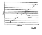
- the calibration table may divided into a plurality of segments, e.g ., 10 segments as shown in Fig. 21 , where the FIFO principle is used on a per segment basis. This approach guarantees that the calibration points remain evenly distributed over the capacity range of the pump.
- the number of segments and segment size are configurable depending upon accuracy requirements and application.
- a calibration procedure will need to be performed.
- a series of (random) dispenses is carried out to fill the calibration table.
- the calibration table can also be filled with the theoretically expected output, multiplied by a safety factor (e.g. 0.9). This will make the system somewhat slow in the beginning (because extra dispense cycles are needed to get the desired output), but it will make an initial calibration procedure unnecessary.
- the later procedure may be preferable when the powders being dispensed are costly or must be kept in a sanitary condition.
- dispense routines illustrated above are particularly useful for dispensing apparatuses utilizing rotary turntables as illustrated above, the dispense routine is applicable to other devices whereby the ingredient containers move linearly or are stationary such as the apparatus illustrated in U.S. Publication No. US 2004/0102663 .
Landscapes
- Chemical & Material Sciences (AREA)
- Chemical Kinetics & Catalysis (AREA)
- Physics & Mathematics (AREA)
- General Physics & Mathematics (AREA)
- Engineering & Computer Science (AREA)
- Automation & Control Theory (AREA)
- Basic Packing Technique (AREA)
- Loading And Unloading Of Fuel Tanks Or Ships (AREA)
- Devices For Dispensing Beverages (AREA)
- Containers And Packaging Bodies Having A Special Means To Remove Contents (AREA)
Description
- Apparatuses and methods are disclosed for dispensing a plurality of formulas volumetrically and gravimetrically using a controller having a memory that stores a plurality of formulas. The controller is linked to a plurality of pumps or conveyors, with each pump connected to a container holding one of the materials to be dispensed according to one of the formulas. The controller is also linked to a scale for measuring the amount of liquid or powder dispensed by its respective pump. The disclosed apparatuses and methods are applicable to liquid and powder ingredients.
- Multiple pump dispensing systems have been used in the paint industry. Specifically, such a dispensing system incorporating multiple pumps that dispense viscous fluids such as paint colorant from flexible packages is disclosed in
U.S. Patent No. 6,273,298 , which is commonly owned with the present application. Typically, such systems include piston pumps mounted on a rotary turntable with each pump coupled to a flexible package containing a viscous fluid, such as a paint colorant. The turntable, pumps and packages mounted thereon, are rotated until the desired pump and package is disposed over the container to be filled. A control system is utilized to rotate the table and control the action of the pumps to control the amount of material dispensed from the packages by the pumps into the container. The linear type dispensing systems are also known. - Some currently available paint colorant dispensers utilize nutating pumps and a computer control system to control the nutating pumps. Nutating pumps have a piston which is positioned inside of a housing having a fluid inlet and a fluid outlet. The piston simultaneously slides axially and rotates inside the housing. The dispense stroke or cycle can be broken down into a number of discreet steps or segments for extremely accurate volumetric dispenses. For example, a minimum dispense can be as little as 1/256 of a fluid ounce as illustrated in
U.S. Patent Nos. 6,749,402 ,6,540,486 and6,398,515 , all commonly assigned with the present application. These patents all disclose improved nutating pump technologies that are applicable to paint colorant dispensing as well as the dispensing of hair dyes, other cosmetics applications and other fluids. - Systems that dispense by volume only (i.e., not by weight) offer fast dispense times because no feedback is required. However, volumetric dispensing is not as accurate as gravimetric dispensing as air bubbles or density variations can compromise the accuracy of the amounts dispensed.
- Another approach to liquid dispensing accuracy can be found in
U.S. Patent No. 5,365,722 , which discloses a calibration scheme based on the ratio of impeller rotations to the weight of material dispensed. A first dispense amounting to about 95% of the target fill is carried out at a high flow rate followed by subsequent smaller dispenses at lower and lower flow rates until the target is reached. The low flow rates at the end of the dispense are necessary because a dispense in excess of the desired amount may result in the product being rejected. In short, once too much of an ingredient has been dispensed, there is no way to correct the error without rejecting that batch and starting over. However, this approach is slow as it requires multiple dispense cycles to reach the target and final cycles are carried out at very low flow rates. - Like paint, the color spectrum for hair dyes is broken down into dozens of different colors. Further, consumers having dry, normal or oily hair may require products especially formulated for their hair type. Specialized colors may be made for gray hair as opposed to more youthful hair. Coloring products may also be customized for curly hair, thin hair, afro, etc. Mixing ratios of the colorant and developer can vary greatly depending upon the desired effect. Therefore, in addition to the rainbow of shades that are necessary to meet public demand, stores are confronted with the significant problem of trying to stock all of the colors for the various hair types.
- To address this problem, point-of-sale hair dye dispensing machines have been developed. One such machine is disclosed in
U.S. Publication No. 2005/0087545 , which is commonly owned with the present application. The machine includes a plurality of containers for storing various colorants or dye intermediates and developer solutions that typically contain an oxidizer (e.g., hydrogen peroxide). - Similar to the hair dye problem, not all cosmetic products are universally applicable. Consumers having dry, oily or normal skin may require treatment products especially formulated for their particular condition. Hair products including shampoos, conditioners, hair dyes and permanent wave solutions are all quite sensitive to individual characteristics of the treated hair. No generic formula fits all types. Even more complicated are color cosmetics. A rainbow of shades is necessary to meet public demand. Stores find it a significant problem to stock all possible variations of a particular color cosmetic. One type of multiple formula liquid dispenser is disclosed in the commonly assigned
U.S. Patent No. 6,935,386 . - European regulations are becoming increasingly hostile to volatile organic components (VOCs). Because many liquid ingredients of paints, cosmetics and hair dyes contain VOCs, manufacturers and retailers are turning to powder ingredient and using water as a primary solvent. Therefore, powder dispensing systems have been developed. U.S. Publication Nos.
US 2005/0247730 andUS 2005/0269367 disclose multiple powder dispensing systems. - Multiple pump systems in other fields than paint dispensing are also known:
US 2003/0121561 relates to an apparatus and a process for rapidly and accurately dispensing fluids, in which at least one component is dispensed into the reaction vessel in two or three stages. In this process, the amount of fluid dispensed in the second and third stages is determined on the basis of the mass flow rate calculated in the preceding sub-step. - Further,
US 4961887 discloses an apparatus and process for manufacturing insulation for metallic rod which includes a mechanism for housing a plurality of ingredients, scales for weighing a predetermined quantity of each ingredient, a blender for blending predetermined amounts of each ingredient into one material, a mixer to mix the dry blend of ingredients, a mill to form the blended material into strips, a dicer to transform the strips into pellets of insulation, an extruder for placing insulation around the metallic rod, a conveyor to transport the ingredients and/or material between each of the above steps, a controller for outputting commands to the blender and receiving inputs from the scales to obtain the predetermined amount of each ingredient, and a computer for verifying that the correct amount of each ingredient has been obtained. The ingredients used in the manufacture of this insulation material include plasticizers, fillers, a resin, and modifiers. In the step of obtaining the correct weight of each ingredient, the controller employs multiple setpoints to gradually obtain the required ingredient weight through what is known as a dribble feed function. - The software or algorithms used to accurately dispense liquids or powders volumetrically, gravimetrically or a combination thereof tend to be complicated and require frequent calibration. As electronic scales become necessary when accuracy is paramount, electronic scales are slow operating devices and their use can increase dispense times. Further, the consumer, often with the help of a sales technician, uses the controller and software to choose the desired formulation. This process can be tedious and time consuming as the controller will require the consumer to answer numerous questions when determining the characteristics of the product to be dispensed. Then, after a formulation is chosen, the machine must execute the selected formulation, dispense the desired volume of said ingredient and then repeat the procedure for each ingredient of the selected formulation. Whether the dispense is volumetric, gravimetric or a combination of the two, the slow dispense process in combination with the selection process results in the entire operation taking several minutes or longer.
- Therefore, to satisfy the needs of today's time pressured and time conscious consumers, an improved dispensing methodology that provides for faster dispense times for multiple ingredient formulations where the ingredients may be liquid or powder or a combination of liquids and powders.
- In satisfaction of the aforenoted needs, an improved method for dispensing ingredients of a formula is provided by claim 1.
- In a refinement, values for the difference between the first half amount and the actual first half amount dispensed are inputted to the calibration table stored in a memory for use in future calculations relating to the motion of the pump. In a related refinement, values for the difference between the second half amount and the actual second half amount dispensed are also inputted to the calibration table stored for use in future calculations relating to the motion of the pump.
- In a refinement, the initial amount for each ingredient ranges from about 70% to about 95% of the target amount for that ingredient. In a further refinement of this concept, the less than the target amount is greater than 90% of the target amount. In another refinement, the additional amount (i.e., the amount remaining to be dispensed after the initial amount is dispensed") is an amount that is less than two full strokes of a piston pump if the pump is a piston pump or two rotation so the screw feeder of the metering pump if the pump is a metering pump.
- In a refinement, each of the n ingredients is provided in its own reservoir that is in communication with its own pump and the pumps or conveyors are mounted on a rotary turntable.
- In a refinement, the selecting further comprises selecting the formula from a memory in which a plurality of formulas are stored. In a related refinement, the selecting further comprises selecting a total weight of the formula to be dispensed in addition to the selecting of the formula.
- In a refinement, any calculation of the motion of the pump for a particular ingredient may comprise using a calibration table or a table of stored values that are updated at least periodically and preferably at least once during each dispense to calculate the desired motion of the pump. Preferably, there is a separate pump and a separate set of calibration values for each ingredient.
- In a refinement, the motion of each pump is executed by a stepper motor under the control of a controller and the calculating of the motion of the pump comprises using the calibration table to calculate the number of steps for the stepper motor. The using of the calibration table comprises using a linear approximation of the number of steps (S) according to an equation S = A·Vhalf + B where A and B are calculated from the calibration table using a least square method and Vhalf is the first half amount (i.e., Vremaining/2).
- In yet another embodiment, each pump is a nutating pump as opposed to a conventional piston pump.
- In a refinement, the formulas for a hair dye or a cosmetic application.
- In an embodiment, selecting a total weight of the formula to be dispensed in addition to the selecting of the formula.
- In an embodiment, the reading of the scale and accounting for the weight of the receptacle comprises zeroing of the scale.
- A dispensing system is disclosed, according to
claim 18. - Further refinements according to the dependent claims are disclosed. In particular, a plurality of flowable ingredients can be provided in individual containers and utilizing individually controlled dispense pumps that each draw one flowable ingredient from its individual container, the pumps being positionable to dispense into a common receptacle associated with a weighing device, the weighing device and pumps linked to a controller having a memory, the method comprising: operating a selected pump to move an initial assumed amount of one of the flowable ingredients that is less than a target amount for said ingredient into the container; weighing the container and determining an actual initial amount dispensed and subtracting that actual initial amount from the target amount to determine a remaining amount; dividing the remaining amount by two (2) or about two to generate a first half amount; calculating movement of the selected pump needed to dispense the first half amount of the flowable ingredient into the container; moving the pump to dispense the first half amount and weighing the container and determining an actual first half amount dispensed by the pump; comparing the actual first half amount to the first half amount and determining a first deviation determination; utilizing the first deviation determination to adjust the first half amount and calculate a second half amount; calculating movement of the pump needed to dispense the second half amount; and moving the pump to dispense the second half amount.
- The calculating of the movement of the pump needed to dispense the first and second half amounts comprises using the calibration table stored in the memory.
- In a refinement, the calculating of the movement of the pump needed to dispense the first half amount comprises using the calibration table stored in the memory, and the calibration table is modified after determining the first deviation determination and the calculating of the movement of the pump needed to dispense the second half amount comprises using the modified calibration table.
- In another refinement, the method further comprises weighing the container and determining an actual second half amount dispensed and comparing the actual second half amount to the second half amount and determining a second deviation determination and modifying the calibration table again based on the second deviation determination.
- The above method and apparatus provide for a faster dispense time for a complex formula from a point-of-sale dispensing machine. Other advantages will become apparent upon reading the following description and appended claims, and upon reference to accompanying drawings.
- For a more complete understanding of the disclosed method and apparatus, reference should be made to the embodiment illustrated in greater detail on the accompanying drawings, wherein:
-
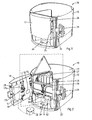
Fig. 1 is a perspective view of a multiple fluid dispensing machine made in accordance with this disclosure; -
Fig. 2 is another perspective view of the machine shown inFig. 1 with a front door and top panel in an open position and further illustrating a schematic link between the controller and the motor for rotating the turntable, between the controller and the user interface, and between the controller and the pump activator; -
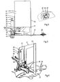
Fig. 3 is a side plan view of a pump, handle, nozzle and fluid container for a single ingredient as mounted on a rotary turntable, which is only partially shown; -
Fig. 4 is a rear perspective view illustrating the pump nozzle which is connected to the fluid container shown inFig. 3 as well as a supporting frame for the container; -
Fig. 5 is a partial bottom view of the fluid container illustrating the port which receives the pump nozzle shown inFig. 4 ; -
Fig. 6 is a partial perspective view of a plurality of pumps and containers mounted on a rotary turntable made in accordance with this disclosure; -
Fig. 7 is a partial perspective view of a plurality of pumps and containers of an alternative design mounted on a rotary turntable made in accordance with this disclosure; -
Fig. 8 is a perspective view of an apparatus for dispensing powders; -
Fig. 9 is a perspective top view of a metering pump used in the apparatus ofFigure 8 ; -
Fig. 10 is a further top view of the said metering pump; -
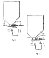
Figs. 11 and 12 are cross-sectional side views of a container and metering pump used in the apparatus ofFigure 8 ; -
Figs. 13 and 14 are perspective views of a second apparatus for dispensing powders comprising several additional features; -
Figs. 15 and 16 illustrate the use of calibration charts or formulas in accordance with the disclosed methods; -
Fig. 17 is an exemplary dispense system yield histogram for a screw-type powder dispenser; -
Fig. 18 is an exemplary calibration graph or table for a screw-type powder dispenser; -
Fig. 19 graphically illustrates the selection of a cloud or set of data points for a screw-type powder dispenser that surround the desired output Mdesired; -
Fig. 20 graphically illustrates a linear approximation of the number of steps need to dispense Mdesired using a subset or cloud of calibration data points and a reduction in the number of steps by <maximum overshoot> safety factor; and -
Fig. 21 graphically illustrates the division of a calibration data table into discrete segments and the application of the FIFO principle to individual segments. - It should be understood that the drawings are not necessarily to scale and that the disclosed embodiments are sometimes illustrated diagrammatically and in partial views. In certain instances, details which are not necessary for an understanding of the disclosed methods and apparatuses or which render other details difficult to perceive may have been omitted. It should be understood, of course, that this disclosure is not limited to the particular embodiments illustrated herein.
- Turning first to
Figs. 1 and 2 , anapparatus 10 for dispensing a plurality of different fluids, such as components of hair dyes, paints, paint colorants, nail polish, shampoos, foundations, medicaments and other multiple component liquids is illustrated. The disclosedapparatus 10 can be used for dispensing numerous recipes of these types of products and, because of its compact and aesthetically pleasing design, can be located in a retail environment, such as hair salons and spas. - The
apparatus 10 includes abase 11, one ormore side panels 12 and one or moretop panels 13. A front door is also provided which pivots to the open position shown inFig. 2 by way of the hinges shown in 15. Thedoor 14 serves as a housing for a controller shown in phantom at 16 as well as anactuator 17 that is used to operate the pumps shown at 18. Theactuator 17 may be moved by a stepper motor shown in phantom at 11. - It will be noted that the
pumps 18 are mere examples and, as this disclosure also directed to the dispensing of all flowable materials, including powders. Thus, while piston pumps 18 are shown in the figures, conveyors, such as impeller or auger-type devices are also within the scope of this disclosure. Essentially, any delivery device operable by a motor or stepper motor that can be controlled by a computer orcontroller 16 can be used as a "pump." Therefore, hereinafter and in the appended claims, the term "pump" means conventional pumps of all types (e.g., piston, gear, nutating, diaphragm, metering etc.), as well as impeller or auger-type devices which are referred to as metering pumps inFigs. 8-14 below and any device capable of being controlled and delivering a flowable material. - The
apparatus 10 also includes aninterface 21 that includes a screen 22 andkeypad 23. Also shown inFigs. 1 and 2 is thescale 24 that is operatively linked to thecontroller 16. Thedoor 14 may also include ahandle 25 andpower switch 26. - Turning to
Fig. 3 , the embodiment illustrated utilizes arotary turntable 27, which is partially shown inFig. 3 . Theturntable 27 rotates about ashaft 28 and, one means for imparting rotation to theturntable 27 can be the employment of a motor 31 coupled to a toothed wheel 32 (seeFig. 2 ) which can engage the small circumferential slots shown at 33 inFig. 4 . The motor 31 is operatively linked to thecontroller 16. Of course, other means for imparting rotation to theturntable 27 under command of thecontroller 16 will be apparent to those skilled in the art. - Returning to
Fig. 3 , typical piston pumps 18 include acylinder 34 which accommodates a slidable piston (not shown). A washer orflange 35 is attached to an end of the piston and provides for a means for engagement with the actuator 17 (seeFig. 2 ). A stop collar is shown at 36 which may also provide a means for sealing the end of thecylinder 34. - When the
door 14 is closed, theactuator 17 on the inside of thedoor 14 engages theflange 35 of the pump that is in the front position, or the position in alignment with theactuator 17. Theactuator 17 includes an upper leg 17a and alower leg 17b with a gap disposed therebetween for receiving aflange 35. In a preferred embodiment, after a material is dispensed by one of thepumps 18, the movement ofactuator 17 via themotor 19 empties any material remaining in thecylinder 34 back into his respective container so that there is no residual material left in the pump. - This is the preferred methodology for two reasons. First, the material contained within the containers or
bags 37 may be oxygen sensitive and exposure of the ingredient material to oxygen may be limited if the material is returned to its bag after dispensing. Also, by returning theactuator 17 to the position shown inFig. 2 , theactuator 17 is in alignment with theflanges 35 of thepumps 18 while they are in their down or empty position and therefore theactuator 17 allows unobstructed horizontal movement of thepumps 18 andflanges 35, but engages aflange 35 of apump 18 when theactuator 17 is moved vertically. Upward movement of theactuator 17 causes an intake stroke of the piston and downward movement causes a discharge stroke. - Returning to
Fig. 3 , thecylinder 18 is mounted on top of apump housing 38 which contains a valve, such as a ball valve, which can be operated by alever 41. In the intake position of thelever 41, thecylinder 34 communicates with thecontainer 37 via the connector ornozzle 42 so that thecylinder 34 can be filled with a desired amount of fluid by moving theflange 35 upwards over a desired or predetermined length under the action of theactuator 17 as determined by thecontroller 16. As soon as the intake stroke has been completed, the valve member is rotated by moving thelever 41 to a dispense position that fluid can be discharged by moving theflange 35 andactuator 17 downwards. Fluid is dispensed out thepump 18 through a nozzle shown at 43. To move thelever 41 from the intake to the dispense position, anadditional actuator 44 is provided in thedoor 14. Also, as noted above, after the dispense is complete and it is desired to discharge any remaining material from thecylinder 34 back into the container orbag 37, thelever 41 is moved back to the intake position and the dispense stroke is completed by lowering theflange 35 andactuator 17 to the fully downward position as the material is evacuated from thecylinder 34 back into itscontainer 37. - Turning to
Figs. 4 and 5 , theconnector 42 is secured to thepump housing 38 as shown and provides a male connection to the container orbag 37 shown inFig. 5 . With thecap 44 removed, theconnector 42 is received within the bag and provides a sealed connection. To remove thebag 37 orcontainer 37 from theconnector 42 and pump 18, alever 45 is provided which includes a frame 46 that engages thecorresponding frame 47 on thecontainer 37. Pivotal movement of thelever 45 in the downward direction causes upward movement of the frame 46 which engages theflange 47 of thecontainer 37 which acts to dislodge thecontainer 37 from theconnector 42. - To hold the
container 37 in place, asuitable holder 51 is provided with front andrear walls holder 51 is secured to theturntable 27 as shown inFig. 4 . Theholder 51 also provides a pivot for thelever 45 and frame 46. -
Figs. 6 and 7 illustrate a few alternatives for the arrangement of thevarious containers 37 shown inFigs. 2 and3 andlarger containers Fig. 6 and 7 . Thelarger containers Fig. 6 , two of thelarger containers 54a may be employed or, as shown inFig. 7 , four of thelarger containers 54b may be employed. Other various arrangements including a single larger container or more than four larger containers or an odd number of larger containers can be easily accommodated for and will be apparent to those skilled in the art. - Referring back to
Fig. 1 , it will be noted that thescale 24, the motor 31, theactuator 44 and theactuator 17 are all linked to thecontroller 16. Thecontroller 16 is also operatively linked to theinterface 21. With this communication in mind, attention is now directed to the improved dispensing method, one embodiment of which is illustrated inFigs 15-17 below. - Turning to
Fig. 8 , anapparatus 100 for dispensing a plurality of powders, such as pigments for compounding paints, dyes, caulking or grout or components of cosmetics, e.g. foundations is disclosed. Theapparatus 100 can be used for numerous paint or cosmetic recipes and can be located e.g. at a retailer, a spa or at a body repair shop for cars. - This
particular dispensing apparatus 100 is an automated version and includes ahorizontal turntable 102, mounted on asupport 103 and carrying, along its circumference, a plurality of metering powder pumps 104 and twenty-fourcontainers 105 for the powders. Theturntable 102 can be rotated about a vertical, central axis by means of a motor inside thesupport 103 and between discrete positions, in this case forty-eight positions (two for each container as will become apparent below) including a front or dispensing position provided with astepper motor 106 for driving one of thepumps 104. - The
apparatus 100 further comprises acontrol device 107 comprising asmall keyboard 108 for entering information, such as client data and paint recipes, and adisplay 109. Thecontrol device 107 also comprises a computer orcontroller 110 for storing the said information and for driving theturntable 102 and thestepper motor 106. - A weighing
device 111, comprising an upper plate on which a cup or other receptacle can be placed and a load-cell (hidden from view and known in itself), is located beneath thepump 104 and thecontainer 105 that are in the dispensing position. Optionally, a dispenser (not shown) for cups or other receptacles can be provided, especially when theapparatus 100 is being employed for dispensing components of cosmetics. - As can be seen in
Figures 9 and 10 , each of the metering pumps 104 comprises ahousing 112 having ainlet chamber 113, with an inlet opening facing upwards and positioned beneath acontainer 105, and a polycylindrical bore (shown in cross-section inFigs. 11 and 12 ) leading to anoutlet chamber 114 facing downwards and, during dispensing, positioned over areceptacle 115. Alid 116 is pivotally mounted on thehousing 112 for closing theoutlet chamber 114. - As shown in
Figs. 11 and 12 , inserts 117 are mounted, e.g. by means of an external screw thread, in the channel between thechambers inserts 117 are provided with axially extending pump chambers, which accommodate two concave profile screws, impellers or augers 118 of different size and which can be readily replaced, e.g. when a different type or size of screw is to be fitted. - In this example, the screws 118 extend radially with respect to the
turntable 102. The relativelylarge screw 118A has a diameter of 22 mm and a double pitch of 12 mm, yielding a dispensed volume for each revolution of 735 mm3, whereas the relativelysmall screw 118B has a diameter of 8.5 mm and a double pitch of 7 mm, yielding a dispensed volume for each revolution of 35 mm3. First ends of the screws 118, extending away from the central vertical axis of theturntable 102, are each provided with anadaptor 119 which is to be engaged by thestepper motor 106, as will be explained in more detail below. Further, each of the screws 118 is made of polypropylene (PP) or polytetrafluoroethylene (PTFE) reinforced with acylindrical metal rod 120. - In order to further improve the dispensing accuracy of the screws 118, the effective outer diameter of the screws 118 is in excess of the effective inner diameter the respective channel. The rim of the screw is at least partially bent in the displacement direction of the pump. Such bending can be achieved by simply inserting the oversized screws in the channels from the outlet side towards in the inlet side.
- In an alternative embodiment, which is especially suitable for fragile powders, the effective outer diameter of the screw is smaller than the effective inner diameter of the respective channel, resulting in clearance between the screw and the channel, and wherein the screw is provided with bristles that bridge this clearance. This type of screw was found to be effective in reducing the forces exerted on the powder.
- As illustrated in
Figures 11 and 12 , during the dispensing of a particular recipe, e.g. consisting of powders to be dispensed and mixed in a cup or consisting of a base material into which one or more powders should be dispensed, theturntable 102 is rotated about its vertical axis until thecontainer 105 with the required powder is in the dispensing position. Subsequently, thelid 116 is opened (seeFigure 12 ) and, depending on the amount to be dispensed, thelarge screw 118A, which a particular powder having a density of, say, 0.57 g/cm3 dispenses 0.42 g for each revolution, or thesmall screw 118B, which dispenses 20 mg for each revolution, is selected. - The accuracy of the screws can be further enhanced by calibrating, relative to a reference or zero position of the screw, the dispensed amounted in several positions within one revolution, e.g. for each step of 30 degrees yielding a total of 12 steps in one revolution. By calibrating for several positions, any non-linear effects can be taken into account. These effects dependent inter alia on the dimensions and material of the screw and on the powder that is being dispensed. In some cases, the screw will dispense relatively small amounts or not dispense at all during e.g. two or three steps and then dispense a relatively large amount in the fourth step, which phenomenon could be referred to as "pulsing". Many of these effects were found to be sufficiently regular to allow compensation by calibration.
- In addition to use during dispensing, the above-described weighing
device 111 can also be used to calibrate one or more of thepumps 104 as discussed with respect toFigs. 15 and 16 below. - Once dispensing of a particular powder has been completed, the
lid 116 is closed and theturntable 102 is rotated until the next requiredcontainer 105 is in the dispensing position. Closing thelid 116 prevents powder from falling out during rotation. In an alternative embodiment, the screws that have just been used are revolved in reverse direction prior to rotation of the turntable thus drawing the powder back into the metering powder pump. -
Figures 13 and 14 show a second embodiment of anapparatus 100A for dispensing powders comprising several additional features. This second embodiment comprises substantially the same components as the embodiment described above, including ahorizontal turntable 102, with a plurality of metering pumps 104 andcontainers 105, mounted along its circumference as shown inFig. 8 . Theturntable 102 can be rotated between discrete positions, in this example, forty-eight positions including a front or dispensing position (marked infigure 13 by a single exposed container), about a vertical, central axis by means of a drive (not shown). Theapparatus 100A includes a frame of e.g. aluminum extrusion profiles 121 to whichsheets 122 of metal or a polymer (transparent, translucent or opaque) have been attached by means of e.g. screws. A control device comprising adisplay 109 and akeyboard 108 for entering information, such as customer data and recipes, is mounted on the right hand side of the frame, next to adoor 123. Thisdoor 123 contains acomputer 110 for storing the said information and for driving theturntable 102, actuators, including astepper motor 106, for operating thepumps 104, etc. A weighingdevice 111 is positioned below thedoor 123 in a space where acontainer 115 or the like for receiving powders dispensed by theapparatus 100A can be placed. - A substantially
rectangular hatch 124 is pivotally mounted, along one of its rims, in thetop sheet 122. Further, ametal coversheet 125 is present below thehatch 124. Thecoversheet 125 comprises anopening 126 that corresponds in shape to the shape of thecontainers 105 and which consequently allows access to only onecontainer 105 at a time. - A ventilation unit is located below the turntable, which comprises a
grille 127 and which will remove airborne powder. Further, an ionisation device 128 (e.g., a Static Eliminator AD1683EX, available from A&D Company, Ltd., Tokyo, Japan) is provided near, preferably around the dispensing opening of thepump 103 of the container 4 in the dispensing position. Thisionisation device 128 serves to reduce or even neutralise electrostatic charges in the material that is being dispensed, thus preventing this material from adhering to thepump 104 or other parts of thedispenser 100A and improving the accuracy with which the powder is dispensed. - The dispensing methods will now be described. For each apparatus above, including the
apparatus 10 intended primarily for liquid ingredients and theapparatuses pump 118, 104 for the first part or first half. - This procedure takes advantage of the concept that the output variance of any device, such as a pump, is smaller and more consistent in the short term or for small outputs. So, for any particular ingredient that requires accuracy, the bulk of the dispense, short of the target amount, is carried out and weighed. The remaining amount is calculated and divided, preferably by two (2). The first part of the remaining amount, or the first half, is dispensed and weighed. The difference between the weighed amount (actual amount) for the first half and the calculated or intended amount for the first half is used to build in a correction for the second part or second half. In an embodiment, this error or difference is doubled and added to the second half. If the weighed or actual amount for the first half is too high, the second half is proportionately reduced to correct for the first half as well as the second half; if the actual amount for the first half is too low, the second half is proportionately increased to correct for the first half as well as the second half. Thus, the correction for the first half and the projected correction for the second half are made at the same time.
- If a piston pump is used, the initial dispense preferable leaves a volume of less than two full piston strokes. Again, the objective is to take advantage of the fact that the output variance of any statistical process (including a dispense process) is much smaller in short term than in long term. This fact is known from the statistical process analysis (e.g., six sigma (σ)). Experimental measurements have shown that the mean of any given process will tend to shift +/- 1.5 σ over time. As a result, a short term samples will have a 1.5σ smaller variance than sample populations gathered over longer long term periods.
- The general dispense process for a piston pump (as well as a metering pump) may be as follows:
- A. Divide the target amount into an initial dispense (70-95% of the target) and a remaining amount that is smaller than two pump strokes (or two rotations of a metering pump screw);
- B. Carry out the initial dispense and measure the output;
- C. Calculate the remaining desired amount needed to reach the target and divide the remaining amount by a factor, e.g., by two to divide it into two halves or a number greater than two, e.g., by three to divide it into thirds;
- D. Calculate the number of pump steps or a motion of the pump for the first 'half' from the data in the calibration table or a calibration formula stored in the memory of the controller;
- E. Dispense the first half and weigh the actual first half output;
- F. Establish a differential between the expected first half amount and actual of the first half amount;
- G. Adjust the second half amount (which is often the same as the intended first half amount) by double this differential (once for the dispense of the first half, and once again to compensate for the expected deviation in dispense of the second half);
- H. Calculate the steps or a motion of the pump needed for the "adjusted" second half, dispense and verify the actual second half output
- When the actual output is more than the allowed upper limit tolerance, the dispense is rejected, when the actual output is less than the lower limit tolerance, the missing amount is dispensed (typically in one go when the amount is smaller than 0.1 ml or <0.5mg).
- When the remaining amount (after the initial dispense) is larger than two full pumps strokes for a piston pump or two rotations of a metering pump, a number of full pump strokes or rotations is preferably dispensed first until the remaining amount can be dispensed in two pump strokes or two rotations. To save time, the verification of actual output by the scale only has to take place after all full strokes have been completed. The desired (remaining) dispense output (Vremaining) is preferably divided into two equal halves (Vremaining/2). The required piston movement to realize Vremaining/2 is established using a dispense yield memory table or calibration table stored in the memory of the controller or other suitable memory device.
- In the calibration table (shown in the form of a graph in
Fig. 15 ), the number of stepper motor steps S is plotted against the desired amount Vremaining for previous dispenses. This calibration table ofFig. 15 stores the long-term relationship data between stepper motor steps S and amounts V. When Vremaining - Vactual is smaller than a certain threshold amount (typically 0.1 ml) the dispense need not be divided into two halves but can dispensed in one step. - With every dispense of a first half, where V1 remaining = Vremaining/2, the number of steps is estimated using a linear equation S1 = A * V1 remaining + B. The coefficients A and B are estimated from the calibration table using a least square method on a set of N nearest points. A typical value for N is 5 as shown in
Fig. 17 . N may vary from liquid to liquid and may be very different for powders as opposed to liquids. - The actual yield from the "half" dispense of Vremaining/2, as measured by the scale (V1 actual), is used to predict the yield for the second "half" dispense. The second "half" dispense will need to be adjusted such that the deviation in the dispense of the first "half" (i.e., V1 remaining - V1 actual) is compensated for as well as the expected deviation for the second "half" dispense. The missing or superfluous amount that occurred during the first dispense action (i.e. V1 remaining - V1 actual) is likely to occur during the dispense of the second 'half' is assumed to be approximately as big as the deviation that occurred in the first 'half'. Thus, using the previously established linear relationship, S = A * V1 remaining + B, piston travel (S2) is now calculated the second half, S2 = A * V2 remaining + B, where V2 remaining = V1 remaining + 2 * (V1 remaining - V1 actual). Preferably, the dispense of the first half is not yet added to the calibration table and the calibration table is updated after the second dispense.
- The calculated piston travel (S2) is now used to perform a dispense action and the end result V2 actual is measured.
- After the second half dispense (the third dispense in all), the actual and desired outputs are compared (V2 remaining - V1 actual). When the actual output does not fall within the specified tolerances the missing amount has to be dispensed. When the remaining V2 remaining - V2 actual is smaller than a certain threshold (typically 0.1 ml or 0.5 mg) the missing amount is dispensed in one dispense action, otherwise the procedure for a Vremaining is carried out as set forth above.
- A typical calibration table (
Figs. 15 and 16 ) contains 50 data points or more. The calibration table is preferably updated automatically with every dispense cycle. Every new dispense add a new co-ordinate (Vremaining, S) to the table and the oldest coordinate may be deleted according to the so called First in First out principle (FIFO). Without additional measures this approach can lead to a situation where the calibration table is unevenly distributed when a large series of 'close together' dispenses is carried out. Therefore the calibration table is divided into typically 10 segments where the FIFO principle is used per segment. This approach ensures that the calibration points remain evenly distributed over the capacity range of the pump. The number of segments and segment size are configurable depending upon accuracy requirements and application. - Initially (when the dispenser has never been used before) a calibration procedure will need to be perform a series of (random) dispenses to fill the calibration table. Alternatively the calibration table can also be filled with the theoretically expected output, multiplied by a safety factor (e.g., 0.9). This will make the system somewhat slow in the beginning (because extra dispense cycles are needed to get the desired output), but it will make a calibration procedure unnecessary. Properties of data recording like recording capacity, distribution of measurements over range etc. are configurable.
- While dividing the remaining amount by two (2) to create first and second half amounts is preferable for speed purposes, the remaining amount may be divided into thirds, fourths, fifths, or even non-equal portions. The important point is for the "error" made in the first or one remaining amount dispense to be applied to a second or successive remaining amount dispenses.
- Next, an algorithm is described that is particularly useful for dispensing of powders and/or granulates (referred to as powders in the rest of this document) using a multiple lead screw dispensing system having feedback from a scale. The particular algorithm ensures that a desired amount of powder is dispensed within prescribed tolerance limits (upper and or lower) with as little iteration cycles as possible.
- The dispensing of powders can be more difficult than liquids. This is primarily caused by two phenomena. First, the density (amount of material per unit of volume) of a powder can vary greatly with the particle size and compaction. Second, the yield of a lead screw dispensing system varies with the "flow properties" of the powder (i.e. particulate size, particulate shape and particulate surface friction). Due to these two phenomena, the existing dispense algorithms for gravimetric feedback of liquids do not function correctly. The short term variation in a powder dispense system yield is too large to rely on short term repeatability as is done in the gravimetric algorithm for liquids.
- A disclosed algorithm dispenses powders in an iterative approach. An example of a distribution of the system output is shown in
Fig. 17 . Sometimes the system output is below average, sometimes above average. To avoid over-dispensing and a rejected dispense, the algorithm uses a safety margin. The safety margin is established using the recorded historical maximum overshoot as shown inFig.17 . This safety margin is recalculated per dispense using a subset of the recorded history. This is described in greater detail below. The disclosed mechanism makes the algorithm self-learning. - To illustrate a dispense cycle, it will be assumed the system has generated a set of dispense results with the number of steps and the associated powder output mass. The set of collected points (number of steps, mass of powder output) is called the "calibration table and is illustrated in
Fig 18. Fig. 18 covers a range between 0 steps and 0 mass output and a predefined <upper limit>. - Before every dispense, action the algorithm will select a subset or a "cloud" of the n nearest points in the neighborhood of the desired output mass as shown in
Fig. 19 . Within the cloud of points ofFig. 19 , the algorithm will construct a linear relationship between output and number of steps needed to reach the desired output. Also the safety "shift," i.e. the reduction to avoid and over-dispense, is calculated from this cloud of points. The safety shift is defined as the maximum overshoot multiplied by a safety factor and is illustrated inFig. 20 . This safety factor is a general system setting. The more historic points are stored in the system, the smaller the safety factor can be. To avoid very slow dispensing following a stray measurement, the system limits the safety shift to an adjustable absolute <maxshift> value. - Depending on the properties of the powder and the desired accuracy tolerances, the above described powder algorithm requires three to four iteration cycles to reach target. A typical powder dispensing system contains two (or more) lead screws including a large screw or impeller and a small screw or impeller. The lead screws are dimensioned such that yield per step is significantly different to obtain a high dispense accuracy.
- The data sets used in the powder algorithm (
Figs. 18-20 ) are specific for each lead screw, which in turn are typically dedicated to a single powder as shown inFigs. 8-12 . Within each dispense cycle, the algorithm will use the lead screw (and corresponding data set) where the <upper limit> is larger than the requested amount. When the requested amount is larger than the table upper limit. The amount will be split-up the dispense in a multiple cycles of <upper limit> amounts. - Preferably, the algorithm automatically updates the calibration tables for the lead screws.
- The calibration table may typically contain 100 points. The calibration table may be updated with every dispense cycle. Every new dispense add a new co-ordinate (Mdispensed, S) to the table and the oldest coordinate will be deleted according to the so called First in First out principle (FIFO). Without additional measures this approach can lead to a situation where the calibration table is unevenly distributed when a large series dispenses of similar amounts (e.g., 5g) is carried out. To address this issue, the calibration table may divided into a plurality of segments, e.g., 10 segments as shown in
Fig. 21 , where the FIFO principle is used on a per segment basis. This approach guarantees that the calibration points remain evenly distributed over the capacity range of the pump. The number of segments and segment size are configurable depending upon accuracy requirements and application. - Initially, when the
dispenser 100 has never been used before, a calibration procedure will need to be performed. In this procedure a series of (random) dispenses is carried out to fill the calibration table. Alternatively the calibration table can also be filled with the theoretically expected output, multiplied by a safety factor (e.g. 0.9). This will make the system somewhat slow in the beginning (because extra dispense cycles are needed to get the desired output), but it will make an initial calibration procedure unnecessary. The later procedure may be preferable when the powders being dispensed are costly or must be kept in a sanitary condition. - Therefore, another general dispense routine may be summarized in the following steps:
- A. When the requested amount is larger than the <upper limit> (see
Fig. 18 ), as many cycles of <upper limit> are dispensed until the remaining amount is smaller than <upper limits>. - B. Select the lead screw that has the smallest <upper limit> that is still larger than the requested (remaining) amount.
- C. Select a cloud of <n> nearest points from the calibration table around the requested amount (
Fig. 19 ). - D. Construct a linear equation from the cloud of points using the least squares method (
Fig. 20 ). - E. Calculate the maximum overshoot from the cloud and shift the linear equation by a <safety factor> * <maxovershoot> to the right (
Fig. 20 ).. - F. Calculate the number of steps by substituting the requested amount in the shifted equation. To avoid very slow dispensing following a stray measurement, the system limits the shift to an adjustable <maxshift> value.
- G. Dispense the calculated steps and measure the system yield.
- H. Store the steps, actual output and requested output in the calibration history table and delete the oldest calibration point in the table segment (
Fig. 21 ). - I. Repeat the above process from step 2 as long as the yield is below the tolerance on the requested amount. The process is aborted (fails) when the yield is higher than the requested amount + allowed tolerance.
- While the dispense routines illustrated above are particularly useful for dispensing apparatuses utilizing rotary turntables as illustrated above, the dispense routine is applicable to other devices whereby the ingredient containers move linearly or are stationary such as the apparatus illustrated in U.S. Publication No.
US 2004/0102663 .
Claims (19)
- A method for dispensing a plurality of ingredients of a formula, the method comprising:a) selecting a formula calling for n ingredients, with each ingredient having a target amount, wherein n is an integer;b) calculating a motion of a pump (18, 104, 118, 118A, 118B) required to dispense an initial amount of one of the n ingredients that is less than the target amount of said one of the n ingredients;c) executing a percentage of said motion of the pump required to dispense said initial amount;d) reading a scale (24) and determining an additional amount of said one of the ingredients needed to meet the target;e) calculating a motion of the pump required to dispense a first half amount based on a calibration formula;f) executing said motion of the pump required to dispense said first half amount and reading the scale to determine an actual first half amount dispensed;g) subtracting the actual first half amount dispensed from said first half amount to generate a first difference to calculate a second half amount and calculating a motion of the pump required to dispense said second half amount; andh) executing said motion of the pump required to dispense said second half amount,
characterized in that
step (e) further comprises dividing said additional amount by 2 to calculate said first half amount;
in that step (g) further comprises multiplying the difference by 2 and adding the result to said first half amount to calculate said second half amount;
in that the motions of the pump are executed in steps under the control of a controller (16, 110) and the calculating of the motions of the pump comprises using a calibration table comprising a set of data points to calculate a number of steps for the motion of the pump, each data point corresponding to a number of steps and an amount of said one of the ingredients
and in that the using of the calibration table comprises using a linear approximation of the number of steps (S) according to an equation S = A·V + B where A and B are calculated from the calibration table using a least square method and V is the first half amount for step (e) and the second half amount for step (g). - The method of claim 1 further comprising:i) reading the scale (24) to determine an actual amount dispensed after the dispensing of said second half amount.
- The method of claim 2 further comprising:j) if the reading of the scale (24) indicates that more of said one of the n ingredients is needed to meet the target amount, repeating parts (e) through (h).
- The method of claim 1 further comprising:i) repeating parts (b) through (h) for each of said n ingredients.
- The method of claim 1 wherein said initial amount that is less than the target amount of part (b) ranges from about 70% to about 95% of the target amount.
- The method of claim 1 wherein the pump (18) is a piston pump and the additional amount of part (d) is an amount that is less than two full strokes of the piston pump.
- The method of claim 1 wherein the pump is a metering pump (104) and the additional amount of part (d) is an amount less than two rotations of a screw feeder (118, 118A, 118B) of said metering pump.
- The method of claim 1 further comprising placing a receptacle (115) on the scale (24) and reading the scale and accounting for a weight of the receptacle.
- The method of claim 1 wherein each of the n ingredients is provided in its own reservoir (37, 54a, 54b,105) that is in communication with its own pump (18, 104, 118, 118A, 118B) or conveyor and the pumps or conveyors are mounted on a rotary turntable (27, 102).
- The method of claim 1 wherein the selecting further comprises selecting the formula from a memory in which a plurality of formulas are stored.
- The method of claim 10 wherein the selecting further comprises selecting a total weight of the formula to be dispensed in addition to the selecting of the formula.
- The method of claim 1 wherein the motion of each pump is executed by a stepper motor (19,106) under the control of a controller and the calculating of the motion of the pump in part (e) comprises using a calibration table to calculate the number of steps for the stepper motor.
- The method of claim 1 wherein new values for S, A and B are calculated at least once for each dispense and stored in the calibration table.
- The method of claim 1, wherein the ingredients are flowable ingredients provided in individual containers (37, 54a, 54b, 105), and wherein individually controlled dispense pumps (18, 104, 118, 118A, 118B) each draw one flowable ingredient from its individual container, the pumps being positionable to dispense into a common receptacle (115) associated with the scale (24), the scale and pumps linked to the controller (16) having a memory.
- The method of claim 14 wherein the calibration table is stored in the memory.
- The method of claim 15 wherein
the calibration table is modified after determining the first difference and the calculating of the movement of the pump needed to dispense the second half amount comprises using the modified calibration table. - The method of claim 16 further comprising weighing the receptacle (115) and determining an actual second half amount dispensed and comparing the actual second half amount to the second half amount and determining a second difference and modifying the calibration table again based on the second difference.
- A flowable ingredient dispenser comprising:a scale (24); the scale linked to a controller (16, 110), the controller comprising a memory with a plurality of formulas, each formula comprising n amounts of n ingredients, wherein n is an integer, the controller selectively linked to a plurality of pumps (18, 104, 118, 118A, 118B) by an activator, each pump coupled to a separate reservoir containing one of said ingredients, the controller being linked to a user interface (21, 22, 23, 108), the controller being programmed to receive an instruction from a user interface to execute the dispensing of one of said formulas, and the controller being further programmed to, upon receiving said instruction, carry out a sequence comprisinga) selecting a formula calling for n ingredients, with each ingredient having a target amount, wherein n is an integer;b) calculating a motion of the pump required to dispense an initial amount of one of the n ingredients that is less than the target amount of said one of the n ingredients;c) executing a percentage of said motion of the pump required to dispense said initial amount;d) reading a scale and determining an additional amount of said one of the ingredients needed to meet the target;e) calculating a motion of the pump required to dispense a first half amount based on a calibration formula stored in the memory;f) executing said calculated motion of the pump required to dispense said first half amount and reading the scale to determine an actual first half amount dispensed;g) subtracting the actual first half amount from said first half amount to generate a first difference to calculate a second half amount;h) calculating a motion of the pump required to dispense said second half amount; andi) executing said motion of the pump required to dispense said second half amount;characterized in thatstep (e) further comprises dividing said additional amount by 2 to calculate said first half amount;in that step (g) further comprises multiplying the first difference by 2 and adding the result to said first half amount to calculate said second half amount;in that the motions of the pump are executed in steps under the control of the controller and the calculating of the motions of the pump comprises using a calibration table comprising a set of data points to calculate a number of steps for the motion of the pump, each data point corresponding to a number of steps and an amount of said one of the ingredientsand in that the using of the calibration table comprises using a linear approximation of the number of steps (S) according to an equation S = A·V + B where A and B are calculated from the calibration table using a least square method and V is the first half amount for step (e) and the second half amount for step (g).
- The flowable ingredient dispenser of claim 18, wherein the sequence further comprisesj) reading the scale (24) to determine an actual second half amount dispensed, subtracting the actual second half amount from said second half amount to generate a second difference;k) using at least one of the first or second differences or both to modify the calibration formula.
Applications Claiming Priority (2)
| Application Number | Priority Date | Filing Date | Title |
|---|---|---|---|
| US11/251,584 US7527078B2 (en) | 2005-10-13 | 2005-10-13 | Apparatuses for dispensing materials volumetrically and gravimetrically based on a stored formula and methods of dispensing formulas using the same |
| PCT/US2006/035479 WO2007046978A1 (en) | 2005-10-13 | 2006-09-12 | Apparatus and method for dispensing materials volumetrically and gravimetrically based on a stored formula |
Publications (2)
| Publication Number | Publication Date |
|---|---|
| EP1949199A1 EP1949199A1 (en) | 2008-07-30 |
| EP1949199B1 true EP1949199B1 (en) | 2014-01-22 |
Family
ID=37686165
Family Applications (1)
| Application Number | Title | Priority Date | Filing Date |
|---|---|---|---|
| EP06814509.3A Not-in-force EP1949199B1 (en) | 2005-10-13 | 2006-09-12 | Apparatus and method for dispensing materials volumetrically and gravimetrically based on a stored formula |
Country Status (4)
| Country | Link |
|---|---|
| US (1) | US7527078B2 (en) |
| EP (1) | EP1949199B1 (en) |
| CN (1) | CN101322087B (en) |
| WO (1) | WO2007046978A1 (en) |
Families Citing this family (63)
| Publication number | Priority date | Publication date | Assignee | Title |
|---|---|---|---|---|
| US7893366B2 (en) * | 2007-02-20 | 2011-02-22 | Gaalswyk Mark K | Method of weigh batching for selected batch formula and batch size |
| US7967037B2 (en) * | 2007-06-14 | 2011-06-28 | Calgary Scale Services (1988) Ltd. | Apparatus and system for dispensing liquids |
| WO2009076375A1 (en) * | 2007-12-10 | 2009-06-18 | E. I. Du Pont De Nemours And Company | Multi-product dispensing system for granular materials |
| US8567455B2 (en) | 2008-03-03 | 2013-10-29 | SureTint Technologies, LLC | Blending station apparatus and method for using the same |
| US8336582B2 (en) | 2008-03-03 | 2012-12-25 | Saranow Mitchell H | Method and system for the preparation of hair dye colors |
| US9149108B2 (en) | 2011-02-24 | 2015-10-06 | SureTint Technologies, LLC | System and method for batch sizing hair dye mixtures |
| US11235298B2 (en) | 2008-03-03 | 2022-02-01 | SureTint Technologies, LLC | Blending station apparatus and method for using the same |
| US7963303B2 (en) * | 2008-03-03 | 2011-06-21 | The Saranow Group, Llc | Manual hair dye apparatus and method for using the same |
| US11246395B2 (en) | 2008-03-03 | 2022-02-15 | SureTint Technologies, LLC | Color conversion system and method |
| US9414665B2 (en) | 2008-03-03 | 2016-08-16 | SureTint Technologies, LLC | Blending color and control management system |
| US8897915B2 (en) | 2008-03-03 | 2014-11-25 | SureTint Technologies, LLC | Inventory security management for a hair dye storage system |
| US9177339B2 (en) | 2008-03-03 | 2015-11-03 | Sure Tint Technologies, LLC | System and method for color preparation and management |
| US8393363B2 (en) * | 2008-03-03 | 2013-03-12 | SureTint Technologies, LLC | Blending station apparatus and method for using the same |
| US8141599B2 (en) * | 2008-06-17 | 2012-03-27 | Valspar Sourcing, Inc. | Expanded color space architectural paint and stain tinting system |
| EP2135668B1 (en) * | 2008-06-20 | 2013-08-21 | Fillon Technologies | Device for storing, selecting and dispensing base colours for paint, in particular for automotive paint |
| EP2145677B1 (en) * | 2008-07-16 | 2012-02-29 | Fillon Technologies | Apparatus for storage, selection and distribution of a range of products, in particular a series of base tints for automotive paint |
| US8561656B2 (en) * | 2008-10-31 | 2013-10-22 | Michael Eginton | Adaptable bench top filling system |
| EP2184590B1 (en) * | 2008-11-10 | 2012-08-22 | Mettler-Toledo AG | Dosing device with an exchangeable device for dosing units |
| US8413847B2 (en) | 2010-05-27 | 2013-04-09 | Fluid Management Operations Llc | Rotary nozzle recirculation systems |
| US8448823B2 (en) * | 2011-01-07 | 2013-05-28 | Fast & Fluid Management B.V. | Apparatus for dispensing a plurality of fluids with removable actuator module |
| GB201101075D0 (en) | 2011-01-21 | 2011-03-09 | Labminds Ltd | Automated solution dispenser |
| IT1403834B1 (en) * | 2011-02-03 | 2013-10-31 | Cps Color Equipment Spa | DISPENSE EQUIPMENT FOR FLUID PRODUCTS |
| ITTO20110232A1 (en) * | 2011-03-14 | 2011-06-13 | Hero Europ S R L | AUTOMATIC TINTING. |
| US10143984B2 (en) * | 2011-03-28 | 2018-12-04 | Fast & Fluid Management B.V. | Method and apparatus for dispensing liquids from a plurality of cartridges |
| US20130074982A1 (en) * | 2011-09-28 | 2013-03-28 | Gfi Innovations, Inc. | Methodology and Apparatus for Storing and Dispensing Liquid Components to Create Custom Formulations |
| GB2519890B (en) * | 2012-07-18 | 2019-01-16 | Labminds Ltd | Automated solution dispenser |
| US9469463B2 (en) | 2013-08-29 | 2016-10-18 | Tastetro, Inc. | Automated dispenser and method for dispensing |
| US9591943B2 (en) * | 2013-08-29 | 2017-03-14 | Tastetro Inc. | Automated dispenser and method for dispensing |
| US9622401B2 (en) * | 2014-01-27 | 2017-04-18 | Kinze Manufacturing, Inc. | Meter for dispensing a granular product |
| US10813503B2 (en) | 2014-09-09 | 2020-10-27 | Casabots Inc. | Automated food making apparatus |
| US11918150B2 (en) | 2014-09-09 | 2024-03-05 | DoorDash, Inc. | Enhanced automated food making apparatus |
| US11284748B2 (en) * | 2014-09-09 | 2022-03-29 | Chowbotics | Enhanced automated food making apparatus |
| US20170326514A1 (en) * | 2014-10-28 | 2017-11-16 | Luca Drocco | Openable tintometric machine |
| JP2018507103A (en) | 2015-02-06 | 2018-03-15 | ラブマインズ リミテッド | Automated solution dispenser |
| US10893765B2 (en) * | 2015-06-26 | 2021-01-19 | Kitchen Mate Inc. | System and method of an attachable spice dispensing device for an automatic meal preparation apparatus |
| WO2017095999A1 (en) | 2015-12-04 | 2017-06-08 | Carefusion 303, Inc | Carousel for automatic drug compounder |
| US20240127173A1 (en) * | 2016-05-20 | 2024-04-18 | Quis T. Bakir | Using captured recipes to generate tailored haircut treatments |
| US11010708B2 (en) * | 2016-05-20 | 2021-05-18 | JDS Associates Inc. | System, apparatus, and method for networked hair salon product pumps |
| ITUA20163727A1 (en) * | 2016-05-24 | 2017-11-24 | Weightpack Srl | FILLING MACHINE OF CONTAINERS WITH DIFFERENT TYPES OF PRODUCTS |
| EP3318318A1 (en) * | 2016-11-04 | 2018-05-09 | Fast&Fluid Management B.V. | Dispensing apparatus and releasably connectable fluid container for use in such dispensing apparatus |
| WO2018089371A1 (en) * | 2016-11-09 | 2018-05-17 | Farouk Systems, Inc. | Method and apparatus for analyzing and treating hair |
| US10934151B2 (en) | 2017-07-28 | 2021-03-02 | Swimc Llc | Tinting water-borne and solvent-borne paints and stains with water-only colorants |
| US10933389B2 (en) * | 2017-07-28 | 2021-03-02 | Swimc Llc | Tinting water-borne and solvent-borne paints and stains with powdered colorants |
| CN111479487A (en) * | 2017-10-23 | 2020-07-31 | 高木昭成 | Device for providing material for hairdressing medicine and method for producing the same |
| WO2019202534A1 (en) * | 2018-04-19 | 2019-10-24 | Church & Dwight Co., Inc. | Apparatus, system, and method for filling a chambered package |
| US10982939B2 (en) | 2018-07-09 | 2021-04-20 | Bushnell Inc. | Dual barrel powder dispenser |
| EP3821215A4 (en) | 2018-07-09 | 2022-03-30 | Bushnell, Inc. | DOUBLE CYLINDER POWDER DISPENSER |
| DE102018215444A1 (en) * | 2018-09-11 | 2020-03-12 | Bausch + Ströbel Maschinenfabrik Ilshofen GmbH + Co. KG | Combination dosing unit for filling liquid products into containers |
| DE102018008666A1 (en) * | 2018-11-05 | 2020-05-07 | Brillux Gmbh & Co. Kg | Process for preserving a dispersion in a dosing system and dosing system |
| FR3093712B1 (en) * | 2019-03-11 | 2021-04-09 | Fillon Technologies | liquid or pasty product dispensing machine |
| FR3094186B1 (en) * | 2019-03-25 | 2021-02-19 | Oreal | Machine for dispensing a controlled quantity of a cosmetic composition |
| US10897979B1 (en) | 2019-09-12 | 2021-01-26 | SureTint Technologies, LLC | System and method for hair dye color conversion |
| DE202019004089U1 (en) * | 2019-10-04 | 2021-01-11 | Stefan Schlack | Lifting system for dosing a fluid from a container and container for a fluid |
| US12473439B2 (en) | 2020-07-08 | 2025-11-18 | Swimc Llc | Paint tinting adjuvant with siccative for liquid colorant system |
| IT202000020602A1 (en) * | 2020-08-28 | 2022-02-28 | Corob Spa | METHOD OF DISPENSING FLUID PRODUCTS, AND DISPENSING MACHINE FOR FLUID PRODUCTS |
| EP4062795A1 (en) * | 2021-03-23 | 2022-09-28 | Smidig AS | An apparatus for selectively dispensing and mixing hair coloring |
| USD1019726S1 (en) * | 2021-06-30 | 2024-03-26 | Coty, Inc. | Touchless cosmetic liquid sampling system |
| CN113647823B (en) * | 2021-08-11 | 2023-04-07 | 苏州提点信息科技有限公司 | Discharging control method and system, controller, storage medium and dosing machine |
| CN114209214B (en) * | 2021-10-27 | 2024-04-12 | 苏州提点信息科技有限公司 | A discharging method based on discharging state monitoring |
| WO2023141598A2 (en) * | 2022-01-21 | 2023-07-27 | Yuv Beauty, Inc. | Apparatus for connected hair pigment dispenser |
| CN114560134B (en) * | 2022-03-04 | 2024-06-11 | 福建紫山食品科技有限公司 | Automatic powder proportioning device for food processing |
| CN118579298A (en) * | 2023-03-03 | 2024-09-03 | 深圳晶泰科技有限公司 | Automatic powder delivery method, device, equipment and computer-readable storage medium |
| US12540841B2 (en) * | 2023-12-29 | 2026-02-03 | Yuanhao ZHOU | Particulate matter batching apparatus |
Family Cites Families (45)
| Publication number | Priority date | Publication date | Assignee | Title |
|---|---|---|---|---|
| US4272824A (en) * | 1979-08-17 | 1981-06-09 | Pennant Products, Inc. | Batch product preparation |
| US4582097A (en) * | 1983-10-05 | 1986-04-15 | Mateer-Burt Company, Inc. | Control apparatus and method for automatic filling machine |
| CH663183A5 (en) * | 1984-05-09 | 1987-11-30 | Sig Schweiz Industrieges | PROCEDURE AND EQUIPMENT FOR RE-DOSING OF RELIGIOUS GOODS. |
| US5340211A (en) * | 1986-02-26 | 1994-08-23 | Micro Chemical, Inc. | Programmable apparatus and method for delivering microingredient feed additives by weight |
| GB2193581B (en) * | 1986-07-03 | 1990-09-19 | Francis Packaging Ltd | Fluid dispensing apparatus and method of operation thereof |
| US4961887A (en) * | 1988-08-11 | 1990-10-09 | Southwire Company | Batch control system and process for insulating a metallic rod |
| US5109894A (en) * | 1988-11-14 | 1992-05-05 | Mcgregor Harold R | Vertical bottom-fill auger assembly |
| FR2665767B1 (en) * | 1990-08-08 | 1994-12-23 | Jagenberg Ag | METHOD AND DEVICE FOR ADJUSTING THE QUANTITIES OF PRODUCT DOSE AND DISTRIBUTED BY A DOSER-DISPENSER. |
| US5365722A (en) * | 1993-03-05 | 1994-11-22 | Dunn-Edwards Corp. | Method and apparatus for filling a container with a fluid |
| US5623976A (en) * | 1994-01-24 | 1997-04-29 | Benjamin Moore & Co. | Method and apparatus for supplying containers |
| US5487603A (en) * | 1994-02-28 | 1996-01-30 | Lextron, Inc. | Intelligent system and process for automated monitoring of microingredient inventory used in the manufacture of medicated feed rations |
| JPH11241681A (en) | 1997-12-26 | 1999-09-07 | Toyota Autom Loom Works Ltd | Protector for seal mechanism in compressor |
| FR2797258B1 (en) * | 1999-07-19 | 2001-10-05 | Andre Graffin | METHOD FOR FILLING A CONTAINER |
| MXPA02002562A (en) | 1999-09-10 | 2003-10-14 | Stardale Ltd | Apparatus and a method for metering liquids. |
| GB9926335D0 (en) * | 1999-11-05 | 2000-01-12 | Powderject Res Ltd | Apparatus and method for dispensing small quantities of particles |
| US6273298B1 (en) | 2000-03-08 | 2001-08-14 | Fluid Management, Inc. | Apparatus for dispensing viscous fluids from flexible packages and holder for such packages |
| US6193053B1 (en) * | 2000-03-31 | 2001-02-27 | Mark K. Gaalswyk | Concentric auger feeder |
| CN1173859C (en) | 2000-04-25 | 2004-11-03 | 国际壳牌研究有限公司 | Containers and processes used to monitor and record product information |
| US6749402B2 (en) | 2000-09-20 | 2004-06-15 | Fluid Management, Inc. | Nutating pump, control system and method of control thereof |
| US6398513B1 (en) * | 2000-09-20 | 2002-06-04 | Fluid Management, Inc. | Fluid dispensers |
| US6412658B1 (en) * | 2001-06-01 | 2002-07-02 | Imx Labs, Inc. | Point-of-sale body powder dispensing system |
| ITBO20010516A1 (en) | 2001-08-10 | 2003-02-10 | Corob Spa | DEVICE FOR CLAMPING A CONTAINER IN A FLUID MIXER |
| DE10159272A1 (en) | 2001-12-03 | 2003-06-12 | Bayer Ag | Method and device for dosing liquids |
| US6955465B2 (en) * | 2002-04-15 | 2005-10-18 | Illinois Tool Works Inc. | Powder-resistant flexible zipper for reclosable packaging |
| US7207360B2 (en) * | 2002-06-06 | 2007-04-24 | Edgar Hidalgo Vargas | Container and coupling system for transferring garanular and other materials |
| AUPS303602A0 (en) * | 2002-06-20 | 2002-07-11 | Mehan, Terrence John | Dispenser device |
| US6960012B1 (en) * | 2002-08-21 | 2005-11-01 | The Sherwin-Williams Company | Method of mixing fluid in F-style container |
| US6732597B1 (en) * | 2002-11-14 | 2004-05-11 | Robert O. Brandt, Jr. | Precision gravimetric feeder |
| EP1610652B1 (en) * | 2002-12-04 | 2008-05-14 | Shobana Kamineni | A machinery & process to manufacture instantly a batch of customised dosage |
| US6953279B2 (en) * | 2003-01-21 | 2005-10-11 | Red Devil Equipment Company | Paint mixer with damping frame |
| US6945689B2 (en) * | 2003-04-18 | 2005-09-20 | Masterchem Industries, Llc | System for holding paint container |
| US6945690B2 (en) * | 2003-05-29 | 2005-09-20 | Masterchem Industries, Inc. | System for holding paint container |
| US6945431B2 (en) * | 2003-07-24 | 2005-09-20 | Fluid Management, Inc. | Sanitizable piston pumps and dispensing systems incorporating the same |
| US7347344B2 (en) * | 2003-10-27 | 2008-03-25 | Fluid Management Operation Llc | Apparatus for dispensing a plurality of fluids and container for use in the same |
| US6935386B2 (en) | 2003-10-30 | 2005-08-30 | Fluid Management, Inc. | Automated cosmetics dispenser for point of sale cosmetics products |
| JP2005153938A (en) | 2003-11-26 | 2005-06-16 | Kiichi Suzuki | Container for powder with metering function |
| US20050218149A1 (en) * | 2004-03-02 | 2005-10-06 | Masterchem Industries Llc | Lid retention device |
| US7261131B2 (en) | 2004-03-16 | 2007-08-28 | Fluid Management, Inc. | Articulated nozzle closure for fluid dispensers |
| EP1580151A1 (en) | 2004-03-25 | 2005-09-28 | Innovene Europe Limited | Valve |
| US7165879B2 (en) * | 2004-03-25 | 2007-01-23 | Red Devil Equipment Company | Clamp lock apparatus and method for a paint mixer |
| US8002133B2 (en) * | 2004-03-27 | 2011-08-23 | Basf Corporation | Colorant container |
| US20050232731A1 (en) * | 2004-04-16 | 2005-10-20 | Lund Virgil D | Dispensing system |
| US7134573B2 (en) | 2004-05-07 | 2006-11-14 | Fluid Management, Inc. | Apparatus for dispensing a plurality of powders and method of compounding substances |
| US7311223B2 (en) * | 2004-05-07 | 2007-12-25 | Fluid Management, Inc. | Apparatus for dispensing a plurality of powders and method of compounding substances |
| CN1614528A (en) * | 2004-09-17 | 2005-05-11 | 天津渤海化工有限责任公司天津碱厂 | Automatic and dynamically compensating method for proportioning materials |
-
2005
- 2005-10-13 US US11/251,584 patent/US7527078B2/en not_active Expired - Fee Related
-
2006
- 2006-09-12 EP EP06814509.3A patent/EP1949199B1/en not_active Not-in-force
- 2006-09-12 CN CN2006800454953A patent/CN101322087B/en not_active Expired - Fee Related
- 2006-09-12 WO PCT/US2006/035479 patent/WO2007046978A1/en not_active Ceased
Also Published As
| Publication number | Publication date |
|---|---|
| US20070084520A1 (en) | 2007-04-19 |
| WO2007046978A1 (en) | 2007-04-26 |
| US7527078B2 (en) | 2009-05-05 |
| CN101322087B (en) | 2010-09-29 |
| EP1949199A1 (en) | 2008-07-30 |
| CN101322087A (en) | 2008-12-10 |
Similar Documents
| Publication | Publication Date | Title |
|---|---|---|
| US7527078B2 (en) | Apparatuses for dispensing materials volumetrically and gravimetrically based on a stored formula and methods of dispensing formulas using the same | |
| AU2005240369B2 (en) | Apparatus for dispensing a plurality of materials and method of compounding substances | |
| US7134573B2 (en) | Apparatus for dispensing a plurality of powders and method of compounding substances | |
| AU2004283491B2 (en) | Apparatus for dispensing a plurality of fluids and container for use in the same | |
| US10143984B2 (en) | Method and apparatus for dispensing liquids from a plurality of cartridges | |
| US6811301B2 (en) | Feeder control system for an automated blender system | |
| US20030019885A1 (en) | Precision dispensing | |
| CN111749876A (en) | Method for calibrating a peristaltic pump and for dispensing a liquid using a peristaltic pump, and device for carrying out said method | |
| US20100001019A1 (en) | Precision measurement dispenser | |
| EP1802386B1 (en) | A tinting machine system and method | |
| US5365722A (en) | Method and apparatus for filling a container with a fluid | |
| EP2198950B1 (en) | Apparatus for dispensing a plurality of fluids | |
| EP0719623B1 (en) | Method and apparatus for color matching of sealants | |
| US5429276A (en) | Metering device for taking up and dispensing a volume of product, and method for mixing several products implementing such a metering device | |
| US5433103A (en) | Method of calibration for volumetric blending | |
| NZ762572A (en) | Method for calibrating a peristaltic pump, method for dispensing a quantity of liquid by means of a peristaltic pump and device for producing sterile preparations that can execute said methods |
Legal Events
| Date | Code | Title | Description |
|---|---|---|---|
| PUAI | Public reference made under article 153(3) epc to a published international application that has entered the european phase |
Free format text: ORIGINAL CODE: 0009012 |
|
| 17P | Request for examination filed |
Effective date: 20080509 |
|
| AK | Designated contracting states |
Kind code of ref document: A1 Designated state(s): AT BE BG CH CY CZ DE DK EE ES FI FR GB GR HU IE IS IT LI LT LU LV MC NL PL PT RO SE SI SK TR |
|
| 17Q | First examination report despatched |
Effective date: 20090401 |
|
| GRAP | Despatch of communication of intention to grant a patent |
Free format text: ORIGINAL CODE: EPIDOSNIGR1 |
|
| DAX | Request for extension of the european patent (deleted) | ||
| GRAJ | Information related to disapproval of communication of intention to grant by the applicant or resumption of examination proceedings by the epo deleted |
Free format text: ORIGINAL CODE: EPIDOSDIGR1 |
|
| GRAP | Despatch of communication of intention to grant a patent |
Free format text: ORIGINAL CODE: EPIDOSNIGR1 |
|
| INTG | Intention to grant announced |
Effective date: 20130916 |
|
| GRAS | Grant fee paid |
Free format text: ORIGINAL CODE: EPIDOSNIGR3 |
|
| GRAA | (expected) grant |
Free format text: ORIGINAL CODE: 0009210 |
|
| AK | Designated contracting states |
Kind code of ref document: B1 Designated state(s): AT BE BG CH CY CZ DE DK EE ES FI FR GB GR HU IE IS IT LI LT LU LV MC NL PL PT RO SE SI SK TR |
|
| REG | Reference to a national code |
Ref country code: GB Ref legal event code: FG4D |
|
| REG | Reference to a national code |
Ref country code: CH Ref legal event code: EP |
|
| REG | Reference to a national code |
Ref country code: AT Ref legal event code: REF Ref document number: 651069 Country of ref document: AT Kind code of ref document: T Effective date: 20140215 |
|
| REG | Reference to a national code |
Ref country code: IE Ref legal event code: FG4D |
|
| REG | Reference to a national code |
Ref country code: DE Ref legal event code: R096 Ref document number: 602006040189 Country of ref document: DE Effective date: 20140306 |
|
| REG | Reference to a national code |
Ref country code: NL Ref legal event code: T3 |
|
| REG | Reference to a national code |
Ref country code: AT Ref legal event code: MK05 Ref document number: 651069 Country of ref document: AT Kind code of ref document: T Effective date: 20140122 |
|
| REG | Reference to a national code |
Ref country code: LT Ref legal event code: MG4D |
|
| PG25 | Lapsed in a contracting state [announced via postgrant information from national office to epo] |
Ref country code: LT Free format text: LAPSE BECAUSE OF FAILURE TO SUBMIT A TRANSLATION OF THE DESCRIPTION OR TO PAY THE FEE WITHIN THE PRESCRIBED TIME-LIMIT Effective date: 20140122 Ref country code: IS Free format text: LAPSE BECAUSE OF FAILURE TO SUBMIT A TRANSLATION OF THE DESCRIPTION OR TO PAY THE FEE WITHIN THE PRESCRIBED TIME-LIMIT Effective date: 20140522 |
|
| PG25 | Lapsed in a contracting state [announced via postgrant information from national office to epo] |
Ref country code: AT Free format text: LAPSE BECAUSE OF FAILURE TO SUBMIT A TRANSLATION OF THE DESCRIPTION OR TO PAY THE FEE WITHIN THE PRESCRIBED TIME-LIMIT Effective date: 20140122 Ref country code: SE Free format text: LAPSE BECAUSE OF FAILURE TO SUBMIT A TRANSLATION OF THE DESCRIPTION OR TO PAY THE FEE WITHIN THE PRESCRIBED TIME-LIMIT Effective date: 20140122 Ref country code: CY Free format text: LAPSE BECAUSE OF FAILURE TO SUBMIT A TRANSLATION OF THE DESCRIPTION OR TO PAY THE FEE WITHIN THE PRESCRIBED TIME-LIMIT Effective date: 20140122 Ref country code: ES Free format text: LAPSE BECAUSE OF FAILURE TO SUBMIT A TRANSLATION OF THE DESCRIPTION OR TO PAY THE FEE WITHIN THE PRESCRIBED TIME-LIMIT Effective date: 20140122 Ref country code: PT Free format text: LAPSE BECAUSE OF FAILURE TO SUBMIT A TRANSLATION OF THE DESCRIPTION OR TO PAY THE FEE WITHIN THE PRESCRIBED TIME-LIMIT Effective date: 20140522 Ref country code: FI Free format text: LAPSE BECAUSE OF FAILURE TO SUBMIT A TRANSLATION OF THE DESCRIPTION OR TO PAY THE FEE WITHIN THE PRESCRIBED TIME-LIMIT Effective date: 20140122 |
|
| PG25 | Lapsed in a contracting state [announced via postgrant information from national office to epo] |
Ref country code: LV Free format text: LAPSE BECAUSE OF FAILURE TO SUBMIT A TRANSLATION OF THE DESCRIPTION OR TO PAY THE FEE WITHIN THE PRESCRIBED TIME-LIMIT Effective date: 20140122 Ref country code: BE Free format text: LAPSE BECAUSE OF FAILURE TO SUBMIT A TRANSLATION OF THE DESCRIPTION OR TO PAY THE FEE WITHIN THE PRESCRIBED TIME-LIMIT Effective date: 20140122 |
|
| REG | Reference to a national code |
Ref country code: DE Ref legal event code: R097 Ref document number: 602006040189 Country of ref document: DE |
|
| PG25 | Lapsed in a contracting state [announced via postgrant information from national office to epo] |
Ref country code: EE Free format text: LAPSE BECAUSE OF FAILURE TO SUBMIT A TRANSLATION OF THE DESCRIPTION OR TO PAY THE FEE WITHIN THE PRESCRIBED TIME-LIMIT Effective date: 20140122 Ref country code: CZ Free format text: LAPSE BECAUSE OF FAILURE TO SUBMIT A TRANSLATION OF THE DESCRIPTION OR TO PAY THE FEE WITHIN THE PRESCRIBED TIME-LIMIT Effective date: 20140122 Ref country code: RO Free format text: LAPSE BECAUSE OF FAILURE TO SUBMIT A TRANSLATION OF THE DESCRIPTION OR TO PAY THE FEE WITHIN THE PRESCRIBED TIME-LIMIT Effective date: 20140122 Ref country code: DK Free format text: LAPSE BECAUSE OF FAILURE TO SUBMIT A TRANSLATION OF THE DESCRIPTION OR TO PAY THE FEE WITHIN THE PRESCRIBED TIME-LIMIT Effective date: 20140122 |
|
| PGFP | Annual fee paid to national office [announced via postgrant information from national office to epo] |
Ref country code: IE Payment date: 20140929 Year of fee payment: 9 |
|
| PG25 | Lapsed in a contracting state [announced via postgrant information from national office to epo] |
Ref country code: SK Free format text: LAPSE BECAUSE OF FAILURE TO SUBMIT A TRANSLATION OF THE DESCRIPTION OR TO PAY THE FEE WITHIN THE PRESCRIBED TIME-LIMIT Effective date: 20140122 Ref country code: PL Free format text: LAPSE BECAUSE OF FAILURE TO SUBMIT A TRANSLATION OF THE DESCRIPTION OR TO PAY THE FEE WITHIN THE PRESCRIBED TIME-LIMIT Effective date: 20140122 |
|
| PLBE | No opposition filed within time limit |
Free format text: ORIGINAL CODE: 0009261 |
|
| STAA | Information on the status of an ep patent application or granted ep patent |
Free format text: STATUS: NO OPPOSITION FILED WITHIN TIME LIMIT |
|
| 26N | No opposition filed |
Effective date: 20141023 |
|
| REG | Reference to a national code |
Ref country code: DE Ref legal event code: R097 Ref document number: 602006040189 Country of ref document: DE Effective date: 20141023 |
|
| PG25 | Lapsed in a contracting state [announced via postgrant information from national office to epo] |
Ref country code: LU Free format text: LAPSE BECAUSE OF FAILURE TO SUBMIT A TRANSLATION OF THE DESCRIPTION OR TO PAY THE FEE WITHIN THE PRESCRIBED TIME-LIMIT Effective date: 20140912 Ref country code: MC Free format text: LAPSE BECAUSE OF FAILURE TO SUBMIT A TRANSLATION OF THE DESCRIPTION OR TO PAY THE FEE WITHIN THE PRESCRIBED TIME-LIMIT Effective date: 20140122 |
|
| REG | Reference to a national code |
Ref country code: CH Ref legal event code: PL |
|
| PG25 | Lapsed in a contracting state [announced via postgrant information from national office to epo] |
Ref country code: SI Free format text: LAPSE BECAUSE OF FAILURE TO SUBMIT A TRANSLATION OF THE DESCRIPTION OR TO PAY THE FEE WITHIN THE PRESCRIBED TIME-LIMIT Effective date: 20140122 |
|
| REG | Reference to a national code |
Ref country code: FR Ref legal event code: ST Effective date: 20150529 |
|
| PG25 | Lapsed in a contracting state [announced via postgrant information from national office to epo] |
Ref country code: LI Free format text: LAPSE BECAUSE OF NON-PAYMENT OF DUE FEES Effective date: 20140930 Ref country code: CH Free format text: LAPSE BECAUSE OF NON-PAYMENT OF DUE FEES Effective date: 20140930 |
|
| PG25 | Lapsed in a contracting state [announced via postgrant information from national office to epo] |
Ref country code: FR Free format text: LAPSE BECAUSE OF NON-PAYMENT OF DUE FEES Effective date: 20140930 |
|
| PG25 | Lapsed in a contracting state [announced via postgrant information from national office to epo] |
Ref country code: BG Free format text: LAPSE BECAUSE OF FAILURE TO SUBMIT A TRANSLATION OF THE DESCRIPTION OR TO PAY THE FEE WITHIN THE PRESCRIBED TIME-LIMIT Effective date: 20140122 |
|
| REG | Reference to a national code |
Ref country code: IE Ref legal event code: MM4A |
|
| PG25 | Lapsed in a contracting state [announced via postgrant information from national office to epo] |
Ref country code: GR Free format text: LAPSE BECAUSE OF FAILURE TO SUBMIT A TRANSLATION OF THE DESCRIPTION OR TO PAY THE FEE WITHIN THE PRESCRIBED TIME-LIMIT Effective date: 20140423 |
|
| PG25 | Lapsed in a contracting state [announced via postgrant information from national office to epo] |
Ref country code: IE Free format text: LAPSE BECAUSE OF NON-PAYMENT OF DUE FEES Effective date: 20150912 Ref country code: TR Free format text: LAPSE BECAUSE OF FAILURE TO SUBMIT A TRANSLATION OF THE DESCRIPTION OR TO PAY THE FEE WITHIN THE PRESCRIBED TIME-LIMIT Effective date: 20140122 Ref country code: HU Free format text: LAPSE BECAUSE OF FAILURE TO SUBMIT A TRANSLATION OF THE DESCRIPTION OR TO PAY THE FEE WITHIN THE PRESCRIBED TIME-LIMIT; INVALID AB INITIO Effective date: 20060912 |
|
| REG | Reference to a national code |
Ref country code: DE Ref legal event code: R081 Ref document number: 602006040189 Country of ref document: DE Owner name: FAST & FLUID MANAGEMENT B.V., NL Free format text: FORMER OWNER: FLUID MANAGEMENT, INC., WHEELING, ILL., US |
|
| REG | Reference to a national code |
Ref country code: NL Ref legal event code: PD Owner name: FAST & FLUID MANAGEMENT B.V.; NL Free format text: DETAILS ASSIGNMENT: CHANGE OF OWNER(S), ASSIGNMENT; FORMER OWNER NAME: FLUID MANAGEMENT, INC. Effective date: 20170308 |
|
| REG | Reference to a national code |
Ref country code: GB Ref legal event code: 732E Free format text: REGISTERED BETWEEN 20170518 AND 20170524 |
|
| PGFP | Annual fee paid to national office [announced via postgrant information from national office to epo] |
Ref country code: IT Payment date: 20190925 Year of fee payment: 14 Ref country code: NL Payment date: 20190918 Year of fee payment: 14 Ref country code: DE Payment date: 20190918 Year of fee payment: 14 |
|
| PGFP | Annual fee paid to national office [announced via postgrant information from national office to epo] |
Ref country code: GB Payment date: 20190925 Year of fee payment: 14 |
|
| REG | Reference to a national code |
Ref country code: DE Ref legal event code: R119 Ref document number: 602006040189 Country of ref document: DE |
|
| REG | Reference to a national code |
Ref country code: NL Ref legal event code: MM Effective date: 20201001 |
|
| GBPC | Gb: european patent ceased through non-payment of renewal fee |
Effective date: 20200912 |
|
| PG25 | Lapsed in a contracting state [announced via postgrant information from national office to epo] |
Ref country code: NL Free format text: LAPSE BECAUSE OF NON-PAYMENT OF DUE FEES Effective date: 20201001 |
|
| PG25 | Lapsed in a contracting state [announced via postgrant information from national office to epo] |
Ref country code: DE Free format text: LAPSE BECAUSE OF NON-PAYMENT OF DUE FEES Effective date: 20210401 |
|
| PG25 | Lapsed in a contracting state [announced via postgrant information from national office to epo] |
Ref country code: GB Free format text: LAPSE BECAUSE OF NON-PAYMENT OF DUE FEES Effective date: 20200912 |
|
| PG25 | Lapsed in a contracting state [announced via postgrant information from national office to epo] |
Ref country code: IT Free format text: LAPSE BECAUSE OF NON-PAYMENT OF DUE FEES Effective date: 20200912 |