US7347344B2 - Apparatus for dispensing a plurality of fluids and container for use in the same - Google Patents
Apparatus for dispensing a plurality of fluids and container for use in the same Download PDFInfo
- Publication number
- US7347344B2 US7347344B2 US10/694,485 US69448503A US7347344B2 US 7347344 B2 US7347344 B2 US 7347344B2 US 69448503 A US69448503 A US 69448503A US 7347344 B2 US7347344 B2 US 7347344B2
- Authority
- US
- United States
- Prior art keywords
- container
- connector
- fluid
- dispensed
- turntable
- Prior art date
- Legal status (The legal status is an assumption and is not a legal conclusion. Google has not performed a legal analysis and makes no representation as to the accuracy of the status listed.)
- Expired - Fee Related, expires
Links
Images


Classifications
-
- B—PERFORMING OPERATIONS; TRANSPORTING
- B01—PHYSICAL OR CHEMICAL PROCESSES OR APPARATUS IN GENERAL
- B01F—MIXING, e.g. DISSOLVING, EMULSIFYING OR DISPERSING
- B01F35/00—Accessories for mixers; Auxiliary operations or auxiliary devices; Parts or details of general application
- B01F35/20—Measuring; Control or regulation
- B01F35/21—Measuring
- B01F35/211—Measuring of the operational parameters
- B01F35/2117—Weight
-
- B—PERFORMING OPERATIONS; TRANSPORTING
- B01—PHYSICAL OR CHEMICAL PROCESSES OR APPARATUS IN GENERAL
- B01F—MIXING, e.g. DISSOLVING, EMULSIFYING OR DISPERSING
- B01F33/00—Other mixers; Mixing plants; Combinations of mixers
- B01F33/80—Mixing plants; Combinations of mixers
- B01F33/84—Mixing plants with mixing receptacles receiving material dispensed from several component receptacles, e.g. paint tins
- B01F33/841—Mixing plants with mixing receptacles receiving material dispensed from several component receptacles, e.g. paint tins with component receptacles fixed in a circular configuration on a horizontal table, e.g. the table being able to be indexed about a vertical axis
-
- B—PERFORMING OPERATIONS; TRANSPORTING
- B01—PHYSICAL OR CHEMICAL PROCESSES OR APPARATUS IN GENERAL
- B01F—MIXING, e.g. DISSOLVING, EMULSIFYING OR DISPERSING
- B01F2101/00—Mixing characterised by the nature of the mixed materials or by the application field
- B01F2101/30—Mixing paints or paint ingredients, e.g. pigments, dyes, colours, lacquers or enamel
Definitions
- An apparatus for dispensing a plurality of fluids which comprises a plurality of pumps connected or connectable to respective containers holding a fluid or suitable for holding a fluid.
- a prior art apparatus of this type is disclosed in European Patent Application No. 1 090 679.
- This document relates to an apparatus for dispensing viscous fluids comprising a turntable (numeral 2 in inter alia figures 10a to 10e) rotatable around an axis of rotation.
- a plurality of containers ( 1 ) containing the fluid to be dispensed are attached to the turntable in positions spaced about the circumference of the turntable.
- a pump ( 17 ) is associated with each container for dispensing fluid therefrom.
- the pumps have connectors ( 6 ) for releasably connecting the containers to the pumps.
- a stationary actuator ( 38 ) is positioned at the circumference of the turntable and is movable to and fro a first inoperative position disengaged from the turntable, a first operative position in engagement with one of the connectors, in which the connector is connected to the respective container, and a second operative position, in which the connector is disengaged from the container and the container may be removed and exchanged for another container.
- European Patent Application No. 1 134 186 relates to a dispensing device wherein the pumps each have a connector for releasably connecting a fluid package thereto and have associated first positioning members.
- a plurality of removable rigid holders is adapted to receive a flexible fluid package therein in a predetermined position.
- the holders include second positioning members adapted to co-act with the first positioning members to enable placement of the holders onto the turntable such that the package received therein is connected to the respective connector.
- a lifter ( 12 ) with a handle ( 13 ) is arranged about each of the first positioning members, said lifter being able to exert an upward force onto the lower side of a mounted holder when the handle ( 13 ) is depressed.
- U.S. Pat. No. 5,083,591 relates to an automated paint-batching system for producing paint cans of any size and color.
- the system includes a plurality of paint-batching cells, with each cell having a machine comprised of either one or two dispensing stations ( 16 , 18 ).
- the two dispensing stations are: a first tint-station ( 16 ), where a small volumetric dispensing of the base, water-base or oil-base, of the paint is dispensed, in order to wet the bottom of the can, at which first station, thereafter, is dispensed all of the liquid colorants making up the formula of the paint can, and a second base-dispensing station ( 18 ) at which the remainder of the base of the formula of the paint is dispensed.
- Each of the first and second stations of the paint-batching machine of the invention has operatively associated therewith a weighing mechanism ( 70 ) upon which rests the paint can during the dispensing at the respective station used in quality-control weighing of each dispensing.
- An apparatus for dispensing a plurality of fluids comprises a plurality of pumps, having a connector for releasably connecting, to the respective pump, a container, which holds a fluid and comprises a connector-counterpart, and at least one actuator for releasing a container from a connector, which actuator is adapted to operatively engage the connector-counterpart and, upon engaging this counterpart, pull the same onto the connector and establish a fluid connection between the respective pump and the container.
- containers By engaging the connector-counterpart, containers can be reliably installed, even by personnel with limited training, and leakage or dripping can at least be reduced.
- the pumps are associated with such an actuator.
- the actuators comprise a lever mounted on a pivot axis associated with a respective pump, which lever comprises an operating handle on one side of the pivot axis and at least one arm for operatively engaging the connector-counterpart on the other side of the pivot axis. If, upon establishing a fluid connection between the respective pump and the container, the handle extends substantially parallel to the pump and/or the container, the handle takes up only little space.
- An apparatus for dispensing a plurality of fluids comprises a plurality of volumetric metering pumps, connected to a container or having a connector for releasably connecting a container to the respective pump, and a weighing device for measuring the weight of the fluid dispensed by the pumps.
- the apparatus further comprises a device, e.g. a data processing device comprising a memory, for storing at least one parameter, preferably dispensed volume or volume to be dispensed, indicative of the required accuracy of the weight measurement to be carried out and wherein the length of the time interval during which the weight measurements are carried out is selected depending on the stored parameter.
- a device e.g. a data processing device comprising a memory, for storing at least one parameter, preferably dispensed volume or volume to be dispensed, indicative of the required accuracy of the weight measurement to be carried out and wherein the length of the time interval during which the weight measurements are carried out is selected depending on the stored parameter.
- the at least one parameter is indicative of the amounts that have been dispensed by each of at least some, preferably all, of the pumps and/or from each of at least some, preferably all, of the containers.
- An apparatus for dispensing a plurality of fluids comprises a plurality of pumps, connected to a container or having a connector for releasably connecting a container to the respective pump, wherein a receptacle is positioned beneath and/or around at least some of the connectors and/or containers, preferably all of the connectors and/or containers, to collect fluid leaking or dripping from a respective connector and/or container.
- the lower wall of the receptacle or a portion of the lower wall is inclined and that the lower wall comprises an opening for letting through collected fluid.
- a shared receptacle is positioned beneath the said receptacles to collect fluid dripping from these receptacles.
- An apparatus for dispensing a plurality of fluids comprises a support, such as a turntable or a linear table, and a plurality of pumps, connected to a container or having a connector for releasably connecting a container to the respective pump, and, if the container is releasable, a guide for receiving and accommodating a container mounted on the support, wherein each combination of a pump, a connector, and a container or guide is formed as a module which, as a whole, is releasably mounted on the support.
- Such a module facilitates ready replacement, reducing downtime and/or avoiding or reducing the necessity of on-the-spot repair or maintenance.
- the modules comprise a front portion and a rear portion, the front portion comprising a releasable fastener and the rear portion comprising an extension or recess, whereas the support comprises a plurality of respectively recesses and extensions for operatively engaging an extension or recess on a module.
- the pumps preferably all of the pumps, comprise an actuator for releasing, and preferably also pulling, a container from, respectively onto, the connector and that the actuator is part of the module.
- a receptacle is positioned beneath or around at least some of the connectors, preferably all of the connectors, to collect fluid leaking or dripping from a respective container and that the receptacle is part of the module.
- An apparatus for dispensing a plurality of fluids comprises a turntable and a plurality of pumps, connected to a container or having a connector for releasably connecting a container to the respective pump, the pumps and containers or connectors being mounted on the turntable arranged along the circumference of the turntable or part of the circumference of the turntable, wherein at least one of the containers has a larger volume than the other containers or is in fluid connection with a further container positioned towards or at the centre of the turntable.
- the front portions of the containers are positioned at or near the circumference of the turntable, and that the rear portion of the at least one larger container extends beyond the rear portions of at least some of the other containers.
- the apparatus comprises one or more, preferably two or more, larger containers and that the rear portions of the containers are complementary in shape with respect to each other and/or with respect to the rear portions of the other containers.
- rear portions of the larger containers take up substantially all of the space defined by the rear portions of the other containers.
- the apparatus comprises two or more larger containers, which are substantially evenly distributed, either individually or group wise, over the circumference of the turntable.
- a container for use in the above-mentioned apparatus comprises a connector-counterpart provided with at least one rail or slot.
- the container is a bag-in-box container and that the outer surface of the container is made of paper or cardboard.
- fluid is defined as any material that can flow and that can be dispensed by the apparatus according to the present invention.
- fluids include liquids, pastes, granulates, and powders.
- the disclosed apparatus prevents or at least reduces leakage or dripping of the container and, if such leakage or dripping does occur anyway, to contain the effects thereof.
- the disclosed apparatus also facilitates ready replacement of the pumps and/or of components associated with the pumps.
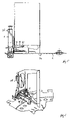
- FIG. 1 is a perspective view of a disclosed apparatus for dispensing fluids
- FIG. 2 is a perspective view of the apparatus in FIG. 1 with its internals partially exposed;
- FIGS. 3 to 6 are side views and perspective rear views of a pump-module of the apparatus in FIG. 1 and in accordance with the disclosure;
- FIG. 3A is a perspective view of a connector-counterpart used in the apparatus of FIG. 1 ;
- FIGS. 7 to 9 are a perspective side view and sectional front and side views of a receptacle in the apparatus in FIG. 1 and in accordance with the disclosure;
- FIGS. 10 to 12 are perspective views of three types of developer containers for use in the apparatus in FIG. 1 .
- FIGS. 1 and 2 illustrate an example of an apparatus 1 for dispensing a plurality of fluids, such as (components of) paints, paint colorants, hair dyes, shampoos, foundations, and the like. It can be used for dispensing numerous recipes of the said products and can be located e.g. at a retailer of decorative paints, a hairdresser, or a spa, respectively.
- a plurality of fluids such as (components of) paints, paint colorants, hair dyes, shampoos, foundations, and the like. It can be used for dispensing numerous recipes of the said products and can be located e.g. at a retailer of decorative paints, a hairdresser, or a spa, respectively.
- This particular dispensing apparatus 1 is an automated version and includes a horizontal turntable 2 (best shown in FIG. 7 ), with a plurality of metering pumps 3 and bag-in-box containers 4 mounted along its circumference.
- the turntable 2 can be rotated between discrete positions, e.g. thirty-two positions including a front or dispensing position (marked in FIG. 2 by a slightly raised container), about a vertical, central axis by means of a drive (not shown).
- the apparatus 1 includes a frame 5 of e.g. aluminium extrusion profiles on which sheets 6 of metal or a polymer (transparent, translucent or opaque) have been attached by means of e.g. screws.
- a control panel 7 comprising a display and a small keyboard for entering information, such as customer data and recipes, is mounted on the right hand side of the frame 5 , next to a door 8 .
- This door 8 contains a computer for storing the said information and for driving the turntable 2 , actuators for operating the pumps 3 , etc., and is further equipped with a handle 9 , a lock 10 , and a switch 11 for turning the apparatus 1 on or off.
- a weighing device 12 is positioned below the door 8 in a recess where a cup or the like for receiving fluids dispensed by the apparatus 1 can be placed.
- a substantially triangular hatch 13 is pivotally mounted, along one of its rims, in the top sheet 6 .
- the hatch 13 is locked in place by the upper rim of the door 8 .
- Opening the door 8 and the hatch 13 reveals a plurality of modules 14 (clearly shown in e.g. FIGS. 3 to 6 ), releasably mounted in a circle on the turntable 2 .
- each of the modules 14 comprises a guide member 15 of sheet metal or a synthetic material, which also serves as a frame on which inter alia one of the mentioned metering pumps 3 is mounted.
- Pumps 3 of this type are known in the art and comprise, at least in this example, a cylinder 16 , which communicates with one of the mentioned bag-in-box containers 4 (shown in FIGS. 2 , 3 , and 5 ).
- the pumps 3 further comprise a piston, mounted inside the cylinder 16 and provided with a piston rod 17 , which, on its upper end, is provided with a washer or flange 18 .
- the cylinders 16 are sufficiently large, i.e. enable a stroke of at least 20 ml, e.g. 30 ml.
- an actuator 19 on the inside of the door 8 engages the flange 18 of the pump 3 that is in the front position.
- the actuator 19 is shaped like a claw, which allows unobstructed horizontal movement of the pumps 3 , but engages, when it moves vertically, the flange 18 and hence the piston rod 17 and the piston of the respective pump 3 in front of it. Upward movement of the actuator 19 causes an intake stroke of the piston and downward causes a discharge stroke.
- the cylinder 16 is mounted in the top part of a pump housing 20 , containing a known valve member, e.g., a ball valve or a cylindrical valve, which can be operated by means of a lever 21 .
- a known valve member e.g., a ball valve or a cylindrical valve
- the cylinder 16 communicates, via a connector 22 , with a container 4 and can be filled with a desired amount of the fluid from the container 4 by moving the flange 18 upwards over a desired or predetermined length.
- the valve member can be rotated to a dispensing position. In this position, the cylinder 16 communicates with a dispensing opening in the bottom surface of the pump housing 20 and the fluid can be dispensed by moving the flange 18 downwards.
- the turntable 2 comprises along its circumference square recesses 23 for receiving the pump housings 20 , which recesses 23 are flanked on either side by threaded screw holes 24 .
- the turntable 2 is further provided with a ring of small holes 25 , which allow the turntable 2 to be rotated by means of one or more electric motors positioned beneath the turntable 2 and each provided with a wheel (not shown) comprising protrusions, which correspond in size and mutual distance to the said small holes 25 .
- drip holes 26 are provided, which are in register with small receptacles 27 that will be discussed in more detail below.
- radially extending slots 28 are provided as well as five relatively large holes in a circle, which serve to reduce the weight of the turntable 2 and hence of the apparatus 1 .
- each of the modules 14 comprises a guide member 15 , which also serves as a frame.
- the member 15 comprises a front wall 29 provided with a foot 30 extending horizontally and in forward direction.
- the foot 30 supports a pump housing 20 and is provided with two through holes.
- the guide member 15 further comprises a sidewall 31 and rear wall 32 , which together with the front wall 29 and the sidewall of an adjacent module 14 provide a guide for a container 4 .
- the sidewall 31 has an inclined upper rim, which facilitates inserting a container 4 , and a bent lower rim 33 , which carries a connector 22 and a receptacle 27 surrounding the connector 22 .
- the rear wall 32 of the module 14 comprises an extension 34 extending below the module 14 and beyond the rear wall 32 .
- a module 14 can be quickly secured to the turntable 2 by inserting the extension 34 in one of the slots 28 at an angle with the turntable 2 and, once the extension 34 has been inserted, rotating the module 14 downwards until the foot 30 rests on the turntable 2 and the through holes in the foot 30 and the pump housing 21 are in register with the threaded screw holes 24 in the turntable 2 .
- the module 14 can then be fastened to the turntable 2 by means of bolts 35 .
- the front portion of the modules 14 can also be fastened to the turntable with e.g. a clamping device, a sufficiently strong magnet, a snap-fit construction, through friction, etc.
- Each of the modules 14 is provided with an actuator, preferably a lever 36 made e.g. of metal or a synthetic material and mounted pivotably, by means of an axis 37 welded to the lever 36 and positioned between the front wall 29 of the module 14 and the receptacle 27 or snapped-fitted in recesses in the receptacle 27 , and extending parallel to a tangent of the turntable 2 .
- the lever 36 comprises a relatively long and substantially U-shaped operating handle 38 on one side of the pivot axis 37 and two relatively short parallel arms 39 on the other side of the pivot axis 37 extending at an angle of about 90 degrees with respect to the handle 38 .
- the arms 39 are provided with round protrusions 40 extending inwardly.
- Each of the bag-in-box containers 4 includes a connector-counterpart 41 ( FIG. 3A ), which is part of the bag and extends through and opening in the bottom wall of the box.
- the counterpart 41 includes two straight rails 42 extending parallel to each other and to the bottom wall of the box.
- the upper walls 43 of the rails 42 are longer than the lower walls 44 , such that, when a container 4 is placed in the guide member 15 while the handle 38 is in a forward position and the arms 39 consequently extend upwards, the upper walls 43 abut the protrusions 40 on the arms 39 .
- the arms 39 are pushed slightly downwards—and the handle 38 slightly upwards—and the protrusions 40 engage or are at least positioned over the lower walls 44 of the rails 42 .
- the counterpart 41 and the container 4 can be pulled downwards by simply pushing the handle 38 towards the module 14 until a secure fluid connection has been established.
- the container 4 can be removed by pulling the handle 38 away from the module 14 .
- the handle Upon establishing a fluid connection between the respective pump and the container, the handle extends substantially parallel to the pump and the container. I.e., a relatively long handle can be employed, yielding a relatively low operating force, without necessitating a more voluminous design of the apparatus 1 .
- the protrusion(s) can be provided with a friction reducing material, such as Teflon, or with a wheel or bearing.
- a friction reducing material such as Teflon
- the connector-counterpart was made of an injection moulded low friction material, viz. polyethylene.
- the apparatus shown in the figures comprises a weighing device 12 for measuring the weight of fluid dispensed by one or more of the pumps 3 .
- This device can inter alia be used to check whether the correct amounts of each of the components of a certain recipe that should have been dispensed were actually dispensed.
- the weighing device 12 in this example comprises a plate (shown in FIG. 1 and 2 on which a cup 12 ′ or the like (i.e., product container 12 ′) can be placed (see FIG. 2 ).
- the plate is mounted on a load-cell (hidden from view and known in itself), e.g. a slotted aluminium bar provided with one or more, e.g. four, strain gauges.
- the change in resistance of the strain gauges is measured and fed, via an amplifier, and optionally a low pass filter, into the computer in the door 8 of the apparatus and processed (e.g. filtered).
- an accurate measurement may require several seconds, during which interval the influence of vibrations in the apparatus itself or from external sources is filtered out.
- the time needed for dispensing a recipe can be reduced as follows.
- the computer stores information on the volumetric amounts that have been dispensed by the pumps 3 from each of the containers 4 and on the amount of fluid that, based on this volumetric information and the density of the respective fluid, should still be present in each of the containers 4 .
- this amount is above a suitable threshold value, e.g. 10% of the volume of a filled container, the weight measurements are carried out quickly and/or the turntable 2 is already rotated to its next position during measurement thus reducing the overall time needed to prepare a specific paint, hair dye, or the like.
- the dispensing process continues. If the result is outside this range and e.g. too little fluid has been dispensed, the turntable 2 returns to its previous position, a retry is executed, and/or the operator is warned. In such a case, a container 4 may have been installed incorrectly, resulting in an inadequate fluid connection, or the container 4 may have been depleted unexpectedly, and the container 4 should respectively be installed properly or replaced by a filled container 4 .
- the time used for weight measurements relating to that container is lengthened to an interval that is sufficient for a more accurate measurement. If it appears, based on this measurement, that the container 4 has been depleted, the operator is warned and the container 4 should be replaced by a filled container 4 .
- this system checks whether the correct amounts of fluid have been dispensed, there is no longer a need to replace the containers before they are effectively empty. In other words, the amount of fluid still present in a container when it is replaced, i.e. the amount of waste, can be reduced.
- the weighing device according to the present invention can also be used, e.g. during installation of the dispensing apparatus, to measure the density of the fluids and/or to calibrate the dispensing action of one or more, preferably all, of the pumps.
- this density can be determined by dispensing a pre-selected amount, e.g. equal to the amount obtained with one stroke of a piston pump, and accurately measuring the weight of the dispensed amount. Dividing the measured weight by the dispensed volume yields a value for density, which can be inputted in the above-mentioned computer.
- the apparatus according to the present invention can be calibrated by determining the smallest amount of fluid that is likely to be dispensed, e.g. 0.1 ml, and repeatedly, preferably from three to eight times, dispensing an amount slightly smaller than the determined amount, e.g. 0.8 ml, and weighing the dispensed amounts. This procedure is preferably followed by, repeatedly, again preferably from three to eight times, dispensing an amount e.g. two or three times larger than the previous amount, i.e.
- the pumps can be driven accurately, even in a volume range where the pumps exhibit non-linear behaviour, by means of the said matrix or table preferably supplemented with linear interpolation to calculate values in between the mean values.
- Each of the connectors 22 is surrounded by a receptacle 27 shaped as a funnel.
- the opening in the bottom of each of the receptacles 27 extends through one of the above-mentioned drip holes 26 in the turntable 2 .
- a shared receptacle depicted in FIGS. 7 to 9 , is positioned beneath the said receptacles 27 to collect fluid dripping from these receptacles 27 .
- the shared receptacle comprises an inclined first plate 45 made of sheet metal or a synthetic material, e.g. ABS, and positioned beneath a number of the said receptacles 27 , in this example beneath roughly 50 percent of the receptacles 27 .
- the first plate 45 includes a bent raised edge 46 along it lower rim.
- Inclined second plates 47 also made of sheet metal or a synthetic material and also including a bent raised edge 48 along respective lower rims, are positioned beneath each of the ends of the raised edge 46 of the first plate 45 and beneath further receptacles.
- a drawer 49 also made of sheet metal or a synthetic material, is positioned beneath the lower ends of the raised edges 48 of the second plates 47 .
- first and second plates 45 , 47 , and the drawer 49 together provide an effective common receptacle, which follows the circumference of the turntable 2 such that fluid dripping from any one of the receptacles 27 will be collected by at least one of the said plates 45 , 47 , and eventually the drawer 49 .
- a base paint or specific colorants make up a larger part of most common recipes than others.
- a developer is a component of most recipes and, consequently, larger amounts of such a developer are required.
- One variant of the present dispensing apparatus shown in FIG. 10 , comprises dedicated containers 50 of a blow moulded synthetic material or made of thin sheet metal, e.g. stainless steel, for the said developer.
- Each of these containers 50 is in fluid connection with an additional container 51 positioned towards the centre of the turntable 2 .
- the containers 50 , 51 function as communicating vessels by means of a duct 52 connecting the bottom walls of these containers 50 , 51 .
- a further variant, shown in FIG. 11 comprises a number of larger containers 50 , in this example four larger containers 50 , each having a rear portion 53 extending beyond the rear walls of the other containers 4 and comprising two tapering walls and a partially circular wall 54 spanning a quarter of a circle.
- the rear portions 53 of the larger containers 50 are thus complementary in shape with respect to each other and with respect to the other containers 4 and take up substantially all of the space defined by the rear portions of the other containers and provide almost maximum additional fluid holding capacity.
- a filler opening, closed by means of a screw cap 55 is provided in a front portion of each of the containers 50 .
- each of the containers 50 can be used for one specific percentage, e.g. 3, 6, 9, and 12 percent, or 18 percent in two diametrically opposed containers and 0 percent (for dilution) in the other two diametrically opposed containers.
- a still further variant, shown in FIG. 12 differs from the variant shown in FIG. 11 primarily in that the front and rear portions of the container 50 are connected halfway the partially circular wall 54 .
- the containers 50 are located at, in this case, four positions 90 degrees apart. During filling, only one of the containers 50 can be in the front position and only the filler opening of the container 50 in the front position is accessible. Thus, the chance of filling the containers 50 with a wrong fluid, e.g. a wrong strength of peroxide, is reduced.
- the apparatus according to the present invention can be configured as a linear dispensing apparatus i.e. with the containers aligned is a row.
Abstract
Description
Claims (46)
Priority Applications (11)
| Application Number | Priority Date | Filing Date | Title |
|---|---|---|---|
| US10/694,485 US7347344B2 (en) | 2003-10-27 | 2003-10-27 | Apparatus for dispensing a plurality of fluids and container for use in the same |
| CA2543813A CA2543813C (en) | 2003-10-27 | 2004-10-26 | Apparatus for dispensing a plurality of fluids and container for use in the same |
| AT04791312T ATE388756T1 (en) | 2003-10-27 | 2004-10-26 | DEVICE FOR DISPENSING MULTIPLE FLUIDS AND CONTAINER FOR USE THEREIN |
| ES04791312T ES2303106T3 (en) | 2003-10-27 | 2004-10-26 | APPARATUS FOR DISPENSING A PLURALITY OF FLUIDS AND CONTAINER FOR USE IN THE SAME. |
| CNB2004800370041A CN100475322C (en) | 2003-10-27 | 2004-10-26 | Apparatus for dispensing a plurality of fluids and container for use in the same |
| EP04791312A EP1684892B1 (en) | 2003-10-27 | 2004-10-26 | Apparatus for dispensing a plurality of fluids and container for use in the same |
| PCT/EP2004/052664 WO2005039747A2 (en) | 2003-10-27 | 2004-10-26 | Apparatus for dispensing a plurality of fluids and container for use in the same |
| JP2006537293A JP4768623B2 (en) | 2003-10-27 | 2004-10-26 | Dispensing device for multiple fluids and container for use in the device |
| AU2004283491A AU2004283491B2 (en) | 2003-10-27 | 2004-10-26 | Apparatus for dispensing a plurality of fluids and container for use in the same |
| DE602004012437T DE602004012437T2 (en) | 2003-10-27 | 2004-10-26 | DEVICE FOR DISTRIBUTING MULTIPLE FLUIDS AND CONTAINERS FOR USE THEREIN |
| US11/551,371 US7360564B2 (en) | 2003-10-27 | 2006-10-20 | Apparatus for dispensing a plurality of fluids and container for use in the same |
Applications Claiming Priority (1)
| Application Number | Priority Date | Filing Date | Title |
|---|---|---|---|
| US10/694,485 US7347344B2 (en) | 2003-10-27 | 2003-10-27 | Apparatus for dispensing a plurality of fluids and container for use in the same |
Related Child Applications (1)
| Application Number | Title | Priority Date | Filing Date |
|---|---|---|---|
| US11/551,371 Division US7360564B2 (en) | 2003-10-27 | 2006-10-20 | Apparatus for dispensing a plurality of fluids and container for use in the same |
Publications (2)
| Publication Number | Publication Date |
|---|---|
| US20050087545A1 US20050087545A1 (en) | 2005-04-28 |
| US7347344B2 true US7347344B2 (en) | 2008-03-25 |
Family
ID=34522614
Family Applications (2)
| Application Number | Title | Priority Date | Filing Date |
|---|---|---|---|
| US10/694,485 Expired - Fee Related US7347344B2 (en) | 2003-10-27 | 2003-10-27 | Apparatus for dispensing a plurality of fluids and container for use in the same |
| US11/551,371 Expired - Fee Related US7360564B2 (en) | 2003-10-27 | 2006-10-20 | Apparatus for dispensing a plurality of fluids and container for use in the same |
Family Applications After (1)
| Application Number | Title | Priority Date | Filing Date |
|---|---|---|---|
| US11/551,371 Expired - Fee Related US7360564B2 (en) | 2003-10-27 | 2006-10-20 | Apparatus for dispensing a plurality of fluids and container for use in the same |
Country Status (10)
| Country | Link |
|---|---|
| US (2) | US7347344B2 (en) |
| EP (1) | EP1684892B1 (en) |
| JP (1) | JP4768623B2 (en) |
| CN (1) | CN100475322C (en) |
| AT (1) | ATE388756T1 (en) |
| AU (1) | AU2004283491B2 (en) |
| CA (1) | CA2543813C (en) |
| DE (1) | DE602004012437T2 (en) |
| ES (1) | ES2303106T3 (en) |
| WO (1) | WO2005039747A2 (en) |
Cited By (33)
| Publication number | Priority date | Publication date | Assignee | Title |
|---|---|---|---|---|
| US20060169718A1 (en) * | 2004-02-27 | 2006-08-03 | Eric Buining | Fluid and hair-dye dispensers |
| US20060261090A1 (en) * | 2004-02-27 | 2006-11-23 | Lenteq, Lp | Fluid and hair dye dispensers having central support column |
| US20070056989A1 (en) * | 2000-07-19 | 2007-03-15 | Peter Adema | Hair dye having larger centered containers |
| US20070212468A1 (en) * | 2006-03-06 | 2007-09-13 | The Coca-Cola Company | Methods and Apparatuses for Making Compositions Comprising an Acid and an Acid Degradable Component and/or Compositions Comprising a Plurality of Selectable Components |
| US20070267441A1 (en) * | 2006-03-06 | 2007-11-22 | The Coca-Cola Company | Dispenser for Beverages Including Juices |
| US20080271809A1 (en) * | 2007-03-15 | 2008-11-06 | The Coca-Cola Company | Multiple Stream Filling System |
| US20090069932A1 (en) * | 2007-09-06 | 2009-03-12 | The Coca-Cola Company | Method and Apparatuses for Providing a Selectable Beverage |
| US20090223997A1 (en) * | 2003-03-21 | 2009-09-10 | Gfi Innovations, Inc. | Methodology and Apparatus for Storing and Dispensing Liquid Components to Create Custom Formulations |
| US20100181340A1 (en) * | 2009-01-17 | 2010-07-22 | Mandolyn Wallace | System and method for creating and dispensing hair color |
| US20110204088A1 (en) * | 2008-11-10 | 2011-08-25 | Mettler-Toledo Ag | Dosage-dispensing device with a changing mechanism for dosage-dispensing units |
| US8162181B2 (en) | 2006-03-06 | 2012-04-24 | The Coca-Cola Company | Beverage dispensing system |
| US20120175383A1 (en) * | 2011-01-07 | 2012-07-12 | Fluid Management Operations, Llc | Apparatus for Dispensing a Plurality of Fluids |
| US20120245730A1 (en) * | 2010-11-02 | 2012-09-27 | Yuchen Zhou | Specimen dispensing device |
| US8386072B1 (en) * | 2009-04-20 | 2013-02-26 | Pneumatic Scale Corporation | Dual meter filler apparatus and method |
| US20130074982A1 (en) * | 2011-09-28 | 2013-03-28 | Gfi Innovations, Inc. | Methodology and Apparatus for Storing and Dispensing Liquid Components to Create Custom Formulations |
| US20130233881A1 (en) * | 2008-06-20 | 2013-09-12 | Fillon Technologies, Societe Par Actions Simplifiee (S.A.S.) | Device for storing, selecting, and metering base colors for painting, particularly automobile painting |
| US20130276411A1 (en) * | 2010-09-24 | 2013-10-24 | Gian Luca Casadio Prati | Vending machine, particularly for cold drinks |
| US20130277394A1 (en) * | 2012-04-18 | 2013-10-24 | Schroeder Industries, Inc. D/B/A Schroeder America | Moveable roll around self-contained ice cooled beverage dispensing apparatus |
| US8739840B2 (en) | 2010-04-26 | 2014-06-03 | The Coca-Cola Company | Method for managing orders and dispensing beverages |
| US8757222B2 (en) | 2010-04-26 | 2014-06-24 | The Coca-Cola Company | Vessel activated beverage dispenser |
| US20140196221A1 (en) * | 2013-01-14 | 2014-07-17 | Stephen D'Amico | Hair Color (or Dye) Storage, Dispensing and Measurement (or Measuring) System |
| US8851329B2 (en) | 2007-09-06 | 2014-10-07 | The Coca-Cola Company | Systems and methods of selecting and dispensing products |
| US20160194186A1 (en) * | 2013-09-05 | 2016-07-07 | Squell Produktion Und Handel Gmbh | Tapping device for a bag-in-box package and actuating apparatus and cartridge therefor |
| US9394153B2 (en) | 2007-03-15 | 2016-07-19 | The Coca-Cola Company | Multiple stream filling system |
| US9415992B2 (en) | 2006-03-06 | 2016-08-16 | The Coca-Cola Company | Dispenser for beverages having a rotary micro-ingredient combination chamber |
| US9821992B2 (en) | 2006-03-06 | 2017-11-21 | The Coca-Cola Company | Juice dispensing system |
| US9865023B2 (en) | 2008-02-04 | 2018-01-09 | The Coca-Cola Company | Methods of creating customized beverage products |
| US10280060B2 (en) | 2006-03-06 | 2019-05-07 | The Coca-Cola Company | Dispenser for beverages having an ingredient mixing module |
| US10287040B2 (en) | 2017-07-31 | 2019-05-14 | Alpha Brewing Operations | Material saving canning system |
| US20210008293A1 (en) * | 2018-03-09 | 2021-01-14 | Unither Pharmaceuticals | Device for preparing a dose of medicament on demand |
| US20220055887A1 (en) * | 2019-03-11 | 2022-02-24 | Fillon Technologies | Machine for distributing a liquid or pasty product |
| US11370652B1 (en) * | 2018-07-24 | 2022-06-28 | Richard James DeMartini | Method and system for blending and dispensing liquid cannabis |
| US11535409B1 (en) * | 2019-12-18 | 2022-12-27 | Richard James DeMartini | Personal liquid cannabis 6D oil printer and smart cartridges |
Families Citing this family (54)
| Publication number | Priority date | Publication date | Assignee | Title |
|---|---|---|---|---|
| US7347344B2 (en) | 2003-10-27 | 2008-03-25 | Fluid Management Operation Llc | Apparatus for dispensing a plurality of fluids and container for use in the same |
| US7320416B2 (en) * | 2005-04-26 | 2008-01-22 | Fluid Management Operations Llc | Shelving systems and holders for flexible bags for containing fluid for use in fluid dispensing systems |
| US7690405B2 (en) * | 2005-07-18 | 2010-04-06 | Fluid Management, Inc. | Multiple fluid dispenser |
| US7527078B2 (en) | 2005-10-13 | 2009-05-05 | Fluid Management, Llc | Apparatuses for dispensing materials volumetrically and gravimetrically based on a stored formula and methods of dispensing formulas using the same |
| WO2007048069A2 (en) | 2005-10-21 | 2007-04-26 | Action Wobble Inc. | Action wobble spring mounting assembly and method of manufacture |
| US20100129524A1 (en) * | 2006-01-20 | 2010-05-27 | Steven Sternberger | Methods of dispensing powder coating compositions and articles coated therewith |
| US20070276677A1 (en) * | 2006-05-05 | 2007-11-29 | Liquid Mist, Inc. | Method and apparatus for dispensing tanning lotions at the point of sale |
| US7967037B2 (en) * | 2007-06-14 | 2011-06-28 | Calgary Scale Services (1988) Ltd. | Apparatus and system for dispensing liquids |
| US7963303B2 (en) * | 2008-03-03 | 2011-06-21 | The Saranow Group, Llc | Manual hair dye apparatus and method for using the same |
| US8336582B2 (en) | 2008-03-03 | 2012-12-25 | Saranow Mitchell H | Method and system for the preparation of hair dye colors |
| US8897915B2 (en) | 2008-03-03 | 2014-11-25 | SureTint Technologies, LLC | Inventory security management for a hair dye storage system |
| US9414665B2 (en) | 2008-03-03 | 2016-08-16 | SureTint Technologies, LLC | Blending color and control management system |
| US11235298B2 (en) | 2008-03-03 | 2022-02-01 | SureTint Technologies, LLC | Blending station apparatus and method for using the same |
| US8567455B2 (en) | 2008-03-03 | 2013-10-29 | SureTint Technologies, LLC | Blending station apparatus and method for using the same |
| US11246395B2 (en) | 2008-03-03 | 2022-02-15 | SureTint Technologies, LLC | Color conversion system and method |
| US9177339B2 (en) | 2008-03-03 | 2015-11-03 | Sure Tint Technologies, LLC | System and method for color preparation and management |
| US9149108B2 (en) | 2011-02-24 | 2015-10-06 | SureTint Technologies, LLC | System and method for batch sizing hair dye mixtures |
| US8393363B2 (en) * | 2008-03-03 | 2013-03-12 | SureTint Technologies, LLC | Blending station apparatus and method for using the same |
| ATE547169T1 (en) * | 2008-07-16 | 2012-03-15 | Fillon Technologies | DEVICE FOR STORING, SELECTING AND DISTRIBUTING A RANGE OF PRODUCTS, IN PARTICULAR A RANGE OF BASE COLORS FOR CAR PAINTS |
| FR2938999B1 (en) * | 2008-11-24 | 2011-07-01 | Oreal | METHOD OF PREPARING A FRAGRANCE WITHIN A SYSTEM COMPRISING A PLURALITY OF INTERACTIVE PERFUME FORMULATION TERMINALS AND A AGENCY SERVER FOR EXCHANGING DATA WITH THE PLURALITY OF TERMINALS |
| EP2198950B1 (en) * | 2008-12-19 | 2011-10-12 | Fluid Management Operations LLC | Apparatus for dispensing a plurality of fluids |
| IT1393787B1 (en) * | 2009-03-30 | 2012-05-08 | Cps Color Equipment Spa | DISPENSE DEVICE FOR FLUID PRODUCTS AND ITS RELATION PROCEDURE |
| CN102666305A (en) * | 2009-06-30 | 2012-09-12 | 肖勒公司 | Bag in box packaging having a locating panel for a tap |
| WO2011123503A1 (en) | 2010-04-01 | 2011-10-06 | B & H Manufacturing Company, Inc. | Extrusion application system |
| KR101233092B1 (en) * | 2010-09-17 | 2013-02-14 | 이호 | Spice feeding apparatus of food-making system using internet |
| GB201101075D0 (en) | 2011-01-21 | 2011-03-09 | Labminds Ltd | Automated solution dispenser |
| IT1403834B1 (en) * | 2011-02-03 | 2013-10-31 | Cps Color Equipment Spa | DISPENSE EQUIPMENT FOR FLUID PRODUCTS |
| US10143984B2 (en) | 2011-03-28 | 2018-12-04 | Fast & Fluid Management B.V. | Method and apparatus for dispensing liquids from a plurality of cartridges |
| US8813793B2 (en) * | 2011-08-02 | 2014-08-26 | Dedoes Industries, Inc. | Paint formulation and dispensing apparatus |
| US8936390B2 (en) * | 2011-12-16 | 2015-01-20 | Microblend Technologies, Inc. | Method and apparatus for producing paint |
| EP2874736B1 (en) | 2012-07-18 | 2023-04-19 | accroma labtec Ltd. | Automated solution dispenser |
| FR3003241B1 (en) * | 2013-03-14 | 2016-02-12 | Vuitton Louis Sa | RECHARGEABLE DEVICE FOR PACKAGING AND DISPENSING A FLUID PRODUCT |
| US9469463B2 (en) * | 2013-08-29 | 2016-10-18 | Tastetro, Inc. | Automated dispenser and method for dispensing |
| US9591943B2 (en) * | 2013-08-29 | 2017-03-14 | Tastetro Inc. | Automated dispenser and method for dispensing |
| US10077764B2 (en) * | 2014-02-20 | 2018-09-18 | Stephen B. Maguire | Cart and method for dispensing liquid color |
| CA2965597A1 (en) * | 2014-10-28 | 2016-05-06 | Luca Drocco | Openable tintometric machine |
| US10124304B2 (en) * | 2014-10-28 | 2018-11-13 | Luca Drocco | Assembly of a tintometric machine and a trolley |
| US9393536B2 (en) * | 2014-11-20 | 2016-07-19 | Dedoes Industries, Inc. | Paint dispensing apparatus |
| JP2018507103A (en) | 2015-02-06 | 2018-03-15 | ラブマインズ リミテッド | Automated solution dispenser |
| FR3048170B1 (en) * | 2016-02-25 | 2018-04-13 | Kuantom | APPARATUS FOR MAKING A BEVERAGE |
| US10399840B2 (en) | 2016-04-19 | 2019-09-03 | Pepsico, Inc. | Beverage dispensing valve system |
| EP3318318A1 (en) * | 2016-11-04 | 2018-05-09 | Fast&Fluid Management B.V. | Dispensing apparatus and releasably connectable fluid container for use in such dispensing apparatus |
| CN109296362B (en) * | 2018-08-31 | 2022-03-01 | 中国石油天然气股份有限公司 | Rotary sand filling device, rotary sand filling system applied to sand filling model and rotary sand filling method applied to sand filling model |
| US20210252465A1 (en) * | 2018-09-17 | 2021-08-19 | Zhengzhou Sanhua Technology & Industry Co., Ltd. | Weight-volume mixing color matching method, reclamation mechanism and automatic color mixer for automobile refinishing paintings |
| UA130947U (en) * | 2018-10-16 | 2018-12-26 | Роман Вікторович Жалінській | DEVICES FOR DOSING LOW VOLUMES OF LIQUID |
| JP2022513121A (en) * | 2018-11-20 | 2022-02-07 | エルジー・ファルーク・カンパニー | Hair dye dispenser and hair dye providing system including this |
| US11529597B2 (en) * | 2019-01-31 | 2022-12-20 | Zhengzhou Sanhua Technology & Industry Co., Ltd. | Turntable color machine |
| WO2020165928A2 (en) * | 2019-02-12 | 2020-08-20 | Corob S.P.A. | Machine and method to automatically dispense fluid products, in particular liquid dyes |
| JP2020163715A (en) * | 2019-03-29 | 2020-10-08 | ブラザー工業株式会社 | Liquid consumption device |
| IT201900008331A1 (en) * | 2019-06-07 | 2020-12-07 | Dromont S P A | DOSING MACHINE FOR THE DISPENSING OF DOSED QUANTITIES OF FLUID PRODUCTS, IN PARTICULAR FOR THE PREPARATION OF PAINTS, VARNISHES, DYES AND SIMILAR, AND DISPOSABLE CARTRIDGE FOR A DOSING MACHINE |
| US10897979B1 (en) | 2019-09-12 | 2021-01-26 | SureTint Technologies, LLC | System and method for hair dye color conversion |
| KR20210115275A (en) * | 2020-03-12 | 2021-09-27 | 엘지파루크 주식회사 | Dispenser |
| BR102021011665A2 (en) * | 2021-06-16 | 2022-12-27 | Leandro Agostini | AUTOMATIC DOSING SYSTEM FOR LIQUID SAMPLES |
| WO2023141598A2 (en) * | 2022-01-21 | 2023-07-27 | Yuv Beauty, Inc. | Apparatus for connected hair pigment dispenser |
Citations (65)
| Publication number | Priority date | Publication date | Assignee | Title |
|---|---|---|---|---|
| US2630259A (en) * | 1949-04-23 | 1953-03-03 | Edward M Stein | Method and means for dispensing beverages |
| US2923438A (en) | 1958-06-09 | 1960-02-02 | Martin Senour Company | Automatic paint manufacturing machine |
| US3074597A (en) | 1958-11-21 | 1963-01-22 | Microdot Inc | Pigment measuring and dispensing device |
| US4259372A (en) | 1978-07-13 | 1981-03-31 | Phillips Petroleum Company | Method and apparatus for applying sealant to a seam in a container |
| US4473173A (en) | 1983-01-10 | 1984-09-25 | Applied Color Systems, Inc. | Apparatus and method for low volume dispensing |
| US4781312A (en) | 1986-07-03 | 1988-11-01 | Strazdins (International) Pty. Limited | Liquid dispenser |
| US4871262A (en) | 1988-02-04 | 1989-10-03 | Hydrocosmetics, Inc. | Cosmetic dispensing system |
| US4928853A (en) * | 1988-08-19 | 1990-05-29 | Fountain Fresh, Inc. | End aisle fluid mixing and dispensing system |
| US4964534A (en) | 1987-06-24 | 1990-10-23 | Strazdins (International) Pty. Limited | Double piston colorant dispenser |
| US5083591A (en) | 1989-11-06 | 1992-01-28 | Dunn Edwards, Corp., & Fluid Management Ltd. Part. | Process for dispensing liquid colorants into a paint can, and quality control therefor |
| US5163010A (en) | 1990-02-22 | 1992-11-10 | Revlon Consumer Products Corporation | Formulating device for cosmetically functional cosmetic products |
| US5240502A (en) | 1990-11-13 | 1993-08-31 | Mactron, Inc. | Improvement in apparatus for applying a coating to a moving surface |
| US5311293A (en) | 1983-07-18 | 1994-05-10 | Chromatics Color Sciences International, Inc. | Method and instrument for selecting personal compatible colors |
| US5478238A (en) | 1993-08-03 | 1995-12-26 | Parfums Christian Dior | Method and apparatus for determining the foundation makeup color that substantially reproduces a person's natural skin color |
| US5495338A (en) | 1992-05-06 | 1996-02-27 | Parfums Christian Dior | Process for making up the face, particularly the eyes, and device for carrying it out |
| US5622692A (en) | 1993-08-23 | 1997-04-22 | Elizabeth Arden Company, Division Of Conopco, Inc. | Method and apparatus for customizing facial foundation products |
| US5624056A (en) | 1995-05-19 | 1997-04-29 | Automatic Bar Controls, Inc. | Condiment dispensing system |
| EP0843163A1 (en) | 1996-09-25 | 1998-05-20 | Ching Fu Kuan | Automatic liquid material metering system |
| US5780018A (en) | 1991-06-21 | 1998-07-14 | The Boots Company Plc | Cosmetic formulations |
| US5785960A (en) | 1997-03-19 | 1998-07-28 | Elizabeth Arden Co., Division Of Conopco, Inc. | Method and system for customizing dermatological foundation products |
| US5855626A (en) | 1996-02-06 | 1999-01-05 | Britsol-Myers Squibb Company | Method for mixing and dispensing oxygen degradable hair dye concentrates |
| US5903465A (en) | 1993-08-23 | 1999-05-11 | Elizabeth Arden Company | Method and apparatus for customizing cosmetic products |
| US5950874A (en) | 1996-02-09 | 1999-09-14 | Italtinto S.R.L. | Batching machine, in particular for dyes |
| US5992691A (en) | 1997-07-07 | 1999-11-30 | Fluid Management | Dispensing apparatus for fluid contained in flexible packages |
| US6024250A (en) | 1998-01-26 | 2000-02-15 | Hickey; Patrick J. | Tip sealing system for non-contact glue applicator |
| US6067504A (en) | 1983-07-18 | 2000-05-23 | Chromatics Color Sciences International, Inc. | Method for correctly identifying hair color |
| US6089408A (en) | 1998-03-27 | 2000-07-18 | Fox; Terry S. | Revolving hair coloring chemical dispenser |
| US6164497A (en) | 1999-07-27 | 2000-12-26 | H.E.R.O. Industries, A Division Of Middlefield Bancorp Limited | Paint colorant dispenser with notched gauge rod |
| US6177093B1 (en) | 1999-03-17 | 2001-01-23 | Color Access, Inc. | Method and system for color customizing cosmetic mass products |
| US6178341B1 (en) | 1997-12-18 | 2001-01-23 | Chromatics Color Sciences International, Inc. | Color measurement system with color index for skin, teeth, hair and material substances |
| EP1090679A1 (en) | 1998-10-07 | 2001-04-11 | Fluid Management | Apparatus for dispensing viscous fluids |
| US6269978B1 (en) * | 1999-07-16 | 2001-08-07 | Italtinto S.R.L. | Dispensing and dosing machine for dyestuffs |
| US6273298B1 (en) | 2000-03-08 | 2001-08-14 | Fluid Management, Inc. | Apparatus for dispensing viscous fluids from flexible packages and holder for such packages |
| US6284228B1 (en) | 1999-05-04 | 2001-09-04 | Dan Markowitz | Color blending system for foundation makeup compositions |
| WO2001075586A1 (en) | 2000-03-31 | 2001-10-11 | Imx Labs, Inc. | Nail polish color selection system and method |
| EP1167930A1 (en) | 2000-06-26 | 2002-01-02 | Hugo Hu | Automated precision liquid metering apparatus using injectors as metering devices |
| US6338349B1 (en) | 1998-12-18 | 2002-01-15 | L'oreal | Method and system for providing customized color cosmetics |
| US6402364B1 (en) | 1999-04-02 | 2002-06-11 | L'oreal | Portable dispenser for packaging and dispensing colored cosmetics |
| US20020081341A1 (en) | 2000-08-31 | 2002-06-27 | Cheryl Sott | Method, apparatus, and system for customizing essential oil formulations |
| US20020082745A1 (en) | 2000-01-31 | 2002-06-27 | Collaborative Technologies, Inc. | Method and system for producing customized cosmetic and pharmaceutical formulations on demand |
| US6412658B1 (en) | 2001-06-01 | 2002-07-02 | Imx Labs, Inc. | Point-of-sale body powder dispensing system |
| US20020091596A1 (en) | 2000-04-25 | 2002-07-11 | Dudek David Robert | Process and system for the customisation of consumer products |
| EP0800858B1 (en) | 1996-01-22 | 2002-07-17 | Fluid Management, Inc. | Paint dispensing apparatus |
| US20020095309A1 (en) | 2000-12-05 | 2002-07-18 | Joanna Rothschild | System and method for dispensing cosmetics products |
| USD461080S1 (en) | 2001-06-01 | 2002-08-06 | Imx Labs, Inc. | Cosmetic dispenser |
| US6437866B1 (en) | 1999-07-07 | 2002-08-20 | Fd Management, Inc. | System for assisting customers in selecting an optimum color cosmetic product |
| US20020131985A1 (en) | 2000-08-25 | 2002-09-19 | Unilever Home & Personal Care Usa, Division Of Conopco, Inc. | System for customizing personal care products |
| US20020130442A1 (en) | 2000-08-09 | 2002-09-19 | Elizabeth Arden Company, Division Of Conopco, Inc. | Lipstick machine |
| US6478235B1 (en) | 1999-03-03 | 2002-11-12 | Soederstroem Per | Device for the cleaning of a liquor spray nozzle assembly of a soda recovery boiler |
| USD465810S1 (en) | 2001-06-01 | 2002-11-19 | Imx Labs, Inc. | Cosmetic dispenser |
| EP1260435A1 (en) | 1997-02-21 | 2002-11-27 | The Geon Company | System and apparatus for dispensing high viscosity pigments |
| US20020194021A1 (en) | 2001-03-26 | 2002-12-19 | Mitsuo Matsumoto | Method for preparing and selling liquid cosmetics in a custom-made manner |
| US6502583B1 (en) | 1997-03-06 | 2003-01-07 | Drdc Limited | Method of correcting face image, makeup simulation method, makeup method makeup supporting device and foundation transfer film |
| US6510366B1 (en) | 1999-04-23 | 2003-01-21 | Elizabeth Arden Company, Division Of Conopco, Inc. | Apparatus and method for customizing cosmetic products |
| US6516245B1 (en) | 2000-05-31 | 2003-02-04 | The Procter & Gamble Company | Method for providing personalized cosmetics |
| US20030060925A1 (en) | 2001-09-24 | 2003-03-27 | Imx Labs, Inc. | Apparatus and method for custom comsmetic dispensing |
| US20030062379A1 (en) | 2001-09-24 | 2003-04-03 | Imx Labs, Inc. | Apparatus and method for custom cosmetic dispensing |
| WO2003031280A1 (en) | 2001-10-11 | 2003-04-17 | Itsac N.V. | Plastic spout |
| WO2003031161A1 (en) | 2001-10-08 | 2003-04-17 | Itsac N.V. | Assembly for a closable fluid connection |
| US20030090176A1 (en) | 2001-10-22 | 2003-05-15 | Imx Labs, Inc. | Point of sale cosmetic station |
| US6571003B1 (en) | 1999-06-14 | 2003-05-27 | The Procter & Gamble Company | Skin imaging and analysis systems and methods |
| US20030120534A1 (en) | 2001-12-21 | 2003-06-26 | Daniela Giacchetti | Cosmetic affinity indexing |
| WO2003083334A1 (en) | 2002-04-01 | 2003-10-09 | Fluid Management, Inc. | Valve assembly |
| USD485310S1 (en) | 2002-03-22 | 2004-01-13 | Imx Labs, Inc. | Cosmetic dispenser |
| WO2005039747A2 (en) | 2003-10-27 | 2005-05-06 | Fluid Management, Inc. | Apparatus for dispensing a plurality of fluids and container for use in the same |
Family Cites Families (7)
| Publication number | Priority date | Publication date | Assignee | Title |
|---|---|---|---|---|
| US5857589A (en) * | 1996-11-20 | 1999-01-12 | Fluid Research Corporation | Method and apparatus for accurately dispensing liquids and solids |
| DE69913967T2 (en) * | 1998-10-07 | 2004-10-21 | Fluid Man Wheeling | Dispenser for viscous liquids |
| US6637471B2 (en) * | 2001-06-05 | 2003-10-28 | Gfi Innovations, Inc. | Precision dispensing |
| US6457496B1 (en) * | 2001-07-10 | 2002-10-01 | Copower Technology Co., Ltd. | Liquid dispensing and metering system |
| GB0118085D0 (en) * | 2001-07-25 | 2001-09-19 | Ici Plc | Tinting machine for coating compositions, especially paints |
| US6863913B1 (en) * | 2001-11-09 | 2005-03-08 | Spee-Dee Packaging Machinery, Inc. | Food preparation process using bulk density feedback |
| US6742549B1 (en) * | 2003-01-21 | 2004-06-01 | Fqubed | Method and apparatus for quasi-continuous and quasi-simultaneous dispensing |
-
2003
- 2003-10-27 US US10/694,485 patent/US7347344B2/en not_active Expired - Fee Related
-
2004
- 2004-10-26 AU AU2004283491A patent/AU2004283491B2/en not_active Ceased
- 2004-10-26 CA CA2543813A patent/CA2543813C/en not_active Expired - Fee Related
- 2004-10-26 WO PCT/EP2004/052664 patent/WO2005039747A2/en active IP Right Grant
- 2004-10-26 AT AT04791312T patent/ATE388756T1/en not_active IP Right Cessation
- 2004-10-26 CN CNB2004800370041A patent/CN100475322C/en not_active Expired - Fee Related
- 2004-10-26 DE DE602004012437T patent/DE602004012437T2/en active Active
- 2004-10-26 JP JP2006537293A patent/JP4768623B2/en not_active Expired - Fee Related
- 2004-10-26 ES ES04791312T patent/ES2303106T3/en active Active
- 2004-10-26 EP EP04791312A patent/EP1684892B1/en not_active Not-in-force
-
2006
- 2006-10-20 US US11/551,371 patent/US7360564B2/en not_active Expired - Fee Related
Patent Citations (86)
| Publication number | Priority date | Publication date | Assignee | Title |
|---|---|---|---|---|
| US2630259A (en) * | 1949-04-23 | 1953-03-03 | Edward M Stein | Method and means for dispensing beverages |
| US2923438A (en) | 1958-06-09 | 1960-02-02 | Martin Senour Company | Automatic paint manufacturing machine |
| US3074597A (en) | 1958-11-21 | 1963-01-22 | Microdot Inc | Pigment measuring and dispensing device |
| US4259372A (en) | 1978-07-13 | 1981-03-31 | Phillips Petroleum Company | Method and apparatus for applying sealant to a seam in a container |
| US4473173A (en) | 1983-01-10 | 1984-09-25 | Applied Color Systems, Inc. | Apparatus and method for low volume dispensing |
| US6067504A (en) | 1983-07-18 | 2000-05-23 | Chromatics Color Sciences International, Inc. | Method for correctly identifying hair color |
| US6330341B1 (en) | 1983-07-18 | 2001-12-11 | Chromatics Color Sciences International, Inc. | Method and apparatus for hair color characterization and treatment |
| US5311293A (en) | 1983-07-18 | 1994-05-10 | Chromatics Color Sciences International, Inc. | Method and instrument for selecting personal compatible colors |
| US5313267A (en) | 1983-07-18 | 1994-05-17 | Chromatics Color Sciences International Inc. | Method and instrument for selecting personal compatible colors |
| US6314372B1 (en) | 1983-07-18 | 2001-11-06 | Chromatics Color Sciences International, Inc. | Method and apparatus for hair color characterization and treatment |
| US4781312A (en) | 1986-07-03 | 1988-11-01 | Strazdins (International) Pty. Limited | Liquid dispenser |
| US4964534A (en) | 1987-06-24 | 1990-10-23 | Strazdins (International) Pty. Limited | Double piston colorant dispenser |
| US4966308A (en) | 1987-06-24 | 1990-10-30 | Strazdins (International) Pty. Limited | Double piston colorant dispenser |
| US4871262A (en) | 1988-02-04 | 1989-10-03 | Hydrocosmetics, Inc. | Cosmetic dispensing system |
| US4928853A (en) * | 1988-08-19 | 1990-05-29 | Fountain Fresh, Inc. | End aisle fluid mixing and dispensing system |
| US5083591A (en) | 1989-11-06 | 1992-01-28 | Dunn Edwards, Corp., & Fluid Management Ltd. Part. | Process for dispensing liquid colorants into a paint can, and quality control therefor |
| US5163010A (en) | 1990-02-22 | 1992-11-10 | Revlon Consumer Products Corporation | Formulating device for cosmetically functional cosmetic products |
| US5240502A (en) | 1990-11-13 | 1993-08-31 | Mactron, Inc. | Improvement in apparatus for applying a coating to a moving surface |
| US5780018A (en) | 1991-06-21 | 1998-07-14 | The Boots Company Plc | Cosmetic formulations |
| US5495338A (en) | 1992-05-06 | 1996-02-27 | Parfums Christian Dior | Process for making up the face, particularly the eyes, and device for carrying it out |
| US5797750A (en) | 1993-08-03 | 1998-08-25 | Parfums Christian Dior | Method and apparatus for determining the foundation makeup color that substantially reproduces a person's natural skin color |
| US5478238A (en) | 1993-08-03 | 1995-12-26 | Parfums Christian Dior | Method and apparatus for determining the foundation makeup color that substantially reproduces a person's natural skin color |
| US5622692A (en) | 1993-08-23 | 1997-04-22 | Elizabeth Arden Company, Division Of Conopco, Inc. | Method and apparatus for customizing facial foundation products |
| US5903465A (en) | 1993-08-23 | 1999-05-11 | Elizabeth Arden Company | Method and apparatus for customizing cosmetic products |
| US5624056A (en) | 1995-05-19 | 1997-04-29 | Automatic Bar Controls, Inc. | Condiment dispensing system |
| EP0800858B1 (en) | 1996-01-22 | 2002-07-17 | Fluid Management, Inc. | Paint dispensing apparatus |
| US5862947A (en) | 1996-02-06 | 1999-01-26 | Bristol-Myers Squibb Company | Hair dye color selection system and method |
| EP0788831B1 (en) | 1996-02-06 | 2003-11-19 | P&G-Clairol, Inc. | Hair dye color selection system and method |
| US5855626A (en) | 1996-02-06 | 1999-01-05 | Britsol-Myers Squibb Company | Method for mixing and dispensing oxygen degradable hair dye concentrates |
| US5950874A (en) | 1996-02-09 | 1999-09-14 | Italtinto S.R.L. | Batching machine, in particular for dyes |
| EP0843163A1 (en) | 1996-09-25 | 1998-05-20 | Ching Fu Kuan | Automatic liquid material metering system |
| EP1260435A1 (en) | 1997-02-21 | 2002-11-27 | The Geon Company | System and apparatus for dispensing high viscosity pigments |
| US6502583B1 (en) | 1997-03-06 | 2003-01-07 | Drdc Limited | Method of correcting face image, makeup simulation method, makeup method makeup supporting device and foundation transfer film |
| US5945112A (en) | 1997-03-19 | 1999-08-31 | Elizabeth Arden Company, Division Of Conopco, Inc. | Method for customizing dermatological foundation products |
| US5785960A (en) | 1997-03-19 | 1998-07-28 | Elizabeth Arden Co., Division Of Conopco, Inc. | Method and system for customizing dermatological foundation products |
| US6003731A (en) | 1997-07-07 | 1999-12-21 | Fluid Management | Dispensing apparatus for viscous fluids contained in flexible packages |
| EP0992450A1 (en) | 1997-07-07 | 2000-04-12 | Fluid Management Europe B.V. | Dispensing apparatus for fluid contained in flexible packages |
| US5992691A (en) | 1997-07-07 | 1999-11-30 | Fluid Management | Dispensing apparatus for fluid contained in flexible packages |
| US6178341B1 (en) | 1997-12-18 | 2001-01-23 | Chromatics Color Sciences International, Inc. | Color measurement system with color index for skin, teeth, hair and material substances |
| US6024250A (en) | 1998-01-26 | 2000-02-15 | Hickey; Patrick J. | Tip sealing system for non-contact glue applicator |
| US6202895B1 (en) | 1998-03-27 | 2001-03-20 | Direct Dye Delivery, L.L.C. | Method of dispensing cosmetic foundation composition |
| US6089408A (en) | 1998-03-27 | 2000-07-18 | Fox; Terry S. | Revolving hair coloring chemical dispenser |
| EP1090679A1 (en) | 1998-10-07 | 2001-04-11 | Fluid Management | Apparatus for dispensing viscous fluids |
| US6338349B1 (en) | 1998-12-18 | 2002-01-15 | L'oreal | Method and system for providing customized color cosmetics |
| US6478235B1 (en) | 1999-03-03 | 2002-11-12 | Soederstroem Per | Device for the cleaning of a liquor spray nozzle assembly of a soda recovery boiler |
| US6177093B1 (en) | 1999-03-17 | 2001-01-23 | Color Access, Inc. | Method and system for color customizing cosmetic mass products |
| US6402364B1 (en) | 1999-04-02 | 2002-06-11 | L'oreal | Portable dispenser for packaging and dispensing colored cosmetics |
| US6510366B1 (en) | 1999-04-23 | 2003-01-21 | Elizabeth Arden Company, Division Of Conopco, Inc. | Apparatus and method for customizing cosmetic products |
| US6284228B1 (en) | 1999-05-04 | 2001-09-04 | Dan Markowitz | Color blending system for foundation makeup compositions |
| US6571003B1 (en) | 1999-06-14 | 2003-05-27 | The Procter & Gamble Company | Skin imaging and analysis systems and methods |
| US6437866B1 (en) | 1999-07-07 | 2002-08-20 | Fd Management, Inc. | System for assisting customers in selecting an optimum color cosmetic product |
| US6269978B1 (en) * | 1999-07-16 | 2001-08-07 | Italtinto S.R.L. | Dispensing and dosing machine for dyestuffs |
| US6164497A (en) | 1999-07-27 | 2000-12-26 | H.E.R.O. Industries, A Division Of Middlefield Bancorp Limited | Paint colorant dispenser with notched gauge rod |
| US20020082745A1 (en) | 2000-01-31 | 2002-06-27 | Collaborative Technologies, Inc. | Method and system for producing customized cosmetic and pharmaceutical formulations on demand |
| EP1134186B1 (en) | 2000-03-08 | 2003-05-14 | Fluid Management, Inc. | Apparatus for dispensing viscous fluids from flexible packages and holder for such packages |
| US6273298B1 (en) | 2000-03-08 | 2001-08-14 | Fluid Management, Inc. | Apparatus for dispensing viscous fluids from flexible packages and holder for such packages |
| WO2001075586A1 (en) | 2000-03-31 | 2001-10-11 | Imx Labs, Inc. | Nail polish color selection system and method |
| US6622064B2 (en) | 2000-03-31 | 2003-09-16 | Imx Labs, Inc. | Nail polish selection method |
| US20020010528A1 (en) | 2000-03-31 | 2002-01-24 | Imx Labs, Inc. | Nail Polish color selection system |
| US20010047309A1 (en) | 2000-03-31 | 2001-11-29 | Bartholomew Julie R. | Nail polish color selection system and method |
| US20020091596A1 (en) | 2000-04-25 | 2002-07-11 | Dudek David Robert | Process and system for the customisation of consumer products |
| US6516245B1 (en) | 2000-05-31 | 2003-02-04 | The Procter & Gamble Company | Method for providing personalized cosmetics |
| US20030069667A1 (en) | 2000-05-31 | 2003-04-10 | The Procter & Gamble Company | Apparatus for providing personalized cosmetics |
| EP1167930A1 (en) | 2000-06-26 | 2002-01-02 | Hugo Hu | Automated precision liquid metering apparatus using injectors as metering devices |
| US20020130442A1 (en) | 2000-08-09 | 2002-09-19 | Elizabeth Arden Company, Division Of Conopco, Inc. | Lipstick machine |
| US20020131985A1 (en) | 2000-08-25 | 2002-09-19 | Unilever Home & Personal Care Usa, Division Of Conopco, Inc. | System for customizing personal care products |
| US20020081341A1 (en) | 2000-08-31 | 2002-06-27 | Cheryl Sott | Method, apparatus, and system for customizing essential oil formulations |
| US20020095309A1 (en) | 2000-12-05 | 2002-07-18 | Joanna Rothschild | System and method for dispensing cosmetics products |
| US20020194021A1 (en) | 2001-03-26 | 2002-12-19 | Mitsuo Matsumoto | Method for preparing and selling liquid cosmetics in a custom-made manner |
| US20020179639A1 (en) | 2001-06-01 | 2002-12-05 | Imx Labs, Inc. | Point-of-sale body power dispensing system |
| USD461080S1 (en) | 2001-06-01 | 2002-08-06 | Imx Labs, Inc. | Cosmetic dispenser |
| USD465810S1 (en) | 2001-06-01 | 2002-11-19 | Imx Labs, Inc. | Cosmetic dispenser |
| US20030230355A1 (en) | 2001-06-01 | 2003-12-18 | Imx Labs, Inc. | Point-of-sale body powder dispensing system |
| US6412658B1 (en) | 2001-06-01 | 2002-07-02 | Imx Labs, Inc. | Point-of-sale body powder dispensing system |
| US20030060925A1 (en) | 2001-09-24 | 2003-03-27 | Imx Labs, Inc. | Apparatus and method for custom comsmetic dispensing |
| US6615881B2 (en) | 2001-09-24 | 2003-09-09 | Imx Labs, Inc. | Apparatus and method for custom cosmetic dispensing |
| WO2003026458A2 (en) | 2001-09-24 | 2003-04-03 | Imx Labs, Inc. | Apparatus and method for custom cosmetic dispensing |
| US20030062379A1 (en) | 2001-09-24 | 2003-04-03 | Imx Labs, Inc. | Apparatus and method for custom cosmetic dispensing |
| US6672341B2 (en) | 2001-09-24 | 2004-01-06 | Imx Labs, Inc. | Apparatus and method for custom cosmetic dispensing |
| WO2003031161A1 (en) | 2001-10-08 | 2003-04-17 | Itsac N.V. | Assembly for a closable fluid connection |
| WO2003031280A1 (en) | 2001-10-11 | 2003-04-17 | Itsac N.V. | Plastic spout |
| US20030090176A1 (en) | 2001-10-22 | 2003-05-15 | Imx Labs, Inc. | Point of sale cosmetic station |
| US20030120534A1 (en) | 2001-12-21 | 2003-06-26 | Daniela Giacchetti | Cosmetic affinity indexing |
| USD485310S1 (en) | 2002-03-22 | 2004-01-13 | Imx Labs, Inc. | Cosmetic dispenser |
| WO2003083334A1 (en) | 2002-04-01 | 2003-10-09 | Fluid Management, Inc. | Valve assembly |
| WO2005039747A2 (en) | 2003-10-27 | 2005-05-06 | Fluid Management, Inc. | Apparatus for dispensing a plurality of fluids and container for use in the same |
Non-Patent Citations (1)
| Title |
|---|
| Search Report from the European Patent Office dated May 9, 2005. |
Cited By (57)
| Publication number | Priority date | Publication date | Assignee | Title |
|---|---|---|---|---|
| US20070056989A1 (en) * | 2000-07-19 | 2007-03-15 | Peter Adema | Hair dye having larger centered containers |
| US20090223997A1 (en) * | 2003-03-21 | 2009-09-10 | Gfi Innovations, Inc. | Methodology and Apparatus for Storing and Dispensing Liquid Components to Create Custom Formulations |
| US8011394B2 (en) | 2003-03-21 | 2011-09-06 | Gfi Innovations, Inc. | Methodology and apparatus for storing and dispensing liquid components to create custom formulations |
| US7789111B2 (en) * | 2003-03-21 | 2010-09-07 | Gfi Innovations, Inc. | Methodology and apparatus for storing and dispensing liquid components to create custom formulations |
| US20060261090A1 (en) * | 2004-02-27 | 2006-11-23 | Lenteq, Lp | Fluid and hair dye dispensers having central support column |
| US20060169718A1 (en) * | 2004-02-27 | 2006-08-03 | Eric Buining | Fluid and hair-dye dispensers |
| US7654416B2 (en) * | 2004-02-27 | 2010-02-02 | Stibbe Management Bv | Fluid and hair-dye dispensers |
| US10631558B2 (en) | 2006-03-06 | 2020-04-28 | The Coca-Cola Company | Methods and apparatuses for making compositions comprising an acid and an acid degradable component and/or compositions comprising a plurality of selectable components |
| US10280060B2 (en) | 2006-03-06 | 2019-05-07 | The Coca-Cola Company | Dispenser for beverages having an ingredient mixing module |
| US8807393B2 (en) | 2006-03-06 | 2014-08-19 | The Coca-Cola Company | Beverage dispensing system |
| US10029904B2 (en) | 2006-03-06 | 2018-07-24 | The Coca-Cola Company | Beverage dispensing system |
| US9821992B2 (en) | 2006-03-06 | 2017-11-21 | The Coca-Cola Company | Juice dispensing system |
| US20070267441A1 (en) * | 2006-03-06 | 2007-11-22 | The Coca-Cola Company | Dispenser for Beverages Including Juices |
| US8162181B2 (en) | 2006-03-06 | 2012-04-24 | The Coca-Cola Company | Beverage dispensing system |
| US20070212468A1 (en) * | 2006-03-06 | 2007-09-13 | The Coca-Cola Company | Methods and Apparatuses for Making Compositions Comprising an Acid and an Acid Degradable Component and/or Compositions Comprising a Plurality of Selectable Components |
| US9415992B2 (en) | 2006-03-06 | 2016-08-16 | The Coca-Cola Company | Dispenser for beverages having a rotary micro-ingredient combination chamber |
| US8960500B2 (en) | 2006-03-06 | 2015-02-24 | The Coca-Cola Company | Dispenser for beverages including juices |
| US8453879B2 (en) | 2006-03-06 | 2013-06-04 | The Coca-Cola Company | Beverage dispensing system |
| US9394153B2 (en) | 2007-03-15 | 2016-07-19 | The Coca-Cola Company | Multiple stream filling system |
| US10099911B2 (en) | 2007-03-15 | 2018-10-16 | The Coca-Cola Company | Multiple stream filling system |
| US20080271809A1 (en) * | 2007-03-15 | 2008-11-06 | The Coca-Cola Company | Multiple Stream Filling System |
| US8479784B2 (en) | 2007-03-15 | 2013-07-09 | The Coca-Cola Company | Multiple stream filling system |
| US8434642B2 (en) | 2007-09-06 | 2013-05-07 | The Coca-Cola Company | Method and apparatus for providing a selectable beverage |
| US10046959B2 (en) | 2007-09-06 | 2018-08-14 | The Coca-Cola Company | Method and apparatuses for providing a selectable beverage |
| US20090069932A1 (en) * | 2007-09-06 | 2009-03-12 | The Coca-Cola Company | Method and Apparatuses for Providing a Selectable Beverage |
| US8162176B2 (en) | 2007-09-06 | 2012-04-24 | The Coca-Cola Company | Method and apparatuses for providing a selectable beverage |
| US8814000B2 (en) | 2007-09-06 | 2014-08-26 | The Coca-Cola Company | Method and apparatuses for providing a selectable beverage |
| US8851329B2 (en) | 2007-09-06 | 2014-10-07 | The Coca-Cola Company | Systems and methods of selecting and dispensing products |
| US9865023B2 (en) | 2008-02-04 | 2018-01-09 | The Coca-Cola Company | Methods of creating customized beverage products |
| US20130233881A1 (en) * | 2008-06-20 | 2013-09-12 | Fillon Technologies, Societe Par Actions Simplifiee (S.A.S.) | Device for storing, selecting, and metering base colors for painting, particularly automobile painting |
| US8899447B2 (en) * | 2008-06-20 | 2014-12-02 | Fillon Technologies | Device for storing, selecting, and metering base colors for painting, particularly automobile painting |
| US8176950B2 (en) * | 2008-11-10 | 2012-05-15 | Mettler-Toledo Ag | Dosage-dispensing device with a changing mechanism for dosage-dispensing units |
| US20110204088A1 (en) * | 2008-11-10 | 2011-08-25 | Mettler-Toledo Ag | Dosage-dispensing device with a changing mechanism for dosage-dispensing units |
| US20100181340A1 (en) * | 2009-01-17 | 2010-07-22 | Mandolyn Wallace | System and method for creating and dispensing hair color |
| US8386072B1 (en) * | 2009-04-20 | 2013-02-26 | Pneumatic Scale Corporation | Dual meter filler apparatus and method |
| US8757222B2 (en) | 2010-04-26 | 2014-06-24 | The Coca-Cola Company | Vessel activated beverage dispenser |
| US8739840B2 (en) | 2010-04-26 | 2014-06-03 | The Coca-Cola Company | Method for managing orders and dispensing beverages |
| US20130276411A1 (en) * | 2010-09-24 | 2013-10-24 | Gian Luca Casadio Prati | Vending machine, particularly for cold drinks |
| US20120245730A1 (en) * | 2010-11-02 | 2012-09-27 | Yuchen Zhou | Specimen dispensing device |
| US9623225B2 (en) * | 2010-11-02 | 2017-04-18 | La Pierres, Inc. | Specimen dispensing device |
| US8448823B2 (en) * | 2011-01-07 | 2013-05-28 | Fast & Fluid Management B.V. | Apparatus for dispensing a plurality of fluids with removable actuator module |
| US20120175383A1 (en) * | 2011-01-07 | 2012-07-12 | Fluid Management Operations, Llc | Apparatus for Dispensing a Plurality of Fluids |
| US20140034674A1 (en) * | 2011-01-07 | 2014-02-06 | Fast & Fluid Management B.V. | Apparatus For Dispensing A Plurality Of Fluids |
| US9073026B2 (en) * | 2011-01-07 | 2015-07-07 | Fast & Fluid Management B.V. | Apparatus for dispensing a plurality of fluids |
| US20130074982A1 (en) * | 2011-09-28 | 2013-03-28 | Gfi Innovations, Inc. | Methodology and Apparatus for Storing and Dispensing Liquid Components to Create Custom Formulations |
| US20130277394A1 (en) * | 2012-04-18 | 2013-10-24 | Schroeder Industries, Inc. D/B/A Schroeder America | Moveable roll around self-contained ice cooled beverage dispensing apparatus |
| US9301587B2 (en) * | 2013-01-14 | 2016-04-05 | Stephen D'Amico | Hair color (or dye) storage, dispensing and measurement (or measuring) system |
| US20140196221A1 (en) * | 2013-01-14 | 2014-07-17 | Stephen D'Amico | Hair Color (or Dye) Storage, Dispensing and Measurement (or Measuring) System |
| US9834424B2 (en) * | 2013-09-05 | 2017-12-05 | Squell Produktion Und Handel Gmbh | Tapping device for a bag-in-box package and actuating apparatus and cartridge therefor |
| US20160194186A1 (en) * | 2013-09-05 | 2016-07-07 | Squell Produktion Und Handel Gmbh | Tapping device for a bag-in-box package and actuating apparatus and cartridge therefor |
| US10287040B2 (en) | 2017-07-31 | 2019-05-14 | Alpha Brewing Operations | Material saving canning system |
| US10946990B2 (en) | 2017-07-31 | 2021-03-16 | Alpha Brewing Operations | Material saving canning system |
| US20210008293A1 (en) * | 2018-03-09 | 2021-01-14 | Unither Pharmaceuticals | Device for preparing a dose of medicament on demand |
| US11370652B1 (en) * | 2018-07-24 | 2022-06-28 | Richard James DeMartini | Method and system for blending and dispensing liquid cannabis |
| US20220055887A1 (en) * | 2019-03-11 | 2022-02-24 | Fillon Technologies | Machine for distributing a liquid or pasty product |
| US11634315B2 (en) * | 2019-03-11 | 2023-04-25 | Fillon Technologies | Machine for distributing a liquid or pasty product |
| US11535409B1 (en) * | 2019-12-18 | 2022-12-27 | Richard James DeMartini | Personal liquid cannabis 6D oil printer and smart cartridges |
Also Published As
| Publication number | Publication date |
|---|---|
| DE602004012437D1 (en) | 2008-04-24 |
| JP4768623B2 (en) | 2011-09-07 |
| ATE388756T1 (en) | 2008-03-15 |
| US20070044863A1 (en) | 2007-03-01 |
| DE602004012437T2 (en) | 2009-04-23 |
| WO2005039747A3 (en) | 2005-08-11 |
| JP2008502460A (en) | 2008-01-31 |
| EP1684892B1 (en) | 2008-03-12 |
| CN100475322C (en) | 2009-04-08 |
| EP1684892A2 (en) | 2006-08-02 |
| CA2543813C (en) | 2012-07-24 |
| WO2005039747A2 (en) | 2005-05-06 |
| US20050087545A1 (en) | 2005-04-28 |
| CA2543813A1 (en) | 2005-05-06 |
| AU2004283491A1 (en) | 2005-05-06 |
| AU2004283491B2 (en) | 2008-03-06 |
| CN1894024A (en) | 2007-01-10 |
| US7360564B2 (en) | 2008-04-22 |
| ES2303106T3 (en) | 2008-08-01 |
Similar Documents
| Publication | Publication Date | Title |
|---|---|---|
| US7347344B2 (en) | Apparatus for dispensing a plurality of fluids and container for use in the same | |
| AU2005240369B2 (en) | Apparatus for dispensing a plurality of materials and method of compounding substances | |
| EP2691169B1 (en) | Apparatus and method for dispensing a plurality of liquids | |
| US4967938A (en) | Paint dispensing apparatus | |
| CN1950140B (en) | Apparatus for dispensing a plurality of materials and method of compounding substances | |
| JP5550320B2 (en) | Weighing object carrier for scales | |
| US20070084520A1 (en) | Apparatuses for dispensing materials volumetrically and gravimetrically based on a stored formula and methods of dispensing formulas using the same | |
| US11565223B2 (en) | Dispensing machine and related method for preparing a user-defined formulation by dispensing fluid products | |
| ITTO20110232A1 (en) | AUTOMATIC TINTING. | |
| WO2007103964A1 (en) | Intelligent reversible/replaceable bottom plates for fluid mixers and method of mixing fluid ingredients | |
| CN219722596U (en) | Laboratory liquid solute solution automatic preparation instrument | |
| CN110898755A (en) | Automobile repair paint volume color matching method and automobile repair paint fixed-volume injection device |
Legal Events
| Date | Code | Title | Description |
|---|---|---|---|
| AS | Assignment |
Owner name: FLUID MANAGEMENT, INC., ILLINOIS Free format text: ASSIGNMENT OF ASSIGNORS INTEREST;ASSIGNORS:ENGELS, MARCEL HENDRIKUS PETRUS;PEETERS, BASTIAAN ALBERT SIMON;PAPAIKONOMOU, CONSTANTIJN;REEL/FRAME:015237/0675;SIGNING DATES FROM 20040301 TO 20040315 |
|
| STCF | Information on status: patent grant |
Free format text: PATENTED CASE |
|
| CC | Certificate of correction | ||
| FPAY | Fee payment |
Year of fee payment: 4 |
|
| FEPP | Fee payment procedure |
Free format text: PAYOR NUMBER ASSIGNED (ORIGINAL EVENT CODE: ASPN); ENTITY STATUS OF PATENT OWNER: LARGE ENTITY |
|
| FPAY | Fee payment |
Year of fee payment: 8 |
|
| AS | Assignment |
Owner name: FAST & FLUID MANAGEMENT B.V., NETHERLANDS Free format text: ASSIGNMENT OF ASSIGNORS INTEREST;ASSIGNOR:FLUID MANAGEMENT, INC.;REEL/FRAME:042140/0992 Effective date: 20170223 |
|
| FEPP | Fee payment procedure |
Free format text: MAINTENANCE FEE REMINDER MAILED (ORIGINAL EVENT CODE: REM.); ENTITY STATUS OF PATENT OWNER: LARGE ENTITY |
|
| LAPS | Lapse for failure to pay maintenance fees |
Free format text: PATENT EXPIRED FOR FAILURE TO PAY MAINTENANCE FEES (ORIGINAL EVENT CODE: EXP.); ENTITY STATUS OF PATENT OWNER: LARGE ENTITY |
|
| STCH | Information on status: patent discontinuation |
Free format text: PATENT EXPIRED DUE TO NONPAYMENT OF MAINTENANCE FEES UNDER 37 CFR 1.362 |
|
| FP | Lapsed due to failure to pay maintenance fee |
Effective date: 20200325 |