EP1949112B1 - Method for the determination of long-term offset drifts of acceleration sensors in motor vehicles - Google Patents
Method for the determination of long-term offset drifts of acceleration sensors in motor vehicles Download PDFInfo
- Publication number
- EP1949112B1 EP1949112B1 EP06793355A EP06793355A EP1949112B1 EP 1949112 B1 EP1949112 B1 EP 1949112B1 EP 06793355 A EP06793355 A EP 06793355A EP 06793355 A EP06793355 A EP 06793355A EP 1949112 B1 EP1949112 B1 EP 1949112B1
- Authority
- EP
- European Patent Office
- Prior art keywords
- sensor
- dyn
- ref
- vehicle
- acceleration
- Prior art date
- Legal status (The legal status is an assumption and is not a legal conclusion. Google has not performed a legal analysis and makes no representation as to the accuracy of the status listed.)
- Active
Links
Images

Classifications
-
- B—PERFORMING OPERATIONS; TRANSPORTING
- B60—VEHICLES IN GENERAL
- B60T—VEHICLE BRAKE CONTROL SYSTEMS OR PARTS THEREOF; BRAKE CONTROL SYSTEMS OR PARTS THEREOF, IN GENERAL; ARRANGEMENT OF BRAKING ELEMENTS ON VEHICLES IN GENERAL; PORTABLE DEVICES FOR PREVENTING UNWANTED MOVEMENT OF VEHICLES; VEHICLE MODIFICATIONS TO FACILITATE COOLING OF BRAKES
- B60T8/00—Arrangements for adjusting wheel-braking force to meet varying vehicular or ground-surface conditions, e.g. limiting or varying distribution of braking force
- B60T8/32—Arrangements for adjusting wheel-braking force to meet varying vehicular or ground-surface conditions, e.g. limiting or varying distribution of braking force responsive to a speed condition, e.g. acceleration or deceleration
- B60T8/88—Arrangements for adjusting wheel-braking force to meet varying vehicular or ground-surface conditions, e.g. limiting or varying distribution of braking force responsive to a speed condition, e.g. acceleration or deceleration with failure responsive means, i.e. means for detecting and indicating faulty operation of the speed responsive control means
- B60T8/885—Arrangements for adjusting wheel-braking force to meet varying vehicular or ground-surface conditions, e.g. limiting or varying distribution of braking force responsive to a speed condition, e.g. acceleration or deceleration with failure responsive means, i.e. means for detecting and indicating faulty operation of the speed responsive control means using electrical circuitry
-
- G—PHYSICS
- G01—MEASURING; TESTING
- G01P—MEASURING LINEAR OR ANGULAR SPEED, ACCELERATION, DECELERATION, OR SHOCK; INDICATING PRESENCE, ABSENCE, OR DIRECTION, OF MOVEMENT
- G01P21/00—Testing or calibrating of apparatus or devices covered by the preceding groups
- G01P21/02—Testing or calibrating of apparatus or devices covered by the preceding groups of speedometers
-
- B—PERFORMING OPERATIONS; TRANSPORTING
- B60—VEHICLES IN GENERAL
- B60W—CONJOINT CONTROL OF VEHICLE SUB-UNITS OF DIFFERENT TYPE OR DIFFERENT FUNCTION; CONTROL SYSTEMS SPECIALLY ADAPTED FOR HYBRID VEHICLES; ROAD VEHICLE DRIVE CONTROL SYSTEMS FOR PURPOSES NOT RELATED TO THE CONTROL OF A PARTICULAR SUB-UNIT
- B60W40/00—Estimation or calculation of non-directly measurable driving parameters for road vehicle drive control systems not related to the control of a particular sub unit, e.g. by using mathematical models
- B60W40/10—Estimation or calculation of non-directly measurable driving parameters for road vehicle drive control systems not related to the control of a particular sub unit, e.g. by using mathematical models related to vehicle motion
- B60W40/107—Longitudinal acceleration
-
- B—PERFORMING OPERATIONS; TRANSPORTING
- B60—VEHICLES IN GENERAL
- B60W—CONJOINT CONTROL OF VEHICLE SUB-UNITS OF DIFFERENT TYPE OR DIFFERENT FUNCTION; CONTROL SYSTEMS SPECIALLY ADAPTED FOR HYBRID VEHICLES; ROAD VEHICLE DRIVE CONTROL SYSTEMS FOR PURPOSES NOT RELATED TO THE CONTROL OF A PARTICULAR SUB-UNIT
- B60W40/00—Estimation or calculation of non-directly measurable driving parameters for road vehicle drive control systems not related to the control of a particular sub unit, e.g. by using mathematical models
- B60W40/10—Estimation or calculation of non-directly measurable driving parameters for road vehicle drive control systems not related to the control of a particular sub unit, e.g. by using mathematical models related to vehicle motion
- B60W40/109—Lateral acceleration
-
- G—PHYSICS
- G01—MEASURING; TESTING
- G01P—MEASURING LINEAR OR ANGULAR SPEED, ACCELERATION, DECELERATION, OR SHOCK; INDICATING PRESENCE, ABSENCE, OR DIRECTION, OF MOVEMENT
- G01P21/00—Testing or calibrating of apparatus or devices covered by the preceding groups
-
- B—PERFORMING OPERATIONS; TRANSPORTING
- B60—VEHICLES IN GENERAL
- B60R—VEHICLES, VEHICLE FITTINGS, OR VEHICLE PARTS, NOT OTHERWISE PROVIDED FOR
- B60R21/00—Arrangements or fittings on vehicles for protecting or preventing injuries to occupants or pedestrians in case of accidents or other traffic risks
- B60R21/01—Electrical circuits for triggering passive safety arrangements, e.g. airbags, safety belt tighteners, in case of vehicle accidents or impending vehicle accidents
- B60R21/013—Electrical circuits for triggering passive safety arrangements, e.g. airbags, safety belt tighteners, in case of vehicle accidents or impending vehicle accidents including means for detecting collisions, impending collisions or roll-over
- B60R2021/01313—Electrical circuits for triggering passive safety arrangements, e.g. airbags, safety belt tighteners, in case of vehicle accidents or impending vehicle accidents including means for detecting collisions, impending collisions or roll-over monitoring the vehicle steering system or the dynamic control system
-
- B—PERFORMING OPERATIONS; TRANSPORTING
- B60—VEHICLES IN GENERAL
- B60T—VEHICLE BRAKE CONTROL SYSTEMS OR PARTS THEREOF; BRAKE CONTROL SYSTEMS OR PARTS THEREOF, IN GENERAL; ARRANGEMENT OF BRAKING ELEMENTS ON VEHICLES IN GENERAL; PORTABLE DEVICES FOR PREVENTING UNWANTED MOVEMENT OF VEHICLES; VEHICLE MODIFICATIONS TO FACILITATE COOLING OF BRAKES
- B60T2250/00—Monitoring, detecting, estimating vehicle conditions
- B60T2250/06—Sensor zero-point adjustment; Offset compensation
-
- B—PERFORMING OPERATIONS; TRANSPORTING
- B60—VEHICLES IN GENERAL
- B60T—VEHICLE BRAKE CONTROL SYSTEMS OR PARTS THEREOF; BRAKE CONTROL SYSTEMS OR PARTS THEREOF, IN GENERAL; ARRANGEMENT OF BRAKING ELEMENTS ON VEHICLES IN GENERAL; PORTABLE DEVICES FOR PREVENTING UNWANTED MOVEMENT OF VEHICLES; VEHICLE MODIFICATIONS TO FACILITATE COOLING OF BRAKES
- B60T2270/00—Further aspects of brake control systems not otherwise provided for
- B60T2270/40—Failsafe aspects of brake control systems
- B60T2270/411—Offset failure
Definitions
- the invention relates to a method for determining long-term offset drifts of acceleration sensors in a motor vehicle.
- Typical offset drifts of such inertial sensors can be divided into two contributions acting on different timescales. Drifts, which are caused by temperature changes of the sensor or its environment, extend over several minutes to a few hours. In addition, long-term drifts of the sensor offset are added, which can be attributed mainly to aging processes and make themselves felt over periods of several days over weeks to months.
- the present invention has the object to provide a method for determining offset drifts of acceleration sensors, which allows an exact determination and compensation of the long-term offset drift.
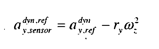
- the inventive method is characterized in that first the vehicle longitudinal speed V x is determined. Thereafter, the calculation of the dynamic driving contribution to the reference longitudinal acceleration takes place a x . ref dyn and for reference lateral acceleration a y . ref dyn from the vehicle longitudinal speed V x and the yaw rate ⁇ z . These values are used to determine the driving dynamic contribution to the reference acceleration a ⁇ . sensor dyn . ref at the position of the acceleration sensor to be compensated by transformation of the vehicle dynamic reference acceleration calculated for the vehicle center of gravity a x . ref dyn a y . ref dyn . where ⁇ describes the orientation of the sensor in the plane.
- the method according to the invention is based on the situational statistical evaluation of different sensor signals. If the inertia sensor to be compensated is mounted in the vehicle plane in any direction ⁇ , a reference value is calculated from the yaw rate ⁇ z , the steering wheel angle ⁇ and the wheel speeds V 1 , V 2 , V 3 , V 4 .
- the direction ⁇ is the angle between the vehicle longitudinal axis and the measuring direction of the acceleration sensor.
- An important basic variable for the further reference calculations is the vehicle longitudinal speed in the center of gravity, which can be calculated from the wheel speeds, the steering wheel angle ⁇ , the brake light signal BLS, and the direction of travel:
- V x V x V 1 V 2 V 3 V 4 ⁇ BLS direction of travel
- r x and r y are the longitudinal or lateral distance of the sensor position from the center of gravity of the vehicle. In this case, amounts were neglected, in which the derivation of the rotation rates, as well as the roll rate and pitch rate occur.
- a ⁇ . sensor dyn . ref a x . sensor dyn . ref ⁇ cos ⁇ ⁇ + a y . sensor dyn . ref ⁇ sin ⁇ ⁇
- the basic principle of the method according to the invention is that the earth is round on average and thus the component g II will be removed in the long run while driving.
- situation recognizers are used which detect highly dynamic driving situations and journeys on steep inclines or bank gradients as well as vehicle stoppages and exclude these for the averaging process.
- the vehicle longitudinal speed V x is calculated according to the method of the invention from the wheel speeds V 1 , V 2 , V 3 and V 4 , the steering wheel angle ⁇ , the brake light signal and the direction of travel. It is further preferred that the magnitude and the sign of the speed be determined by the wheel speed to be determined for the determination of the wheel speed is reproduced. Accordingly, the method according to the invention is based on a situational statistical evaluation of different signals.
- the offset drift of the sensor is determined as an average value, with an averaging constant of several hours is selected, since at this time scale the measured gravitational acceleration averages to zero in the situation-dependent calculation of the offset drift.
- situation recognizers are used that recognize highly dynamic driving situations and driving on steep inclines or inclines, so that these exceptional driving situations are excluded from the averaging process.
- stoppages must be excluded from the averaging process.
- the input for the method is provided by preferably five input signals.
- the input signals result from the brake light signal 1, the wheel speeds 2, the steering wheel angle 3, the yaw rate 4 and the acceleration 5. From these signals, the driving dynamic contribution to the reference longitudinal acceleration 6 and the reference lateral acceleration 7 in the vehicle's center of gravity is calculated.
- These reference accelerations 6, 7 calculated for the vehicle center of gravity are set by transformation 8 to the position of the sensor. These determined from the transformation 8 for the position of the sensor Reference accelerations form a basis for the situation-dependent averaging process 9.
- a reference speed 10 is also determined from the input signals listed above, which serves as a direct basis for the situation-dependent averaging process 9 and the reference calculations 6, 7.
- the measured values resulting from the input signals 1 to 5 are also detected and analyzed by the situation recognizer 11, the evaluation of which is incorporated both in the calculation of the reference accelerations 6, 7 and in the situation-dependent averaging process 9. From this situation-dependent averaging process 9 then results in the offset-compensated value 12 for the acceleration sensor.
- the present invention makes it possible to determine the long-term contribution to the offset of acceleration sensors which are mounted in any direction and arbitrary position in the plane of a motor vehicle. It is precisely these long-term drifts, which are very difficult to model and therefore could not be sufficiently matched by characteristics.
Abstract
Description
Die Erfindung betrifft ein Verfahren zur Bestimmung von Langzeit-Offset-Drifts von Beschleunigungssensoren in einem Kraftfahrzeug.The invention relates to a method for determining long-term offset drifts of acceleration sensors in a motor vehicle.
Derartige Verfahren zur Bestimmung von Langzeit-Offset-Drifts von Beschleunigungssensoren sind beispielsweise aus der
Typische Offset-Drifts solcher Trägheitssensoren (Inertialsensoren) können in zwei, auf unterschiedlichen Zeitskalen agierende Beiträge unterteilt werden. Drifts, welche durch Temperaturänderungen des Sensors bzw. seiner Umgebung hervorgerufen werden, erstrecken sich über einige Minuten bis wenige Stunden. Zusätzlich kommen langfristige Drifts des Sensor-Offsets hinzu, welche im Wesentlichen auf Alterungsprozesse zurückgeführt werden können und sich über Zeiträume von mehreren Tagen über Wochen bis hin zu Monaten bemerkbar machen.Typical offset drifts of such inertial sensors (inertial sensors) can be divided into two contributions acting on different timescales. Drifts, which are caused by temperature changes of the sensor or its environment, extend over several minutes to a few hours. In addition, long-term drifts of the sensor offset are added, which can be attributed mainly to aging processes and make themselves felt over periods of several days over weeks to months.
In bisherigen Erfindungen fokussiert man in der Regel auf den temperaturabhängigen Anteil des Offsets und versucht, diesen durch eine Kennlinie als Funktion der Temperatur zu ermitteln. Dazu ist aus der
Aus dem Stand der Technik sind auch hardwaretechnische Ansätze bekannt, bei denen der Offset der Ausgangsspannung durch Vergleich mit einer variablen Vergleichsspannung ermittelt wird. Dazu ist aus der
Nachteilig an den bisherigen Lösungen ist, dass weder die Temperaturabhängigkeit noch die Spannungsänderungen ideale Variablen darstellen, die einen Offset-Drift eines Beschleunigungssensors exakt bestimmen, da diese Variablen keine Größe darstellen, die in unmittelbaren Zusammenhang mit einem Offset-Drift stehen.A disadvantage of the previous solutions is that neither the temperature dependence nor the voltage changes represent ideal variables that accurately determine an offset drift of an acceleration sensor, since these variables do not represent a quantity that is directly related to an offset drift.
Hiervon ausgehend liegt der vorliegenden Erfindung die Aufgabe zugrunde, ein Verfahren zur Bestimmung von Offset-Drifts von Beschleunigungssensoren zu schaffen, das eine exakte Ermittlung und Kompensation des Langzeit-Offset-Drifts ermöglicht.Proceeding from this, the present invention has the object to provide a method for determining offset drifts of acceleration sensors, which allows an exact determination and compensation of the long-term offset drift.
Diese Aufgabe wird durch ein Verfahren mit den Merkmalen des Patentanspruchs 1 gelöst. Vorteilhafte Aus- und Weiterbildung, welche einzeln oder in Kombination miteinander eingesetzt werden können, sind der Gegenstand der abhängigen Ansprüche.This object is achieved by a method having the features of
Das erfindungsgemäße Verfahren zeichnet sich dadurch aus, dass zunächst die Fahrzeuglängsgeschwindigkeit Vx ermittelt wird. Danach erfolgt die Berechnung des fahrdynamischen Beitrags zur Referenzlängsbeschleunigung ![]()
![]()
![]()
![]()
![]()
![]()
![]()
![]()
![]()
![]()
![]()
![]()
![]()
![]()
Dem erfindungsgemäßen Verfahren liegt die situationsbedingte statistische Auswertung von verschiedenen Sensorsignalen zugrunde. Ist der zu kompensierende Trägheitssensor in der Fahrzeugebene in beliebiger Richtung θ angebracht, wird ein Referenzwert aus der Gierrate ωz , dem Lenkradwinkel δ und den Radgeschwindigkeiten V1, V2, V3, V4 berechnet. Hierbei ist die Richtung θ der Winkel zwischen der Fahrzeuglängsachse und der Messrichtung des Beschleunigungssensors. Eine wichtige Grundgröße für die weiteren Referenzberechnungen ist die Fahrzeuglängsgeschwindigkeit im Schwerpunkt, welche aus den Radgeschwindigkeiten, dem Lenkradwinkel δ, dem Bremslichtsignal BLS, und der Fahrtrichtung berechnet werden kann: ![]()
![]()
Falls die Raddrehzahlen nicht nur den Betrag sondern auch das Vorzeichen der Geschwindigkeit angeben, ist die Zusatzinformation der aktuellen Fahrtrichtung nicht mehr nötig. Es ergibt sich in einfachster Näherung für den fahrdynamischen Beitrag zur Referenzlängsbeschleunigung im Fahrzeugschwerpunkt: 
- wobei lR der Abstand vom Fahrzeugschwerpunkt zur Hinterachse ist. Der fahrdynamische Beitrag zur Referenzquerbeschleunigung ergibt sich in einfachster Näherung im Fahrzeugschwerpunkt als:

- where l R is the distance from the vehicle center of gravity to the rear axle. The driving dynamic contribution to the reference lateral acceleration results in the simplest approximation in the vehicle's center of gravity as:
Es ist auch möglich, andere Methoden zur Referenzbildung zu benutzen. Es sollte jedoch darauf geachtet werden, dass diese so einfach wie möglich sind und die eingehenden Größen keine systematischen Fehler aufweisen, die zu einer Verfälschung der nachfolgenden Mittelwertmethode führen könnten.It is also possible to use other methods of reference formation. However, care should be taken to ensure that they are as simple as possible and that the incoming quantities are free from systematic errors that could lead to a falsification of the subsequent mean method.
Um einen fahrdynamischen Referenzwert für den sich in der Ebene befindenden, zu kompensierenden Beschleunigungssensor zu erhalten, sind zwei Transformationen notwendig. Zuerst muss die im Fahrzeugschwerpunkt berechnete fahrdynamische Referenzbeschleunigung ![]()
![]()
![]()
![]()
Dabei sind rx und ry der longitudinale, bzw. laterale Abstand der Sensorposition vom Fahrzeugschwerpunkt. Dabei wurden Beträge vernachlässigt, in denen die Ableitung der Drehraten, sowie der Rollrate und Nickrate vorkommen. Um noch auf die Messrichtung θ des Sensors zu projizieren, kann folgende Relation benutzt werden 
Der Messwert, der von dem zu überwachenden Sensor wiedergegeben wird, ergibt sich aus nachfolgender Gleichung ![]()
![]()
Dabei ist ![]()
![]()
![]()
![]()
Grundlegendes Prinzip des erfindungsgemäßen Verfahrens ist, dass die Erde im Mittel rund ist und sich somit die Komponente gII langfristig beim Fahren herausmitteln wird. Diese Methode gibt die Zeitskala für den Mittlungsprozess vor. Man kann nicht für mehrere Tage ständig bergauf fahren, ohne auch mal abwärts fahren zu müssen. Somit ist eine Mittelungskonstante von mehreren Stunden sinnvoll. Demgemäß ergibt sich der langfristige Beitrag zum Sensor-Offset gemäß nachfolgender Formel ![]()
wobei der Mittelungsprozess durch die Linie angedeutet ist und ausgenutzt wurde, dass ![]()
![]()
wherein the averaging process is indicated by the line and has been exploited ![]()
Um diesen Mittelungsprozess sauber ausführen zu können, werden Situationserkenner verwendet, welche hochdynamische Fahrsituationen und Fahrten bei steilen Steigungen bzw. Querneigungen sowie Fahrzeugstillstände erkennen und diese für den Mittelungsprozess ausschließen.In order to be able to carry out this averaging process in a clean manner, situation recognizers are used which detect highly dynamic driving situations and journeys on steep inclines or bank gradients as well as vehicle stoppages and exclude these for the averaging process.
Vorzugsweise wird die Fahrzeuglängsgeschwindigkeit Vx nach dem erfindungsgemäßen Verfahren aus den Radgeschwindigkeiten V1, V2, V3 und V4, dem Lenkradwinkel δ, dem Bremslichtsignal und der Fahrtrichtung berechnet. Es ist ferner bevorzugt, dass durch die für die Bestimmung der Radgeschwindigkeit zu ermittelnde Raddrehzahl der Betrag und das Vorzeichen der Geschwindigkeit wiedergegeben wird. Demgemäß liegt dem erfindungsgemäßen Verfahren eine situationsbedingte statistische Auswertung von verschiedenen Signalen zugrunde.Preferably, the vehicle longitudinal speed V x is calculated according to the method of the invention from the wheel speeds V 1 , V 2 , V 3 and V 4 , the steering wheel angle δ, the brake light signal and the direction of travel. It is further preferred that the magnitude and the sign of the speed be determined by the wheel speed to be determined for the determination of the wheel speed is reproduced. Accordingly, the method according to the invention is based on a situational statistical evaluation of different signals.
Ferner ist es von Vorteil, wenn der Offset-Drift des Sensors als Mittelwert bestimmt wird, wobei eine Mittelungskonstante von mehreren Stunden gewählt wird, da sich bei dieser Zeitskala die gemessene Erdbeschleunigung bei der situationsbedingten Berechnung des Offset-Drifts zu Null mittelt.Further, it is advantageous if the offset drift of the sensor is determined as an average value, with an averaging constant of several hours is selected, since at this time scale the measured gravitational acceleration averages to zero in the situation-dependent calculation of the offset drift.
Ferner ist es von Vorteil, wenn Situationserkenner verwendet werden, die hochdynamische Fahrsituationen und Fahrten bei steilen Steigungen bzw. Querneigungen erkennen, so dass diese außergewöhnlichen Fahrsituationen vom Mittelungsprozess ausgeschlossen werden. Außerdem müssen Stillstände vom Mittelungsprozess ausgenommen werden.Furthermore, it is advantageous if situation recognizers are used that recognize highly dynamic driving situations and driving on steep inclines or inclines, so that these exceptional driving situations are excluded from the averaging process. In addition, stoppages must be excluded from the averaging process.
Weitere Vorteile und Ausführungen der Erfindung werden nachfolgend anhand eines Ausführungsbeispiels sowie anhand der Zeichnung erläutert.Further advantages and embodiments of the invention will be explained below with reference to an embodiment and with reference to the drawing.
Dabei zeigt schematisch:
- Fig. 1 ein Blockschaltbild des erfindungsgemäßen Verfahrens.
- Fig. 1 is a block diagram of the method according to the invention.
Fig.1 zeigt in einer schematischen Darstellung ein Blockschaltbild des erfindungsgemäßen Verfahrens. Der Input für das Verfahren wird durch vorzugsweise fünf Eingangssignale bereitgestellt. Die Eingangssignale ergeben sich aus dem Bremslichtsignal 1, den Radgeschwindigkeiten 2, dem Lenkradwinkel 3, der Gierrate 4 und der Beschleunigung 5. Aus diesen Signalen wird der fahrdynamische Beitrag zur Referenzlängsbeschleunigung 6 bzw. zur Referenzquerbeschleunigung 7 im Fahrzeugschwerpunkt berechnet. Diese für den Fahrzeugschwerpunkt berechneten Referenzbeschleunigungen 6, 7 werden durch Transformation 8 an die Position des Sensors gesetzt. Diese aus der Transformation 8 für die Position des Sensors ermittelten Referenzbeschleunigungen bilden eine Grundlage für den situationsabhängigen Mittelungsprozess 9.1 shows a schematic representation of a block diagram of the method according to the invention. The input for the method is provided by preferably five input signals. The input signals result from the
Aus den oben aufgeführten Eingangssignalen wird des Weiteren auch eine Referenzgeschwindigkeit 10 ermittelt, die als unmittelbare Grundlage für den situationsabhängigen Mittelungsprozess 9 sowie den Referenzberechnungen 6,7 dient.Furthermore, a
Die sich aus den Eingangssignalen 1 bis 5 ergebenden Messwerte werden zudem auch vom Situationserkenner 11 erfasst und analysiert, dessen Auswertung sowohl in die Berechnung der Referenzbeschleunigungen 6, 7 als auch in den situationsabhängigen Mittelungsprozess 9 einfließen. Aus diesem situationsabhängigen Mittelungsprozess 9 ergibt sich dann der Offset-kompensierte Wert 12 für den Beschleunigungssensor.The measured values resulting from the input signals 1 to 5 are also detected and analyzed by the
Die vorliegende Erfindung erlaubt es, den langfristigen Beitrag zum Offset von Beschleunigungssensoren, welche in beliebiger Richtung und beliebiger Position in der Ebene eines Kraftfahrzeugs angebracht sind, zu bestimmen. Es sind genau diese langfristigen Drifts, die sehr schlecht zu modellieren sind und daher bisher nur unzureichend durch Kennlinien abgeglichen werden konnten.The present invention makes it possible to determine the long-term contribution to the offset of acceleration sensors which are mounted in any direction and arbitrary position in the plane of a motor vehicle. It is precisely these long-term drifts, which are very difficult to model and therefore could not be sufficiently matched by characteristics.
Claims (10)
- Method for determining long-term offset drifts of acceleration sensors in a motor vehicle, with the method including the steps:- determining the longitudinal vehicle speed Vx in the centre of gravity of the vehicle;- calculating the share of the driving dynamics in the longitudinal reference acceleration

 - calculating the share of the driving dynamics in the reference acceleration in the plane by means of transformation of the driving dynamics in the reference accelerations

 - determining the long-term offset drift of the sensor from the measured values of the sensor and the proportion of the measured value in the driving dynamics by means of a situation-dependent averaging process.
 - Method according to claim 1, characterised in that the longitudinal vehicle speed Vx is calculated from the wheel speeds V1, V2. V3 and V4, the steering wheel angle δ, the stop light signal and the direction of travel.
- Method according to claim 2, characterised in that the absolute value and sign of the speed is reproduced by means of the rotational wheel speed to be ascertained for the wheel speed determination.
- Method according to one of the preceding claims, characterised in that a situation-dependent statistical evaluation of different sensor signals is implemented.
- Method according to one of the preceding claims, characterised in that the offset drift of the sensor is determined as an average value.
- Method according to claim 5, characterised in that an averaging time constant of several hours is selected.
- Method according to one of the preceding claims, characterised in that in the case of the situation-dependent averaging process the measured acceleration due to gravity is on average zero when calculating the offset drift.
- Method according to one of the preceding claims, characterised in that a situation identifier is used.
- Method according to claim 8, characterised in that the situation identifier determines highly dynamic driving situations and journeys in the case of steep gradients and/or transverse inclinations as well as standstills.
- Method according to claim 9, characterised in that highly dynamic driving situations and journeys in the case of steep gradients and/or transverse inclinations as well as standstills are excluded from the averaging process.
Applications Claiming Priority (2)
| Application Number | Priority Date | Filing Date | Title |
|---|---|---|---|
| DE102005054208A DE102005054208B3 (en) | 2005-11-14 | 2005-11-14 | Method for determining long-term offset drifts of acceleration sensors in motor vehicles |
| PCT/EP2006/066171 WO2007065740A1 (en) | 2005-11-14 | 2006-09-08 | Method for the determination of long-term offset drifts of acceleration sensors in motor vehicles |
Publications (2)
| Publication Number | Publication Date |
|---|---|
| EP1949112A1 EP1949112A1 (en) | 2008-07-30 |
| EP1949112B1 true EP1949112B1 (en) | 2009-12-09 |
Family
ID=37416193
Family Applications (1)
| Application Number | Title | Priority Date | Filing Date |
|---|---|---|---|
| EP06793355A Active EP1949112B1 (en) | 2005-11-14 | 2006-09-08 | Method for the determination of long-term offset drifts of acceleration sensors in motor vehicles |
Country Status (7)
| Country | Link |
|---|---|
| US (1) | US8489355B2 (en) |
| EP (1) | EP1949112B1 (en) |
| JP (1) | JP4976410B2 (en) |
| KR (1) | KR101358166B1 (en) |
| CN (1) | CN101322034B (en) |
| DE (2) | DE102005054208B3 (en) |
| WO (1) | WO2007065740A1 (en) |
Families Citing this family (10)
| Publication number | Priority date | Publication date | Assignee | Title |
|---|---|---|---|---|
| DE102008002000B4 (en) * | 2007-11-14 | 2021-03-25 | Robert Bosch Gmbh | Sensor arrangement with an offset position and method for offset position in a sensor arrangement |
| US8165742B2 (en) | 2008-11-14 | 2012-04-24 | Robert Bosch Gmbh | System and method for compensating sensor signals |
| JP5477316B2 (en) * | 2011-03-16 | 2014-04-23 | 株式会社アドヴィックス | Vehicle sliding-down state determination device and vehicle control device including the same |
| JP5754274B2 (en) * | 2011-07-13 | 2015-07-29 | 株式会社アドヴィックス | Output correction device for acceleration sensor for vehicle |
| DE102012222893A1 (en) * | 2012-12-12 | 2014-06-12 | Robert Bosch Gmbh | Method for determining the offset value of a sensor signal |
| WO2015081546A1 (en) | 2013-12-05 | 2015-06-11 | 华为终端有限公司 | Method and apparatus for determining acceleration of vehicle |
| DE102014207628A1 (en) | 2014-04-23 | 2015-10-29 | Continental Teves Ag & Co. Ohg | Method for determining an offset of an inertial sensor |
| DE102017223001A1 (en) * | 2017-12-18 | 2019-06-19 | Robert Bosch Gmbh | Method and device for operating an inertial sensor unit for a vehicle |
| JP2020179808A (en) * | 2019-04-26 | 2020-11-05 | トヨタ自動車株式会社 | Vehicle control apparatus |
| CN114894471B (en) * | 2022-05-09 | 2023-08-18 | 重庆大学 | Method and system for estimating dynamic transmission error of gear pair |
Family Cites Families (18)
| Publication number | Priority date | Publication date | Assignee | Title |
|---|---|---|---|---|
| DE3212611A1 (en) * | 1982-04-05 | 1983-10-06 | Bosch Gmbh Robert | METHOD FOR TEMPERATURE COMPENSATION OF A SENSOR SIGNAL |
| DE3334603A1 (en) * | 1983-09-24 | 1985-04-04 | Robert Bosch Gmbh, 7000 Stuttgart | Amplifier arrangement for an acceleration pick-up |
| JPH0740039B2 (en) | 1988-12-19 | 1995-05-01 | 日産自動車株式会社 | Vehicle acceleration detection value correction device |
| JP2878498B2 (en) * | 1991-09-13 | 1999-04-05 | 株式会社日立製作所 | Angular acceleration detector |
| DE4228893B4 (en) * | 1992-08-29 | 2004-04-08 | Robert Bosch Gmbh | System for influencing the driving dynamics of a motor vehicle |
| US6023664A (en) | 1996-10-16 | 2000-02-08 | Automotive Systems Laboratory, Inc. | Vehicle crash sensing system |
| JPH11190742A (en) | 1997-12-26 | 1999-07-13 | Nisshinbo Ind Inc | Method for detecting shift of front-back g sensor |
| US6532419B1 (en) * | 1998-09-23 | 2003-03-11 | Magellan Dis, Inc. | Calibration of multi-axis accelerometer in vehicle navigation system |
| JP2000283994A (en) | 1999-03-30 | 2000-10-13 | Aisin Seiki Co Ltd | Lateral acceleration correcting unit for vehicle, and skid angle arithmetic unit provided with same |
| KR100369130B1 (en) * | 1999-12-24 | 2003-01-24 | 현대자동차주식회사 | Sensor error minimum method of accident data recorder for vehicle |
| JP2002213944A (en) * | 2001-01-18 | 2002-07-31 | Niles Parts Co Ltd | Instrument for measuring rotational angle |
| JP4076740B2 (en) * | 2001-06-22 | 2008-04-16 | 住友ゴム工業株式会社 | Road surface gradient determination apparatus and method, and gradient determination program |
| US6675074B2 (en) * | 2001-08-21 | 2004-01-06 | Robert Bosch Gmbh | Method and system for vehicle trajectory estimation |
| DE10154341A1 (en) * | 2001-11-06 | 2003-05-15 | Volkswagen Ag | Method and device for determining a geometric inclination of a motor vehicle |
| JP2003307524A (en) * | 2002-04-15 | 2003-10-31 | Pioneer Electronic Corp | Acceleration data correction device, its correction method, its correction program, recording medium for recording its correction program and navigation device |
| JP4258430B2 (en) * | 2003-06-27 | 2009-04-30 | 日本ビクター株式会社 | Current sensor |
| CN100422009C (en) | 2003-12-12 | 2008-10-01 | 西门子公司 | Method and arrangement for monitoring a measuring device located in a wheeled vehicle |
| DE102005003292A1 (en) | 2004-04-15 | 2005-11-03 | Continental Teves Ag & Co. Ohg | Long-term offset adjustment of a sensor |
-
2005
- 2005-11-14 DE DE102005054208A patent/DE102005054208B3/en not_active Expired - Fee Related
-
2006
- 2006-09-08 JP JP2008540540A patent/JP4976410B2/en active Active
- 2006-09-08 EP EP06793355A patent/EP1949112B1/en active Active
- 2006-09-08 DE DE502006005623T patent/DE502006005623D1/en active Active
- 2006-09-08 KR KR1020087014430A patent/KR101358166B1/en active IP Right Grant
- 2006-09-08 CN CN2006800423688A patent/CN101322034B/en active Active
- 2006-09-08 WO PCT/EP2006/066171 patent/WO2007065740A1/en active Application Filing
- 2006-09-08 US US12/093,539 patent/US8489355B2/en active Active
Also Published As
| Publication number | Publication date |
|---|---|
| JP4976410B2 (en) | 2012-07-18 |
| DE502006005623D1 (en) | 2010-01-21 |
| WO2007065740A1 (en) | 2007-06-14 |
| CN101322034A (en) | 2008-12-10 |
| KR101358166B1 (en) | 2014-02-07 |
| CN101322034B (en) | 2010-12-22 |
| EP1949112A1 (en) | 2008-07-30 |
| US8489355B2 (en) | 2013-07-16 |
| US20090037129A1 (en) | 2009-02-05 |
| KR20080074982A (en) | 2008-08-13 |
| DE102005054208B3 (en) | 2007-06-14 |
| JP2009516183A (en) | 2009-04-16 |
Similar Documents
| Publication | Publication Date | Title |
|---|---|---|
| EP1949112B1 (en) | Method for the determination of long-term offset drifts of acceleration sensors in motor vehicles | |
| EP0751888B1 (en) | Circuit for processing signals from a yaw-rate sensor | |
| EP1989086B1 (en) | Method and device for determining the roll angle of a motorcycle | |
| DE102011055339B4 (en) | METHOD FOR DETERMINING A TOOTHPIECE FOR A STEERING DEVICE AND STEERING DEVICE | |
| DE102008019270B4 (en) | Road surface friction coefficient estimation device | |
| DE4223385C2 (en) | Method for recognizing the reversing of a motor vehicle | |
| DE10306829B4 (en) | Determine vehicle speeds using linear parameters and gain varying planning theories | |
| DE102015000998B4 (en) | Detecting a loose wheel | |
| DE102006018978A1 (en) | Motor vehicle roll angle determining method, involves determining yaw rate or correlated size, and vehicle speed, and determining roll angle of motor vehicle using yaw rate or correlated size and specific vehicle roll spring rigidity | |
| DE102009022592B4 (en) | Method for determining the road coefficient of friction during the operation of a motor vehicle | |
| DE102005060219A1 (en) | Estimating method for rating a friction coefficient between a road and a motor vehicle's tires uses the friction coefficient to enlarge a Kalman filter by the friction coefficient | |
| DE102007002791A1 (en) | Method and device for determining the speed of a vehicle | |
| EP1738182B1 (en) | Long-duration offset compensation of a sensor | |
| DE10360728A1 (en) | Method and device for determining a vehicle condition | |
| EP1743819B1 (en) | Method and device to calculate the yaw and roll rates in a vehicle | |
| DE102007052751A1 (en) | Tire's longitudinal rigidity determining method for vehicle control system e.g. electronic stability program system, involves calculating wheel-actual slip from wheel and balancing speeds, and calculating rigidity from slip | |
| DE102014114751A1 (en) | Method for operating a motor vehicle | |
| DE102019211934B4 (en) | Method for determining a train speed of a train with at least one car | |
| DE102017007122A1 (en) | Method for detecting the direction of travel of a vehicle | |
| DE102007061811A1 (en) | Method and device for detecting the direction of travel of a vehicle | |
| DE102018125892A1 (en) | Method for checking the plausibility of a lateral acceleration of a two-lane motor vehicle that is not bound to a track | |
| DE102018209038A1 (en) | METHOD AND CONTROL DEVICE FOR AUTOMATED LEARNING OF A STEERING WHEEL ANGLE SET IN THE OPERATION OF A VEHICLE | |
| DE102010062549B4 (en) | Method for determining the mass of a motor vehicle | |
| DE10325548B4 (en) | Apparatus and method for measuring movement quantities of a motor vehicle | |
| DE102019117981A1 (en) | Method and device for determining the coefficient of friction for a vehicle |
Legal Events
| Date | Code | Title | Description |
|---|---|---|---|
| PUAI | Public reference made under article 153(3) epc to a published international application that has entered the european phase |
Free format text: ORIGINAL CODE: 0009012 |
|
| 17P | Request for examination filed |
Effective date: 20080513 |
|
| AK | Designated contracting states |
Kind code of ref document: A1 Designated state(s): DE FR GB |
|
| 17Q | First examination report despatched |
Effective date: 20080912 |
|
| RBV | Designated contracting states (corrected) |
Designated state(s): DE FR GB |
|
| GRAP | Despatch of communication of intention to grant a patent |
Free format text: ORIGINAL CODE: EPIDOSNIGR1 |
|
| GRAS | Grant fee paid |
Free format text: ORIGINAL CODE: EPIDOSNIGR3 |
|
| GRAA | (expected) grant |
Free format text: ORIGINAL CODE: 0009210 |
|
| AK | Designated contracting states |
Kind code of ref document: B1 Designated state(s): DE FR GB |
|
| REG | Reference to a national code |
Ref country code: GB Ref legal event code: FG4D Free format text: NOT ENGLISH |
|
| REF | Corresponds to: |
Ref document number: 502006005623 Country of ref document: DE Date of ref document: 20100121 Kind code of ref document: P |
|
| PLBE | No opposition filed within time limit |
Free format text: ORIGINAL CODE: 0009261 |
|
| STAA | Information on the status of an ep patent application or granted ep patent |
Free format text: STATUS: NO OPPOSITION FILED WITHIN TIME LIMIT |
|
| 26N | No opposition filed |
Effective date: 20100910 |
|
| PGFP | Annual fee paid to national office [announced via postgrant information from national office to epo] |
Ref country code: GB Payment date: 20120920 Year of fee payment: 7 |
|
| GBPC | Gb: european patent ceased through non-payment of renewal fee |
Effective date: 20130908 |
|
| PG25 | Lapsed in a contracting state [announced via postgrant information from national office to epo] |
Ref country code: GB Free format text: LAPSE BECAUSE OF NON-PAYMENT OF DUE FEES Effective date: 20130908 |
|
| REG | Reference to a national code |
Ref country code: FR Ref legal event code: PLFP Year of fee payment: 11 |
|
| REG | Reference to a national code |
Ref country code: FR Ref legal event code: PLFP Year of fee payment: 12 |
|
| REG | Reference to a national code |
Ref country code: FR Ref legal event code: PLFP Year of fee payment: 13 |
|
| PGFP | Annual fee paid to national office [announced via postgrant information from national office to epo] |
Ref country code: FR Payment date: 20190926 Year of fee payment: 14 |
|
| REG | Reference to a national code |
Ref country code: DE Ref legal event code: R084 Ref document number: 502006005623 Country of ref document: DE |
|
| PG25 | Lapsed in a contracting state [announced via postgrant information from national office to epo] |
Ref country code: FR Free format text: LAPSE BECAUSE OF NON-PAYMENT OF DUE FEES Effective date: 20200930 |
|
| REG | Reference to a national code |
Ref country code: DE Ref legal event code: R081 Ref document number: 502006005623 Country of ref document: DE Owner name: CONTINENTAL AUTOMOTIVE TECHNOLOGIES GMBH, DE Free format text: FORMER OWNER: CONTINENTAL AUTOMOTIVE GMBH, 30165 HANNOVER, DE |
|
| PGFP | Annual fee paid to national office [announced via postgrant information from national office to epo] |
Ref country code: DE Payment date: 20220531 Year of fee payment: 17 |