EP1948266B1 - Clamps and methods for displacing fluid from inlet port paths of fluid containers - Google Patents
Clamps and methods for displacing fluid from inlet port paths of fluid containers Download PDFInfo
- Publication number
- EP1948266B1 EP1948266B1 EP06836871A EP06836871A EP1948266B1 EP 1948266 B1 EP1948266 B1 EP 1948266B1 EP 06836871 A EP06836871 A EP 06836871A EP 06836871 A EP06836871 A EP 06836871A EP 1948266 B1 EP1948266 B1 EP 1948266B1
- Authority
- EP
- European Patent Office
- Prior art keywords
- lock member
- jaw
- jaws
- fluid container
- fluid
- Prior art date
- Legal status (The legal status is an assumption and is not a legal conclusion. Google has not performed a legal analysis and makes no representation as to the accuracy of the status listed.)
- Active
Links
Images






Classifications
-
- A—HUMAN NECESSITIES
- A61—MEDICAL OR VETERINARY SCIENCE; HYGIENE
- A61L—METHODS OR APPARATUS FOR STERILISING MATERIALS OR OBJECTS IN GENERAL; DISINFECTION, STERILISATION OR DEODORISATION OF AIR; CHEMICAL ASPECTS OF BANDAGES, DRESSINGS, ABSORBENT PADS OR SURGICAL ARTICLES; MATERIALS FOR BANDAGES, DRESSINGS, ABSORBENT PADS OR SURGICAL ARTICLES
- A61L2/00—Disinfection or sterilisation of materials or objects, in general; Accessories therefor
- A61L2/02—Disinfection or sterilisation of materials or objects, in general; Accessories therefor using physical processes
-
- A—HUMAN NECESSITIES
- A61—MEDICAL OR VETERINARY SCIENCE; HYGIENE
- A61M—DEVICES FOR INTRODUCING MEDIA INTO, OR ONTO, THE BODY; DEVICES FOR TRANSDUCING BODY MEDIA OR FOR TAKING MEDIA FROM THE BODY; DEVICES FOR PRODUCING OR ENDING SLEEP OR STUPOR
- A61M1/00—Suction or pumping devices for medical purposes; Devices for carrying-off, for treatment of, or for carrying-over, body-liquids; Drainage systems
- A61M1/02—Blood transfusion apparatus
- A61M1/0272—Apparatus for treatment of blood or blood constituents prior to or for conservation, e.g. freezing, drying or centrifuging
- A61M1/0277—Frames constraining or supporting bags, e.g. during freezing
-
- A—HUMAN NECESSITIES
- A61—MEDICAL OR VETERINARY SCIENCE; HYGIENE
- A61M—DEVICES FOR INTRODUCING MEDIA INTO, OR ONTO, THE BODY; DEVICES FOR TRANSDUCING BODY MEDIA OR FOR TAKING MEDIA FROM THE BODY; DEVICES FOR PRODUCING OR ENDING SLEEP OR STUPOR
- A61M1/00—Suction or pumping devices for medical purposes; Devices for carrying-off, for treatment of, or for carrying-over, body-liquids; Drainage systems
- A61M1/36—Other treatment of blood in a by-pass of the natural circulatory system, e.g. temperature adaptation, irradiation ; Extra-corporeal blood circuits
- A61M1/3681—Other treatment of blood in a by-pass of the natural circulatory system, e.g. temperature adaptation, irradiation ; Extra-corporeal blood circuits by irradiation
- A61M1/3683—Other treatment of blood in a by-pass of the natural circulatory system, e.g. temperature adaptation, irradiation ; Extra-corporeal blood circuits by irradiation using photoactive agents
-
- A—HUMAN NECESSITIES
- A61—MEDICAL OR VETERINARY SCIENCE; HYGIENE
- A61L—METHODS OR APPARATUS FOR STERILISING MATERIALS OR OBJECTS IN GENERAL; DISINFECTION, STERILISATION OR DEODORISATION OF AIR; CHEMICAL ASPECTS OF BANDAGES, DRESSINGS, ABSORBENT PADS OR SURGICAL ARTICLES; MATERIALS FOR BANDAGES, DRESSINGS, ABSORBENT PADS OR SURGICAL ARTICLES
- A61L2103/00—Materials or objects being the target of disinfection or sterilisation
- A61L2103/05—Living organisms or biological materials
Definitions
- Contamination of blood and blood components with infectious microorganisms or pathogens creates a serious risk for patients who receive blood or blood components via blood transfusions.
- infectious microorganisms or pathogens include, but are not limited to, viruses, bacteria, bacteriophages, fungi, blood transmitted parasites, and protozoa.
- transfusable blood or blood components may include whole blood, packed red blood cells, white blood cells, platelets, and plasma, just to name a few.
- blood and blood components can be decontaminated using pathogen inactivating agents or photosensitizers which, when activated, inactivate pathogens within the blood or blood components without destroying the biological activity of the blood or blood components.
- Pathogen inactivation agents which may be useful for decontamination include the class of photosensitizers known in the art to be useful for inactivating microorganisms.
- U.S. Pat. No. 6,277,317 discloses a method and apparatus for inactivation of biological contaminants using photo sensitizers.
- the fluid to be decontaminated may be flowed through an entry port into a photopermeable bag or fluid container.
- photo permeable means that the material of the container is adequately transparent to photoradiation of the proper wavelength for activating the photosensitizer.
- the fluid containers may contain a number of ports which provide access to the interior of the container. Such ports are typically manufactured, at least in part, out of polymeric materials, which are usually more rigid than the main body portion of the fluid container.
- a first embodiment of a clamp 100 is shown in FIG. 1 and may comprise a lower jaw 102 and an upper jaw 104.
- the lower jaw 102 of clamp 100 may comprise a photopermeable main body portion 106 and may be coupled to the upper jaw 104.
- Lower and upper jaws 102, 104 may comprise a rigid metallic material, such as aluminum, for example, and photopermeable main body portion 106 may comprise a transparent material, such as quartz, for example.
- clamp 100 may further comprise a lock member 120 coupled to lower jaw 102.
- Lock member 120 may also comprise a rigid metallic material, such as aluminum, for example.
- the lower and upper jaws 102, 104 may be operatively associated so that they may be moved between a released position 103 (shown in FIGS. 1 & 2 ) and a clamped position 303 (shown in FIG. 3 ).
- clamp 100 further comprises lock member 120
- lock member 120 may be operatively associated with the lower and upper jaws 102, 104 and may be moved between an unlocked position 105 (shown in FIG. 1 ) and a locked position 305 (shown in FIG. 3 ).
- Lock member 120 may be operated to move at least one of the lower and upper jaws 102, 104 toward clamped position 303 (shown in FIG. 3 ) as lock member 120 is moved toward locked position 305 (shown in FIG. 3 ).
- the lower and upper jaws 102, 104 may be constructed in a number of different ways and may comprise any number of different sizes and shapes, some of which will be described herein. Additionally, lower and upper jaws 102, 104 may or may not be comprised of similar materials, having similar sizes and shapes, but are shown in FIGS. 1-3 as similar only for simplicity of illustration herein. Lower and upper jaws 102, 104 will now be described in detail, respectively.
- Lower jaw 102 may further comprise a slot 112, mounting tabs 150, 152, holes 154 & 156, 158 & 160, and a sensor 140, as shown in FIG. 1 .
- Lower jaw 102 may have a slot 112 sized for receiving a lock member 120, which will be described in more detail below.
- Lower jaw 102 may also comprise mounting tabs 150, 152 for coupling the lower jaw 102 with a work surface (not shown).
- lower jaw 102 may also comprise holes 154 & 156, 158 & 160 to allow the lower jaw 102 to be secured to a predetermined location on a work surface.
- the holes 154 & 156, 158 & 160 may be positioned within the mounting tabs 150, 152.
- Lower jaw 102 may further comprise a sensor 140, which may comprise any of a wide range of devices now known in the art or that may be developed in the future that are or will be suitable for use in this particular application. Consequently, the present invention should not be regarded as limited to any particular type of sensor 140.
- sensor 140 may comprise an electrical switch that is closed when the lower and upper jaws 102, 104 are in the clamped position 303 (shown in FIG. 3 ).
- sensor 140 may comprise any type of mechanical sensor which senses when the lower and upper jaws 102, 104 are in the clamped position 303.
- upper jaw 104 may also comprise a rigid frame 118 having an opening therein.
- the opening may be sized to receive a photopermeable main body portion 108, which will be described in more detail below.
- Frame 118 of the upper jaw 104 may comprise any suitably rigid material, such as aluminum or steel, for example.
- Frame 118 of upper jaw 104 may also have an approximately rectangular shape, as shown in FIGS. 1 & 3 , and may or may not have a size and shape approximately equal to those of lower jaw 102.
- Upper jaw 104 may also comprise an elongated end portion (also shown as 118 in FIGS. 1 & 3 ). Elongated end portion 118 may further comprise an angular portion (also shown as 118, best shown in FIG. 1 ) which may be used to couple upper jaw 104 to lower jaw 102. Upper jaw 104 may also comprise a rigid pin 126 protruding from one of the sides of frame 118, as shown in FIG. 1 . Pin 126 is positioned on upper jaw 104 for mating with lock member 120, as will be described in further detail below.
- Exemplary photopermeable materials for use as photopermeable main body portions 106, 108 may include, but are not limited to, quartz, glass, polycarbonate, polystyrene, polyvinyl chloride, polyolefin, or any other rigid transparent material.
- the photopermeable main body portions 106, 108 be comprised of a photopermeable material which is suitably transparent to ultraviolet wavelengths of light.
- the lower and upper jaws 102, 104 may optionally be constructed entirely of the photopermeable material itself.
- the photopermeable material may comprise only a smaller portion, such as a window area, of the lower and/or upper jaws 102, 104.
- the frames 116, 118 of the lower and upper jaws 102, 104 may surround or enclose only a few sides (i.e. less than all sides) of the photopermeable main body portions 106, 108.
- Lock member 120 may further comprise a slot 128 (shown in FIGS. 1 & 5 ) sized for receiving pin 126 on upper jaw 104, as will be described in more detail below.
- Slot 128 may comprise a curved or arcuate slot having a generally circular curvature, as shown in FIG. 5 .
- Lock member 120 may further comprise an opening 124 along axis 122 for coupling lock member 120 with the frame 116 of the lower jaw 102. As shown in FIG. 5 , opening 124 (along axis 122) may be off-center in relationship to slot 128.
- arcuate slot 128 may comprise a slot having a generally circular curvature having a center of curvature which is displaced from the opening 124 (i.e. axis 122).
- lower jaw 102 may remain stationary while upper jaw 104 may be drawn toward lower jaw 102 and toward clamped position 303 ( FIG. 3 ).
- upper jaw 104 may remain stationary while lower jaw 102 may be drawn toward upper jaw 104 and toward clamped position 303 ( FIG. 3 ).
- both the lower and upper jaws 102, 104 may be moveable with respect to one another and both jaws 102, 104 may be moved together toward clamped position 303 ( FIG. 3 ).
- the lower and upper jaws 102, 104 may be pivotally coupled together along axis 202 such that the photopermeable main body portions 106, 108 are aligned when the lower and upper jaws 102, 104 are in the clamped position 303 ( FIG. 3 ). Aligning the photopermeable main body portions 106, 108 allows an object clamped therebetween to be reached by some wavelengths of light from both above and below the clamp 100 via the photopermeable main body portions 106, 108. Thus, the photopermeable main body portions 106, 108 are critical for allowing at least some wavelengths of light to reach the object clamped therebetween, as will be described in more detail below.
- lock member 120 may comprise a slot 128 which engages pin 126 on the upper jaw 104, as lock member 120 is pivoted (in the direction indicated by arrow 132) from the unlocked position 105 ( FIG. 1 ) to the locked position 305 ( FIG. 3 ).
- the engagement of pin 126 within slot 128 may cause lock member 120 to draw the upper jaw 104 toward the lower jaw 102 and toward the clamped position 303 ( FIG. 3 ) as the lock member 120 is pivoted toward the locked position 305 ( FIG. 3 ) in the direction indicated by arrow 132.
- an exemplary clamp assembly 600 may comprise a fluid container 602 having fluid 640 therein, a lower jaw 102, and an upper jaw 104 (shown in FIG. 7 ).
- the lower jaw 102 may comprise a photopermeable main body portion 106 and the upper jaw 104 may be operatively associated with the lower jaw 102 so that at least one of the lower and/or upper jaw(s) 102,104 may be moved together to clamp a portion 604 of a fluid container 602 therebetween.
- inlet port path 608 may be used for adding blood and/or other fluids, such as photosensitizing agents, to fluid container 602, while outlet port paths 612, 614 may be used for removing fluids from fluid container 602.
- inlet port path 608 may be sealed off at end portion 630, such as by heat welding, for example, resulting in welded end portion 630.
- RF radio frequency
- clamp 100 may be similarly used to clamp outlet port paths 612, 614 as well as inlet port path 608.
- clamp 100 may be larger and may be positioned to clamp all of the port paths 608, 612, 614 of a fluid container 602.
- FIG. 7 illustrates the lower and upper jaws 102, 104 just before they crush and deform the clamped region 604.
- FIG. 7 does not show clamped region 604 as being deformed, but as the lower and upper jaws 102, 104 are further clamped together, the clamped region 604 would be crushed and would be deformed (not shown for simplicity of illustration).
- Clamp 800 may comprise lower and upper jaws 802, 804 having photopermeable main body portions 806, 808 sized to be received by frames 816, 818, as described above.
- FIGS. 8 & 9 have numbering corresponding to FIGS. 1-3 , previously described above.
- the lock member 820 may be mounted to the upper jaw 804 so that the lock member 820 can be moved between a locked position 905 ( FIG. 9 ) and an unlocked position 805 ( FIG. 8 ).
- Lock member 820 may be pivotally mounted to upper jaw 804 along pivot axis 822 and coupled to upper jaw 804 via any suitable means, such as by hinge pin 824.
- the slot 828 of the lock member 820 may be sized to engage a rod or pin 828 on the lower jaw 802 as the lock member 820 is moved from the unlocked position 805 ( FIG. 8 ) to the locked position 905 ( FIG. 9 ).
- Lock member 820 secures the lower and upper jaws 802, 804 together in the clamped position 903 ( FIG. 9 ).
- Lock member 820 may comprise one means for moving at least one of the lower and/or upper jaw(s) 802, 804 between a clamped position 903 and a released position 803.
- Clamp 1300 may comprise lower and upper jaws 1302, 1304 having photopermeable main body portions 1306, 1308 sized to be received by frames 1316, 1318, as describe above.
- FIGS. 13 & 14 have numbering corresponding to FIGS. 1-3 and FIGS. 8 & 9 , all previously described in detail above.
Landscapes
- Health & Medical Sciences (AREA)
- Heart & Thoracic Surgery (AREA)
- Vascular Medicine (AREA)
- Animal Behavior & Ethology (AREA)
- General Health & Medical Sciences (AREA)
- Public Health (AREA)
- Veterinary Medicine (AREA)
- Life Sciences & Earth Sciences (AREA)
- Engineering & Computer Science (AREA)
- Anesthesiology (AREA)
- Biomedical Technology (AREA)
- Hematology (AREA)
- Epidemiology (AREA)
- Cardiology (AREA)
- Apparatus Associated With Microorganisms And Enzymes (AREA)
- Apparatus For Disinfection Or Sterilisation (AREA)
- Extraction Or Liquid Replacement (AREA)
Abstract
Description
- Contamination of blood and blood components with infectious microorganisms or pathogens creates a serious risk for patients who receive blood or blood components via blood transfusions. Infectious microorganisms or pathogens, include, but are not limited to, viruses, bacteria, bacteriophages, fungi, blood transmitted parasites, and protozoa. Examples of transfusable blood or blood components may include whole blood, packed red blood cells, white blood cells, platelets, and plasma, just to name a few. To combat the contamination problem, blood and blood components can be decontaminated using pathogen inactivating agents or photosensitizers which, when activated, inactivate pathogens within the blood or blood components without destroying the biological activity of the blood or blood components.
- Pathogen inactivation agents which may be useful for decontamination include the class of photosensitizers known in the art to be useful for inactivating microorganisms.
U.S. Pat. No. 6,277,317 discloses a method and apparatus for inactivation of biological contaminants using photo sensitizers. - A "photosensitizer" may be defined as any compound which absorbs radiation of one or more denned wavelengths and subsequently transfers the absorbed energy to an energy acceptor. Such photosensitizers may be activated by the application of electromagnetic spectra (e.g. light or photoradiation) to inactivate pathogens with which they may interact. Additionally,
U.S. Pat. No. 6,258,577 discloses a method and apparatus for inactivation of biological contaminants using endogenous alloxazine or isoalloxazine photosensitizers. - Decontaminating blood or blood components may be done by mixing an effective amount of a photosensitizer with the fluid to be decontaminated and then exposing the fluid to an amount of photoradiation at an appropriate wavelength sufficient to activate the photosensitizer and allowing the activated photosensitizer to inactivate at least some of the pathogens contained within the fluid. The wavelength of light used may depend on the photosensitizing agent selected. The light source(s) may provide light in the visible range, the ultraviolet range, or a mixture of light in both the visable and ultraviolet ranges.
U.S. Pat. No. 6,843,961 discloses the reduction of contaminants in Mood and blood products using photosensitizers and peak wavelengths of light. - The fluid to be decontaminated may be flowed through an entry port into a photopermeable bag or fluid container. The term "photo permeable" means that the material of the container is adequately transparent to photoradiation of the proper wavelength for activating the photosensitizer. The fluid containers may contain a number of ports which provide access to the interior of the container. Such ports are typically manufactured, at least in part, out of polymeric materials, which are usually more rigid than the main body portion of the fluid container.
- During pathogen inactivation, a portion of the fluid to be inactivated may become trapped or remain within one or more of these ports. One problem with these ports is that they may be constructed from a different material, or of the same material having a different thickness, than the main body portion of the fluid container, resulting in varying thicknesses for photopermeability. Another problem with these ports is that they may contain a larger volume of fluid than can be inactivated by a given exposure to the photoradiation. Consequently, fluids trapped within these port paths during pathogen inactivation may still contain infectious pathogens after the inactivation process is completed. These infectious pathogens may then reenter the otherwise decontaminated fluid, recontaminating the fluid.
-
WO 03/086479 WO 98/22164 US 5965349 disclose clamp assemblies for photoinactivation. - The invention is defined in the claims.
- One embodiment of a clamp includes a first jaw and a second jaw. The first jaw comprises a photopermeable main body portion. The second jaw is operatively associated with the first jaw so that at least one of the first and second jaws can be moved between clamped position and a released position. The clamp is sized to receive an inlet port path of a fluid container. The claim displaces fluid in the fluid container from a clamped region of the fluid container when the first and second jaws are in the clamped position. The photopermeable main body portion of the first jaw allows some light to reach the clamped region of the fluid container.
- Also disclosed is a method which includes: positioning an inlet port path of a fluid container containing a fluid adjacent to a photopermeable main body portion of a displacement device; using the displacement device to apply a clamping force to a inlet port path of the fluid container to displace some quantity of fluid from the inlet port path of the fluid container; and illuminating at least the inlet port path of the fluid container with light, the light passing through photopermeable main body portion of the displacement device.
- Illustrative and presently preferred embodiments of the invention are illustrated in the drawings, in which:
-
FIG. 1 is a perspective view of a first embodiment of a clamp having lower and upper jaws in the released position; -
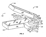
FIG. 2 is a perspective view of the clamp ofFIG. 1 having lower and upper jaws in the released position; -
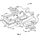
FIG. 3 is a perspective view of the clamp ofFIG. 1 having lower and upper jaws in the clamped position; -
FIG. 4 is a cross-sectional view in elevation taken along the lines 4-4 ofFIG. 3 ; -
FIG. 5 is a side view in elevation of a first embodiment of a lock member; -
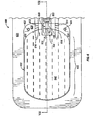
FIG. 6 is a plan view of a portion of a clamp positioned to clamp a portion of a fluid container; -
FIG. 7 is a cross-sectional view in elevation taken along the lines 7-7 ofFIG. 6 ; -
FIG. 8 is a perspective view of a second embodiment of a clamp having lower and upper jaws in the released position; -
FIG. 9 is a perspective view of the clamp ofFIG. 8 having lower and upper jaws in the clamped position; -
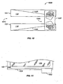
FIG. 10 is a side view in elevation of a third embodiment of a clamp; -
FIG. 11 is a plan view of a portion of the clamp ofFIG. 10 ; -
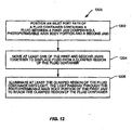
FIG. 12 is a flow chart of a method of operating a clamp to clamp a portion of a fluid container; -
FIG. 13 is a perspective view of a fourth embodiment of a clamp having lower and upper jaws in the released position; -
FIG. 14 is a side view in elevation of a second embodiment of a lock member; andFIG. 15 is a flow chart of a method of displacing fluid from a portion of a fluid container. - A first embodiment of a
clamp 100 is shown inFIG. 1 and may comprise alower jaw 102 and anupper jaw 104. Thelower jaw 102 ofclamp 100 may comprise a photopermeablemain body portion 106 and may be coupled to theupper jaw 104. Lower andupper jaws main body portion 106 may comprise a transparent material, such as quartz, for example. Additionally,clamp 100 may further comprise alock member 120 coupled tolower jaw 102.Lock member 120 may also comprise a rigid metallic material, such as aluminum, for example. - In exemplary operation, the lower and
upper jaws FIGS. 1 &2 ) and a clamped position 303 (shown inFIG. 3 ). Ifclamp 100 further compriseslock member 120,lock member 120 may be operatively associated with the lower andupper jaws FIG. 1 ) and a locked position 305 (shown inFIG. 3 ).Lock member 120 may be operated to move at least one of the lower andupper jaws FIG. 3 ) aslock member 120 is moved toward locked position 305 (shown inFIG. 3 ). - One exemplary use for
clamp 100 is shown inFIGS. 6 &7 . Lower and/or upper jaw(s) 102, 104 ofclamp 100 may be operated to clamp aportion 604 of afluid container 602 therebetween.Clamp 100 may be used to clamp portions of fluid containers, such as polymeric bags and other similar containers, such as those used for storing blood and blood components, for example.Clamp 100 may be operated to displacefluid 640 from aclamped region 604 of thefluid container 602, when at least one of the lower andupper jaws FIG. 3 ). In another embodiment,clamp 100 may be operated to preventfluid 640 from entering a clamped region (such as clamped region 604). - In one exemplary use,
clamp 100 may provide several important advantages for inactivating pathogens within a clampedportion 604 of afluid container 602, the clampedportion 604 being aport path 608 offluid container 602. Specifically,clamp 100 may displace some amount offluid 640 fromclamped region 604 and create a minimized fluid depth 642 (best shown inFIG. 7 ) within theclamped region 604 sufficient to allow activation of photosensitizer molecules via photoradiation (i.e. inactivation of pathogens) withinclamped region 604 offluid container 602. Creating a minimizedfluid depth 642 within a clampedregion 604 flattens the clampedregion 604, leaving a thinner layer of fluid therein, so that photoradiation of the clampedregion 604 can be done with a lower energy of light, increasing energy per unit of volume. - Having generally described one embodiment of
clamp 100 and how it may be operated to clamp aportion 604 of afluid container 602, as well as some of its features and advantages, several different embodiments will now be described in detail. The structural features of different embodiments of clamps will first be described herein, followed by exemplary operation of those clamps. - The lower and
upper jaws upper jaws FIGS. 1-3 as similar only for simplicity of illustration herein. Lower andupper jaws - In one exemplary embodiment, as shown in
FIG. 1 ,lower jaw 102 may comprise arigid frame 116 having an opening therein. The opening withinframe 116 may be sized to receive a photopermeablemain body portion 106, which will be described in more detail below.Frame 116 of thelower jaw 102 may comprise any suitably rigid material, such as aluminum or steel, for example.Frame 116 oflower jaw 102 may have an approximately rectangular shape, as shown inFIG 1 , and may have an elongated end portion (also shown as 116 inFIG. 1 ), which may be used to couplelower jaw 102 toupper jaw 104, as will be described in more detail below. -
Lower jaw 102 may further comprise aslot 112, mountingtabs holes 154 & 156, 158 & 160, and asensor 140, as shown inFIG. 1 .Lower jaw 102 may have aslot 112 sized for receiving alock member 120, which will be described in more detail below.Lower jaw 102 may also comprise mountingtabs lower jaw 102 with a work surface (not shown). Additionally,lower jaw 102 may also compriseholes 154 & 156, 158 & 160 to allow thelower jaw 102 to be secured to a predetermined location on a work surface. In one exemplary embodiment, as shown inFIGS. 1-3 , theholes 154 & 156, 158 & 160 may be positioned within the mountingtabs -
Lower jaw 102 may further comprise asensor 140, which may comprise any of a wide range of devices now known in the art or that may be developed in the future that are or will be suitable for use in this particular application. Consequently, the present invention should not be regarded as limited to any particular type ofsensor 140. However, by way of example, in one embodiment,sensor 140 may comprise an electrical switch that is closed when the lower andupper jaws FIG. 3 ). In another exemplary embodiment,sensor 140 may comprise any type of mechanical sensor which senses when the lower andupper jaws position 303. - With reference now to
upper jaw 104,upper jaw 104 may also comprise arigid frame 118 having an opening therein. The opening may be sized to receive a photopermeablemain body portion 108, which will be described in more detail below.Frame 118 of theupper jaw 104 may comprise any suitably rigid material, such as aluminum or steel, for example.Frame 118 ofupper jaw 104 may also have an approximately rectangular shape, as shown inFIGS. 1 &3 , and may or may not have a size and shape approximately equal to those oflower jaw 102. -
Upper jaw 104 may also comprise an elongated end portion (also shown as 118 inFIGS. 1 &3 ).Elongated end portion 118 may further comprise an angular portion (also shown as 118, best shown inFIG. 1 ) which may be used to coupleupper jaw 104 tolower jaw 102.Upper jaw 104 may also comprise arigid pin 126 protruding from one of the sides offrame 118, as shown inFIG. 1 .Pin 126 is positioned onupper jaw 104 for mating withlock member 120, as will be described in further detail below. - Lower and
upper jaws main body portions main body portions main body portions - Exemplary photopermeable materials for use as photopermeable
main body portions main body portions - In another exemplary embodiment, only one of the lower and
upper jaws photopermeable body portion upper jaws main body portion 106 or 108). In this exemplary embodiment, if illumination is desired or necessary from only one side, then only one of the lower andupper jaws main body portion 106 and/or 108. - Depending upon the use and design of lower and
upper jaws upper jaws upper jaws frames upper jaws main body portions - With reference now to
FIG. 4 , photopermeablemain body portions frames main body portions frames jaws frames main body portions surfaces surfaces - As shown in
FIG. 4 , theframes main body portions surfaces main body portion 106 is positioned within theframe 116 of thelower jaw 102, such that theframe 116 and the photopermeablemain body portion 106 together formflush clamping surface 402, resulting in a smooth surface for clamping an object. Similarly, photopermeablemain body portion 108 is positioned within theframe 118 of theupper jaw 104, such that theframe 118 and the photopermeablemain body portion 108 together formflush clamping surface 404. - As shown in
FIG. 1 , clamp 100 may further comprise alock member 120.Lock member 120 may be mounted to the lower orupper jaws FIGS. 1 &3 , as being mounted to thelower jaw 102, for example. In the exemplary embodiment shown inFIGS. 1 &2 ,lock member 120 may be mounted tolower jaw 102 withinslot 112 within theframe 116 oflower jaw 102. - With reference now to
FIG. 5 ,lock member 120 may generally comprise an elongated arm-shapedmember 120 comprised of any suitable material, such as aluminum or steel, for example.Lock member 120 may further comprise an end portion, such ashandle 130, which may be easily grasped by a user or operator when operatinglock member 120. -
Lock member 120 may further comprise a slot 128 (shown inFIGS. 1 &5 ) sized for receivingpin 126 onupper jaw 104, as will be described in more detail below.Slot 128 may comprise a curved or arcuate slot having a generally circular curvature, as shown inFIG. 5 .Lock member 120 may further comprise anopening 124 alongaxis 122 forcoupling lock member 120 with theframe 116 of thelower jaw 102. As shown inFIG. 5 , opening 124 (along axis 122) may be off-center in relationship to slot 128. Specifically,arcuate slot 128 may comprise a slot having a generally circular curvature having a center of curvature which is displaced from the opening 124 (i.e. axis 122). - As shown in
FIGS. 1-3 , the lower andupper jaws upper jaws FIG. 3 ) and a released position 103 (shown inFIGS. 1 &2 ). The lower andupper jaws - In one exemplary embodiment, as best shown in
FIG. 2 , the lower andupper jaws frames pivot axis 202. The lower andupper jaws pivot axis 202 by apin 204 such that at least one of the jaws may be moved between a clamped position 303 (FIG. 3 ) and a released position 103 (FIG. 1 ). The pivotal coupling of lower andupper jaws pivot axis 202 withpin 204 is one means for coupling the lower andupper jaws jaws FIG. 3 ) and a released position 103 (FIGS. 1 &2 ). - In one exemplary embodiment, as shown in
FIG. 1 ,lower jaw 102 may remain stationary whileupper jaw 104 may be drawn towardlower jaw 102 and toward clamped position 303 (FIG. 3 ). Alternatively,upper jaw 104 may remain stationary whilelower jaw 102 may be drawn towardupper jaw 104 and toward clamped position 303 (FIG. 3 ). In yet another embodiment, both the lower andupper jaws jaws FIG. 3 ). - In an alternative embodiment, the lower and
upper jaws upper jaws Clamp 100 is shown inFIG. 2 withoutlock member 120 for purposes of clearly illustrating an exemplary embodiment of coupling the lower andupper jaws FIG. 2 ) may also compriselock member 120, as shown inFIG. 1 . - As shown in
FIGS. 2 &3 , the lower andupper jaws axis 202 such that the photopermeablemain body portions upper jaws FIG. 3 ). Aligning the photopermeablemain body portions clamp 100 via the photopermeablemain body portions main body portions - With reference now to
FIGS. 1 &3 ,lock member 120 may be mounted tolower jaw 102 withinslot 112 so that it may be moved in the direction indicated byarrow 132 between a locked position 305 (shown inFIG. 3 ) and an unlocked position 105 (shown inFIG. 1 ).Lock member 120 may be mounted to thelower jaw 102 such that it engages theupper jaw 104 as it is moved from theunlocked position 105 to the lockedposition 305. As shown inFIG. 1 , for example,lock member 120 may be mounted tolower jaw 102 withinslot 112 withinframe 116 oflower jaw 102.Lock member 120 is one means for moving at least one of the lower andupper jaws FIG. 3 ) and a released position 103 (FIG. 1 ). - In one exemplary embodiment,
lock member 120 may be pivotally mounted tolower jaw 102, such as alongpivot axis 122, by inserting a pin or other retaining mechanism intoopening 124. In this embodiment,lock member 120 may be mounted tolower jaw 102 for rotation aboutpivot axis 122 so that it may be pivoted between an unlocked position 105 (FIG. 1 ) and a locked position 305 (FIG. 3 ) in the direction indicated byarrow 132. - In one exemplary embodiment, as shown in
FIGS. 1 &3 ,lock member 120 may comprise aslot 128 which engagespin 126 on theupper jaw 104, aslock member 120 is pivoted (in the direction indicated by arrow 132) from the unlocked position 105 (FIG. 1 ) to the locked position 305 (FIG. 3 ). In one embodiment, the engagement ofpin 126 withinslot 128 may causelock member 120 to draw theupper jaw 104 toward thelower jaw 102 and toward the clamped position 303 (FIG. 3 ) as thelock member 120 is pivoted toward the locked position 305 (FIG. 3 ) in the direction indicated byarrow 132. - In an alternative embodiment (shown best in
FIGS. 8 & 9 ), the engagement ofpin 126 withinslot 128 may retainlock member 120 in the lockedposition 305 and may hold the lower andupper jaws FIG. 3 ). In one embodiment (shown best inFIG. 14 ), theslot 128/1428 may have acrest 1429 therein to more securely retain thelock member 120/1320 in the locked position. In another alternative embodiment (not shown),lock member 120 may be designed to open at least one, or both, of the lower andupper jaws FIG. 1 ) as thelock member 120 is pivoted toward the locked position 305 (FIG. 3 ). - As shown in
FIG. 5 , theslot 128 oflock member 120 may comprise anarcuate slot 128 curved so that the engagement of thepin 126 in thearcuate slot 128 slideably draws theupper jaw 104 closer to thelower jaw 102 as thelock member 120 pivots toward the locked position 305 (FIG. 3 ) in the direction indicated byarrow 132.Slot 128 may have a generally circular curvature having a center of curvature that is displaced from thepivot axis 122, resulting in eccentric clamping between lower andupper jaws - An exemplary use of
clamp 100 is shown inFIG. 6 , wherein anexemplary clamp assembly 600 may comprise afluid container 602 havingfluid 640 therein, alower jaw 102, and an upper jaw 104 (shown inFIG. 7 ). As shown inFIG. 6 , and described above, thelower jaw 102 may comprise a photopermeablemain body portion 106 and theupper jaw 104 may be operatively associated with thelower jaw 102 so that at least one of the lower and/or upper jaw(s) 102,104 may be moved together to clamp aportion 604 of afluid container 602 therebetween. - The positioning of the photopermeable
main body portions clamp 100 with respect to a portion of the fluid container to be clamped therebetween (such as portion 604) is important for allowing some wavelengths of light to reach the clampedportion 604 of thefluid container 602, as shown inFIG. 6 . In the embodiment shown inFIG. 6 ,fluid container 602 may be positioned on a platen orwork surface 620 and may be positioned at a predetermined location on theplaten 620 by aligningpins platen 620 withholes end portion 626 offluid container 602. In one embodiment alignment of theholes fluid container 602 withpins work surface 620 may also align a predetermined portion (such as portion(s) 604 and/or 608) of thefluid container 602 with the photopermeable main body portions 106,108 of theclamp 100. - According to the invention, the
inlet port path 608 of thefluid container 602 is clamped. It may be desirable to clamp such that theinlet port path 608 is aligned within the photopermeablemain body portions fluid container 602 onwork surface 620 may also align theinlet port path 608 of thefluid container 602 with the photopermeablemain body portions clamp 100. In one exemplary embodiment,fluid container 602 may be carefully aligned withclamp 100 to clamp only a minimal portion of thefluid container 602, such as only theinlet port path 608, to avoid over-exposing the remainder of the clampedportion 604 of thefluid container 602 to photoradiation (which may destroy biological activity of the fluid 640). - Fluid containers commonly comprise
multiple port paths fluid container 602. As shown inFIG. 6 , for example,fluid container 602 may comprise oneinlet port path 608 and twooutlet port paths port paths port paths port paths - Typically,
inlet port path 608 may be used for adding blood and/or other fluids, such as photosensitizing agents, tofluid container 602, whileoutlet port paths fluid container 602. Afterfluids 640 are added tofluid container 602,inlet port path 608 may be sealed off atend portion 630, such as by heat welding, for example, resulting in weldedend portion 630. It is known in the art to seal off the inlet ports and/or outlet ports of fluid containers during use, such as is done by using electromagnetic or radio frequency (RF) energy as disclosed inU.S. Pat. No. 5,685,875 to Hlavinka . Various sorts of electromagnetic energies may be applied to create such seals, however, the choice of materials used in the inlet ports and/oroutlet ports - The
outlet port paths fluid container 602 wishing to remove the fluid 640 from thefluid container 602. The user may remove fluid 640 by breaking off break-awayend portions frangibles outlet port paths embodiment having frangibles outlet port paths outlet port paths frangibles outlet port paths - However, in other embodiments, such as where
frangibles fluid container 602, or are flexibly crushable (i.e. deformable), it maybe desirable to clamp theoutlet port paths inlet port path 608. Thus, clamp 100 may be similarly used to clampoutlet port paths inlet port path 608. In yet another embodiment, clamp 100 may be larger and may be positioned to clamp all of theport paths fluid container 602. - With reference now to
FIGS. 6 &7 , as the lower andupper jaws region 604 will be crushed.FIG. 7 illustrates the lower andupper jaws region 604. Thus,FIG. 7 does not show clampedregion 604 as being deformed, but as the lower andupper jaws region 604 would be crushed and would be deformed (not shown for simplicity of illustration). - With continuing reference to
FIGS. 6 &7 , as the lower andupper jaws inlet port path 608 will be forced out into the unclampedregion 606 of thefluid container 602, in the direction indicated by arrows 610 (shown inFIG. 7 ). Any fluid 640 remaining within theinlet port path 608 may be minimal enough indepth 642 to be effectively photoradiated to activate photosensitizer molecules within inlet port path 608 (i.e. to inactivate pathogens within the inlet port path 608). Whenclamp 100 crushes and deformsinlet port path 608 it may also flatten theinlet port path 608, resulting in a more uniform and/or flat surface having a thinner layer offluid 640 therein for photoradiation, which may increase energy per until volume during photoradiation, increasing ability to activate photosensitizer molecules therein (i.e. increasing pathogen inactivation success). In yet another embodiment, clamp 100 may be operated to prevent fluid 640 from entering clamped region 604 (in the opposite direction of arrows 610). - The portion of
clamp 100 illustrated inFIG. 6 is shown without alock member 120, pivot axis and/or pin 202/204, or mountingtabs lock member 120, pivot axis and/or pin 202/204, and mountingtabs fluid container 602 may be pressed between two additional surfaces (not shown) during a pathogen inactivation process; however this is also not illustrated inFIG. 6 for simplicity of illustration. - In one exemplary embodiment a
method 1200 for operating a clamp is disclosed and shown inFIG. 12 . Theclamp operation 1200 begins by positioning 1202 aportion 604 of afluid container 602, having a fluid 640 therein, between alower jaw 102 comprising a photopermeablemain body portion 106 and anupper jaw 104. As described above, if photoradiation from both above and belowclamp 100 is desirable, then both the lower andupper jaws main body portions region 604 therebetween. Alternatively, if photoradiation from only one side ofclamp 100 is desired, then only one of thejaws main body portion - After positioning 1202 the
fluid container 602, at least one of the lower and/or upper jaw(s) 102, 104 are moved 1204 together to displace fluid 640 from a clampedregion 604 of thefluid container 602. The clampedregion 604 offluid container 602 comprises aninlet port path 608 and anunclamped region 606 of thefluid container 602 may comprises themain body portion 606 of thefluid container 602. In this arrangement, clamping theinlet port path 608 will squeeze some amount offluid 640 out of theinlet port path 608 and into the unclampedportion 606 of thefluid container 602, in the direction indicated by arrows 610 (shown inFIG. 7 ). - After moving the lower and
upper jaws region 604 of thefluid container 602 is illuminated 1206 with light. In one exemplary embodiment, the entirefluid container 602 may be illuminated and illumination may comprise photoradiating thefluid container 602 to activate a photosensitizing agent to inactivate pathogens. In this exemplary embodiment, the light or photoradiation may pass through the photopermeablemain body portion 108 of theupper jaw 104 to photoradiate theinlet port path 608 within the clampedregion 604 of thefluid container 602. - The specific wavelength of light used during photoradiation may depend on the specific photosensitizing agent selected, as will be known by those of ordinary skill in the art after having become familiar with the teachings herein. The light or photoradiation may be provided by a light source (not shown), which may provide light having wavelengths in the visible range, the ultraviolet range, or a mixture of light in both the visable and ultraviolet ranges. In one exemplary embodiment, ultraviolet wavelengths of light may be used, more specifically; UVB wavelengths of light may be used. In some embodiments, wavelengths of light of approximately 450 nm may be used for photoradiating platelets or plasma, for example.
- In another exemplary embodiment a
method 1500 for displacing fluid from an portion of a fluid container is disclosed and shown inFIG. 15 . Themethod 1500 of displacing fluid begins by positioning 1502 a portion of a fluid container containing a fluid adjacent to a photopermeable main body portion of a displacement device. The displacement device may generally comprise aclamp 100 or may comprise a device such as a flexible or pressure-driven device, such as air-filled bags having photopermeable main body portions therein. In one embodiment aclamp 100 may be operated according tomethod 1500 using pneumatic pressure to operate clampingjaws jaws other jaw - After positioning 1502 a portion of a fluid container, the displacement device may be used 1504 to apply a displacing force to a portion of the fluid container to displace some quantity of fluid from the portion of the fluid container. After displacing some quantity of fluid from the portion of the fluid container, the portion of the fluid container may be illuminated 1506 with light. The light passing through the photopermeable main body portion of the displacement device to illuminate 1506 at least the portion of the fluid container.
- The portion of the fluid container is an inlet port path.
- Another exemplary embodiment of a
clamp 800 is shown inFIGS. 8 & 9 .Clamp 800 may comprise lower andupper jaws main body portions frames -
FIGS. 8 & 9 have numbering corresponding toFIGS. 1-3 , previously described above. -
Lower jaw 802 may have an approximately square shape whileupper jaw 804 may have an approximately trapezoidal shape. As will be known by those of ordinary skill in the art after having become familiar with the teachings herein, any number of geometric shapes may be used to construct the lower andupper jaws FIGS. 8 & 9 , the lower andupper jaws main body portions position 903 to clamp an object or portion of an object therebetween such that the object may be photoradiated while being clamped. -
Clamp 800 may further comprise alock member 820 coupled toupper jaw 804.Lock member 820 may comprise a rigid elongated arm-shaped member having aslot 828 on one end.Lock member 820 may comprise any suitably rigid material, such as aluminum or steel, for example.Slot 828 may be cut into one end oflock member 820 such thatlock member 820 forms a hooked-portion on one end. The opposite end oflock member 820 may comprise an elongated portion which may be easily grasped and moved by a user.Clamp 800 may further comprise asensor 840, mountingtabs alignment holes 854 & 856, 858 & 860, similar to those described above with respect toFIGS. 1-3 . - In one embodiment, as shown in
FIGS. 8 & 9 , for example, lower andupper jaws FIG. 9 ) and a released position 803 (FIG. 8 ). Lower andupper jaws FIGS. 8 & 9 ) such that the lower andupper jaws FIG. 9 ) and the released position 803 (FIG. 8 ), as described above with respect toFIGS. 1-3 . - As shown in
FIGS. 8 & 9 , thelock member 820 may be mounted to theupper jaw 804 so that thelock member 820 can be moved between a locked position 905 (FIG. 9 ) and an unlocked position 805 (FIG. 8 ).Lock member 820 may be pivotally mounted toupper jaw 804 alongpivot axis 822 and coupled toupper jaw 804 via any suitable means, such as byhinge pin 824. Theslot 828 of thelock member 820 may be sized to engage a rod or pin 828 on thelower jaw 802 as thelock member 820 is moved from the unlocked position 805 (FIG. 8 ) to the locked position 905 (FIG. 9 ).Lock member 820 secures the lower andupper jaws FIG. 9 ).Lock member 820 may comprise one means for moving at least one of the lower and/or upper jaw(s) 802, 804 between a clampedposition 903 and a releasedposition 803. - Yet another embodiment is shown and described with reference to
FIGS. 13 & 14 .Clamp 1300 may comprise lower andupper jaws main body portions frames FIGS. 13 & 14 have numbering corresponding toFIGS. 1-3 andFIGS. 8 & 9 , all previously described in detail above. - As illustrated in
FIGS. 13 and 14 , aclamp 1300 may be provided with an interlock system (shown generally as 1300) to prevent thelock member 1320 from remaining in the locked position (905 shown inFIG. 9 ) unless afluid container 602 is present and properly positioned between thejaws clamp 1300. In one embodiment,interlock system 1300 may comprise a small rib or crest 1429 (best shown inFIG. 14 ) formed in theslot 1428 oflock member 1320. The rib orcrest 1429 is sized and positioned withinslot 1428 oflock member 1320 so as to engage apin 1326, provided onlower jaw 1302, whenlock member 1320 is in the locked position (905 shown inFIG. 9 ). - Interlock system (generally 1300) may also comprise a biasing device or
spring 1370 operatively associated withlock member 1320 for biasinglock member 1320 to the unlocked position 1305 (shown inFIG. 13 ). If afluid container 602 is absent or not properly positioned between thejaws clamp 1300, thespring 1370 will returnlock member 1320 to theunlocked position 1305. Accordingly,interlock system 1300 may provide a more positive indication to a user that thefluid container 602 is absent or not properly positioned between thejaws clamp 1300. - More specifically, if the
fluid container 602 is absent or not properly positioned between thejaws clamp 1300, no opposing force (or an insufficient opposing force) will be provided to thejaws clamp 1300 when thelock member 1320 is in the locked position (905 shown inFIG. 9 ). Thus, the engagement of pin 1326 (on jaw 1302) with thecrest 1429 formed in theslot 1428 in thelock member 1320 will be such that thepin 1326 will not provide sufficient opposing force on thecrest 1429 to prevent thespring 1370 from returning thelock member 1320 to theunlocked position 1305. That is, in order forlock member 1320 to be returned to theunlocked position 1305, thecrest 1429 formed inslot 1428 oflock member 1320 will exert a force onpin 1326 that will urge at least one of the jaw(s) 1302, 1304 ofclamp 1300 together. Thus, if thefluid container 602 is absent or not properly positioned between thejaws jaws spring 1370 to returnlock member 1320 to theunlocked position 1305. - However, if a
fluid container 602 is properly positioned betweenjaws clamp 1300, the compliant material of thefluid container 602 will oppose the further closing of thejaws pin 1326 from being moved to the degree necessary to clear thecrest 1429 of theslot 1428 and preventingspring 1370 from returninglock member 1320 to theunlocked position 1305. Stated another way, if thefluid container 602 is properly positioned between thejaws clamp 1300, thespring 1370 will not be able to overcome the cooperative engagement of thepin 1326 and thecrest 1429 andlock member 1320 will remain in the locked position (905 shown inFIG. 9 ). - The interlock system (generally 1300) may be provided with additional components if necessary or desired to enhance operation. For example, in one embodiment, interlock system (generally 1300) may also comprise a biasing device or
spring 1372, operatively associated with thejaws clamp 1300. Thespring 1372 may be arranged to bias thejaws clamp 1300 to theunclamped position 1303. Thus, in an operational situation wherein theinterlock system 1300 causeslock member 1320 to be returned to theunlocked position 1305, thespring 1372 will cause thejaws unclamped position 1303. - The unclamping 1303 of
jaws clamp 1300 may provide an additional indication to a user that thefluid container 602 is absent or not properly positioned betweenjaws clamp 1300. If such a biasing device orspring 1372 is provided to bias thejaws unclamped position 1303, the biasing force should not be so great as to prevent thespring 1372 from returning thelock member 1320 to theunlocked position 1305 if thefluid container 602 is absent or not properly positioned between thejaws clamp 1300, in the manner already described. - Yet another embodiment is shown and described with regard to
FIGS. 10 &11.Clamp 1000 may comprise lower andupper jaws frames main body portions Clamp 1000 may further comprise alock member 1002.Lock member 1002 may generally comprise a rigid rectangular or buckle-shaped mechanism.Lock member 1002 may comprise any suitably rigid material, such as aluminum or steel, and may even comprise a rigid photopermeable material, as described above. -
Clamp 1000 may further compriseramps ramps ramps lock member 1002, to move the lower andupper jaws position 1010. - The lower and
upper jaws FIG. 10 ). The lower andupper jaws lock member 1002.Lock member 1002 may be operated to slideably draw the lower andupper jaws lock member 1002 proceeds up theramps Lock member 1002 is shown inFIG. 10 in theunlocked position 1005 with the lower andupper jaws lock member 1002 slides up theramps upper jaws - It should be understood that various changes and modifications to the presently preferred embodiments described herein will be apparent to those of ordinary skill in the art after having become familiar with the teachings provided herein. It is foreseeable that the shape and size of the clamps and displacement devices, as well as the number of clamps and displacement devices used on one fluid container may be varied. It is also foreseeable that the clamps and displacement devices may be manufactured out of a plurality of different materials having a plurality of different thicknesses, including different photopermeable materials.
- Additionally, different applications and intended uses for the clamps and displacement devices disclosed herein are also contemplated. These examples are not meant to be limiting, but rather are exemplary of the modifications that can be made without departing from the scope of the present invention as defined in the claims.
Claims (26)
- A clamp assembly comprising:a fluid container (602) containing a fluid (640) and comprising a main body portion (606) and an inlet port path (608) for flowing fluid into the fluid container (602);a clamp (100, 800, 1300) comprising:a first jaw (102) comprising a photopermeable main body portion (106); anda second jaw (104) operatively associated with the first jaw so that at least one of the first and second jaws can be moved between a clamped position (303) and a released position (103);wherein a portion of the fluid container (602) is positioned between the first and second jaws such that at least one of the first and second jaws applies a clamping force to the portion of the fluid container to displace some fluid from the clamped region to the main body portion (606) of the fluid container, the photopermeable main body portion of the first jaw allowing some light to reach the clamped region of the fluid container;characterised in that said portion of the fluid container is an inlet port path (608) of the fluid container.
- The clamp assembly of claim 1, wherein the second jaw comprises a photopermeable main body portion (108).
- The clamp assembly of claim 2, wherein the photopermeable main body portions of the first and second jaws comprise quartz.
- The clamp assembly of claim 1, further comprising a lock member (120) mounted to the second jaw so that the lock member can be moved between a locked position (305) and an unlocked position (105), the lock member engaging the first jaw and holding the first and second jaws in the clamped position (303) when the lock member is in the locked position.
- The clamp assembly of claim 4, further comprising an interlock (1300) operatively associated with the lock member (1320), the interlock preventing the lock member from remaining in the locked position unless the fluid container is positioned between the first and second jaws.
- The clamp assembly of claim 5, wherein the interlock further comprises a spring (1370), the spring biasing the lock member toward the unlocked position when the fluid container is not positioned between the first and second jaws.
- The clamp assembly of claim 6, wherein the lock member defines a slot (1428) having a crest (1429) therein and wherein the first jaw comprises a pin (1326) sized to be received by the slot in the lock member, the slot in the lock member engaging the pin on the first jaw as the lock member is moved toward the locked position, and wherein the crest in the slot retains the lock member in the locked position when the fluid container is positioned between the first and second jaws.
- The clamp assembly of claim 1, wherein the first and second jaws are pivotally connected together along a pivot axis (202).
- The clamp assembly of claim 8, further comprising a lock member (120) mounted to the first jaw so that the lock member can be moved between a locked position and an unlocked position, the lock member engaging the second jaw as the lock member is moved from the unlocked position to the locked position, the lock member drawing the first and second jaws together toward the clamped position as the lock member is moved toward the locked position.
- The clamp assembly of claim 8, further comprising a lock member (120) mounted to the first jaw so that the lock member can be moved between a locked position and an unlocked position, the lock member engaging the second jaw as the lock member is moved from the unlocked position to the locked position, the lock member drawing the second jaw toward the first jaw as the lock member is moved toward the locked position.
- The clamp assembly of claim 10, wherein the lock member defines a slot (128) therein and wherein the second jaw comprises a pin (204) sized to be received by the slot in the lock member, the slot in the lock member engaging the pin on the second jaw as the lock member is moved toward the locked position.
- The clamp assembly of claim 8, further comprising a lock member having a slot therein, wherein the lock member is mounted for rotation about a pivot axis (126) so that the lock member can be pivoted between a locked position and an unlocked position, the slot in the lock member engaging a pin on the second jaw as the lock member is pivoted from the unlocked position to the locked position, the lock member drawing the second jaw toward the first jaw and toward the clamped position as the lock member is pivoted toward the locked position.
- The clamp assembly of claim 12, wherein the slot (128) comprises an arcuate slot curved so that the engagement of the pin in the arcuate slot draws the second jaw closer to the first jaw as the lock member pivots toward the locked position; wherein the arcuate slot has a generally circular curvature having a center of curvature that is displaced from the pivot axis.
- The clamp assembly of claim 1, wherein the first jaw comprises a frame (116), the frame sized to receive the photopermeable main body portion.
- The clamp assembly of claim 1, further comprising a sensor (140) for sensing when at least one of the first and second jaws are in the clamped position.
- The clamp assembly (100) of claim 1 wherein:the first jaw further comprises:a frame (116), the frame of the first jaw defining an opening therein; andwherein the photopermeable main body portion (106) is sized to be received by the opening defined by the frame of the first jaw;the second jaw further comprises:a frame (118), the frame of the second jaw defining an opening therein; andwherein a photopermeable main body portion (108) sized to be received by the opening defined by the frame of the second jaw;the frames (116, 118) of the first and second jaws being pivotally connected together so that at least one of the first and second jaws can be pivoted about a pivot axis between the clamped position and the released position; anda lock member (120, 1320) operatively associated with the frames of the first and second jaws so that the lock member can be moved between an unlocked position and a locked position, the lock member engaging the first jaw as the lock member is moved from the unlocked position to the locked position, the lock member drawing the first jaw toward the second jaw and toward the clamped position as the lock member is moved toward the locked position.
- The clamp assembly of claim 16, further comprising an interlock (1300) operatively associated with the lock member, the interlock allowing the lock member to remain in the locked position and retaining the first and second jaws in the clamped position when a fluid container is positioned between the first and second jaws.
- The clamp assembly of claim 16, wherein the lock member defines a slot (128) therein and wherein the first jaw comprises a pin (204) sized to be received by the slot in the lock member, the slot engaging the pin on the first jaw as the lock member is pivoted toward the locked position.
- The clamp assembly of claim 18, wherein the slot further comprises an arcuate slot curved so that the engagement of the pin in the arcuate slot draws the first jaw closer to the second jaw as the lock member pivots toward the locked position; wherein the arcuate slot has a generally circular curvature having a center of curvature that is displaced from a pivot axis.
- The clamp assembly of claim 1, further comprising:a means for moving at least one of the first and second jaws between the clamped position and the released position, wherein the means is operatively associated with at least one of the first and second jaws, the first and second jaws applying a clamping force to the clamped inlet port path (608) of the fluid container positioned between the first and second jaws when the first and second jaws are in the clamped position.
- The clamp assembly of claim 21, further comprising a lock member operatively associated with the first and second jaws so that the lock member can be moved between an unlocked position and a locked position, the lock member engaging the first jaw as the lock member is moved from the unlocked position to the locked position, the lock member drawing the first jaw toward the second jaw and toward the clamped position as the lock member is moved toward the locked position.
- A method, comprising:positioning a portion of a fluid container containing a fluid adjacent to a photopermeable main body portion of a displacement device;using the displacement device to apply a clamping force to said portion of the fluid container to displace some quantity of fluid from the portion of the fluid container; andilluminating at least the portion of the fluid container with light, the light passing through the photopermeable main body portion of the displacement device;characterised in that said portion of the fluid container is an inlet port path (608) of the fluid container.
- The method of claim 22, wherein said positioning comprises positioning said inlet port path of the fluid container between a first jaw comprising the photopermeable main body portion and a second jaw, wherein the first and second jaws form the displacement device; and
said using comprises moving at least one of the first and second jaws together to provide the clamping force to displace fluid from the clamped inlet port path of the fluid container. - The method of claim 23, wherein illuminating at least the inlet port path of the fluid container comprises illuminating with ultraviolet light.
- The method of claim 23, wherein moving at least one of the first and second jaws together further comprises moving a lock member, operatively associated with the first and second jaws, to draw the first jaw toward the second jaw.
- The method of claim 22, wherein the clamp assembly of any one of claims 1 to 21 is used and wherein using said displacement device comprises:moving at least one of said first and second jaws together to apply said clamping force to the inlet port path (608) of said fluid container to displace some fluid from the inlet port path (608) to the main body portion (606) of the fluid container.
Applications Claiming Priority (2)
| Application Number | Priority Date | Filing Date | Title |
|---|---|---|---|
| US11/268,077 US20070102858A1 (en) | 2005-11-07 | 2005-11-07 | Clamps and methods for displacing fluid from portions of fluid containers |
| PCT/US2006/042934 WO2007056126A1 (en) | 2005-11-07 | 2006-11-03 | Clamps and methods for displacing fluid from portions of fluid containers |
Publications (2)
| Publication Number | Publication Date |
|---|---|
| EP1948266A1 EP1948266A1 (en) | 2008-07-30 |
| EP1948266B1 true EP1948266B1 (en) | 2010-07-28 |
Family
ID=37716040
Family Applications (1)
| Application Number | Title | Priority Date | Filing Date |
|---|---|---|---|
| EP06836871A Active EP1948266B1 (en) | 2005-11-07 | 2006-11-03 | Clamps and methods for displacing fluid from inlet port paths of fluid containers |
Country Status (6)
| Country | Link |
|---|---|
| US (2) | US20070102858A1 (en) |
| EP (1) | EP1948266B1 (en) |
| AT (1) | ATE475440T1 (en) |
| CA (1) | CA2626677C (en) |
| DE (1) | DE602006015839D1 (en) |
| WO (1) | WO2007056126A1 (en) |
Families Citing this family (5)
| Publication number | Priority date | Publication date | Assignee | Title |
|---|---|---|---|---|
| JP5369235B2 (en) * | 2010-06-24 | 2013-12-18 | Ykk株式会社 | Piping slider |
| US8940228B2 (en) | 2012-01-11 | 2015-01-27 | Terumo Bct, Inc. | Slidable clamp for port isolation |
| KR101569379B1 (en) | 2014-03-25 | 2015-11-16 | 이형석 | Aapparatus for sensing the exhaustion of Ringer Solution |
| DE102020205036B4 (en) * | 2020-04-21 | 2022-08-11 | Fraunhofer-Gesellschaft zur Förderung der angewandten Forschung e.V. | Device and method for generating a liquid film of a liquid medium in a film bag, and arrangement for the controlled exposure of a liquid medium in a film bag to physical radiation |
| CN113996447B (en) * | 2021-09-27 | 2024-12-27 | 成都恒必康科技有限公司 | Plasma bag residual liquid recovery device and plasma bag residual liquid recovery method |
Family Cites Families (31)
| Publication number | Priority date | Publication date | Assignee | Title |
|---|---|---|---|---|
| US4469227A (en) * | 1983-08-17 | 1984-09-04 | Clifford Faust | Package for cryogenically frozen liquids |
| GB2150082A (en) * | 1983-10-31 | 1985-06-26 | Michael Alfred Fitch | Complete sailboard security device |
| US4866282A (en) * | 1986-08-26 | 1989-09-12 | Baxter International Inc. | Irradiation of blood products |
| US4952812A (en) * | 1986-08-26 | 1990-08-28 | Baxter International Inc. | Irradiation of blood products |
| US4726949A (en) * | 1986-08-26 | 1988-02-23 | Baxter Travenol Laboratories, Inc. | Irradiation of blood products |
| US4878896A (en) * | 1987-12-01 | 1989-11-07 | Pacesetter Infusion, Ltd. | Cassette optical identification apparatus for a medication infusion system |
| BE1004698A3 (en) * | 1991-03-12 | 1993-01-12 | Terumo Europ Nv | Device for the separation of fluids. |
| EP0551453B1 (en) * | 1991-05-08 | 1995-01-18 | Baxter International Inc. | Container for irradiation of blood products |
| US5618662A (en) * | 1992-03-02 | 1997-04-08 | Cerus Corporation | Intravenous administration of psoralen |
| US5345070A (en) * | 1992-09-25 | 1994-09-06 | Cobe Laboratories, Inc. | Radio frequency tubing sealer |
| JP3167477B2 (en) * | 1993-02-03 | 2001-05-21 | テルモ株式会社 | Liquid separation device |
| US5547108A (en) * | 1994-08-02 | 1996-08-20 | Pall Corporation | Expressor |
| US6158319A (en) * | 1994-12-20 | 2000-12-12 | Baxter International Inc. | System to identify the status of bags that have been subjected to viral inactivation |
| US5702357A (en) * | 1995-06-07 | 1997-12-30 | Cobe Laboratories, Inc. | Extracorporeal blood processing methods and apparatus |
| DE69731308T2 (en) * | 1996-11-22 | 2005-11-17 | Therakos, Inc. | BLOOD RADIATOR WITH RUDDLE MOVEMENT |
| US5866074A (en) * | 1996-12-20 | 1999-02-02 | Baxter International Inc. | Systems for quantifying the illumination characteristics of vessels such as blood processing containers with respect to light energy |
| CA2321995A1 (en) * | 1998-02-26 | 1999-09-02 | Eric Kin-Lam Lee | Method and apparatus for irradiating a biological fluid |
| US6258577B1 (en) * | 1998-07-21 | 2001-07-10 | Gambro, Inc. | Method and apparatus for inactivation of biological contaminants using endogenous alloxazine or isoalloxazine photosensitizers |
| US6277337B1 (en) * | 1998-07-21 | 2001-08-21 | Gambro, Inc. | Method and apparatus for inactivation of biological contaminants using photosensitizers |
| US6565802B1 (en) * | 1999-06-03 | 2003-05-20 | Baxter International Inc. | Apparatus, systems and methods for processing and treating a biological fluid with light |
| US7094378B1 (en) * | 2000-06-15 | 2006-08-22 | Gambro, Inc. | Method and apparatus for inactivation of biological contaminants using photosensitizers |
| SE517032C2 (en) * | 1999-10-26 | 2002-04-02 | Gambro Inc | Method and apparatus for treating blood and blood components |
| US6843961B2 (en) * | 2000-06-15 | 2005-01-18 | Gambro, Inc. | Reduction of contaminants in blood and blood products using photosensitizers and peak wavelengths of light |
| EP1326652A2 (en) * | 2000-10-17 | 2003-07-16 | Gambro, Inc. | Container and method of sealing |
| US6548241B1 (en) * | 2000-11-28 | 2003-04-15 | Gambro, Inc. | Storage solution containing photosensitizer for inactivation of biological contaminants |
| US6869653B2 (en) * | 2001-01-08 | 2005-03-22 | Baxter International Inc. | Port tube closure assembly |
| US20030187421A1 (en) | 2002-03-28 | 2003-10-02 | Keith Manica | Container and method of sealing |
| WO2003086479A1 (en) * | 2002-04-12 | 2003-10-23 | Throwleigh Technologies, L.L.C. | Methods and apparatus for decontaminating fluids |
| AU2003282391A1 (en) | 2002-11-28 | 2004-06-18 | Otsuka Pharmaceutical Factory, Inc. | Multiple-chamber medical container and method for producing the same |
| US20040186412A1 (en) * | 2003-03-17 | 2004-09-23 | Mallett Scott R. | Extracorporeal blood treatment system using ultraviolet light and filters |
| EP1762213B1 (en) * | 2004-04-08 | 2013-07-10 | Ajinomoto Co., Inc. | Sealedbody containing medicine |
-
2005
- 2005-11-07 US US11/268,077 patent/US20070102858A1/en not_active Abandoned
-
2006
- 2006-11-03 WO PCT/US2006/042934 patent/WO2007056126A1/en not_active Ceased
- 2006-11-03 EP EP06836871A patent/EP1948266B1/en active Active
- 2006-11-03 AT AT06836871T patent/ATE475440T1/en not_active IP Right Cessation
- 2006-11-03 DE DE602006015839T patent/DE602006015839D1/en active Active
- 2006-11-03 CA CA2626677A patent/CA2626677C/en active Active
-
2009
- 2009-08-27 US US12/548,656 patent/US8048055B2/en active Active
Also Published As
| Publication number | Publication date |
|---|---|
| US20070102858A1 (en) | 2007-05-10 |
| EP1948266A1 (en) | 2008-07-30 |
| US8048055B2 (en) | 2011-11-01 |
| CA2626677C (en) | 2013-07-09 |
| WO2007056126A1 (en) | 2007-05-18 |
| US20090317296A1 (en) | 2009-12-24 |
| CA2626677A1 (en) | 2007-05-18 |
| ATE475440T1 (en) | 2010-08-15 |
| DE602006015839D1 (en) | 2010-09-09 |
Similar Documents
| Publication | Publication Date | Title |
|---|---|---|
| US8048055B2 (en) | Clamp assembly for displacing fluid from portions of fluid containers | |
| KR200496185Y1 (en) | Bag assembly sterilizable by gamma irradiation | |
| US10307582B2 (en) | Fluid flow conduits and apparatus and methods for making and joining fluid conduits | |
| CN101668558B (en) | Sterile connector systems | |
| US20080108968A1 (en) | Pump Cassette With Spiking Assembly | |
| KR20050090371A (en) | Fluid processing sets and organizers for the same | |
| EP0797529A1 (en) | Bonding cured elastomer to plastic and metal | |
| KR20220007067A (en) | Device for sterile transfer of material between container and isolator | |
| US7726362B2 (en) | System, device, and method for mixing a substance with a liquid | |
| US6308749B1 (en) | Process and device for transfer of sterile products between a container and an isolator | |
| CA2663443A1 (en) | Blood bag system and process for the inactivation of pathogens in platelet concentrates by use of the blood bag system | |
| US20130177476A1 (en) | Slidable Clamp for Port Isolation | |
| CN101678357A (en) | Packaging tube for a pre-determined volume of a biological substance to be stored at a low temperature and system including same | |
| CA2395437A1 (en) | Container and method of sealing | |
| EP2793569A1 (en) | Dispensing unit for dispensing preservation fluid into a tissue sample container | |
| KR20190117088A (en) | Portable needle automatic separator | |
| KR200352997Y1 (en) | Shut vessel for danger waste | |
| KR20220095333A (en) | Medical infectious waste collection box | |
| EP2552498B1 (en) | Apparatus for releasing a dry chemistry into a liquid sterilization system | |
| EP4245324B1 (en) | Hand-held sterile connection device, system, and method of use | |
| JP7071692B2 (en) | Bag connection device and bag connection method and connection bag | |
| WO2025182899A1 (en) | Collecting kit, and collecting method | |
| KR200354355Y1 (en) | Shut vessel for danger waste | |
| KR20050096270A (en) | Shut vessel for danger waste |
Legal Events
| Date | Code | Title | Description |
|---|---|---|---|
| PUAI | Public reference made under article 153(3) epc to a published international application that has entered the european phase |
Free format text: ORIGINAL CODE: 0009012 |
|
| 17P | Request for examination filed |
Effective date: 20080328 |
|
| AK | Designated contracting states |
Kind code of ref document: A1 Designated state(s): AT BE BG CH CY CZ DE DK EE ES FI FR GB GR HU IE IS IT LI LT LU LV MC NL PL PT RO SE SI SK TR |
|
| RAP1 | Party data changed (applicant data changed or rights of an application transferred) |
Owner name: CARIDIANBCT BIOTECHNOLOGIES, LLC |
|
| 17Q | First examination report despatched |
Effective date: 20090401 |
|
| 111Z | Information provided on other rights and legal means of execution |
Free format text: AT BE BG CH CY CZ DE DK EE ES FI FR GB GR HU IE IS IT LT LU LV MC NL PL PT RO SE SI SK TR Effective date: 20090625 |
|
| GRAP | Despatch of communication of intention to grant a patent |
Free format text: ORIGINAL CODE: EPIDOSNIGR1 |
|
| RTI1 | Title (correction) |
Free format text: CLAMPS AND METHODS FOR DISPLACING FLUID FROM INLET PORT PATHS OF FLUID CONTAINERS |
|
| DAX | Request for extension of the european patent (deleted) | ||
| GRAS | Grant fee paid |
Free format text: ORIGINAL CODE: EPIDOSNIGR3 |
|
| GRAA | (expected) grant |
Free format text: ORIGINAL CODE: 0009210 |
|
| AK | Designated contracting states |
Kind code of ref document: B1 Designated state(s): AT BE BG CH CY CZ DE DK EE ES FI FR GB GR HU IE IS IT LI LT LU LV MC NL PL PT RO SE SI SK TR |
|
| REG | Reference to a national code |
Ref country code: GB Ref legal event code: FG4D |
|
| REG | Reference to a national code |
Ref country code: CH Ref legal event code: EP |
|
| REG | Reference to a national code |
Ref country code: IE Ref legal event code: FG4D |
|
| REF | Corresponds to: |
Ref document number: 602006015839 Country of ref document: DE Date of ref document: 20100909 Kind code of ref document: P |
|
| REG | Reference to a national code |
Ref country code: NL Ref legal event code: VDEP Effective date: 20100728 |
|
| LTIE | Lt: invalidation of european patent or patent extension |
Effective date: 20100728 |
|
| PG25 | Lapsed in a contracting state [announced via postgrant information from national office to epo] |
Ref country code: AT Free format text: LAPSE BECAUSE OF FAILURE TO SUBMIT A TRANSLATION OF THE DESCRIPTION OR TO PAY THE FEE WITHIN THE PRESCRIBED TIME-LIMIT Effective date: 20100728 Ref country code: FI Free format text: LAPSE BECAUSE OF FAILURE TO SUBMIT A TRANSLATION OF THE DESCRIPTION OR TO PAY THE FEE WITHIN THE PRESCRIBED TIME-LIMIT Effective date: 20100728 Ref country code: LT Free format text: LAPSE BECAUSE OF FAILURE TO SUBMIT A TRANSLATION OF THE DESCRIPTION OR TO PAY THE FEE WITHIN THE PRESCRIBED TIME-LIMIT Effective date: 20100728 Ref country code: NL Free format text: LAPSE BECAUSE OF FAILURE TO SUBMIT A TRANSLATION OF THE DESCRIPTION OR TO PAY THE FEE WITHIN THE PRESCRIBED TIME-LIMIT Effective date: 20100728 |
|
| PG25 | Lapsed in a contracting state [announced via postgrant information from national office to epo] |
Ref country code: IS Free format text: LAPSE BECAUSE OF FAILURE TO SUBMIT A TRANSLATION OF THE DESCRIPTION OR TO PAY THE FEE WITHIN THE PRESCRIBED TIME-LIMIT Effective date: 20101128 Ref country code: PL Free format text: LAPSE BECAUSE OF FAILURE TO SUBMIT A TRANSLATION OF THE DESCRIPTION OR TO PAY THE FEE WITHIN THE PRESCRIBED TIME-LIMIT Effective date: 20100728 Ref country code: SI Free format text: LAPSE BECAUSE OF FAILURE TO SUBMIT A TRANSLATION OF THE DESCRIPTION OR TO PAY THE FEE WITHIN THE PRESCRIBED TIME-LIMIT Effective date: 20100728 Ref country code: PT Free format text: LAPSE BECAUSE OF FAILURE TO SUBMIT A TRANSLATION OF THE DESCRIPTION OR TO PAY THE FEE WITHIN THE PRESCRIBED TIME-LIMIT Effective date: 20101129 Ref country code: BG Free format text: LAPSE BECAUSE OF FAILURE TO SUBMIT A TRANSLATION OF THE DESCRIPTION OR TO PAY THE FEE WITHIN THE PRESCRIBED TIME-LIMIT Effective date: 20101028 Ref country code: CY Free format text: LAPSE BECAUSE OF FAILURE TO SUBMIT A TRANSLATION OF THE DESCRIPTION OR TO PAY THE FEE WITHIN THE PRESCRIBED TIME-LIMIT Effective date: 20100728 |
|
| PG25 | Lapsed in a contracting state [announced via postgrant information from national office to epo] |
Ref country code: BE Free format text: LAPSE BECAUSE OF FAILURE TO SUBMIT A TRANSLATION OF THE DESCRIPTION OR TO PAY THE FEE WITHIN THE PRESCRIBED TIME-LIMIT Effective date: 20100728 Ref country code: SE Free format text: LAPSE BECAUSE OF FAILURE TO SUBMIT A TRANSLATION OF THE DESCRIPTION OR TO PAY THE FEE WITHIN THE PRESCRIBED TIME-LIMIT Effective date: 20100728 Ref country code: LV Free format text: LAPSE BECAUSE OF FAILURE TO SUBMIT A TRANSLATION OF THE DESCRIPTION OR TO PAY THE FEE WITHIN THE PRESCRIBED TIME-LIMIT Effective date: 20100728 Ref country code: GR Free format text: LAPSE BECAUSE OF FAILURE TO SUBMIT A TRANSLATION OF THE DESCRIPTION OR TO PAY THE FEE WITHIN THE PRESCRIBED TIME-LIMIT Effective date: 20101029 |
|
| PG25 | Lapsed in a contracting state [announced via postgrant information from national office to epo] |
Ref country code: DK Free format text: LAPSE BECAUSE OF FAILURE TO SUBMIT A TRANSLATION OF THE DESCRIPTION OR TO PAY THE FEE WITHIN THE PRESCRIBED TIME-LIMIT Effective date: 20100728 |
|
| PG25 | Lapsed in a contracting state [announced via postgrant information from national office to epo] |
Ref country code: CZ Free format text: LAPSE BECAUSE OF FAILURE TO SUBMIT A TRANSLATION OF THE DESCRIPTION OR TO PAY THE FEE WITHIN THE PRESCRIBED TIME-LIMIT Effective date: 20100728 Ref country code: SK Free format text: LAPSE BECAUSE OF FAILURE TO SUBMIT A TRANSLATION OF THE DESCRIPTION OR TO PAY THE FEE WITHIN THE PRESCRIBED TIME-LIMIT Effective date: 20100728 Ref country code: IT Free format text: LAPSE BECAUSE OF FAILURE TO SUBMIT A TRANSLATION OF THE DESCRIPTION OR TO PAY THE FEE WITHIN THE PRESCRIBED TIME-LIMIT Effective date: 20100728 Ref country code: EE Free format text: LAPSE BECAUSE OF FAILURE TO SUBMIT A TRANSLATION OF THE DESCRIPTION OR TO PAY THE FEE WITHIN THE PRESCRIBED TIME-LIMIT Effective date: 20100728 Ref country code: RO Free format text: LAPSE BECAUSE OF FAILURE TO SUBMIT A TRANSLATION OF THE DESCRIPTION OR TO PAY THE FEE WITHIN THE PRESCRIBED TIME-LIMIT Effective date: 20100728 |
|
| PLBE | No opposition filed within time limit |
Free format text: ORIGINAL CODE: 0009261 |
|
| STAA | Information on the status of an ep patent application or granted ep patent |
Free format text: STATUS: NO OPPOSITION FILED WITHIN TIME LIMIT |
|
| PG25 | Lapsed in a contracting state [announced via postgrant information from national office to epo] |
Ref country code: ES Free format text: LAPSE BECAUSE OF FAILURE TO SUBMIT A TRANSLATION OF THE DESCRIPTION OR TO PAY THE FEE WITHIN THE PRESCRIBED TIME-LIMIT Effective date: 20101108 Ref country code: MC Free format text: LAPSE BECAUSE OF NON-PAYMENT OF DUE FEES Effective date: 20101130 |
|
| REG | Reference to a national code |
Ref country code: CH Ref legal event code: PL |
|
| 26N | No opposition filed |
Effective date: 20110429 |
|
| PG25 | Lapsed in a contracting state [announced via postgrant information from national office to epo] |
Ref country code: CH Free format text: LAPSE BECAUSE OF NON-PAYMENT OF DUE FEES Effective date: 20101130 Ref country code: LI Free format text: LAPSE BECAUSE OF NON-PAYMENT OF DUE FEES Effective date: 20101130 |
|
| REG | Reference to a national code |
Ref country code: DE Ref legal event code: R097 Ref document number: 602006015839 Country of ref document: DE Effective date: 20110429 |
|
| PG25 | Lapsed in a contracting state [announced via postgrant information from national office to epo] |
Ref country code: IE Free format text: LAPSE BECAUSE OF NON-PAYMENT OF DUE FEES Effective date: 20101103 |
|
| REG | Reference to a national code |
Ref country code: DE Ref legal event code: R082 Ref document number: 602006015839 Country of ref document: DE Representative=s name: SCHWABE SANDMAIR MARX, DE |
|
| REG | Reference to a national code |
Ref country code: DE Ref legal event code: R082 Ref document number: 602006015839 Country of ref document: DE Representative=s name: SCHWABE SANDMAIR MARX, DE Effective date: 20120706 Ref country code: DE Ref legal event code: R081 Ref document number: 602006015839 Country of ref document: DE Owner name: TERUMO BCT BIOTECHNOLOGIES, LLC (N.D.GESETZEN , US Free format text: FORMER OWNER: CARIDIANBCT BIOTECHNOLOGIES LLC, LAKEWOOD, COL., US Effective date: 20120706 Ref country code: DE Ref legal event code: R082 Ref document number: 602006015839 Country of ref document: DE Representative=s name: SCHWABE SANDMAIR MARX PATENTANWAELTE RECHTSANW, DE Effective date: 20120706 |
|
| PG25 | Lapsed in a contracting state [announced via postgrant information from national office to epo] |
Ref country code: LU Free format text: LAPSE BECAUSE OF NON-PAYMENT OF DUE FEES Effective date: 20101103 Ref country code: HU Free format text: LAPSE BECAUSE OF FAILURE TO SUBMIT A TRANSLATION OF THE DESCRIPTION OR TO PAY THE FEE WITHIN THE PRESCRIBED TIME-LIMIT Effective date: 20110129 |
|
| PG25 | Lapsed in a contracting state [announced via postgrant information from national office to epo] |
Ref country code: TR Free format text: LAPSE BECAUSE OF FAILURE TO SUBMIT A TRANSLATION OF THE DESCRIPTION OR TO PAY THE FEE WITHIN THE PRESCRIBED TIME-LIMIT Effective date: 20100728 |
|
| REG | Reference to a national code |
Ref country code: FR Ref legal event code: PLFP Year of fee payment: 10 |
|
| REG | Reference to a national code |
Ref country code: FR Ref legal event code: PLFP Year of fee payment: 11 |
|
| REG | Reference to a national code |
Ref country code: FR Ref legal event code: PLFP Year of fee payment: 12 |
|
| REG | Reference to a national code |
Ref country code: FR Ref legal event code: PLFP Year of fee payment: 13 |
|
| PGFP | Annual fee paid to national office [announced via postgrant information from national office to epo] |
Ref country code: FR Payment date: 20231127 Year of fee payment: 18 |
|
| PG25 | Lapsed in a contracting state [announced via postgrant information from national office to epo] |
Ref country code: FR Free format text: LAPSE BECAUSE OF NON-PAYMENT OF DUE FEES Effective date: 20241130 |
|
| PGFP | Annual fee paid to national office [announced via postgrant information from national office to epo] |
Ref country code: DE Payment date: 20251128 Year of fee payment: 20 |
|
| PGFP | Annual fee paid to national office [announced via postgrant information from national office to epo] |
Ref country code: GB Payment date: 20251127 Year of fee payment: 20 |