EP1947976B1 - A hair clip - Google Patents
A hair clip Download PDFInfo
- Publication number
- EP1947976B1 EP1947976B1 EP06827942A EP06827942A EP1947976B1 EP 1947976 B1 EP1947976 B1 EP 1947976B1 EP 06827942 A EP06827942 A EP 06827942A EP 06827942 A EP06827942 A EP 06827942A EP 1947976 B1 EP1947976 B1 EP 1947976B1
- Authority
- EP
- European Patent Office
- Prior art keywords
- underside
- hair clip
- combs
- apertures
- upper side
- Prior art date
- Legal status (The legal status is an assumption and is not a legal conclusion. Google has not performed a legal analysis and makes no representation as to the accuracy of the status listed.)
- Not-in-force
Links
Images


Classifications
-
- A—HUMAN NECESSITIES
- A45—HAND OR TRAVELLING ARTICLES
- A45D—HAIRDRESSING OR SHAVING EQUIPMENT; EQUIPMENT FOR COSMETICS OR COSMETIC TREATMENTS, e.g. FOR MANICURING OR PEDICURING
- A45D8/00—Hair-holding devices; Accessories therefor
- A45D8/12—High combs or dress combs
Definitions
- This invention relates to a hair clip used in the styling and decoration of hair.
- a hair clip which consists of two opposing combs and an elastic which is attached to the two combs and which pulls the two combs together in use is known.
- the elastic often includes intricate beadwork to produce a decorative pattern between the two combs.
- WO-A-2004/112532 discloses a hair clip that comprises two combs and at least one elastic member to bias the teeth of the combs towards each other in overlapping relationship.
- the elastic is attached to the respective combs in various ways and sections of the elastic protrude from the underside of the respective combs.
- the protruding sections of the elastic are exposed to wear and tear and are easily damaged. This limits the working life of the hair clip.
- protruding elastic can get caught on a user's hair which might cause damage to the user's hair and discomfort to the user.
- the protruding elastics further detract from the aesthetics of the hair clip.
- the invention aims to provide an alternative hair clip and comb used in such hair clip which might alleviate some of the aforementioned problems.
- the invention provides a hair clip which includes opposing first and second combs, each of which has a body with an upper side and an underside, a plurality of spaced apart teeth which extend from the body and a plurality of attachment means on the body, each of which has an individual recess formation on the underside and at least two spaced apart apertures which extend in the recess formation and between the underside and the upper side, and a biasing member which is attached to the first and second combs and which is engaged with the plurality of attachment means.
- the attachment means may include a bridge formation between the apertures.
- the attachment means includes an insert which is engageable with the recess formation.
- the insert may be press-fitted or adhesively attached to the recess formation.
- the insert may be cup-shaped in cross-section.
- the recess formation may have any shape in plan and can for example have a circular shape in plan.
- the attachment means may include three or more apertures and the apertures may be configured in any appropriate pattern such as a semicircular, triangular or square shape.
- the biasing member may include a tie member which extends between the first and second combs.
- the tie member is preferably elastic and passes through the apertures.
- the biasing member may include ornamentation on the tie member.
- the ornamentation is preferably in the form of beads of various shapes and sizes. The beads may be arranged on the tie member in a variety of patterns.
- the invention also provides a hair clip which includes opposing first and second combs, each of which has a body with an upper side and an underside, a plurality of spaced apart teeth which extend from the body and a plurality of attachment means on the body, each of which has an individual recess formation on the underside, at least two spaced apart apertures which extend in the recess formation and between the underside and the upper side and an insert which is engageable with the recess formation, and a biasing member which is attached to the plurality of attachment means on the first and second combs and which has an elastic tie member which passes through the apertures and ornamentation on the tie member.
- the invention further provides a comb for use in a hair clip of the aforementioned kind which has a body with an upper side and an underside, a plurality of spaced apart teeth which extend from the body, and a plurality of attachment means on the body, each of which has an individual recess formation on the underside and at least two spaced apart apertures which extend in the recess formation and between the underside and the upper side.
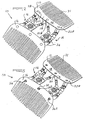
- Figures 1 to 5 show a hair clip 10 which has opposing first and second combs 12, 14 and a biasing member or structure 16 which is attached to, extends between and acts between the first and second combs 12, 14.
- the first comb 12 is made from any appropriate plastics material and is manufactured by way of injection moulding.
- the first comb 12 has a shoulder body 18 with an upper side 19 and an underside 20 and a plurality of spaced apart teeth 21 which extend from the shoulder 18.
- the exact shape and configuration of the shoulder 18 and teeth 21 are known and can vary depending on requirements.
- a plurality of spaced apart attachment brackets 22A, B, C are formed in the shoulder 18.
- the exact number of brackets 22 can vary depending on requirements. In this example the brackets 22 are identical and only one bracket 22 is described.
- the bracket 22 has a recess 24 in the underside 20 of the shoulder 18 and two spaced apart apertures 26A, B in the recess 24 and which extend through the body 18 between the underside 20 and the upper side 19.
- An insert 28 is engageable with the recess 24 and can be press-fitted into the recess 24 or can be glued to the body 18 in the recess 24 by way of any appropriate adhesive.
- the insert 28 is also made from any appropriate plastics material through an injection moulding process.
- the recess 24 can have any appropriate shape in plan and in this example is circular shaped in plan. Alternatively the recess can be oval, triangular or square shaped in plan.
- the number of apertures 26 can also vary but a minimum of two is required to form a bridge 30 between the adjacent apertures 26A, B.
- three or four apertures 26 can be formed in the recess 24 in order to accommodate various weaving patterns of the biasing member 16.
- the configuration of the apertures 26 can vary and can for example be configured in a semicircle, in a triangle or in a square.
- the biasing member 16 can consist of any appropriate elastic member which can pull the first and second combs 12, 14 towards one another in use.
- the biasing member 16 has an elastic tie 32 which is attached to the first and second combs 12, 14 by way of the brackets 22 and a number of ornamental beads 34 of various shapes and sizes which are trapped on the tie 32.
- the beads 34 provide ornamentation to the biasing member 16.
- the tie 32 enters each bracket 22 from the upper side 19 through one of the apertures 26A, passes through the aperture 26A into the recess 24, enters the second aperture 26B at the underside 20, passes through the second aperture 26B and exits the bracket 22 at the upper side 19.
- the bridge 30 traps the tie 32 on the bracket 22 between the apertures 26.
- the tie 32 thus forms loops through the apertures 26 and is freely movable through the apertures 26. This feature allows the biasing member 16 to balance itself between the combs 12, 14 to ensure that equal forces are exerted on the combs 12, 14 at each bracket 22.
- the ends of the tie 32 are tied in any appropriate way at a joint 36.
- the joint 36 is located inside a recess 24 and is covered by an insert 28.
- a knot can be formed in each end of the tie 32 which is larger than the apertures 26. The knot is thus trapped in the recess 24.
- the tie 32 does not protrude from the underside 20 and is hidden from view inside the recesses 24. On the upper side 19 the tie 32 is visible where it exits from the apertures 26.
- the clip 10 In use the clip 10 is inserted into a user's hair (not shown) in a known manner and grips the hair substantially in the form shown in Figure 1 .
- the teeth 21 pass through the hair and the shoulder 18 lies on top of the hair with the underside 20 facing towards the hair.
- the biasing member 16 lies on top of the hair and the upper side 19 faces away from the hair.
- the tie 32 As the tie 32 is not accessible on the underside 20 the tie 32 is protected from damage on the underside 20 and cannot tangle with the hair on the underside 20.
- Ties 32 of various lengths can be used during manufacturing which allows the design and manufacturing of biasing members 16 of different lengths between the combs 12, 14. In this manner clips 10 designed for different volumes of hair can be made. If required more than one tie 32 can be used to form the biasing member 16.
Abstract
Description
- This invention relates to a hair clip used in the styling and decoration of hair.
- A hair clip which consists of two opposing combs and an elastic which is attached to the two combs and which pulls the two combs together in use is known. The elastic often includes intricate beadwork to produce a decorative pattern between the two combs.
WO-A-2004/112532 discloses a hair clip that comprises two combs and at least one elastic member to bias the teeth of the combs towards each other in overlapping relationship. - The elastic is attached to the respective combs in various ways and sections of the elastic protrude from the underside of the respective combs.
- The protruding sections of the elastic are exposed to wear and tear and are easily damaged. This limits the working life of the hair clip.
- Additionally the protruding elastic can get caught on a user's hair which might cause damage to the user's hair and discomfort to the user.
- The protruding elastics further detract from the aesthetics of the hair clip.
- The invention aims to provide an alternative hair clip and comb used in such hair clip which might alleviate some of the aforementioned problems.
- The invention provides a hair clip which includes opposing first and second combs, each of which has a body with an upper side and an underside, a plurality of spaced apart teeth which extend from the body and a plurality of attachment means on the body, each of which has an individual recess formation on the underside and at least two spaced apart apertures which extend in the recess formation and between the underside and the upper side, and a biasing member which is attached to the first and second combs and which is engaged with the plurality of attachment means.
- The attachment means may include a bridge formation between the apertures. Preferably the attachment means includes an insert which is engageable with the recess formation. The insert may be press-fitted or adhesively attached to the recess formation. The insert may be cup-shaped in cross-section.
- The recess formation may have any shape in plan and can for example have a circular shape in plan.
- The attachment means may include three or more apertures and the apertures may be configured in any appropriate pattern such as a semicircular, triangular or square shape.
- The biasing member may include a tie member which extends between the first and second combs. The tie member is preferably elastic and passes through the apertures. The biasing member may include ornamentation on the tie member. The ornamentation is preferably in the form of beads of various shapes and sizes. The beads may be arranged on the tie member in a variety of patterns.
- The invention also provides a hair clip which includes opposing first and second combs, each of which has a body with an upper side and an underside, a plurality of spaced apart teeth which extend from the body and a plurality of attachment means on the body, each of which has an individual recess formation on the underside, at least two spaced apart apertures which extend in the recess formation and between the underside and the upper side and an insert which is engageable with the recess formation, and a biasing member which is attached to the plurality of attachment means on the first and second combs and which has an elastic tie member which passes through the apertures and ornamentation on the tie member.
- The invention further provides a comb for use in a hair clip of the aforementioned kind which has a body with an upper side and an underside, a plurality of spaced apart teeth which extend from the body, and a plurality of attachment means on the body, each of which has an individual recess formation on the underside and at least two spaced apart apertures which extend in the recess formation and between the underside and the upper side.
- The invention is further described by way of an example with reference to the accompanying drawings in which :
-
Figure 1 is a perspective view from above of a hair clip according to the invention in a closed position; -
Figure 2 is a perspective view of an underside of the clip ofFigure 1 in an open position; -
Figure 3 is a plan view from above of the clip ofFigure 1 in the open position ofFigure 2 ; -
Figure 4 is a view from below of the clip ofFigure 3 ; -
Figure 5 is a perspective view of the underside of the clip ofFigure 1 in the open position with inserts removed from attachment brackets on opposing combs of the clip; and -
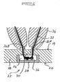
Figure 6 is a cross-sectional view of an attachment bracket used in the clip ofFigure 1 . -
Figures 1 to 5 show ahair clip 10 which has opposing first andsecond combs structure 16 which is attached to, extends between and acts between the first andsecond combs - Although the construction of the
individual combs identical combs first comb 12 is described. - The
first comb 12 is made from any appropriate plastics material and is manufactured by way of injection moulding. Thefirst comb 12 has ashoulder body 18 with anupper side 19 and anunderside 20 and a plurality of spaced apartteeth 21 which extend from theshoulder 18. The exact shape and configuration of theshoulder 18 andteeth 21 are known and can vary depending on requirements. - A plurality of spaced apart
attachment brackets 22A, B, C are formed in theshoulder 18. The exact number ofbrackets 22 can vary depending on requirements. In this example thebrackets 22 are identical and only onebracket 22 is described. - As is illustrated in
Figures 5 and6 thebracket 22 has arecess 24 in theunderside 20 of theshoulder 18 and two spaced apartapertures 26A, B in therecess 24 and which extend through thebody 18 between theunderside 20 and theupper side 19. - An
insert 28 is engageable with therecess 24 and can be press-fitted into therecess 24 or can be glued to thebody 18 in therecess 24 by way of any appropriate adhesive. - The
insert 28 is also made from any appropriate plastics material through an injection moulding process. - The
recess 24 can have any appropriate shape in plan and in this example is circular shaped in plan. Alternatively the recess can be oval, triangular or square shaped in plan. - The number of apertures 26 can also vary but a minimum of two is required to form a
bridge 30 between theadjacent apertures 26A, B. For example three or four apertures 26 can be formed in therecess 24 in order to accommodate various weaving patterns of thebiasing member 16. The configuration of the apertures 26 can vary and can for example be configured in a semicircle, in a triangle or in a square. - The
biasing member 16 can consist of any appropriate elastic member which can pull the first andsecond combs biasing member 16 has anelastic tie 32 which is attached to the first andsecond combs brackets 22 and a number ofornamental beads 34 of various shapes and sizes which are trapped on thetie 32. Thebeads 34 provide ornamentation to thebiasing member 16. - By using various weaving patterns, shapes and sizes of
beads 34, various techniques and different number and configurations of apertures 26 different shapes and configurations of biasingmembers 16 can be created. - The
tie 32 enters eachbracket 22 from theupper side 19 through one of theapertures 26A, passes through theaperture 26A into therecess 24, enters thesecond aperture 26B at theunderside 20, passes through thesecond aperture 26B and exits thebracket 22 at theupper side 19. Thebridge 30 traps thetie 32 on thebracket 22 between the apertures 26. Thetie 32 thus forms loops through the apertures 26 and is freely movable through the apertures 26. This feature allows thebiasing member 16 to balance itself between thecombs combs bracket 22. - The ends of the
tie 32 are tied in any appropriate way at ajoint 36. Thejoint 36 is located inside arecess 24 and is covered by aninsert 28. Alternatively to the joint 36 a knot can be formed in each end of thetie 32 which is larger than the apertures 26. The knot is thus trapped in therecess 24. - As the
joint 36 and knots are trapped in therecess 24 and covered by the insert 28 a neat finish of thebiasing member 16 andclip 10 is achieved. - Once all
inserts 28 are engaged with therecesses 24 thetie 32 does not protrude from theunderside 20 and is hidden from view inside therecesses 24. On theupper side 19 thetie 32 is visible where it exits from the apertures 26. - In use the
clip 10 is inserted into a user's hair (not shown) in a known manner and grips the hair substantially in the form shown inFigure 1 . Theteeth 21 pass through the hair and theshoulder 18 lies on top of the hair with theunderside 20 facing towards the hair. The biasingmember 16 lies on top of the hair and theupper side 19 faces away from the hair. As thetie 32 is not accessible on theunderside 20 thetie 32 is protected from damage on theunderside 20 and cannot tangle with the hair on theunderside 20. - Depending on finishing the
underside 20 of theshoulder 18 can be produced with a smooth and uniform surface which would enhance the aesthetic appeal of theclip 10. - As the joint 36 is trapped in the recess 24 a neat finish of the biasing
member 16 is achieved. - As the
tie 32 can move freely through at least some of thebrackets 22 it is not essential that the various crossovers of thetie 32 between thecombs member 16 and theclip 10.Ties 32 of various lengths can be used during manufacturing which allows the design and manufacturing of biasingmembers 16 of different lengths between thecombs tie 32 can be used to form the biasingmember 16.
Claims (10)
- A hair clip (10) which includes opposing first and second combs (12, 14), each of which has a body (18) with an upper side (19) and an underside (20), a plurality of spaced apart teeth (21) which extend from the body and a plurality of attachment means (22) on the body, a biasing member (16) which is attached to the first and second combs and which is engaged with the plurality of attachment means, each of the attachment means having an individual recess formation (24) on the underside and characterised in that at least two spaced apart apertures (26A, B) extend in the recess formation and between the underside and the upper side.
- A hair clip according to claim 1 characterised in that the attachment mean includes a bridge formation (30) between the apertures.
- A hair clip according to claim 1 or 2 characterised in that the attachment means includes an insert (28) which is engageable with the recess formation.
- A hair clip according to claim 3 characterised in that the insert is press-fitted or adhesively attached to the recess formation.
- A hair clip according to claim 3 or 4 characterised in that the insert is cup-shaped in cross-section.
- A hair clip according to any one of claims 1 to 5 characterised in that the biasing member includes a tie member (32) which extends between the first and second combs.
- A hair clip according to claim 6 characterised in that the tie member is preferably elastic and passes through the apertures.
- A hair clip according to claim 6 or 7 characterised in that the biasing member includes ornamentation (34) on the tie member.
- A hair clip according to claim 8 characterised in that the ornamentation is in the form of beads.
- A comb (12, 14) for use in a hair clip (10) according to any one of claims 1 to 9 which has a body (18) with an upper side (19) and an underside (20), a plurality of spaced apart teeth (21) which extend from the body and a plurality of attachment means (22) on the body, each of the attachment means having an individual recess formation (24) on the underside and characterised in that at least two spaced apart apertures (26A, B) extend in the recess formation and between the underside and the upper side.
Priority Applications (1)
| Application Number | Priority Date | Filing Date | Title |
|---|---|---|---|
| PL06827942T PL1947976T3 (en) | 2005-11-07 | 2006-11-02 | A hair clip |
Applications Claiming Priority (2)
| Application Number | Priority Date | Filing Date | Title |
|---|---|---|---|
| ZA200508995 | 2005-11-07 | ||
| PCT/ZA2006/000126 WO2007053861A1 (en) | 2005-11-07 | 2006-11-02 | A hair clip |
Publications (2)
| Publication Number | Publication Date |
|---|---|
| EP1947976A1 EP1947976A1 (en) | 2008-07-30 |
| EP1947976B1 true EP1947976B1 (en) | 2009-01-14 |
Family
ID=37673559
Family Applications (1)
| Application Number | Title | Priority Date | Filing Date |
|---|---|---|---|
| EP06827942A Not-in-force EP1947976B1 (en) | 2005-11-07 | 2006-11-02 | A hair clip |
Country Status (13)
| Country | Link |
|---|---|
| US (1) | US8047211B2 (en) |
| EP (1) | EP1947976B1 (en) |
| AT (1) | ATE420571T1 (en) |
| AU (1) | AU2006308545B2 (en) |
| CA (1) | CA2628568C (en) |
| DE (1) | DE602006004895D1 (en) |
| DK (1) | DK1947976T3 (en) |
| ES (1) | ES2322403T3 (en) |
| NZ (1) | NZ568318A (en) |
| PL (1) | PL1947976T3 (en) |
| PT (1) | PT1947976E (en) |
| WO (1) | WO2007053861A1 (en) |
| ZA (1) | ZA200803639B (en) |
Families Citing this family (11)
| Publication number | Priority date | Publication date | Assignee | Title |
|---|---|---|---|---|
| AU2008278680A1 (en) * | 2007-07-24 | 2009-01-29 | Richard George Gladwin | A comb |
| WO2010048634A1 (en) * | 2008-10-24 | 2010-04-29 | Sennits, Inc. | Improved hair comb and dual comb hair accessory having same |
| JP4343264B1 (en) * | 2009-03-26 | 2009-10-14 | 路秋 伊藤 | Hairdressing comb and hairdressing method |
| FR2958128B1 (en) * | 2010-04-02 | 2012-06-08 | Jeff Schwartz | HAIR CLIP |
| USD669632S1 (en) * | 2012-01-03 | 2012-10-23 | Sarah Baird | Dual hair comb |
| US9072355B1 (en) | 2013-05-30 | 2015-07-07 | Nicole Irene Magnani | Sharable hair accessory |
| USD776346S1 (en) | 2015-06-01 | 2017-01-10 | Nicole Irene Magnani | Multi-part joinable clip |
| US20190116953A1 (en) * | 2017-10-20 | 2019-04-25 | Brian Daly | Hair sectioning device |
| USD840099S1 (en) * | 2018-01-17 | 2019-02-05 | Janine Pretorius | Hair comb |
| USD1002941S1 (en) * | 2020-09-19 | 2023-10-24 | David Silva | Double comb hair holder |
| USD926373S1 (en) * | 2021-02-16 | 2021-07-27 | Janine Pretorius | Hair fastener |
Family Cites Families (28)
| Publication number | Priority date | Publication date | Assignee | Title |
|---|---|---|---|---|
| US613145A (en) * | 1898-10-25 | Setii watson herrick and caleb ramsey lunger | ||
| US1977920A (en) * | 1933-11-18 | 1934-10-23 | Robinson Jacqucline Crawford | Hair comb |
| US2384013A (en) * | 1944-06-23 | 1945-09-04 | Caldora Armand | Comb |
| US4327512A (en) * | 1980-12-11 | 1982-05-04 | Oliver Robert L | Identification device |
| US5174312A (en) * | 1991-11-12 | 1992-12-29 | Adams Joey M | Headwear apparatus |
| GB2316001B (en) * | 1996-08-09 | 2000-04-19 | Anthony Arthur Hawley | Hair styling apparatus |
| US6123086A (en) * | 1996-10-04 | 2000-09-26 | Kuglen; Francesca B. | Decorative hair accessory and method for providing |
| US5826593A (en) * | 1997-05-15 | 1998-10-27 | Haubrich; Joan M. | Hair retainer |
| US5735296A (en) * | 1997-05-19 | 1998-04-07 | Chen; Chin-Chin | Hair holder |
| US5803096A (en) * | 1997-12-29 | 1998-09-08 | Lee; Ya Chung | Hair clip |
| US5988184A (en) * | 1999-03-22 | 1999-11-23 | Shu; Ying Jen | Device for styling hair |
| US6311699B1 (en) * | 1999-12-02 | 2001-11-06 | Remedies Trading Corporation | Ponytail holder |
| US6453911B1 (en) * | 2001-05-16 | 2002-09-24 | David Alan Silva | Clip end hair fastener |
| US6691717B2 (en) * | 2001-05-16 | 2004-02-17 | David Alan Silva | Clip end hair fastener |
| USD483522S1 (en) * | 2002-10-11 | 2003-12-09 | July S. Leslie | Pair of connected hair combs |
| US7748390B2 (en) * | 2003-04-28 | 2010-07-06 | Sennits, Llc | Stretch comb hair retainer |
| ATE414438T1 (en) * | 2003-06-20 | 2008-12-15 | Thea Gladwin | HAIR CLIP WITH INTERLOCKING COMBS |
| WO2005025370A1 (en) * | 2003-09-15 | 2005-03-24 | Art C.D. S.A.R.L. | Hair clip comprising an elongating link |
| US6857216B1 (en) * | 2004-01-07 | 2005-02-22 | Scott Merin | Decoy anchor |
| USD532551S1 (en) * | 2004-01-22 | 2006-11-21 | Kuglen Francesca B | Hair retainer |
| USD510779S1 (en) * | 2004-03-16 | 2005-10-18 | Thea Gladwin | Hair fastener |
| USD511022S1 (en) * | 2004-04-23 | 2005-10-25 | Thea Gladwin | Hair fastener |
| USD509926S1 (en) * | 2004-04-23 | 2005-09-20 | Thea Gladwin | Hair fastener |
| US7278432B2 (en) * | 2004-06-04 | 2007-10-09 | Celebrity Signatures International, Inc. | Attachable/detachable supplemental hair accessory |
| US7753058B2 (en) * | 2004-11-16 | 2010-07-13 | Goody Products, Inc. | Hair retaining clip with elastic biasing member |
| USD597252S1 (en) * | 2007-05-31 | 2009-07-28 | Janine Pretorius | Hair fastener |
| AU2008278680A1 (en) * | 2007-07-24 | 2009-01-29 | Richard George Gladwin | A comb |
| WO2010048634A1 (en) * | 2008-10-24 | 2010-04-29 | Sennits, Inc. | Improved hair comb and dual comb hair accessory having same |
-
2006
- 2006-11-02 PT PT06827942T patent/PT1947976E/en unknown
- 2006-11-02 US US12/092,955 patent/US8047211B2/en active Active
- 2006-11-02 DE DE602006004895T patent/DE602006004895D1/en active Active
- 2006-11-02 DK DK06827942T patent/DK1947976T3/en active
- 2006-11-02 ES ES06827942T patent/ES2322403T3/en active Active
- 2006-11-02 NZ NZ568318A patent/NZ568318A/en not_active IP Right Cessation
- 2006-11-02 AT AT06827942T patent/ATE420571T1/en active IP Right Revival
- 2006-11-02 AU AU2006308545A patent/AU2006308545B2/en not_active Ceased
- 2006-11-02 PL PL06827942T patent/PL1947976T3/en unknown
- 2006-11-02 WO PCT/ZA2006/000126 patent/WO2007053861A1/en active Application Filing
- 2006-11-02 EP EP06827942A patent/EP1947976B1/en not_active Not-in-force
- 2006-11-02 CA CA2628568A patent/CA2628568C/en not_active Expired - Fee Related
-
2008
- 2008-04-24 ZA ZA200803639A patent/ZA200803639B/en unknown
Also Published As
| Publication number | Publication date |
|---|---|
| AU2006308545A1 (en) | 2007-05-10 |
| NZ568318A (en) | 2010-07-30 |
| US8047211B2 (en) | 2011-11-01 |
| DE602006004895D1 (en) | 2009-03-05 |
| US20080283074A1 (en) | 2008-11-20 |
| ES2322403T3 (en) | 2009-06-19 |
| PT1947976E (en) | 2009-04-14 |
| PL1947976T3 (en) | 2009-07-31 |
| CA2628568C (en) | 2012-04-24 |
| ATE420571T1 (en) | 2009-01-15 |
| ZA200803639B (en) | 2009-02-25 |
| DK1947976T3 (en) | 2009-05-04 |
| CA2628568A1 (en) | 2007-05-10 |
| AU2006308545B2 (en) | 2010-07-22 |
| WO2007053861A1 (en) | 2007-05-10 |
| EP1947976A1 (en) | 2008-07-30 |
Similar Documents
| Publication | Publication Date | Title |
|---|---|---|
| EP1947976B1 (en) | A hair clip | |
| CA117269S (en) | Gliding door handle assembly | |
| USD924096S1 (en) | Decorative element of jewelry | |
| EP2440081A2 (en) | Hair addition for providing bump up effect | |
| US5655272A (en) | Scarf cinch | |
| USD614863S1 (en) | Child's backpack | |
| US5099552A (en) | Lace decorating device | |
| USD614398S1 (en) | Child's backpack | |
| USD527843S1 (en) | Hair dye comb | |
| US8082930B2 (en) | Hair clip with tines extending parallel to the enveloped hair | |
| US20100192967A1 (en) | Comb | |
| CA105197S (en) | Package for tooth whitening system | |
| US6325074B1 (en) | Hair clip having jaw for accommodating ornaments | |
| CN206079328U (en) | Can rock ornament | |
| CA107262S (en) | Fencing wire end clip | |
| USD519155S1 (en) | Doll-shaped bookmark | |
| KR200361988Y1 (en) | the accessories which can express initial | |
| KR20110003353U (en) | Hair band | |
| KR200239136Y1 (en) | Hair pin | |
| USD614399S1 (en) | Child's backpack | |
| JP6112690B1 (en) | Cloth body fastener | |
| KR200455823Y1 (en) | Adornment member for accessory | |
| KR200202777Y1 (en) | Hair accessories | |
| CN201393665Y (en) | Hair fastener with bead belt | |
| CN2377901Y (en) | Elastic decorative hairpin |
Legal Events
| Date | Code | Title | Description |
|---|---|---|---|
| PUAI | Public reference made under article 153(3) epc to a published international application that has entered the european phase |
Free format text: ORIGINAL CODE: 0009012 |
|
| 17P | Request for examination filed |
Effective date: 20080414 |
|
| AK | Designated contracting states |
Kind code of ref document: A1 Designated state(s): AT BE BG CH CY CZ DE DK EE ES FI FR GB GR HU IE IS IT LI LT LU LV MC NL PL PT RO SE SI SK TR |
|
| GRAP | Despatch of communication of intention to grant a patent |
Free format text: ORIGINAL CODE: EPIDOSNIGR1 |
|
| DAX | Request for extension of the european patent (deleted) | ||
| GRAS | Grant fee paid |
Free format text: ORIGINAL CODE: EPIDOSNIGR3 |
|
| GRAA | (expected) grant |
Free format text: ORIGINAL CODE: 0009210 |
|
| AK | Designated contracting states |
Kind code of ref document: B1 Designated state(s): AT BE BG CH CY CZ DE DK EE ES FI FR GB GR HU IE IS IT LI LT LU LV MC NL PL PT RO SE SI SK TR |
|
| REG | Reference to a national code |
Ref country code: GB Ref legal event code: FG4D |
|
| REG | Reference to a national code |
Ref country code: CH Ref legal event code: EP |
|
| REG | Reference to a national code |
Ref country code: IE Ref legal event code: FG4D |
|
| REF | Corresponds to: |
Ref document number: 602006004895 Country of ref document: DE Date of ref document: 20090305 Kind code of ref document: P |
|
| REG | Reference to a national code |
Ref country code: PT Ref legal event code: SC4A Free format text: AVAILABILITY OF NATIONAL TRANSLATION Effective date: 20090406 |
|
| REG | Reference to a national code |
Ref country code: DK Ref legal event code: T3 |
|
| REG | Reference to a national code |
Ref country code: GR Ref legal event code: EP Ref document number: 20090401073 Country of ref document: GR |
|
| NLUE | Nl: licence registered with regard to european patents |
Effective date: 20090417 |
|
| REG | Reference to a national code |
Ref country code: ES Ref legal event code: FG2A Ref document number: 2322403 Country of ref document: ES Kind code of ref document: T3 |
|
| PG25 | Lapsed in a contracting state [announced via postgrant information from national office to epo] |
Ref country code: LT Free format text: LAPSE BECAUSE OF FAILURE TO SUBMIT A TRANSLATION OF THE DESCRIPTION OR TO PAY THE FEE WITHIN THE PRESCRIBED TIME-LIMIT Effective date: 20090114 Ref country code: FI Free format text: LAPSE BECAUSE OF FAILURE TO SUBMIT A TRANSLATION OF THE DESCRIPTION OR TO PAY THE FEE WITHIN THE PRESCRIBED TIME-LIMIT Effective date: 20090114 Ref country code: SI Free format text: LAPSE BECAUSE OF FAILURE TO SUBMIT A TRANSLATION OF THE DESCRIPTION OR TO PAY THE FEE WITHIN THE PRESCRIBED TIME-LIMIT Effective date: 20090114 |
|
| REG | Reference to a national code |
Ref country code: PL Ref legal event code: T3 |
|
| PG25 | Lapsed in a contracting state [announced via postgrant information from national office to epo] |
Ref country code: AT Free format text: LAPSE BECAUSE OF FAILURE TO SUBMIT A TRANSLATION OF THE DESCRIPTION OR TO PAY THE FEE WITHIN THE PRESCRIBED TIME-LIMIT Effective date: 20090114 Ref country code: LV Free format text: LAPSE BECAUSE OF FAILURE TO SUBMIT A TRANSLATION OF THE DESCRIPTION OR TO PAY THE FEE WITHIN THE PRESCRIBED TIME-LIMIT Effective date: 20090114 Ref country code: IS Free format text: LAPSE BECAUSE OF FAILURE TO SUBMIT A TRANSLATION OF THE DESCRIPTION OR TO PAY THE FEE WITHIN THE PRESCRIBED TIME-LIMIT Effective date: 20090514 Ref country code: SE Free format text: LAPSE BECAUSE OF FAILURE TO SUBMIT A TRANSLATION OF THE DESCRIPTION OR TO PAY THE FEE WITHIN THE PRESCRIBED TIME-LIMIT Effective date: 20090414 |
|
| PG25 | Lapsed in a contracting state [announced via postgrant information from national office to epo] |
Ref country code: CZ Free format text: LAPSE BECAUSE OF FAILURE TO SUBMIT A TRANSLATION OF THE DESCRIPTION OR TO PAY THE FEE WITHIN THE PRESCRIBED TIME-LIMIT Effective date: 20090114 Ref country code: EE Free format text: LAPSE BECAUSE OF FAILURE TO SUBMIT A TRANSLATION OF THE DESCRIPTION OR TO PAY THE FEE WITHIN THE PRESCRIBED TIME-LIMIT Effective date: 20090114 |
|
| PGRI | Patent reinstated in contracting state [announced from national office to epo] |
Ref country code: AT Effective date: 20090811 |
|
| PLBE | No opposition filed within time limit |
Free format text: ORIGINAL CODE: 0009261 |
|
| STAA | Information on the status of an ep patent application or granted ep patent |
Free format text: STATUS: NO OPPOSITION FILED WITHIN TIME LIMIT |
|
| PG25 | Lapsed in a contracting state [announced via postgrant information from national office to epo] |
Ref country code: SK Free format text: LAPSE BECAUSE OF FAILURE TO SUBMIT A TRANSLATION OF THE DESCRIPTION OR TO PAY THE FEE WITHIN THE PRESCRIBED TIME-LIMIT Effective date: 20090114 Ref country code: RO Free format text: LAPSE BECAUSE OF FAILURE TO SUBMIT A TRANSLATION OF THE DESCRIPTION OR TO PAY THE FEE WITHIN THE PRESCRIBED TIME-LIMIT Effective date: 20090114 |
|
| 26N | No opposition filed |
Effective date: 20091015 |
|
| PGRI | Patent reinstated in contracting state [announced from national office to epo] |
Ref country code: AT Effective date: 20090811 |
|
| PG25 | Lapsed in a contracting state [announced via postgrant information from national office to epo] |
Ref country code: BG Free format text: LAPSE BECAUSE OF FAILURE TO SUBMIT A TRANSLATION OF THE DESCRIPTION OR TO PAY THE FEE WITHIN THE PRESCRIBED TIME-LIMIT Effective date: 20090414 |
|
| PGFP | Annual fee paid to national office [announced via postgrant information from national office to epo] |
Ref country code: AT Payment date: 20091120 Year of fee payment: 4 |
|
| PG25 | Lapsed in a contracting state [announced via postgrant information from national office to epo] |
Ref country code: MC Free format text: LAPSE BECAUSE OF NON-PAYMENT OF DUE FEES Effective date: 20091130 |
|
| PGFP | Annual fee paid to national office [announced via postgrant information from national office to epo] |
Ref country code: PL Payment date: 20101026 Year of fee payment: 5 |
|
| PGFP | Annual fee paid to national office [announced via postgrant information from national office to epo] |
Ref country code: IT Payment date: 20101124 Year of fee payment: 5 Ref country code: GR Payment date: 20101123 Year of fee payment: 5 |
|
| PG25 | Lapsed in a contracting state [announced via postgrant information from national office to epo] |
Ref country code: LU Free format text: LAPSE BECAUSE OF NON-PAYMENT OF DUE FEES Effective date: 20091102 |
|
| PG25 | Lapsed in a contracting state [announced via postgrant information from national office to epo] |
Ref country code: HU Free format text: LAPSE BECAUSE OF FAILURE TO SUBMIT A TRANSLATION OF THE DESCRIPTION OR TO PAY THE FEE WITHIN THE PRESCRIBED TIME-LIMIT Effective date: 20090715 |
|
| PG25 | Lapsed in a contracting state [announced via postgrant information from national office to epo] |
Ref country code: TR Free format text: LAPSE BECAUSE OF FAILURE TO SUBMIT A TRANSLATION OF THE DESCRIPTION OR TO PAY THE FEE WITHIN THE PRESCRIBED TIME-LIMIT Effective date: 20090114 |
|
| PG25 | Lapsed in a contracting state [announced via postgrant information from national office to epo] |
Ref country code: CY Free format text: LAPSE BECAUSE OF FAILURE TO SUBMIT A TRANSLATION OF THE DESCRIPTION OR TO PAY THE FEE WITHIN THE PRESCRIBED TIME-LIMIT Effective date: 20090114 |
|
| PGFP | Annual fee paid to national office [announced via postgrant information from national office to epo] |
Ref country code: ES Payment date: 20111123 Year of fee payment: 6 Ref country code: FR Payment date: 20111125 Year of fee payment: 6 Ref country code: DK Payment date: 20111124 Year of fee payment: 6 Ref country code: CH Payment date: 20111124 Year of fee payment: 6 Ref country code: NL Payment date: 20111123 Year of fee payment: 6 Ref country code: PT Payment date: 20111024 Year of fee payment: 6 |
|
| PGFP | Annual fee paid to national office [announced via postgrant information from national office to epo] |
Ref country code: IE Payment date: 20121120 Year of fee payment: 7 |
|
| REG | Reference to a national code |
Ref country code: PT Ref legal event code: MM4A Free format text: LAPSE DUE TO NON-PAYMENT OF FEES Effective date: 20130502 |
|
| REG | Reference to a national code |
Ref country code: NL Ref legal event code: V1 Effective date: 20130601 |
|
| REG | Reference to a national code |
Ref country code: CH Ref legal event code: PL |
|
| REG | Reference to a national code |
Ref country code: DK Ref legal event code: EBP |
|
| REG | Reference to a national code |
Ref country code: AT Ref legal event code: MM01 Ref document number: 420571 Country of ref document: AT Kind code of ref document: T Effective date: 20121102 |
|
| PG25 | Lapsed in a contracting state [announced via postgrant information from national office to epo] |
Ref country code: CH Free format text: LAPSE BECAUSE OF NON-PAYMENT OF DUE FEES Effective date: 20121130 Ref country code: LI Free format text: LAPSE BECAUSE OF NON-PAYMENT OF DUE FEES Effective date: 20121130 Ref country code: AT Free format text: LAPSE BECAUSE OF FAILURE TO SUBMIT A TRANSLATION OF THE DESCRIPTION OR TO PAY THE FEE WITHIN THE PRESCRIBED TIME-LIMIT Effective date: 20121102 |
|
| REG | Reference to a national code |
Ref country code: FR Ref legal event code: ST Effective date: 20130731 |
|
| PG25 | Lapsed in a contracting state [announced via postgrant information from national office to epo] |
Ref country code: IT Free format text: LAPSE BECAUSE OF NON-PAYMENT OF DUE FEES Effective date: 20121102 Ref country code: GR Free format text: LAPSE BECAUSE OF NON-PAYMENT OF DUE FEES Effective date: 20130604 Ref country code: NL Free format text: LAPSE BECAUSE OF NON-PAYMENT OF DUE FEES Effective date: 20130601 Ref country code: PT Free format text: LAPSE BECAUSE OF NON-PAYMENT OF DUE FEES Effective date: 20130502 |
|
| REG | Reference to a national code |
Ref country code: GR Ref legal event code: ML Ref document number: 20090401073 Country of ref document: GR Effective date: 20130604 |
|
| PG25 | Lapsed in a contracting state [announced via postgrant information from national office to epo] |
Ref country code: DK Free format text: LAPSE BECAUSE OF NON-PAYMENT OF DUE FEES Effective date: 20121130 |
|
| PG25 | Lapsed in a contracting state [announced via postgrant information from national office to epo] |
Ref country code: FR Free format text: LAPSE BECAUSE OF NON-PAYMENT OF DUE FEES Effective date: 20121130 |
|
| PG25 | Lapsed in a contracting state [announced via postgrant information from national office to epo] |
Ref country code: PL Free format text: LAPSE BECAUSE OF NON-PAYMENT OF DUE FEES Effective date: 20121102 |
|
| REG | Reference to a national code |
Ref country code: PL Ref legal event code: LAPE |
|
| REG | Reference to a national code |
Ref country code: ES Ref legal event code: FD2A Effective date: 20140527 |
|
| PG25 | Lapsed in a contracting state [announced via postgrant information from national office to epo] |
Ref country code: ES Free format text: LAPSE BECAUSE OF NON-PAYMENT OF DUE FEES Effective date: 20121103 |
|
| REG | Reference to a national code |
Ref country code: IE Ref legal event code: MM4A |
|
| PG25 | Lapsed in a contracting state [announced via postgrant information from national office to epo] |
Ref country code: IE Free format text: LAPSE BECAUSE OF NON-PAYMENT OF DUE FEES Effective date: 20131102 |
|
| PGFP | Annual fee paid to national office [announced via postgrant information from national office to epo] |
Ref country code: DE Payment date: 20141130 Year of fee payment: 9 Ref country code: GB Payment date: 20141120 Year of fee payment: 9 |
|
| PGFP | Annual fee paid to national office [announced via postgrant information from national office to epo] |
Ref country code: BE Payment date: 20141125 Year of fee payment: 9 |
|
| REG | Reference to a national code |
Ref country code: DE Ref legal event code: R119 Ref document number: 602006004895 Country of ref document: DE |
|
| GBPC | Gb: european patent ceased through non-payment of renewal fee |
Effective date: 20151102 |
|
| PG25 | Lapsed in a contracting state [announced via postgrant information from national office to epo] |
Ref country code: DE Free format text: LAPSE BECAUSE OF NON-PAYMENT OF DUE FEES Effective date: 20160601 Ref country code: GB Free format text: LAPSE BECAUSE OF NON-PAYMENT OF DUE FEES Effective date: 20151102 |
|
| PG25 | Lapsed in a contracting state [announced via postgrant information from national office to epo] |
Ref country code: BE Free format text: LAPSE BECAUSE OF NON-PAYMENT OF DUE FEES Effective date: 20151130 |