EP1947842A2 - Image sensors with blooming reduction mechanisms - Google Patents
Image sensors with blooming reduction mechanisms Download PDFInfo
- Publication number
- EP1947842A2 EP1947842A2 EP07150484A EP07150484A EP1947842A2 EP 1947842 A2 EP1947842 A2 EP 1947842A2 EP 07150484 A EP07150484 A EP 07150484A EP 07150484 A EP07150484 A EP 07150484A EP 1947842 A2 EP1947842 A2 EP 1947842A2
- Authority
- EP
- European Patent Office
- Prior art keywords
- pixels
- row
- rows
- exposure period
- exposing
- Prior art date
- Legal status (The legal status is an assumption and is not a legal conclusion. Google has not performed a legal analysis and makes no representation as to the accuracy of the status listed.)
- Granted
Links
Images




Classifications
-
- H—ELECTRICITY
- H10—SEMICONDUCTOR DEVICES; ELECTRIC SOLID-STATE DEVICES NOT OTHERWISE PROVIDED FOR
- H10F—INORGANIC SEMICONDUCTOR DEVICES SENSITIVE TO INFRARED RADIATION, LIGHT, ELECTROMAGNETIC RADIATION OF SHORTER WAVELENGTH OR CORPUSCULAR RADIATION
- H10F39/00—Integrated devices, or assemblies of multiple devices, comprising at least one element covered by group H10F30/00, e.g. radiation detectors comprising photodiode arrays
- H10F39/10—Integrated devices
- H10F39/12—Image sensors
- H10F39/18—Complementary metal-oxide-semiconductor [CMOS] image sensors; Photodiode array image sensors
- H10F39/186—Complementary metal-oxide-semiconductor [CMOS] image sensors; Photodiode array image sensors having arrangements for blooming suppression
-
- H—ELECTRICITY
- H04—ELECTRIC COMMUNICATION TECHNIQUE
- H04N—PICTORIAL COMMUNICATION, e.g. TELEVISION
- H04N25/00—Circuitry of solid-state image sensors [SSIS]; Control thereof
-
- H—ELECTRICITY
- H04—ELECTRIC COMMUNICATION TECHNIQUE
- H04N—PICTORIAL COMMUNICATION, e.g. TELEVISION
- H04N25/00—Circuitry of solid-state image sensors [SSIS]; Control thereof
- H04N25/50—Control of the SSIS exposure
- H04N25/53—Control of the integration time
- H04N25/533—Control of the integration time by using differing integration times for different sensor regions
-
- H—ELECTRICITY
- H04—ELECTRIC COMMUNICATION TECHNIQUE
- H04N—PICTORIAL COMMUNICATION, e.g. TELEVISION
- H04N25/00—Circuitry of solid-state image sensors [SSIS]; Control thereof
- H04N25/50—Control of the SSIS exposure
- H04N25/57—Control of the dynamic range
- H04N25/58—Control of the dynamic range involving two or more exposures
- H04N25/587—Control of the dynamic range involving two or more exposures acquired sequentially, e.g. using the combination of odd and even image fields
- H04N25/589—Control of the dynamic range involving two or more exposures acquired sequentially, e.g. using the combination of odd and even image fields with different integration times, e.g. short and long exposures
-
- H—ELECTRICITY
- H04—ELECTRIC COMMUNICATION TECHNIQUE
- H04N—PICTORIAL COMMUNICATION, e.g. TELEVISION
- H04N25/00—Circuitry of solid-state image sensors [SSIS]; Control thereof
- H04N25/60—Noise processing, e.g. detecting, correcting, reducing or removing noise
- H04N25/62—Detection or reduction of noise due to excess charges produced by the exposure, e.g. smear, blooming, ghost image, crosstalk or leakage between pixels
- H04N25/621—Detection or reduction of noise due to excess charges produced by the exposure, e.g. smear, blooming, ghost image, crosstalk or leakage between pixels for the control of blooming
- H04N25/623—Detection or reduction of noise due to excess charges produced by the exposure, e.g. smear, blooming, ghost image, crosstalk or leakage between pixels for the control of blooming by evacuation via the output or reset lines
Definitions
- the present disclosure relates to image sensors having blooming reduction mechanisms.
- aspects of the present disclosure relate to complementary metal oxide silicon (CMOS) image sensors having increased dynamic range and reduced blooming characteristics.
- CMOS complementary metal oxide silicon
- image sensors Unlike traditional cameras that use films to capture and store images, today's digital cameras use solid-state image sensors to acquire images. Such image sensors are typically disposed on fingernail-sized silicon chips containing millions of photoelectric devices such as photodiodes arranged in an array of pixels. During exposure, each photoelectric device records intensity or brightness of an incident light by converting optical energy into accumulated electrical charges. The brightness recorded by each photoelectric device can then be read out and stored as digital signals.
- Dynamic range is the ratio of maximum and minimum light intensities that an image sensor can capture.
- the charge holding capacity of each photoelectric device in the image sensor typically determines its dynamic range.
- the limited capacity of each photoelectric device limits the image sensor's ability to capture bright and dark subjects at the same time. As a result, if a long exposure is used to capture dark subjects, bright subjects can lose contrast and become a bright spot. If a short exposure is used to capture bright subjects, dark subjects can blend into a dark background and simply disappear.
- Blooming occurs when a photoelectric device of the image sensor overflows and spills accumulated charges (e.g., electrons) into neighboring photoelectric devices.
- the spilled can distort the brightness recorded by the neighboring photoelectric devices and ultimately reduce spatial resolution.
- the brightness recorded by a neighboring photoelectric device can be falsely high due to the spilled charges.
- the bright subjects causing blooming often appear to have a "glow" around them in a captured image.
- Figure 1 is a schematic diagram of an image sensor configured in accordance with an embodiment of the invention.
- Figure 2 is a schematic diagram of a pixel suitable for use in the image sensor of Figure 1 and configured in accordance with the invention.
- Figure 3 is a functional diagram of logic modules of a timing and control circuit configured in accordance with an embodiment of the invention.
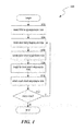
- Figure 4 is a flow diagram showing a method for operating an image sensor configured in accordance with an embodiment of the invention.
- Figure 5 is a schematic diagram of an image sensor configured in accordance with another embodiment of the invention.
- Figure 6 is a schematic diagram of an image sensor configured in accordance with a further embodiment of the invention.
- Figure 7 is a flow diagram showing a method for operating the image sensor of Figure 5 .
- FIG. 1 schematically illustrates an image sensor 100 with a blooming reduction mechanism and configured in accordance with an embodiment of the invention.
- the image sensor 100 can include a pixel array 101, a column-select circuit 106, a row-select circuit 108, analog signal processors 104, a timing and control circuit 110, an A/D converter 112, and a digital signal processor (DSP) 114. These components can be disposed on a single substrate 103 (e.g., a semiconductor chip) or can be disposed on multiple substrates.
- a single substrate 103 e.g., a semiconductor chip
- the pixel array 10 can include a plurality of pixels 102 arranged in columns and rows.
- the pixel array 101 includes six columns and six rows designated rows L0, S0, L1, S1, L2, and S2 and columns I to 6.
- row L0 includes pixels L00-L05
- row S0 includes pixels S00-S05.
- the pixels in rows L0, L1, and L2 are configured for a long exposure period (e.g., 2 seconds), and those in rows S0, S1, and S2 are configured for a short exposure period (e.g., 0.1 seconds).
- rows L0, L1, and L2 are referred to as long exposure rows
- rows S0, S1, and S2 are referred to as short exposure rows hereinafter.
- Individual pixels 102 can be configured as a charged coupled device, a CMOS passive pixel sensor, a CMOS active pixel sensor, or other types of light sensors.
- the pixels 102 can be configured as 4T CMOS active pixels as described in more detail below with reference to Figure 2 .
- the pixels 102 in the long exposure rows are configured to be generally identical to those in the short exposure rows.
- the pixels 102 in the long exposure rows can be configured to be different than those in the short exposure rows.
- the pixels 102 in rows L0, L1, and L2 can include photosites having a larger well capacity than those in rows S0, S1, and S2,
- the timing and control circuit 110 can include a microprocessor-based processor 111 containing logic modules for monitoring and controlling the exposure and readout sequence of the pixels 102.
- the processor 111 can include an 8080, 8085, 8086, or other type of logic processor produced by Intel, Corp. of Santa Clara, California.
- the timing and control circuit 110 can also include logic modules configured to reduce overexposure blooming by varying the exposure and readout sequence of the pixels 102, as described in more detail below with reference to Figure 2 .
- the column-select circuit 106 and the row-select circuit 108 can include solid-state switches including, for example, metal oxide silicon (MOS), CMOS, or other types of solid-state switch.
- MOS metal oxide silicon
- CMOS complementary metal oxide silicon
- the column-select circuit 106 and the row-select circuit 108 can decode signals sampled from the pixels 102 by selectively enabling output from each column and row of the pixels 102.
- the analog signal processors 104 and/or the digital signal processor 114 can include input clamping, sampling, amplifying, multiplexing, filtering, or other types of circuits.
- the analog signal processors 104 can include source-follower transistors for amplifying sampled signals from the pixels 102
- the digital signal processor 114 can include a data compression circuit.
- the A/D converter 112 can include conversion circuits that convert analog signals from the pixels 102 into digital signals having a desired resolution (e.g., 8-bit, 16-bit, 32-bit, etc.)
- the timing and control circuit 110 controls exposure of individual rows of the pixel array 101 to an incident light by selectively turning on/off the row-select circuit 108 and the column-select circuit 106.
- the individual rows of the pixel array 101 can be exposed for different exposure periods. For example, rows L0, L1, and L2 are exposed for a long exposure period (e.g., 2 seconds), and rows S0, S1, and S2 are exposed for a short exposure period (e.g., 0.1 seconds).
- the pixels 102 convert the incident light into accumulated charges (e.g., electrons). Then the pixels 102 are sampled to generate analog output signals based on the amount of accumulated charges.
- the analog signal processors 104 then process the analog output signals before the A/D converter 112 converts them into digital output signals.
- the digital signal processor 114 then further processes the digital output signals into final output signals that can be displayed on a monitor or printed as a photo.
- One expected advantage of having different exposure periods for different rows of pixels 102 is the improved dynamic range of the image sensor 100.
- dark subjects can be clearly captured.
- another adjacent row of the pixels has a short period, bright can be captured.
- the captured dark and bright subjects can then be combined using histogram equalizing, weighted averaging, contrast blending, radiance mapping, or another suitable technique to derive a final image.
- the image would have details for both the dark and bright subjects to improve the dynamic range of the image sensor 100.
- Figure 2 illustrates a pixel 102 suitable for use in the image sensor 100 of Figure 1 .
- the pixel 102 includes a photodiode 122 connected to a floating node 126 via a transfer transistor 124.
- the floating node 126 in turn is connected to a source-follower transistor 128 that can buffer a signal from the floating node 126.
- the output from the source-follower transistor 128 is connected to a column bitline 136 via a row-select transistor 130.
- the floating node 126 is also electrically connected to a reset transistor 132 whose source is connected to a reference voltage line 134 at a reference voltage V dd .
- the pixel 102 is configured as a four-transistor (4T) CMOS active pixel. In other embodiments, the pixel 102 can be configured as a 3T, 5T, 6T. or 7T CMOS or as a CCD pixel.
- 4T four-transistor
- the pixel 102 can be configured as a 3T, 5T, 6T. or 7T CMOS or as a CCD pixel.
- the reset transistor 132 is first turned on to set the floating node 126 to the reference voltage V dd , Then the transfer transistor 124 is turned on to transfer the accumulated charges from the photodiode 122 to the floating node 126. As a result, the floating node 126 acquires a new voltage, and the photodiode 122 is reset. The source-follower transistor 128 then buffers the new voltage at the floating node 126 onto the column bitline 136. In certain embodiments, before the photodiode 122 is exposed to an incident light, the transfer transistor 124 and the reset transistor 132 can be turned on to reset the photodiode 122.
- FIG. 3 illustrates a functional diagram showing logic modules 200 of the timing and control circuit 110 suitable for use in the image sensor 100.
- Each module can be a computer program, procedure, or process written as source code in a conventional programming language, such as the C++ programming language, and can be presented for execution by the processor 111 of the timing and control circuit 110.
- Each module can also be implemented as individual electrical circuits.
- the various implementations of the source code and object and byte codes can be stored on a computer-readable storage medium or embodied on a transmission medium in a carrier wave.
- the modules of the timing and control circuit 110 can include an input module 204, a storage module 206, an exposure control module 208, a readout module 210, and a monitoring module 212.
- the input module 204 accepts input, such as pixel readings 222 (e.g., pixel output voltage), and communicates the accepted information to other components for further processing.
- the storage module 206 organizes records including, for example, operating parameters 216, and facilitates storing and retrieving of these records to and from a storage 214 (e.g., a flash memory module, an EPROM, or other storage device). Any type of record organization can be utilized, including a flat file system, hierarchical database, relational database, or distributed database.
- the exposure control module 208 can control an exposure sequence of the pixels 102 by, for example, causing each row of pixels 102 to be exposed to an incident light sequentially. For instance, the exposure control module 208 can cause row L0 to be exposed before row S0 is exposed, or can cause row L0 and S0 to be exposed at the same time. In one embodiment, the exposure control module 208 can also implement asynchronous sequential exposure of the long exposure rows and the short exposure rows. For example, the long exposure rows can be exposed sequentially starting from a time To. After a preset time period AT, the short exposure rows are exposed sequentially. In other embodiments, the exposure control module 208 can implement synchronous sequential exposure of the long and short exposure rows, For example, the short exposure rows can be exposed only after all the long exposure rows have been exposed.
- the readout module 210 can control a readout sequence of the pixels 102 by, for example, sending output signals 224 to the column-select and row-select circuits 106, 108,
- the readout module 210 can be configured to scan each row of the pixel array 101 sequentially.
- the readout module 210 can cause the rows to be scanned in a regular scanning sequence as follows: L0,S0,L1,S1,L2,S2
- the readout module 210 can be configured to scan short exposure rows preferentially before scanning long exposure rows to reduce scanning/exposure time.
- the readout module 210 can be configured to repeatedly scan a particular row in a single scanning sequence, as described in more detail below with reference to Figure 6 .
- the monitoring module 212 can control variables based on the pixel readings 222. For example, the monitoring module 212 can compare the pixel readings 222 (e.g., sensed light intensity) of the pixels 102 ( Figure 1 ) to a preset threshold value to determine whether the pixels 102 are overexposed. If the sensed light intensity exceeds the preset threshold value, the monitoring module 212 indicates overexposure, and the readout and/or exposure control modules 210, 208 can modify the readout and/or exposure sequence to reduce the blooming effect. For example, if the monitoring module 212 indicates that there is no overexposure, then the regular scanning sequence can be used; otherwise, an overexposure readout sequence can be used, as described in more detail below with reference to Figure 4 .
- the regular scanning sequence can be used; otherwise, an overexposure readout sequence can be used, as described in more detail below with reference to Figure 4 .
- Figure 4 illustrates a flow diagram showing a method 300 for operating the image sensor 100 of Figure 1 for blooming reduction.
- the first long exposure row L0 can be read out after row L0 has been exposed for a first exposure period (block 302).
- reading the pixels 102 of row L0 can include turning on the transfer transistor 124 to transfer accumulated charges from the photodiode 122 to the floating node 126.
- the photodiode 122 is now reset (i.e., having a voltage generally equal to a reference voltage).
- the successive long exposure row i.e, row L1
- Row L1 can be exposed generally simultaneously as the row L0 or can be exposed after row L0 has been read out.
- the photodiode 122 of each pixel 102 in row L 1 is also reset.
- the first successive short exposure row i.e., row S0
- the first successive short exposure row i.e., row S0
- the first successive short exposure row i.e, row S0
- the pixels 102 in row S0 can be read out (block 310).
- decision block 312 if there are more rows in the pixel array 101, then the process returns to block 304, and the remaining rows of pixels can be scanned in a scanning sequence as follows: L0,L1,S0,L2,S1,L3,S2 Otherwise, the process ends.
- One expected advantage of operating the image sensor 100 according to the process of Figure 4 is the reduced blooming potential of the pixels 102.
- rows L0 and L1 are long exposure rows, so the pixels 102 in these rows have a greater potential for blooming than those in short exposure rows S0, S1, and S2. Blooming of any pixel 102 in rows L0 and L1 can affect the short row S0 row S0 is adjacent to both row L0 and row L1.
- any spilled-over charges can be destroyed.
- the impact of any blooming in the long exposure rows L0 and L1 can be at least reduced.
- the dynamic range of the image sensor 100 can be increased.
- Another expected advantage of several embodiments of the illustrated process of Figure 4 is that the image quality produced by the image sensor 100 is not affected during normal dynamic range operations.
- the image sensor 100 in Figure 1 is illustrated as having pixels arranged in long and short exposure rows, in another embodiment, the image sensor 100 can include pixel subsets that have pixels located in different rows and/or columns as illustrated in Figure 5 .
- the image sensor 100 includes long exposure subsets L0, L1, and L2 and short exposure subsets S0, S1, and S2.
- Each subset can include pixels located in different rows and/or columns.
- subset L0 can include pixels L00 in the first row/first column and pixels L01 in the second row/second column.
- One expected advantage of having pixels in different rows and/or columns is that the impact of blooming in long exposure subsets L0, L1, and L2 to adjacent short exposure subsets can be at least reduced both column-wise and row-wise.
- FIG. 6 schematically illustrates an image sensor 500 with a blooming reduction mechanism and configured in accordance with another embodiment of the invention.
- the image sensor 500 can further include a line buffer 116 configured for temporarily holding pixel output from the pixel array 101.
- the line buffer 116 can be analog or digital.
- the line buffer 116 can include analog registers having capacitors for storing pixel output, or other suitable buffering components.
- the pixel array 101 of the image sensor 500 is arranged as rows 0-5 and columns 1-6.
- individual pixels 102 of the pixel array 10 are all configured to be generally identical.
- individual pixels 102 can be configured as 4T CMOS active pixels as described above with referenced to Figure 2 or as other of CMOS or CCD pixels.
- Figure 7 illustrates a flow diagram showing a method 600 that can be implemented in the timing and control circuit 110 for the image sensor 500 of Figure 6 .
- the readout module 210 can cause row i (i is a positive integer, e.g., row 0) to be read after row i has been exposed for a first exposure period (block 602).
- the first exposure period can be configured to capture details of dark subjects of an image.
- row i+1 e.g., row 1
- the readout signals from row i and row i+1 can be buffered in the line buffer 116 ( Figure 5 ).
- row i+1 is read, row i is reset again to clear any spilled charges from row i+1 during the exposure for the first exposure period (block 606). Then row i is exposed again for a second exposure period (block 608). The second exposure period can be configured to capture details of bright subjects of the image. Then row i is read out again after the second exposure period expires (block 610).
- decision block 612 if there are more rows in the pixel array 101, then the process returns to block 604 with i incremented by 1 (block 614); otherwise, the process ends.
- One expected advantage of operating the image sensor 500 according to the process illustrated in Figure 7 is the reduced blooming potential of the pixels 102.
- the method 600 includes reading out the pixels 102 in rows i+1 before resetting and exposing the previous row i. As a result, when row i is exposed for the second exposure period to capture bright subjects, any spilled charges from row i+1 have been destroyed to at least reduce the blooming effect from row i+1.
- Another expected advantage is the increased dynamic range of the image sensor 500 because each row of the pixel array 101 is exposed twice to capture both dark and bright subjects of an image.
Landscapes
- Engineering & Computer Science (AREA)
- Multimedia (AREA)
- Signal Processing (AREA)
- Transforming Light Signals Into Electric Signals (AREA)
- Solid State Image Pick-Up Elements (AREA)
Abstract
Description
- The present disclosure relates to image sensors having blooming reduction mechanisms. In particular, aspects of the present disclosure relate to complementary metal oxide silicon (CMOS) image sensors having increased dynamic range and reduced blooming characteristics.
- Unlike traditional cameras that use films to capture and store images, today's digital cameras use solid-state image sensors to acquire images. Such image sensors are typically disposed on fingernail-sized silicon chips containing millions of photoelectric devices such as photodiodes arranged in an array of pixels. During exposure, each photoelectric device records intensity or brightness of an incident light by converting optical energy into accumulated electrical charges. The brightness recorded by each photoelectric device can then be read out and stored as digital signals.
- One problem associated with solid-state image sensors is their limited dynamic range. Dynamic range is the ratio of maximum and minimum light intensities that an image sensor can capture. The charge holding capacity of each photoelectric device in the image sensor typically determines its dynamic range. Thus, the limited capacity of each photoelectric device limits the image sensor's ability to capture bright and dark subjects at the same time. As a result, if a long exposure is used to capture dark subjects, bright subjects can lose contrast and become a bright spot. If a short exposure is used to capture bright subjects, dark subjects can blend into a dark background and simply disappear.
- Another problem associated with solid-state image sensors is blooming, Blooming occurs when a photoelectric device of the image sensor overflows and spills accumulated charges (e.g., electrons) into neighboring photoelectric devices. The spilled can distort the brightness recorded by the neighboring photoelectric devices and ultimately reduce spatial resolution. For example, the brightness recorded by a neighboring photoelectric device can be falsely high due to the spilled charges. As a result, the bright subjects causing blooming often appear to have a "glow" around them in a captured image.
-
Figure 1 is a schematic diagram of an image sensor configured in accordance with an embodiment of the invention. -
Figure 2 is a schematic diagram of a pixel suitable for use in the image sensor ofFigure 1 and configured in accordance with the invention. -
Figure 3 is a functional diagram of logic modules of a timing and control circuit configured in accordance with an embodiment of the invention. -
Figure 4 is a flow diagram showing a method for operating an image sensor configured in accordance with an embodiment of the invention. -
Figure 5 is a schematic diagram of an image sensor configured in accordance with another embodiment of the invention. -
Figure 6 is a schematic diagram of an image sensor configured in accordance with a further embodiment of the invention -
Figure 7 is a flow diagram showing a method for operating the image sensor ofFigure 5 . - The present disclosure describes image sensors with blooming reduction mechanisms. It will be appreciated that several of the details set forth below are provided to describe the following embodiments in a manner sufficient to enable a person skilled in the relevant art to make and use the disclosed embodiments. Several of the details and advantages described below, however, may not be necessary to practice certain embodiments of the invention. Additionally, the invention can include other embodiments that are within the scope of the claims but are not described in detail with respect to
Figures 1-6 . -
Figure 1 schematically illustrates animage sensor 100 with a blooming reduction mechanism and configured in accordance with an embodiment of the invention. Theimage sensor 100 can include apixel array 101, a column-select circuit 106, a row-select circuit 108,analog signal processors 104, a timing andcontrol circuit 110, an A/D converter 112, and a digital signal processor (DSP) 114. These components can be disposed on a single substrate 103 (e.g., a semiconductor chip) or can be disposed on multiple substrates. - The
pixel array 10 can include a plurality ofpixels 102 arranged in columns and rows. In the illustrated embodiment, thepixel array 101 includes six columns and six rows designated rows L0, S0, L1, S1, L2, and S2 and columns I to 6. For example, row L0 includes pixels L00-L05, and row S0 includes pixels S00-S05. The pixels in rows L0, L1, and L2 are configured for a long exposure period (e.g., 2 seconds), and those in rows S0, S1, and S2 are configured for a short exposure period (e.g., 0.1 seconds). Thus, rows L0, L1, and L2 are referred to as long exposure rows, and rows S0, S1, and S2 are referred to as short exposure rows hereinafter.Individual pixels 102 can be configured as a charged coupled device, a CMOS passive pixel sensor, a CMOS active pixel sensor, or other types of light sensors. For example, thepixels 102 can be configured as 4T CMOS active pixels as described in more detail below with reference toFigure 2 . In one embodiment, thepixels 102 in the long exposure rows are configured to be generally identical to those in the short exposure rows. In other embodiments, thepixels 102 in the long exposure rows can be configured to be different than those in the short exposure rows. For example, thepixels 102 in rows L0, L1, and L2 can include photosites having a larger well capacity than those in rows S0, S1, and S2, - The timing and
control circuit 110 can include a microprocessor-basedprocessor 111 containing logic modules for monitoring and controlling the exposure and readout sequence of thepixels 102. Theprocessor 111 can include an 8080, 8085, 8086, or other type of logic processor produced by Intel, Corp. of Santa Clara, California. The timing andcontrol circuit 110 can also include logic modules configured to reduce overexposure blooming by varying the exposure and readout sequence of thepixels 102, as described in more detail below with reference toFigure 2 . - The column-
select circuit 106 and the row-select circuit 108 can include solid-state switches including, for example, metal oxide silicon (MOS), CMOS, or other types of solid-state switch. In operation, the column-select circuit 106 and the row-select circuit 108 can decode signals sampled from thepixels 102 by selectively enabling output from each column and row of thepixels 102. - The
analog signal processors 104 and/or thedigital signal processor 114 can include input clamping, sampling, amplifying, multiplexing, filtering, or other types of circuits. For example, theanalog signal processors 104 can include source-follower transistors for amplifying sampled signals from thepixels 102, and thedigital signal processor 114 can include a data compression circuit. The A/D converter 112 can include conversion circuits that convert analog signals from thepixels 102 into digital signals having a desired resolution (e.g., 8-bit, 16-bit, 32-bit, etc.) - In operation, the timing and
control circuit 110 controls exposure of individual rows of thepixel array 101 to an incident light by selectively turning on/off the row-select circuit 108 and the column-select circuit 106. The individual rows of thepixel array 101 can be exposed for different exposure periods. For example, rows L0, L1, and L2 are exposed for a long exposure period (e.g., 2 seconds), and rows S0, S1, and S2 are exposed for a short exposure period (e.g., 0.1 seconds). During exposure, thepixels 102 convert the incident light into accumulated charges (e.g., electrons). Then thepixels 102 are sampled to generate analog output signals based on the amount of accumulated charges. Theanalog signal processors 104 then process the analog output signals before the A/D converter 112 converts them into digital output signals. Thedigital signal processor 114 then further processes the digital output signals into final output signals that can be displayed on a monitor or printed as a photo. - One expected advantage of having different exposure periods for different rows of
pixels 102 is the improved dynamic range of theimage sensor 100. When a row of thepixels 102 has a long exposure period, dark subjects can be clearly captured. When another adjacent row of the pixels has a short period, bright can be captured. The captured dark and bright subjects can then be combined using histogram equalizing, weighted averaging, contrast blending, radiance mapping, or another suitable technique to derive a final image. The image would have details for both the dark and bright subjects to improve the dynamic range of theimage sensor 100. - Individual components of the
image sensor 100 are described below with reference toFigures 2-4 .Figure 2 illustrates apixel 102 suitable for use in theimage sensor 100 ofFigure 1 . Thepixel 102 includes aphotodiode 122 connected to a floatingnode 126 via atransfer transistor 124. The floatingnode 126 in turn is connected to a source-follower transistor 128 that can buffer a signal from the floatingnode 126. The output from the source-follower transistor 128 is connected to acolumn bitline 136 via a row-select transistor 130. The floatingnode 126 is also electrically connected to areset transistor 132 whose source is connected to areference voltage line 134 at a reference voltage Vdd. In the illustrated embodiment, thepixel 102 is configured as a four-transistor (4T) CMOS active pixel. In other embodiments, thepixel 102 can be configured as a 3T, 5T, 6T. or 7T CMOS or as a CCD pixel. - In operation, during an integration period, the
reset transistor 132 is first turned on to set the floatingnode 126 to the reference voltage Vdd, Then thetransfer transistor 124 is turned on to transfer the accumulated charges from thephotodiode 122 to the floatingnode 126. As a result, the floatingnode 126 acquires a new voltage, and thephotodiode 122 is reset. The source-follower transistor 128 then buffers the new voltage at the floatingnode 126 onto thecolumn bitline 136. In certain embodiments, before thephotodiode 122 is exposed to an incident light, thetransfer transistor 124 and thereset transistor 132 can be turned on to reset thephotodiode 122. -
Figure 3 illustrates a functional diagram showinglogic modules 200 of the timing andcontrol circuit 110 suitable for use in theimage sensor 100. Each module can be a computer program, procedure, or process written as source code in a conventional programming language, such as the C++ programming language, and can be presented for execution by theprocessor 111 of the timing andcontrol circuit 110. Each module can also be implemented as individual electrical circuits. The various implementations of the source code and object and byte codes can be stored on a computer-readable storage medium or embodied on a transmission medium in a carrier wave. - The modules of the timing and
control circuit 110 can include aninput module 204, astorage module 206, anexposure control module 208, areadout module 210, and amonitoring module 212. Theinput module 204 accepts input, such as pixel readings 222 (e.g., pixel output voltage), and communicates the accepted information to other components for further processing. Thestorage module 206 organizes records including, for example, operatingparameters 216, and facilitates storing and retrieving of these records to and from a storage 214 (e.g., a flash memory module, an EPROM, or other storage device). Any type of record organization can be utilized, including a flat file system, hierarchical database, relational database, or distributed database. - The
exposure control module 208 can control an exposure sequence of thepixels 102 by, for example, causing each row ofpixels 102 to be exposed to an incident light sequentially. For instance, theexposure control module 208 can cause row L0 to be exposed before row S0 is exposed, or can cause row L0 and S0 to be exposed at the same time. In one embodiment, theexposure control module 208 can also implement asynchronous sequential exposure of the long exposure rows and the short exposure rows. For example, the long exposure rows can be exposed sequentially starting from a time To. After a preset time period AT, the short exposure rows are exposed sequentially. In other embodiments, theexposure control module 208 can implement synchronous sequential exposure of the long and short exposure rows, For example, the short exposure rows can be exposed only after all the long exposure rows have been exposed. - The
readout module 210 can control a readout sequence of thepixels 102 by, for example, sending output signals 224 to the column-select and row-select circuits readout module 210 can be configured to scan each row of thepixel array 101 sequentially. For example, thereadout module 210 can cause the rows to be scanned in a regular scanning sequence as follows:
L0,S0,L1,S1,L2,S2
In other embodiments, thereadout module 210 can be configured to scan short exposure rows preferentially before scanning long exposure rows to reduce scanning/exposure time. In yet further embodiments, thereadout module 210 can be configured to repeatedly scan a particular row in a single scanning sequence, as described in more detail below with reference toFigure 6 . - The
monitoring module 212 can control variables based on thepixel readings 222. For example, themonitoring module 212 can compare the pixel readings 222 (e.g., sensed light intensity) of the pixels 102 (Figure 1 ) to a preset threshold value to determine whether thepixels 102 are overexposed. If the sensed light intensity exceeds the preset threshold value, themonitoring module 212 indicates overexposure, and the readout and/orexposure control modules monitoring module 212 indicates that there is no overexposure, then the regular scanning sequence can be used; otherwise, an overexposure readout sequence can be used, as described in more detail below with reference toFigure 4 . -
Figure 4 illustrates a flow diagram showing amethod 300 for operating theimage sensor 100 ofFigure 1 for blooming reduction. As an initial step, the first long exposure row L0 can be read out after row L0 has been exposed for a first exposure period (block 302). As described above with reference toFigure 2 , reading thepixels 102 of row L0 can include turning on thetransfer transistor 124 to transfer accumulated charges from thephotodiode 122 to the floatingnode 126. As a result, thephotodiode 122 is now reset (i.e., having a voltage generally equal to a reference voltage). Then the successive long exposure row (i.e, row L1) can be read out after row L1 has been exposed for the first exposure period (block 304). Row L1 can be exposed generally simultaneously as the row L0 or can be exposed after row L0 has been read out. After reading out row L1, thephotodiode 122 of eachpixel 102 inrow L 1 is also reset. - After both the first and second long exposure rows L0, L1 are read, the first successive short exposure row (i.e., row S0) can be reset (block 306). Then the first successive short exposure row (i.e, row S0) can be exposed for a second exposure period less than the first exposure period (block 308). After the second exposure period expires, the
pixels 102 in row S0 can be read out (block 310). Atdecision block 312, if there are more rows in thepixel array 101, then the process returns to block 304, and the remaining rows of pixels can be scanned in a scanning sequence as follows:
L0,L1,S0,L2,S1,L3,S2
Otherwise, the process ends. - One expected advantage of operating the
image sensor 100 according to the process ofFigure 4 is the reduced blooming potential of thepixels 102. In the illustrated embodiment, rows L0 and L1 are long exposure rows, so thepixels 102 in these rows have a greater potential for blooming than those in short exposure rows S0, S1, and S2. Blooming of anypixel 102 in rows L0 and L1 can affect the short row S0 row S0 is adjacent to both row L0 and row L1. By reading out thepixels 102 in rows L0 and L1 before resetting and subsequently exposing the short exposure row S0, any spilled-over charges can be destroyed. Thus, the impact of any blooming in the long exposure rows L0 and L1 can be at least reduced. As a result, the dynamic range of theimage sensor 100 can be increased. Another expected advantage of several embodiments of the illustrated process ofFigure 4 is that the image quality produced by theimage sensor 100 is not affected during normal dynamic range operations. - Even though the
image sensor 100 inFigure 1 is illustrated as having pixels arranged in long and short exposure rows, in another embodiment, theimage sensor 100 can include pixel subsets that have pixels located in different rows and/or columns as illustrated inFigure 5 . In the illustrated embodiment, theimage sensor 100 includes long exposure subsets L0, L1, and L2 and short exposure subsets S0, S1, and S2. Each subset can include pixels located in different rows and/or columns. For example, subset L0 can include pixels L00 in the first row/first column and pixels L01 in the second row/second column. One expected advantage of having pixels in different rows and/or columns is that the impact of blooming in long exposure subsets L0, L1, and L2 to adjacent short exposure subsets can be at least reduced both column-wise and row-wise. -
Figure 6 schematically illustrates animage sensor 500 with a blooming reduction mechanism and configured in accordance with another embodiment of the invention. In this embodiment, several components of theimage sensor 500 are similar to those of theimage sensor 100 described above with reference toFigure 1 . As such, like reference symbols refer to like features and components inFigures 1-5 . Theimage sensor 500 can further include aline buffer 116 configured for temporarily holding pixel output from thepixel array 101. Theline buffer 116 can be analog or digital. For example, theline buffer 116 can include analog registers having capacitors for storing pixel output, or other suitable buffering components. - The
pixel array 101 of theimage sensor 500 is arranged as rows 0-5 and columns 1-6. In the illustrated embodiment,individual pixels 102 of thepixel array 10 are all configured to be generally identical. For example,individual pixels 102 can be configured as 4T CMOS active pixels as described above with referenced toFigure 2 or as other of CMOS or CCD pixels. -
Figure 7 illustrates a flow diagram showing amethod 600 that can be implemented in the timing andcontrol circuit 110 for theimage sensor 500 ofFigure 6 . As an initial step, thereadout module 210 can cause row i (i is a positive integer, e.g., row 0) to be read after row i has been exposed for a first exposure period (block 602). The first exposure period can be configured to capture details of dark subjects of an image. Then row i+1 (e.g., row 1) is read after this row has been exposed for a first exposure period (block 604). The readout signals from row i and row i+1 can be buffered in the line buffer 116 (Figure 5 ). - After row i+1 is read, row i is reset again to clear any spilled charges from row i+1 during the exposure for the first exposure period (block 606). Then row i is exposed again for a second exposure period (block 608). The second exposure period can be configured to capture details of bright subjects of the image. Then row i is read out again after the second exposure period expires (block 610). At
decision block 612, if there are more rows in thepixel array 101, then the process returns to block 604 with i incremented by 1 (block 614); otherwise, the process ends. - One expected advantage of operating the
image sensor 500 according to the process illustrated inFigure 7 is the reduced blooming potential of thepixels 102. As described above, themethod 600 includes reading out thepixels 102 in rows i+1 before resetting and exposing the previous row i. As a result, when row i is exposed for the second exposure period to capture bright subjects, any spilled charges from row i+1 have been destroyed to at least reduce the blooming effect from row i+1. Another expected advantage is the increased dynamic range of theimage sensor 500 because each row of thepixel array 101 is exposed twice to capture both dark and bright subjects of an image. - From the foregoing, it will be appreciated that specific embodiments of the invention have been described herein for purposes of illustration, but that various modifications may be made without deviating from the invention. Certain aspects of the invention described in the context of particular embodiments may be combined or eliminated in other embodiments. Further, while advantages associated with certain embodiments of the invention have been described in the context of those embodiments, other embodiments may also exhibit such advantages, and not all embodiments need necessarily exhibit such advantages to fall within the scope of the invention. Accordingly, the invention is not limited except as by the appended claims.
Claims (25)
- A CMOS image sensor, comprising:a plurality of pixels arranged in rows;a timing and control circuit in electrical communication with the plurality of pixels, wherein the timing and control circuit includes a readout module configured for outputting a first row of pixels exposed for a first exposure period;outputting a second row of pixels exposed for the first exposure period after outputting the first row of pixels; andthereafter, outputting a third row of pixels exposed for a second exposure period different than the first exposure period, the third row of pixels being between the first and second rows of pixels.
- The CMOS image sensor of claim 1 wherein the second exposure period is less than the first exposure period.
- The CMOS image sensor of claim 1 or claim 2 wherein the readout module is also configured for(a) thereafter, outputting another successive row of pixels exposed for the first exposure period;(b) thereafter, outputting another successive row of pixels exposed for the second exposure period; andrepeating steps (a)-(b) until all rows of pixels are outputted.
- The CMOS image sensor of claim 1 or claim 2 wherein the readout module is configured for reading out a first row of pixels after exposing the first row of pixels but before exposing the second row of pixels.
- The CMOS image sensor of any preceding claim wherein the timing and control circuit further includes an exposure control module for exposing the first, second, and third rows of pixels successively.
- The CMOS image sensor of any preceding claim, wherein the timing and control circuit further includes a monitoring module for determining whether the first and/or second rows of pixels are overexposed, and if the first and/or second rows are overexposed, the exposure control module is configured for exposing the third row of pixels after reading out the first and second rows of pixels.
- The CMOS image sensor of claim 6 wherein the monitoring module is configured for monitoring signal output from the first and second rows of pixels, comparing the signal output to a preset threshold value, and indicating overexposure if the signal output exceeds the preset threshold value.
- An image recording device incorporating the CMOS image sensor of any preceding claim, wherein the image recording device includes at least one of a still camera, a camcorder, a cellular phone, a video recorder, and a personal data assistant.
- A timing and control circuit for image sensors having a plurality of pixels arranged in rows, comprising:an exposure control module for exposing first and second rows of pixels for a first exposure period and exposing a third row of pixels for a second exposure period shorter than the first exposure period, wherein the third row of pixels is disposed between the first and second rows; anda readout module configured for successively outputting the first and second rows of pixels exposed for the first exposure period and outputting the third row of pixels exposed for the second exposure period.
- The timing and control circuit of claim 9 wherein the readout module is also configured for(a) outputting another successive row of pixels exposed for the first exposure period after outputting the third row of pixels;(b) thereafter, outputting another successive row of pixels exposed for the second exposure period; andrepeating steps (a)-(b) until all rows of pixels are outputted,
- The timing and control circuit of claim 9 or claim 10, further comprising a monitoring module for determining whether the first and/or second rows of pixels are overexposed, and if the first and/or second rows are overexposed, the exposure control module is configured for exposing the third row of pixels after reading out the first and second rows of pixels.
- A method for reducing blooming in an image sensor having a plurality of pixels arranged in rows, comprising:exposing first and second rows of pixels for a first exposure period;exposing a third row of pixels for a second exposure period different than the first exposure period, the third row of pixels being disposed between the first and second rows of pixels;reading out the first row of pixels exposed for the first exposure period;reading out the second row of pixels after reading out the first row of pixels; andthereafter, reading out the third row of pixels exposed for the second exposure period,
- The method of claim 12 wherein exposing first and second rows of pixels includes exposing the first and second rows of pixels successively.
- The method of claim 12 wherein exposing first and second rows of pixels includes exposing the first and second rows of pixels generally simultaneously.
- The method of claim 12 wherein exposing a third row of pixels for a second exposure period includes exposing the third row of pixels for a second exposure period that is less than the first exposure period.
- The method of any of claims 12 to 15 wherein reading out the first row of pixels includes sampling a voltage from individual pixels of the first row and resetting the pixels to a reference voltage.
- The method of any of claims 12 to 16, further comprising:(a) thereafter, reading out another successive row of pixels exposed for the first exposure period; and(b) thereafter, reading out another successive row of pixels exposed for the second exposure period.
- The method of claim 17, further comprising:repeating steps (a)-(b) until all rows of pixels are read out.
- The method of claim 12 wherein reading out a first row of pixels includes reading out a first row of pixels after exposing the first row of pixels but before exposing the second row of pixels.
- The method of claim 12, further comprising:determining whether the first and/or second rows of pixels are overexposed;if the first and/or second rows are overexposed, exposing the third row of pixels after reading out the first and second rows of pixels.
- The method of claim 20 wherein determining whether the first and/or second rows of pixels are overexposed includes monitoring signal output from the first and second rows of pixels and comparing the signal output to a preset threshold value.
- A CMOS image sensor, comprising:a plurality of pixels arranged in subsets;a timing and control circuit in electrical communication with the plurality of pixels, wherein the timing and control circuit includes a readout module configured for outputting a first subset of pixels exposed for a first exposure period;outputting a second subset of pixels exposed for the first exposure period after outputting the first subset of pixels; andthereafter, outputting a third subset of pixels exposed for a second exposure period less than the first exposure period, each pair of pixels of the third subset being separated by a pixel of the first subset or the second subset.
- The CMOS image sensor of claim 22 wherein each subset includes pixels located in different rows and/or columns.
- The CMOS image sensor of claim 22 or claim 23 wherein a pixel of the third subset is surrounded by pixels of the first and second subsets on all sides.
- An image recording device incorporating the CMOS image sensor of any of claims 22 22 to 24, wherein the image recording device includes at least one of a still camera, a camcorder, a cellular phone, a video recorder, and a personal data assistant.
Applications Claiming Priority (1)
| Application Number | Priority Date | Filing Date | Title |
|---|---|---|---|
| US11/656,587 US7808538B2 (en) | 2007-01-22 | 2007-01-22 | Image sensors with blooming reduction mechanisms |
Publications (3)
| Publication Number | Publication Date |
|---|---|
| EP1947842A2 true EP1947842A2 (en) | 2008-07-23 |
| EP1947842A3 EP1947842A3 (en) | 2010-11-24 |
| EP1947842B1 EP1947842B1 (en) | 2017-10-04 |
Family
ID=39322773
Family Applications (1)
| Application Number | Title | Priority Date | Filing Date |
|---|---|---|---|
| EP07150484.9A Active EP1947842B1 (en) | 2007-01-22 | 2007-12-28 | Image sensors with blooming reduction mechanisms |
Country Status (4)
| Country | Link |
|---|---|
| US (1) | US7808538B2 (en) |
| EP (1) | EP1947842B1 (en) |
| CN (1) | CN101232559B (en) |
| TW (1) | TWI461060B (en) |
Families Citing this family (33)
| Publication number | Priority date | Publication date | Assignee | Title |
|---|---|---|---|---|
| US7057256B2 (en) | 2001-05-25 | 2006-06-06 | President & Fellows Of Harvard College | Silicon-based visible and near-infrared optoelectric devices |
| US7442629B2 (en) | 2004-09-24 | 2008-10-28 | President & Fellows Of Harvard College | Femtosecond laser-induced formation of submicrometer spikes on a semiconductor substrate |
| US8395685B2 (en) * | 2008-07-07 | 2013-03-12 | The Charles Stark Draper Laboratory, Inc. | Wide dynamic range imaging sensor and method |
| JP5247397B2 (en) * | 2008-12-05 | 2013-07-24 | キヤノン株式会社 | Imaging apparatus and imaging method |
| US8970707B2 (en) * | 2008-12-17 | 2015-03-03 | Sony Computer Entertainment Inc. | Compensating for blooming of a shape in an image |
| US8144215B2 (en) * | 2009-05-11 | 2012-03-27 | Himax Imaging, Inc. | Method and apparatus of using processor with analog-to-digital converter within image sensor to achieve high dynamic range of image sensor |
| CN101998098B (en) * | 2009-08-11 | 2012-04-25 | 慧国(上海)软件科技有限公司 | Image processor and deinterleaving method |
| US9673243B2 (en) | 2009-09-17 | 2017-06-06 | Sionyx, Llc | Photosensitive imaging devices and associated methods |
| US9911781B2 (en) | 2009-09-17 | 2018-03-06 | Sionyx, Llc | Photosensitive imaging devices and associated methods |
| US8692198B2 (en) | 2010-04-21 | 2014-04-08 | Sionyx, Inc. | Photosensitive imaging devices and associated methods |
| WO2011160130A2 (en) | 2010-06-18 | 2011-12-22 | Sionyx, Inc | High speed photosensitive devices and associated methods |
| US9077917B2 (en) * | 2011-06-09 | 2015-07-07 | Apple Inc. | Image sensor having HDR capture capability |
| US9496308B2 (en) | 2011-06-09 | 2016-11-15 | Sionyx, Llc | Process module for increasing the response of backside illuminated photosensitive imagers and associated methods |
| US20130016203A1 (en) | 2011-07-13 | 2013-01-17 | Saylor Stephen D | Biometric imaging devices and associated methods |
| US9064764B2 (en) | 2012-03-22 | 2015-06-23 | Sionyx, Inc. | Pixel isolation elements, devices, and associated methods |
| JP6466346B2 (en) * | 2013-02-15 | 2019-02-06 | サイオニクス、エルエルシー | High dynamic range CMOS image sensor with anti-blooming characteristics and associated method |
| WO2014151093A1 (en) | 2013-03-15 | 2014-09-25 | Sionyx, Inc. | Three dimensional imaging utilizing stacked imager devices and associated methods |
| WO2014209421A1 (en) | 2013-06-29 | 2014-12-31 | Sionyx, Inc. | Shallow trench textured regions and associated methods |
| KR102170627B1 (en) | 2014-01-08 | 2020-10-27 | 삼성전자주식회사 | Image sensor |
| US9923004B2 (en) * | 2014-09-30 | 2018-03-20 | Qualcomm Incorporated | Hardware acceleration of computer vision feature detection |
| US9654699B2 (en) * | 2015-07-02 | 2017-05-16 | Omnivision Technologies, Inc. | High dynamic range imaging with reduced frame buffer |
| KR102523136B1 (en) * | 2015-09-01 | 2023-04-19 | 삼성전자주식회사 | Event-based sensor and pixel of the event-based sensor |
| KR102407036B1 (en) | 2015-11-03 | 2022-06-10 | 삼성전자주식회사 | Image sensor and method of operating the same |
| CA3017935C (en) | 2016-03-16 | 2020-04-21 | BAE Systems Imaging Solutions Inc. | High dynamic range imaging sensor array |
| CN106888356B (en) * | 2017-03-31 | 2019-09-24 | 北京思比科微电子技术股份有限公司 | The implementation method of the variable long spectrum assignment of row |
| CN108270970B (en) | 2018-01-24 | 2020-08-25 | 北京图森智途科技有限公司 | An image acquisition control method and device, and an image acquisition system |
| US10593029B2 (en) | 2018-03-21 | 2020-03-17 | Ford Global Technologies, Llc | Bloom removal for vehicle sensors |
| JP2019186738A (en) * | 2018-04-10 | 2019-10-24 | キヤノン株式会社 | Imaging apparatus |
| US11019274B2 (en) * | 2018-09-10 | 2021-05-25 | Tusimple, Inc. | Adaptive illumination for a time-of-flight camera on a vehicle |
| US11606549B1 (en) * | 2019-06-26 | 2023-03-14 | Ball Aerospace & Technologies Corp. | Methods and systems for mitigating persistence in photodetectors |
| US12135565B2 (en) | 2020-06-26 | 2024-11-05 | Tusimple, Inc. | Adaptive sensor control |
| US11932238B2 (en) | 2020-06-29 | 2024-03-19 | Tusimple, Inc. | Automated parking technology |
| US12375829B2 (en) | 2023-11-02 | 2025-07-29 | Semiconductor Components Industries, Llc | Blooming artifact elimination in high dynamic range imaging |
Family Cites Families (11)
| Publication number | Priority date | Publication date | Assignee | Title |
|---|---|---|---|---|
| US5521366A (en) * | 1994-07-26 | 1996-05-28 | Metanetics Corporation | Dataform readers having controlled and overlapped exposure integration periods |
| JP2986685B2 (en) * | 1994-07-28 | 1999-12-06 | 松下電子工業株式会社 | Driving method and signal processing method for solid-state imaging device |
| JP3615454B2 (en) * | 2000-03-27 | 2005-02-02 | 三洋電機株式会社 | Digital camera |
| JP4282262B2 (en) * | 2001-12-13 | 2009-06-17 | オリンパス株式会社 | Imaging device |
| US20040023019A1 (en) * | 2002-08-02 | 2004-02-05 | 3M Innovative Properties Company | Particulate transfer film with improved bead carrier |
| US7586074B2 (en) * | 2003-02-17 | 2009-09-08 | Raytheon Company | Multi-mode high capacity dual integration direct injection detector input circuit |
| US20040212857A1 (en) * | 2003-04-23 | 2004-10-28 | Spears Kurt E. | Control for a photosensor array |
| JP2006253876A (en) * | 2005-03-09 | 2006-09-21 | Sony Corp | Physical quantity distribution detection device and driving method of physical quantity distribution detection device |
| US8059174B2 (en) * | 2006-05-31 | 2011-11-15 | Ess Technology, Inc. | CMOS imager system with interleaved readout for providing an image with increased dynamic range |
| US7714903B2 (en) * | 2006-08-29 | 2010-05-11 | Zoran Corporation | Wide dynamic range image capturing system method and apparatus |
| US7825969B2 (en) * | 2006-12-15 | 2010-11-02 | Nokia Corporation | Image stabilization using multi-exposure pattern |
-
2007
- 2007-01-22 US US11/656,587 patent/US7808538B2/en active Active
- 2007-12-28 EP EP07150484.9A patent/EP1947842B1/en active Active
-
2008
- 2008-01-21 TW TW097102236A patent/TWI461060B/en active
- 2008-01-22 CN CN200810001092XA patent/CN101232559B/en active Active
Also Published As
| Publication number | Publication date |
|---|---|
| CN101232559B (en) | 2011-12-14 |
| TWI461060B (en) | 2014-11-11 |
| US20080174685A1 (en) | 2008-07-24 |
| EP1947842B1 (en) | 2017-10-04 |
| CN101232559A (en) | 2008-07-30 |
| TW200847774A (en) | 2008-12-01 |
| EP1947842A3 (en) | 2010-11-24 |
| US7808538B2 (en) | 2010-10-05 |
Similar Documents
| Publication | Publication Date | Title |
|---|---|---|
| US7808538B2 (en) | Image sensors with blooming reduction mechanisms | |
| US6914227B2 (en) | Image sensing apparatus capable of outputting image by converting resolution by adding and reading out a plurality of pixels, its control method, and image sensing system | |
| US10044947B2 (en) | Electronic apparatus and driving method therefor | |
| KR100750778B1 (en) | Photodiode active pixel sensor with shared reset signal row select | |
| US7986363B2 (en) | High dynamic range imager with a rolling shutter | |
| JP4928674B2 (en) | Multi-sampling method using time indexing method to achieve wide dynamic range | |
| US9099373B2 (en) | Solid-state imaging device, driving method thereof, and electronic device | |
| US7026596B2 (en) | High-low sensitivity pixel | |
| US7511275B2 (en) | Semiconductor device, and control method and device for driving unit component of semiconductor device | |
| US6624850B1 (en) | Photogate active pixel sensor with high fill factor and correlated double sampling | |
| EP1477018B1 (en) | Image sensor with interleaved image output | |
| JP5247007B2 (en) | Imaging apparatus and imaging system | |
| US7782383B2 (en) | Noise and parasitic capacitance reduction for 1T pixel CMOS image sensors | |
| EP1928166A2 (en) | Image sensors with output noise reduction mechanisms | |
| JP2006197393A (en) | Solid-state imaging device, camera, and driving method of solid-state imaging device | |
| JP2005347932A (en) | Solid-state imaging device and imaging system | |
| US7145600B2 (en) | Image pickup apparatus having a plurality of CCDs, charge detecting circuits, and A/D conversion circuits | |
| JP2004297546A (en) | Imaging device | |
| CN110557583B (en) | Image sensor, method of operating image sensor, and imaging system | |
| JP5627728B2 (en) | Imaging apparatus and imaging system | |
| US20050018060A1 (en) | On-chip image processing | |
| JP2002152597A (en) | Solid-state image pickup device and solid-state image pickup equipment | |
| JP2006197229A (en) | Imaging device and camera | |
| JP2009253535A (en) | Imaging device |
Legal Events
| Date | Code | Title | Description |
|---|---|---|---|
| PUAI | Public reference made under article 153(3) epc to a published international application that has entered the european phase |
Free format text: ORIGINAL CODE: 0009012 |
|
| AK | Designated contracting states |
Kind code of ref document: A2 Designated state(s): AT BE BG CH CY CZ DE DK EE ES FI FR GB GR HU IE IS IT LI LT LU LV MC MT NL PL PT RO SE SI SK TR |
|
| AX | Request for extension of the european patent |
Extension state: AL BA HR MK RS |
|
| PUAL | Search report despatched |
Free format text: ORIGINAL CODE: 0009013 |
|
| AK | Designated contracting states |
Kind code of ref document: A3 Designated state(s): AT BE BG CH CY CZ DE DK EE ES FI FR GB GR HU IE IS IT LI LT LU LV MC MT NL PL PT RO SE SI SK TR |
|
| AX | Request for extension of the european patent |
Extension state: AL BA HR MK RS |
|
| RIC1 | Information provided on ipc code assigned before grant |
Ipc: H01L 27/146 20060101ALI20101019BHEP Ipc: H04N 5/335 20060101AFI20080505BHEP |
|
| 17P | Request for examination filed |
Effective date: 20110518 |
|
| AKX | Designation fees paid |
Designated state(s): DE FR GB |
|
| 17Q | First examination report despatched |
Effective date: 20140116 |
|
| REG | Reference to a national code |
Ref country code: DE Ref legal event code: R079 Ref document number: 602007052551 Country of ref document: DE Free format text: PREVIOUS MAIN CLASS: H04N0005335000 Ipc: H04N0005355000 |
|
| GRAP | Despatch of communication of intention to grant a patent |
Free format text: ORIGINAL CODE: EPIDOSNIGR1 |
|
| RIC1 | Information provided on ipc code assigned before grant |
Ipc: H04N 5/353 20110101ALI20170223BHEP Ipc: H01L 27/146 20060101ALI20170223BHEP Ipc: H04N 3/14 20060101ALI20170223BHEP Ipc: H04N 5/355 20110101AFI20170223BHEP Ipc: H04N 5/335 20110101ALI20170223BHEP Ipc: H04N 5/359 20110101ALI20170223BHEP |
|
| INTG | Intention to grant announced |
Effective date: 20170313 |
|
| GRAS | Grant fee paid |
Free format text: ORIGINAL CODE: EPIDOSNIGR3 |
|
| GRAJ | Information related to disapproval of communication of intention to grant by the applicant or resumption of examination proceedings by the epo deleted |
Free format text: ORIGINAL CODE: EPIDOSDIGR1 |
|
| GRAL | Information related to payment of fee for publishing/printing deleted |
Free format text: ORIGINAL CODE: EPIDOSDIGR3 |
|
| INTC | Intention to grant announced (deleted) | ||
| RAP1 | Party data changed (applicant data changed or rights of an application transferred) |
Owner name: OMNIVISION TECHNOLOGIES, INC. |
|
| GRAR | Information related to intention to grant a patent recorded |
Free format text: ORIGINAL CODE: EPIDOSNIGR71 |
|
| GRAA | (expected) grant |
Free format text: ORIGINAL CODE: 0009210 |
|
| INTG | Intention to grant announced |
Effective date: 20170824 |
|
| AK | Designated contracting states |
Kind code of ref document: B1 Designated state(s): DE FR GB |
|
| REG | Reference to a national code |
Ref country code: GB Ref legal event code: FG4D |
|
| REG | Reference to a national code |
Ref country code: DE Ref legal event code: R096 Ref document number: 602007052551 Country of ref document: DE |
|
| REG | Reference to a national code |
Ref country code: FR Ref legal event code: PLFP Year of fee payment: 11 |
|
| REG | Reference to a national code |
Ref country code: DE Ref legal event code: R097 Ref document number: 602007052551 Country of ref document: DE |
|
| PLBE | No opposition filed within time limit |
Free format text: ORIGINAL CODE: 0009261 |
|
| STAA | Information on the status of an ep patent application or granted ep patent |
Free format text: STATUS: NO OPPOSITION FILED WITHIN TIME LIMIT |
|
| 26N | No opposition filed |
Effective date: 20180705 |
|
| REG | Reference to a national code |
Ref country code: DE Ref legal event code: R079 Ref document number: 602007052551 Country of ref document: DE Free format text: PREVIOUS MAIN CLASS: H04N0005355000 Ipc: H04N0025570000 |
|
| PGFP | Annual fee paid to national office [announced via postgrant information from national office to epo] |
Ref country code: DE Payment date: 20251118 Year of fee payment: 19 |
|
| PGFP | Annual fee paid to national office [announced via postgrant information from national office to epo] |
Ref country code: GB Payment date: 20251113 Year of fee payment: 19 |
|
| PGFP | Annual fee paid to national office [announced via postgrant information from national office to epo] |
Ref country code: FR Payment date: 20251111 Year of fee payment: 19 |