EP1947533A1 - A system and a method for suppressing disturbances in a feedback control system - Google Patents
A system and a method for suppressing disturbances in a feedback control system Download PDFInfo
- Publication number
- EP1947533A1 EP1947533A1 EP07100599A EP07100599A EP1947533A1 EP 1947533 A1 EP1947533 A1 EP 1947533A1 EP 07100599 A EP07100599 A EP 07100599A EP 07100599 A EP07100599 A EP 07100599A EP 1947533 A1 EP1947533 A1 EP 1947533A1
- Authority
- EP
- European Patent Office
- Prior art keywords
- frequency
- signal
- output signal
- disturbance
- estimated
- Prior art date
- Legal status (The legal status is an assumption and is not a legal conclusion. Google has not performed a legal analysis and makes no representation as to the accuracy of the status listed.)
- Granted
Links
- 238000000034 method Methods 0.000 title claims description 16
- 238000001914 filtration Methods 0.000 claims abstract description 34
- 238000013016 damping Methods 0.000 claims abstract description 9
- 230000010363 phase shift Effects 0.000 claims description 13
- 238000001228 spectrum Methods 0.000 claims description 13
- 238000000605 extraction Methods 0.000 claims description 7
- 230000000694 effects Effects 0.000 description 4
- 230000001364 causal effect Effects 0.000 description 2
- 238000010586 diagram Methods 0.000 description 2
- 239000002184 metal Substances 0.000 description 2
- 230000000087 stabilizing effect Effects 0.000 description 1
- 238000010408 sweeping Methods 0.000 description 1
Images

Classifications
-
- G—PHYSICS
- G05—CONTROLLING; REGULATING
- G05B—CONTROL OR REGULATING SYSTEMS IN GENERAL; FUNCTIONAL ELEMENTS OF SUCH SYSTEMS; MONITORING OR TESTING ARRANGEMENTS FOR SUCH SYSTEMS OR ELEMENTS
- G05B5/00—Anti-hunting arrangements
- G05B5/01—Anti-hunting arrangements electric
Definitions
- the object of the present invention is further achieved by a method for suppressing frequency variant disturbances in a system as previously described, characterized in comprising the steps of estimating the main frequency of said disturbance, filtering out the frequency content in a first feedback signal and a second feedback signal around said estimated main frequency, modelling and compensating for the damping and the phase loss of said real system using said estimated main frequency and a second input signal, producing a damping and phase compensated second output signal, producing an estimated disturbance signal by subtracting a first output signal from said second filtering means from said second output signal, and adding said estimated disturbance signal to the first input signal of said inner feedback loop.
- the frequency estimation means of the present invention may further comprises calculation means arranged to use a predetermined, continuous function of a measurable system variable of the real system. This feature enables estimation of the main frequencies of the frequency variant, narrow band disturbances by inputting a measurable system variable to the predetermined, continuous function.
- the predetermined interval may be determined by using the predetermined, continuous function of the measurable system variable of the real system.
- the calculation means DFT enables the inner feedback loop to automatically and more accurately estimate the main frequency f 0 of the disturbance signal d.
Landscapes
- Physics & Mathematics (AREA)
- General Physics & Mathematics (AREA)
- Engineering & Computer Science (AREA)
- Automation & Control Theory (AREA)
- Feedback Control In General (AREA)
- Supply And Distribution Of Alternating Current (AREA)
- Train Traffic Observation, Control, And Security (AREA)
- Control Of Steam Boilers And Waste-Gas Boilers (AREA)
Abstract
Description
- The present invention relates to a system and a method for suppressing frequency variant, narrow band disturbances in a feedback control system as defined in the preamble of
claim 1 and 10, respectively. - Interference or noise can be introduced in electronic control systems in many different ways, for example, by having components or sensors susceptible to disturbances in their surroundings, such as variant magnetic fields, mains noise, a shaky and/or noisy environment etc. Various methods have been proposed in the prior art for estimating and alleviating such interferences.
- For example, as a military tank is driving towards a destination, there is a need for stabilizing the gun barrel in order to be able to, for example, fire the gun while the vehicle is moving. A lot of things affect the elevation and the direction of the gun barrel while the tank is in motion, such as accelerating or using the brakes of the tank, the surrounding terrain, the road or off-road surface condition etc.
Thus, for alleviating the effects of such factors a feedback control system, for example a servo system, can be used to control and stabilize the gun barrel. - However, aside from the factors mentioned, another factor also affecting the stability of the elevation and direction of the gun barrel is the shaking and thumping of the interconnected links of the driving bands of the tank. The driving bands consist of interconnected metal links rotating around driving wheels, where the interconnected metal links sink into the ground and pushes the tank forward. Depending on primarily the speed of the tank, the interconnected links will cause a frequency variant, narrow band disturbance to be introduced into the servo system. This frequency variant, narrow band disturbance will cause problems in servo systems according to
- The reason for this is that the frequency variant, narrow band disturbance is located at frequencies that exceed the bandwidth of the feedback control system, that is, the servo system. It is therefore difficult to design the feedback control system so as to work satisfactorily in terms of all system design parameters, i.e. performance, stability, robustness and accuracy etc., over the entire frequency spectrum of interest.
- So depending on the characteristics of the interferences and how they are introduced in the electronic control system, there are situations, as described above, where none of the prior art solutions in a satisfying way can eliminate or suppress these disturbances.
- It is an object of the present invention to provide a stabile and robust system and method for suppressing frequency variant, narrow band disturbances in a feedback control system with an improved perfonnance and accuracy.
- The object of the present invention is achieved by a system for suppressing frequency variant disturbances in a feedback control system, wherein the system is a inner feedback loop in the feedback control system comprising a real system connected to a first filtering means, which is connected to a frequency estimation means and a system modelling means, wherein said system modelling means is connected to a second filtering means via a subtraction means, characterized in that the frequency estimation means comprises means for estimating the main frequency of a disturbance, the first filtering means removes the frequency content in a first feedback signal around the estimated main frequency, the second filtering means removes the frequency content in a second feedback signal around the estimated main frequency, the system modelling means comprises means arranged to use an second input signal from the first filtering means and the estimated main frequency for modelling and compensating for the damping and the phase loss of the real system, and the subtraction means is arranged to subtract an first output signal from the second filtering means from an second output signal from the system modelling means to get an estimated disturbance signal added to the first input signal of the inner feedback loop.
- The object of the present invention is further achieved by a method for suppressing frequency variant disturbances in a system as previously described, characterized in comprising the steps of estimating the main frequency of said disturbance, filtering out the frequency content in a first feedback signal and a second feedback signal around said estimated main frequency, modelling and compensating for the damping and the phase loss of said real system using said estimated main frequency and a second input signal, producing a damping and phase compensated second output signal, producing an estimated disturbance signal by subtracting a first output signal from said second filtering means from said second output signal, and adding said estimated disturbance signal to the first input signal of said inner feedback loop.
- An advantage of the above described invention is that it can estimate frequency variant, narrow band disturbances without having to model/design the inverse of a real system. This is advantageous since designing the inverse of the real system so that the model correspond well regarding both added gain and phase shift across all desired frequencies, generally is very difficult. Another advantage is that the present invention can model a non-minimum phase system, whereas in the prior art the inverse of the real system becomes unstable.
- Preferably the system may also comprise first and second filtering means that are frequency variant, narrow band pass filters arranged to be adjusted in accordance with the estimated main frequency. This feature enables fast and accurate extraction of the main frequencies of the disturbances.
- Preferably the system modelling means of the present invention may further comprise a third filtering means arranged to add a 90° phase shift to a second input signal at the estimated main frequency, a first gain multiplier arranged to remove the added gain of the third filtering means, a first and a second signal generator arranged to generate a third and fourth output signal respectively, a first and a second multiplier arranged to multiply the third output signal of the first signal generator with a fifth output signal of the first gain multiplier and the forth output signal of the second signal generator with the second input signal respectively, a summing node arranged to sum a sixth and seventh output signal of the first and second multiplier and a second gain multiplier arranged to remove the added gain of the real system. An advantage with this feature is that it uses simple trigonometric relationships to achieve an output signal that easily can be used to estimate the frequency variant, narrow band disturbance.
- Preferably steps corresponding to this feature are also comprised in the method according to the present invention.
- Preferably the third filtering means in the system modelling means of the present invention is a frequency variant, low pass filter arranged to be adjusted in accordance with the estimated main frequency. As previously mentioned, this feature enables fast and accurate extraction of the main frequencies of the frequency variant, narrow band disturbances.
- Preferably the system may further comprise a first and a second signal generator arranged to generate the third and forth output signals in dependence of a table and also a second gain multiplier arranged to add a gain in dependence of the table, wherein the table comprises the phase shift and added gain of the real system at dif ferent frequencies. An advantage with this feature is that the table contains stored data that, for example, can be acquired by frequency sweeping, i.e. calculate a Bode diagram, the real system and can be easily retrieved by the first and second signal generator as well as the second gain multiplier.
- In the method according to the present invention this feature may be enabled by further comprising the step of generating the third and fourth output signals from a first and a second signal generator, respectively, and the step of removing the added gain of said real system by using a second gain multiplier is performed in dependence of a table comprising the phase shift and added gain of the real system at different frequencies.
- The frequency estimation means of the present invention may further comprises calculation means arranged to use a predetermined, continuous function of a measurable system variable of the real system. This feature enables estimation of the main frequencies of the frequency variant, narrow band disturbances by inputting a measurable system variable to the predetermined, continuous function.
- In the method according to the present invention this feature may be enabled by having the step of estimating the main frequency of said disturbance further comprise the step of using a predetermined, continuous function of a measurable system variable of said real system.
- Preferably the frequency estimation means of the present invention may further comprise calculation means arranged to use the discrete Fourier transform to calculate the frequency spectrum of the feedback signal on a predetermined interval and extraction means arranged to extract the frequency which has the maximum energy peak value in the frequency spectrum and set the extracted frequency as the estimated main frequency of the disturbance. This feature enables a more accurate and precise estimation of the main frequencies of the frequency variant, narrow band disturbances.
- In the method according to the present invention this feature may be enabled by having the step of estimating the main frequency of said disturbance further comprising the steps of using the discrete Fourier transform to calculate the frequency spectrum of said feedback signal on a predetermined interval, extracting the frequency which has the maximum energy peak value in said frequency spectrum and setting said extracted frequency as the estimated main frequency of said disturbance.
- Preferably the predetermined interval may be determined by using the predetermined, continuous function of the measurable system variable of the real system.
- In the method according to the present invention this feature may be enabled by having the step of estimating the main frequency of said disturbance further comprise the step of using said predetermined, continuous function of said measurable system variable of said real system to determine said predetermined interval.
- Further, the measurable system variable of said real system can be the speed of the driving bands of a military tank.
- The present invention will be described in more detail in the following, with reference to the appended drawings, in which:
-
Fig. 1 illustrates an example of how an out-of-band interference can be introduced into a servo system; -
Fig. 2 shows a system according to the prior art; -
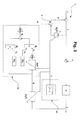
Fig. 3 shows a first embodiment of a system according to the present invention; -
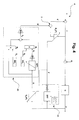
Fig. 4 shows a second embodiment of system according to the present invention. - The description of the present invention will refer to embodiments as implemented for controlling the elevation and direction of the gun barrel of a military tank. This should, however, not be considered as limiting the present invention to these embodiments, but instead be viewed as illustrative examples.
-
Fig. 1 schematically illustrates an example of afeedback control system 1, represented by the dotted lines, for controlling the output signal y of a real system G. In thefeedback control system 1, the output signal y from the real system G is fed back to and subtracted from a reference signal r. The resulting signal z is used as an input into a controller A outputting the input signal u to the real system G. Also illustrated inFig. 1 , is how a disturbance d is introduced and added to the input signal u before being inputted into the real system G which in turn outputs the signal y. Because of reasons mentioned in the background above, a disturbance can often be present in the input signal to the real system G, for example, as depicted in thefeedback control system 1 inFig. 1 , and if the frequency or frequencies of the disturbance is below the bandwidth of thefeedback control system 1, the feedback control system can be designed to eliminate or alleviate the effects of this disturbance on the output signal y. However, if the frequency range in which the disturbance is located is above the bandwidth of thefeedback control system 1, the disturbance will remain and ultimately affect the output signal y, since it can not be attended to by thefeedback control system 1. The disturbance d is such an out-of-band disturbance, that is, the frequency range of the disturbance is located outside of the bandwidth of thefeedback control system 1, and is therefore depicted in thefeedback control system 1 as introduced before the real system G, and thereby also introduced in thefeedback control system 1. - An example of the
feedback control system 1 illustrated inFig.1 is the servo system for controlling the elevation and direction of the gun barrel on a military tank. The out-of-band disturbance signal d is in this case the previously mentioned frequency variant, narrow band disturbance caused by the interconnected links of the driving bands. - The
feedback control system 1 could of course be any form of closed loop control system and is simply depicted for the benefit of providing a skilled person with a better understanding of the present invention. As an example, the reference signal r could be an output signal from a control unit, joystick etc., operated by a tank operator e.g. for aiming the gun barrel at a target, and the controller A could be could be a PID-controller designed and adapted for controlling thefeedback control system 1. -
Fig. 2 schematically illustrates an inner feedback loop for eliminating an out-of band disturbance according to prior art.
An out-of-band disturbance signal d is introduced and added to a signal v, which comprises an input signal u and an estimate d' of the disturbance signal d.
To obtain the estimated signal d', the output signal y is fed back into an estimated model G'-1 of the inverse of the real system G. From the output of the estimated model G'-1, the signal v is subtracted and the resulting signal sent to a frequency variant filter F(f). From the filter F(f), an estimated signal d' of the disturbance d is outputted. - In order to arrive at the model G'-1, a frequency analysis, e.g. a Bode-diagram, of the real system G is performed. By adapting a linear system to the measured data from the frequency analysis and inverting the linear system, an estimated model of the inverse system G'-1 is created.
The estimated model G'-1 is also arranged to be causal according to thefollowing equation 1 in the Laplace domain:
- The transfer function of the inner feedback loop in
Fig. 2 , from the input signal u and the disturbance signal d to the output signal y, is shown in equation 2:
- However, a problem in the prior art is that it is very difficult to find a linear system which can, after being adapted to the measured data of the real system G and inverted and made causal, accurately correspond to the behaviour of the real system G across the whole desired frequency range.
- Another problem in the prior art is when the real system G is a system with a non-minimum phase behaviour. This implies that the linear system adapted to the measured data of the real system G has a transfer function in the Laplace domain which has zeros in the right half plane of the s-plane. Consequently, the inverse of the linear system adapted to the measured data of the real system G'-1 has a transfer function in the Laplace domain which has poles in the right half plane, which means that is G'-1 is unstable.
- These problems render the prior art solutions difficult to design in view of all system design parameters, i.e. performance, stability, robustness and accuracy etc., over the entire frequency spectrum of interest and are therefore not able to eliminate out-of-band disturbances in a satisfying way.
-
Fig. 3 illustrates a first embodiment of the present invention comprising an inner feedback loop for eliminating an out-of-band disturbance.
As inFig. 1 , an out-of-band disturbance signal d is added to a signal v, which comprises an input signal u and an estimate d' of the disturbance signal d. To get the estimated signal d', the output signal y is first fed back into to an adjustable, narrow band pass filter B1 which is arranged to output a signal S. - For the adjustable, narrow band pass filter B1, the main frequency f0 of the disturbance signal d can be approximately estimated by the frequency estimation means 3A according to the following equation 3:

- The known, continuous function F(x) of the measurable system variable x, for example the speed of the driving bands, can be achieved empirically by testing and experimenting on the real system G. Therefore, the narrow band pass filter B1, can be designed as time-variant band pass filter B1(f'), wherein the band pass frequency is set to be the estimated main frequency f', which means that the variation of the time-variant band pass filter B1(f') is adapted to the variation of the main frequency f0 of the frequency variant, narrow band disturbance.
- Then, in the inner feedback loop, the signal S can be written according to either one of the following equations 4-5:


wherein theequation 5 the real system G has shifted the phase of the input signal v + d at the frequency f' with the angle ϕG and multiplied it with again 
- The signal S is used as input into a low-pass filter A(f) and also into a multiplier M2. The low-pass filter A(f') is designed to add a phase shift of 90° to its input signal S by also utilizing the same known, continuous function F(x) as the adjustable, narrow band pass filter B1(f'). Unfortunately, it also adds a gain of

It should be understood that the main purpose of the low-pass filter A(f') is to add a phase shift of 90° to the input signal S and for which there are several different filter designs applicable. In this case, the consequential added gain of the low-pass filter A(f') is just a bi-product of the filter and could be removed in any suitable way. The signal S1 can therefore be written according to the following equation 6:
- The signals S1 and S, wherein S is the output signal from the adjustable, narrow band pass filter B1(f'), are then multiplied with the signals S2 and S3 respectively in the multipliers M1 and M2. The signals S2 and S3 are created in signal generators SG2 and SG3, respectively, and according to the following equations 7 and 8:


where the angle ϕG is the phase shift of the real system G at the frequency f' which is obtained from a table of system parameters T that has been achieved by a frequency analysis of the real system G. - The outputs from the multipliers M1 and M2 are then added to form the signal S0. Because of the trigonometric relationships between the output signals from the multipliers M1 and M2, the signal S0 becomes identical to the output from the filter B1(f') although including a phase shift of the angle ϕG. The trigonometric relationships in the signal S0 can be written according to the following equations 9-11:


- Therefore the summed output signal S0 can be written according to the following equation 12:

- Then the summed output signal S0 is, by using a gain multiplier KG, multiplied with a gain KG, also obtained from the previously mentioned table of system parameters T. This results in that the attenuation, or damping, and phase loss which the real system G has enforced on the control signal v and the disturbance signal d at the frequency f' resulting in the output signal y have been compensated for without having to invert an adapted linear system model of the real system G.
- The signal v, for which most of the frequencies outside the main frequency f0 of the frequency variant, narrow band disturbance d has been filtered out by being passed through an adjustable, narrow band pass filter B2(f'), identical to the adjustable, narrow band pass filter B1(f'), is then subtracted from the signal S' leaving the resulting signal d' comprising an estimate of the disturbance signal d. As can be seen from
Fig. 3 , this results in that the estimated disturbance signal d' is subtracted from the input signal u and, since d' approximates d, thus eliminates or at least suppresses the effects of added the disturbance signal d on the output signal y from the real system G. - This means that the present invention can eliminate or suppress the effects of a disturbance signal introduced to the real system G, even when the real system G is a non-minimum phase system, without resulting in an unstable control loop. It also means that the present invention can eliminate or at least suppress out-of-band, frequency variant noise in a feedback control system, for example, the
feedback control system 1 inFig. 1 . -
Fig. 4 illustrates a second embodiment according to the present invention. The inner feedback loop depicted inFig.4 is identical to the inner feedback loop inFig. 3 , except that this second embodiment also comprises frequency estimation means 4A instead of 3A, which includes calculation means DFT and extraction means max, for improving the estimation of the main frequency of the out-of-band, frequency variant disturbance d. - So, in addition to the output signal y being fed back into to the adjustable, narrow band pass filter B1(f*), the output signal y is also fed back into the calculation means DFT. The calculation means DFT uses the discrete Fourier transform to calculate the frequency spectrum of the output signal y on a predetermined interval I, defined according to the equation 13:

where f0 is estimated by the predetermined known continuous function F(x), according toequation 3 described in reference toFig. 2 , and a is a suitable parameter depending on, and is preferably calibrated for, each specific implementation of the present invention. - The extraction means max then searches across the frequencies of the frequency spectrum of the interval I for a peak energy value. Once a maximum energy value for the frequency spectrum has been found, the frequency f* where this maximum energy value occurs is extracted and set as the main frequency of f0 of the disturbance signal d. The frequency value f* is then used for adjusting the band pass frequencies of the filters B1(f*) and B2(f*), and also for adjusting the filter A(f*). Also, it should be noted the calculation means DFT and the extraction means max can easily be implemented integrally and are separated herein only for the sake of clarity.
- The calculation means DFT enables the inner feedback loop to automatically and more accurately estimate the main frequency f0 of the disturbance signal d.
Claims (15)
- A system for suppressing frequency variant disturbances in a feedback control system (1), wherein said system is a inner feedback loop in the feedback control system (1) comprising a real system (G) connected to a first filtering means (B1(f'); B1(f*)), which is connected to a frequency estimation means (3A; 4A) and a system modelling means (3B; 4B), wherein said system modelling means (3B; 4B) is connected to a second filtering means (B2(f'); B2(f*)) via a subtraction means (5),
characterized in that
said frequency estimation means (3A; 4A) comprises means for estimating the main frequency (f ; f*) of a disturbance (d);
said first filtering means (B1(f'); B1(f*)) is arranged to remove the frequency content in a first feedback signal (y) around said estimated main frequency (f'; f*);
said second filtering means (B2(f'); B2(f*))is arranged to remove the frequency content in a second feedback signal (v) around said estimated main frequency (f'; f*);
said system modelling means (3B; 4B) comprises means arranged to use an second input signal (S) from said first filtering means (B1(f'); B1(f*)) and said estimated main frequency (f ; f*) for modelling and compensating for the damping and the phase loss of said real system (G); and
said subtraction means (5) is arranged to subtract an first output signal from said second filtering means (B2(f'); B2(f*)) from an second output signal (S') from said system modelling means (3B; 4B) to get an estimated disturbance signal (d') added to an first input signal (u) of said inner feedback loop. - A system according to claim 1, wherein said first and second filtering means (B1(f'); B1(f*); B2(f'); B2(f*)) are frequency variant, narrow band pass filters arranged to be adjusted in accordance with said estimated main frequency (f'; f*).
- A system according to any of the claims 1 to 2, wherein said system modelling means (3B; 4B) comprisesa third filtering means (A(f'); A(f*)) arranged to add a 90° phase shift to a second input signal (S) at said estimated main frequency (f';f*);a first gain multiplier (KA) arranged to remove the added gain of said third filtering means (A(f'); A(f*));a first and a second signal generator (SG2, SG3) arranged to generate a third and fourth output signal (S2, S3) respectively;a first and a second multiplier (M1, M2) arranged to multiply said third output signal (S2) of said first signal generator (SG2) with a fifth output signal (S1) of said first gain multiplier (KA) and said fourth output signal (S3) of said second signal generator (SG3) with said second input signal (S) respectively; a summing node arranged to sum a sixth and seventh output signal of said first and second multiplier (M1, M2) and a second gain multiplier (KG) arranged to remove the added gain of said real system (G).
- A system according to claim 3, wherein said third filtering means (A(f'); A(f*)) is a frequency variant, low pass filter arranged to be adjusted in accordance with said estimated main frequency (f'; f*).
- A system according to claim 3 or 4, wherein said first and second signal generator (SG2, SG3) are arranged to generate said third and fourth output signals (S2, S3) in dependence of a table (T) and also said second gain multiplier (KG) is arranged to add a gain in dependence of said table (T), wherein said table (T) comprises the phase shift and added gain of the real system (G) at different frequencies.
- A system according to any of the claims 1 to 5, wherein said frequency estimation means (3A; 4A) comprises calculation means arranged to use a predetermined, continuous function (F(x)) of a measurable system variable (x) of said real system (G).
- A system according to any of the claims 1 to 5, wherein said frequency estimation means (3A; 4A) comprisescalculation means (DFT) arranged to use the discrete Fourier transform to calculate the frequency spectrum of said feedback signal (y) on a predetermined interval (I) andextraction means (max) arranged to extract the frequency which has the maximum energy peak value in said frequency spectrum and set said extracted frequency as the estimated main frequency (f'; f*) of said disturbance (d).
- A system according to claim 7, wherein said predetermined interval (I) is determined by using said predetermined, continuous function (F(x)) of said measurable system variable (x) of said real system (G).
- A system according to any of the claims 6 or 8, wherein said measurable system variable (x) of said real system (G) is the speed of the driving bands of a military tank.
- A method for suppressing frequency variant disturbances (d) in a system for suppressing frequency variant disturbances in a feedback control system (1), wherein said system is a inner feedback loop in the feedback control system (1) comprising a real system (G) connected to a first filtering means (B1(f'); B1(f*)), which is connected to a frequency estimation means (3A; 4A) and a system modelling means (3B; 4B), wherein said system modelling means (3B; 4B) is connected to a second filtering means (B2(f'); B2(f*)) via a subtraction means (5),
characterized in
comprising the steps of:- estimating the main frequency (f ; f*) of a disturbance (d);- filtering out the frequency content in a first feedback signal (y) and a second feedback signal (v) around said estimated main frequency (f; f*);- modelling and compensating for the damping and the phase loss of said real system (G) using said estimated main frequency (f ; f*) and a second input signal (S);- producing a damping and phase compensated second output signal (S');- producing an estimated disturbance signal (d') by subtracting a first output signal from said second filtering means (B2(f'); B2(f*)) from said second output signal (S'); and- adding said estimated disturbance signal (d') to a first input signal (u) of said inner feedback loop. - A method according to claim 10, wherein the step of modelling and compensating for the damping and the phase loss of said real system (G) using said estimated main frequency (f ; f*) and the filtered first feedback signal (y) further comprises the steps of:- adding a 90° phase shift to an second input signal (S) at said estimated main frequency (f';f*) by using a third filtering means (A(f'); A(f*));- removing the added gain of said third filtering means (A(f'); A(f*)) by using a first gain multiplier (KA);- generating third and fourth output signal (S2, S3) from a first and a second signal generator (SG2, SG3), respectively;- multiplying said third output signal (S2) of said first signal generator (SG2) with a fifth output signal (S1) of said first gain multiplier (KA) and said fourth output signal (S3) of said second signal generator (SG3) with said second input signal (S) by using a first and a second multiplier (M1, M2), respectively;- summing a sixth and seventh output signal of said first and second multiplier (M1, M2), respectively, by using a summing node;- removing the added gain of said real system (G) by using a second gain multiplier (KG).
- A method according to claim 11, wherein the step of generating said third and fourth output signal (S2, S3) from a first and a second signal generator (SG2, SG3), respectively, and the step of removing the added gain of said real system (G) by using a second gain multiplier (KG) is performed in dependence of a table (T) comprising the phase shift and added gain of the real system (G) at different frequencies.
- A method according to any of the claims 10 to 12, wherein the step of estimating the main frequency (f; f*) of said disturbance (d) further comprises the step of:- using a predetermined, continuous function (F(x)) of a measurable system variable (x) of said real system (G).
- A method according to any of the claims 10 to 13, wherein the step of estimating the main frequency (f'; f*) of said disturbance (d) further comprises the steps of:- using the discrete Fourier transform to calculate the frequency spectrum of said feedback signal (y) on a predetermined interval (I);- extracting the frequency which has the maximum energy peak value in said frequency spectrum; and- setting said extracted frequency as the estimated main frequency (f; f*) of said disturbance (d).
- A method according to claim 14, wherein the step of estimating the main frequency (f; f*) of said disturbance (d) further comprises the step of:- using said predetermined, continuous function (F(x)) of said measurable system variable (x) of said real system (G) to determine said predetermined interval (I).
Priority Applications (5)
| Application Number | Priority Date | Filing Date | Title |
|---|---|---|---|
| DK07100599.5T DK1947533T3 (en) | 2007-01-16 | 2007-01-16 | System and method for suppressing interference in a feed-back control system |
| EP07100599A EP1947533B1 (en) | 2007-01-16 | 2007-01-16 | A system and a method for suppressing disturbances in a feedback control system |
| ES07100599T ES2342331T3 (en) | 2007-01-16 | 2007-01-16 | SYSTEM AND PROCEDURE TO DELETE DISTURBANCES IN A FEEDBACK CONTROL SYSTEM. |
| DE602007006145T DE602007006145D1 (en) | 2007-01-16 | 2007-01-16 | A system and method for suppressing disturbances in a feedback control system |
| AT07100599T ATE466318T1 (en) | 2007-01-16 | 2007-01-16 | SYSTEM AND METHOD FOR SUPPRESSING DISTURBANCES IN A FEEDBACK CONTROL SYSTEM |
Applications Claiming Priority (1)
| Application Number | Priority Date | Filing Date | Title |
|---|---|---|---|
| EP07100599A EP1947533B1 (en) | 2007-01-16 | 2007-01-16 | A system and a method for suppressing disturbances in a feedback control system |
Publications (2)
| Publication Number | Publication Date |
|---|---|
| EP1947533A1 true EP1947533A1 (en) | 2008-07-23 |
| EP1947533B1 EP1947533B1 (en) | 2010-04-28 |
Family
ID=38110636
Family Applications (1)
| Application Number | Title | Priority Date | Filing Date |
|---|---|---|---|
| EP07100599A Not-in-force EP1947533B1 (en) | 2007-01-16 | 2007-01-16 | A system and a method for suppressing disturbances in a feedback control system |
Country Status (5)
| Country | Link |
|---|---|
| EP (1) | EP1947533B1 (en) |
| AT (1) | ATE466318T1 (en) |
| DE (1) | DE602007006145D1 (en) |
| DK (1) | DK1947533T3 (en) |
| ES (1) | ES2342331T3 (en) |
Cited By (1)
| Publication number | Priority date | Publication date | Assignee | Title |
|---|---|---|---|---|
| CN109946979A (en) * | 2019-04-25 | 2019-06-28 | 广东省智能机器人研究院 | A kind of self-adapting regulation method of servo-system sensitivity function |
-
2007
- 2007-01-16 EP EP07100599A patent/EP1947533B1/en not_active Not-in-force
- 2007-01-16 ES ES07100599T patent/ES2342331T3/en active Active
- 2007-01-16 AT AT07100599T patent/ATE466318T1/en not_active IP Right Cessation
- 2007-01-16 DK DK07100599.5T patent/DK1947533T3/en active
- 2007-01-16 DE DE602007006145T patent/DE602007006145D1/en active Active
Non-Patent Citations (8)
| Title |
|---|
| BODSON M ET AL., PROCEEDINGS OF THE SPIE, vol. 2715, 1996, pages 64 - 75 |
| BODSON M ET AL: "Rejection of disturbances with a large sinusoidal component of unknown frequency", PROCEEDINGS OF THE SPIE, SPIE, BELLINGHAM, VA, US, vol. 2715, 1996, pages 64 - 75, XP002402299, ISSN: 0277-786X * |
| HILLIS A J ET AL.: "A comparison of two adaptive algorithms for the control of active engine mounts", JOURNAL OF SOUND AND VIBRATION, vol. 286, no. 1-2, 2005, pages 37 - 54, XP004939198, DOI: doi:10.1016/j.jsv.2004.09.023 |
| HILLIS A J ET AL: "A comparison of two adaptive algorithms for the control of active engine mounts", JOURNAL OF SOUND & VIBRATION, LONDON, GB, vol. 286, no. 1-2, 23 August 2005 (2005-08-23), pages 37 - 54, XP004939198, ISSN: 0022-460X * |
| JIENG-JANG LIU ET AL.: "CONTROL ENGINEERING PRACTICE", vol. 12, 2004, PERGAMON PRESS, article "Frequency adaptive control technique for rejecting periodic run-out", pages: 31 - 40 |
| JIENG-JANG LIU ET AL: "Frequency adaptive control technique for rejecting periodic runout", CONTROL ENGINEERING PRACTICE, PERGAMON PRESS, OXFORD, GB, vol. 12, no. 1, January 2004 (2004-01-01), pages 31 - 40, XP002402300, ISSN: 0967-0661 * |
| RASHID AMIR ET AL.: "INTERNATIONAL JOURNAL OF MACHINE TOOL DESIGN AND RESEARCH", vol. 46, 2006, PERGAMON PRESS, pages: 1626 - 1636 |
| RASHID ET AL: "Active vibration control in palletised workholding system for milling", INTERNATIONAL JOURNAL OF MACHINE TOOL DESIGN AND RESEARCH, PERGAMON PRESS, OXFORD, GB, vol. 46, no. 12-13, October 2006 (2006-10-01), pages 1626 - 1636, XP005585850, ISSN: 0890-6955 * |
Cited By (2)
| Publication number | Priority date | Publication date | Assignee | Title |
|---|---|---|---|---|
| CN109946979A (en) * | 2019-04-25 | 2019-06-28 | 广东省智能机器人研究院 | A kind of self-adapting regulation method of servo-system sensitivity function |
| CN109946979B (en) * | 2019-04-25 | 2022-03-22 | 广东省智能机器人研究院 | Self-adaptive adjusting method for sensitivity function of servo system |
Also Published As
| Publication number | Publication date |
|---|---|
| DE602007006145D1 (en) | 2010-06-10 |
| ATE466318T1 (en) | 2010-05-15 |
| DK1947533T3 (en) | 2010-07-19 |
| ES2342331T3 (en) | 2010-07-05 |
| EP1947533B1 (en) | 2010-04-28 |
Similar Documents
| Publication | Publication Date | Title |
|---|---|---|
| WO2018003201A1 (en) | Motor drive system | |
| KR102389093B1 (en) | Steering control apparatus and steering control method | |
| US9197262B2 (en) | Low-power and low-cost adaptive self-linearization system with fast convergence | |
| CN106796783A (en) | Active type noise reduction apparatus | |
| US6212540B1 (en) | Filter circuit | |
| CN107291998B (en) | Novel low-pass filter design method based on sliding mode idea | |
| JP6197923B1 (en) | Control system | |
| EP1947533A1 (en) | A system and a method for suppressing disturbances in a feedback control system | |
| JP4788656B2 (en) | Power test system | |
| JP6708925B2 (en) | Control system | |
| Buchholz et al. | Online-identification of the machine parameters of an induction motor drive | |
| CN109828469B (en) | Phase-optimized extended state observer and anti-interference control system | |
| CN107425826B (en) | Adaptive filtering method, adaptive filter, and storage medium | |
| CN109960843B (en) | Doppler frequency shift numerical simulation method based on orthogonal principle | |
| CN112081585A (en) | Autonomous focusing circuit of array lateral logging instrument and control method | |
| KR100512552B1 (en) | Apparatus and method of detecting a movement by a radar, using finite interval moving slide window impulse filter | |
| RU202917U1 (en) | Device for nonlinear correction in electromechanical systems | |
| CN116324632B (en) | Vehicle system vibration suppression control apparatus and vibration suppression control method | |
| CN115357063B (en) | Servo system vibration suppression method based on strong tracking of reference track | |
| CN112649874A (en) | Sticky sound reverse time migration method and system based on low-rank decomposition | |
| CN109633623B (en) | Radar speed tracking loop design method | |
| CN106250671A (en) | A kind of cube phase place modulated parameter estimating method of bilinearity coherent | |
| EP2677375B1 (en) | Apparatus and method for controlling input signal | |
| JP4471932B2 (en) | Control target parameter identification method | |
| Wang et al. | Research and Application of PID Controller with Feedforward Filtering Function |
Legal Events
| Date | Code | Title | Description |
|---|---|---|---|
| PUAI | Public reference made under article 153(3) epc to a published international application that has entered the european phase |
Free format text: ORIGINAL CODE: 0009012 |
|
| AK | Designated contracting states |
Kind code of ref document: A1 Designated state(s): AT BE BG CH CY CZ DE DK EE ES FI FR GB GR HU IE IS IT LI LT LU LV MC NL PL PT RO SE SI SK TR |
|
| AX | Request for extension of the european patent |
Extension state: AL BA HR MK RS |
|
| 17P | Request for examination filed |
Effective date: 20090122 |
|
| 17Q | First examination report despatched |
Effective date: 20090227 |
|
| AKX | Designation fees paid |
Designated state(s): AT BE BG CH CY CZ DE DK EE ES FI FR GB GR HU IE IS IT LI LT LU LV MC NL PL PT RO SE SI SK TR |
|
| GRAP | Despatch of communication of intention to grant a patent |
Free format text: ORIGINAL CODE: EPIDOSNIGR1 |
|
| GRAS | Grant fee paid |
Free format text: ORIGINAL CODE: EPIDOSNIGR3 |
|
| GRAA | (expected) grant |
Free format text: ORIGINAL CODE: 0009210 |
|
| AK | Designated contracting states |
Kind code of ref document: B1 Designated state(s): AT BE BG CH CY CZ DE DK EE ES FI FR GB GR HU IE IS IT LI LT LU LV MC NL PL PT RO SE SI SK TR |
|
| REG | Reference to a national code |
Ref country code: GB Ref legal event code: FG4D |
|
| REG | Reference to a national code |
Ref country code: CH Ref legal event code: EP |
|
| REG | Reference to a national code |
Ref country code: IE Ref legal event code: FG4D |
|
| REF | Corresponds to: |
Ref document number: 602007006145 Country of ref document: DE Date of ref document: 20100610 Kind code of ref document: P |
|
| REG | Reference to a national code |
Ref country code: SE Ref legal event code: TRGR |
|
| REG | Reference to a national code |
Ref country code: ES Ref legal event code: FG2A Ref document number: 2342331 Country of ref document: ES Kind code of ref document: T3 |
|
| REG | Reference to a national code |
Ref country code: CH Ref legal event code: NV Representative=s name: ARNOLD & SIEDSMA AG |
|
| REG | Reference to a national code |
Ref country code: DK Ref legal event code: T3 |
|
| REG | Reference to a national code |
Ref country code: NL Ref legal event code: T3 |
|
| LTIE | Lt: invalidation of european patent or patent extension |
Effective date: 20100428 |
|
| PG25 | Lapsed in a contracting state [announced via postgrant information from national office to epo] |
Ref country code: LT Free format text: LAPSE BECAUSE OF FAILURE TO SUBMIT A TRANSLATION OF THE DESCRIPTION OR TO PAY THE FEE WITHIN THE PRESCRIBED TIME-LIMIT Effective date: 20100428 |
|
| PG25 | Lapsed in a contracting state [announced via postgrant information from national office to epo] |
Ref country code: LV Free format text: LAPSE BECAUSE OF FAILURE TO SUBMIT A TRANSLATION OF THE DESCRIPTION OR TO PAY THE FEE WITHIN THE PRESCRIBED TIME-LIMIT Effective date: 20100428 Ref country code: IS Free format text: LAPSE BECAUSE OF FAILURE TO SUBMIT A TRANSLATION OF THE DESCRIPTION OR TO PAY THE FEE WITHIN THE PRESCRIBED TIME-LIMIT Effective date: 20100828 Ref country code: SI Free format text: LAPSE BECAUSE OF FAILURE TO SUBMIT A TRANSLATION OF THE DESCRIPTION OR TO PAY THE FEE WITHIN THE PRESCRIBED TIME-LIMIT Effective date: 20100428 Ref country code: AT Free format text: LAPSE BECAUSE OF FAILURE TO SUBMIT A TRANSLATION OF THE DESCRIPTION OR TO PAY THE FEE WITHIN THE PRESCRIBED TIME-LIMIT Effective date: 20100428 |
|
| PG25 | Lapsed in a contracting state [announced via postgrant information from national office to epo] |
Ref country code: CY Free format text: LAPSE BECAUSE OF FAILURE TO SUBMIT A TRANSLATION OF THE DESCRIPTION OR TO PAY THE FEE WITHIN THE PRESCRIBED TIME-LIMIT Effective date: 20100526 Ref country code: PL Free format text: LAPSE BECAUSE OF FAILURE TO SUBMIT A TRANSLATION OF THE DESCRIPTION OR TO PAY THE FEE WITHIN THE PRESCRIBED TIME-LIMIT Effective date: 20100428 |
|
| PG25 | Lapsed in a contracting state [announced via postgrant information from national office to epo] |
Ref country code: PT Free format text: LAPSE BECAUSE OF FAILURE TO SUBMIT A TRANSLATION OF THE DESCRIPTION OR TO PAY THE FEE WITHIN THE PRESCRIBED TIME-LIMIT Effective date: 20100830 Ref country code: GR Free format text: LAPSE BECAUSE OF FAILURE TO SUBMIT A TRANSLATION OF THE DESCRIPTION OR TO PAY THE FEE WITHIN THE PRESCRIBED TIME-LIMIT Effective date: 20100729 Ref country code: EE Free format text: LAPSE BECAUSE OF FAILURE TO SUBMIT A TRANSLATION OF THE DESCRIPTION OR TO PAY THE FEE WITHIN THE PRESCRIBED TIME-LIMIT Effective date: 20100428 |
|
| PG25 | Lapsed in a contracting state [announced via postgrant information from national office to epo] |
Ref country code: SK Free format text: LAPSE BECAUSE OF FAILURE TO SUBMIT A TRANSLATION OF THE DESCRIPTION OR TO PAY THE FEE WITHIN THE PRESCRIBED TIME-LIMIT Effective date: 20100428 Ref country code: BE Free format text: LAPSE BECAUSE OF FAILURE TO SUBMIT A TRANSLATION OF THE DESCRIPTION OR TO PAY THE FEE WITHIN THE PRESCRIBED TIME-LIMIT Effective date: 20100428 Ref country code: RO Free format text: LAPSE BECAUSE OF FAILURE TO SUBMIT A TRANSLATION OF THE DESCRIPTION OR TO PAY THE FEE WITHIN THE PRESCRIBED TIME-LIMIT Effective date: 20100428 Ref country code: CZ Free format text: LAPSE BECAUSE OF FAILURE TO SUBMIT A TRANSLATION OF THE DESCRIPTION OR TO PAY THE FEE WITHIN THE PRESCRIBED TIME-LIMIT Effective date: 20100428 |
|
| PLBE | No opposition filed within time limit |
Free format text: ORIGINAL CODE: 0009261 |
|
| STAA | Information on the status of an ep patent application or granted ep patent |
Free format text: STATUS: NO OPPOSITION FILED WITHIN TIME LIMIT |
|
| PG25 | Lapsed in a contracting state [announced via postgrant information from national office to epo] |
Ref country code: IT Free format text: LAPSE BECAUSE OF FAILURE TO SUBMIT A TRANSLATION OF THE DESCRIPTION OR TO PAY THE FEE WITHIN THE PRESCRIBED TIME-LIMIT Effective date: 20100428 |
|
| 26N | No opposition filed |
Effective date: 20110131 |
|
| PG25 | Lapsed in a contracting state [announced via postgrant information from national office to epo] |
Ref country code: MC Free format text: LAPSE BECAUSE OF NON-PAYMENT OF DUE FEES Effective date: 20110131 |
|
| REG | Reference to a national code |
Ref country code: FR Ref legal event code: ST Effective date: 20110930 |
|
| REG | Reference to a national code |
Ref country code: IE Ref legal event code: MM4A |
|
| PG25 | Lapsed in a contracting state [announced via postgrant information from national office to epo] |
Ref country code: FR Free format text: LAPSE BECAUSE OF NON-PAYMENT OF DUE FEES Effective date: 20110131 |
|
| REG | Reference to a national code |
Ref country code: DE Ref legal event code: R119 Ref document number: 602007006145 Country of ref document: DE Effective date: 20110802 |
|
| PG25 | Lapsed in a contracting state [announced via postgrant information from national office to epo] |
Ref country code: IE Free format text: LAPSE BECAUSE OF NON-PAYMENT OF DUE FEES Effective date: 20110116 |
|
| PG25 | Lapsed in a contracting state [announced via postgrant information from national office to epo] |
Ref country code: LU Free format text: LAPSE BECAUSE OF NON-PAYMENT OF DUE FEES Effective date: 20110116 |
|
| PG25 | Lapsed in a contracting state [announced via postgrant information from national office to epo] |
Ref country code: DE Free format text: LAPSE BECAUSE OF NON-PAYMENT OF DUE FEES Effective date: 20110802 |
|
| PG25 | Lapsed in a contracting state [announced via postgrant information from national office to epo] |
Ref country code: BG Free format text: LAPSE BECAUSE OF FAILURE TO SUBMIT A TRANSLATION OF THE DESCRIPTION OR TO PAY THE FEE WITHIN THE PRESCRIBED TIME-LIMIT Effective date: 20100728 Ref country code: TR Free format text: LAPSE BECAUSE OF FAILURE TO SUBMIT A TRANSLATION OF THE DESCRIPTION OR TO PAY THE FEE WITHIN THE PRESCRIBED TIME-LIMIT Effective date: 20100428 |
|
| PG25 | Lapsed in a contracting state [announced via postgrant information from national office to epo] |
Ref country code: HU Free format text: LAPSE BECAUSE OF FAILURE TO SUBMIT A TRANSLATION OF THE DESCRIPTION OR TO PAY THE FEE WITHIN THE PRESCRIBED TIME-LIMIT Effective date: 20100428 |
|
| PGFP | Annual fee paid to national office [announced via postgrant information from national office to epo] |
Ref country code: SE Payment date: 20211206 Year of fee payment: 16 Ref country code: DK Payment date: 20211206 Year of fee payment: 16 Ref country code: FI Payment date: 20211207 Year of fee payment: 16 Ref country code: GB Payment date: 20211206 Year of fee payment: 16 |
|
| PGFP | Annual fee paid to national office [announced via postgrant information from national office to epo] |
Ref country code: CH Payment date: 20211206 Year of fee payment: 16 |
|
| PGFP | Annual fee paid to national office [announced via postgrant information from national office to epo] |
Ref country code: NL Payment date: 20211206 Year of fee payment: 16 |
|
| PGFP | Annual fee paid to national office [announced via postgrant information from national office to epo] |
Ref country code: ES Payment date: 20220304 Year of fee payment: 16 |
|
| REG | Reference to a national code |
Ref country code: DK Ref legal event code: EBP Effective date: 20230131 |
|
| REG | Reference to a national code |
Ref country code: SE Ref legal event code: EUG |
|
| REG | Reference to a national code |
Ref country code: CH Ref legal event code: PL |
|
| REG | Reference to a national code |
Ref country code: NL Ref legal event code: MM Effective date: 20230201 |
|
| GBPC | Gb: european patent ceased through non-payment of renewal fee |
Effective date: 20230116 |
|
| PG25 | Lapsed in a contracting state [announced via postgrant information from national office to epo] |
Ref country code: SE Free format text: LAPSE BECAUSE OF NON-PAYMENT OF DUE FEES Effective date: 20230117 Ref country code: NL Free format text: LAPSE BECAUSE OF NON-PAYMENT OF DUE FEES Effective date: 20230201 Ref country code: LI Free format text: LAPSE BECAUSE OF NON-PAYMENT OF DUE FEES Effective date: 20230131 Ref country code: GB Free format text: LAPSE BECAUSE OF NON-PAYMENT OF DUE FEES Effective date: 20230116 Ref country code: FI Free format text: LAPSE BECAUSE OF NON-PAYMENT OF DUE FEES Effective date: 20230116 Ref country code: CH Free format text: LAPSE BECAUSE OF NON-PAYMENT OF DUE FEES Effective date: 20230131 |
|
| PG25 | Lapsed in a contracting state [announced via postgrant information from national office to epo] |
Ref country code: DK Free format text: LAPSE BECAUSE OF NON-PAYMENT OF DUE FEES Effective date: 20230131 |
|
| REG | Reference to a national code |
Ref country code: ES Ref legal event code: FD2A Effective date: 20240327 |
|
| PG25 | Lapsed in a contracting state [announced via postgrant information from national office to epo] |
Ref country code: ES Free format text: LAPSE BECAUSE OF NON-PAYMENT OF DUE FEES Effective date: 20230117 |
|
| PG25 | Lapsed in a contracting state [announced via postgrant information from national office to epo] |
Ref country code: ES Free format text: LAPSE BECAUSE OF NON-PAYMENT OF DUE FEES Effective date: 20230117 |