EP1947336A1 - Reciprocating compressor - Google Patents
Reciprocating compressor Download PDFInfo
- Publication number
- EP1947336A1 EP1947336A1 EP06781468A EP06781468A EP1947336A1 EP 1947336 A1 EP1947336 A1 EP 1947336A1 EP 06781468 A EP06781468 A EP 06781468A EP 06781468 A EP06781468 A EP 06781468A EP 1947336 A1 EP1947336 A1 EP 1947336A1
- Authority
- EP
- European Patent Office
- Prior art keywords
- discharge
- valve plate
- discharge chamber
- suction
- holes
- Prior art date
- Legal status (The legal status is an assumption and is not a legal conclusion. Google has not performed a legal analysis and makes no representation as to the accuracy of the status listed.)
- Withdrawn
Links
Images


Classifications
-
- F—MECHANICAL ENGINEERING; LIGHTING; HEATING; WEAPONS; BLASTING
- F04—POSITIVE - DISPLACEMENT MACHINES FOR LIQUIDS; PUMPS FOR LIQUIDS OR ELASTIC FLUIDS
- F04B—POSITIVE-DISPLACEMENT MACHINES FOR LIQUIDS; PUMPS
- F04B39/00—Component parts, details, or accessories, of pumps or pumping systems specially adapted for elastic fluids, not otherwise provided for in, or of interest apart from, groups F04B25/00 - F04B37/00
- F04B39/0027—Pulsation and noise damping means
- F04B39/0055—Pulsation and noise damping means with a special shape of fluid passage, e.g. bends, throttles, diameter changes, pipes
-
- F—MECHANICAL ENGINEERING; LIGHTING; HEATING; WEAPONS; BLASTING
- F04—POSITIVE - DISPLACEMENT MACHINES FOR LIQUIDS; PUMPS FOR LIQUIDS OR ELASTIC FLUIDS
- F04B—POSITIVE-DISPLACEMENT MACHINES FOR LIQUIDS; PUMPS
- F04B27/00—Multi-cylinder pumps specially adapted for elastic fluids and characterised by number or arrangement of cylinders
- F04B27/08—Multi-cylinder pumps specially adapted for elastic fluids and characterised by number or arrangement of cylinders having cylinders coaxial with, or parallel or inclined to, main shaft axis
- F04B27/0804—Multi-cylinder pumps specially adapted for elastic fluids and characterised by number or arrangement of cylinders having cylinders coaxial with, or parallel or inclined to, main shaft axis having rotary cylinder block
- F04B27/0821—Multi-cylinder pumps specially adapted for elastic fluids and characterised by number or arrangement of cylinders having cylinders coaxial with, or parallel or inclined to, main shaft axis having rotary cylinder block component parts, details, e.g. valves, sealings, lubrication
- F04B27/0834—Multi-cylinder pumps specially adapted for elastic fluids and characterised by number or arrangement of cylinders having cylinders coaxial with, or parallel or inclined to, main shaft axis having rotary cylinder block component parts, details, e.g. valves, sealings, lubrication cylinder barrel
-
- F—MECHANICAL ENGINEERING; LIGHTING; HEATING; WEAPONS; BLASTING
- F04—POSITIVE - DISPLACEMENT MACHINES FOR LIQUIDS; PUMPS FOR LIQUIDS OR ELASTIC FLUIDS
- F04B—POSITIVE-DISPLACEMENT MACHINES FOR LIQUIDS; PUMPS
- F04B27/00—Multi-cylinder pumps specially adapted for elastic fluids and characterised by number or arrangement of cylinders
- F04B27/08—Multi-cylinder pumps specially adapted for elastic fluids and characterised by number or arrangement of cylinders having cylinders coaxial with, or parallel or inclined to, main shaft axis
- F04B27/10—Multi-cylinder pumps specially adapted for elastic fluids and characterised by number or arrangement of cylinders having cylinders coaxial with, or parallel or inclined to, main shaft axis having stationary cylinders
- F04B27/1036—Component parts, details, e.g. sealings, lubrication
- F04B27/1045—Cylinders
-
- F—MECHANICAL ENGINEERING; LIGHTING; HEATING; WEAPONS; BLASTING
- F04—POSITIVE - DISPLACEMENT MACHINES FOR LIQUIDS; PUMPS FOR LIQUIDS OR ELASTIC FLUIDS
- F04B—POSITIVE-DISPLACEMENT MACHINES FOR LIQUIDS; PUMPS
- F04B27/00—Multi-cylinder pumps specially adapted for elastic fluids and characterised by number or arrangement of cylinders
- F04B27/08—Multi-cylinder pumps specially adapted for elastic fluids and characterised by number or arrangement of cylinders having cylinders coaxial with, or parallel or inclined to, main shaft axis
- F04B27/10—Multi-cylinder pumps specially adapted for elastic fluids and characterised by number or arrangement of cylinders having cylinders coaxial with, or parallel or inclined to, main shaft axis having stationary cylinders
- F04B27/1036—Component parts, details, e.g. sealings, lubrication
- F04B27/1081—Casings, housings
-
- F—MECHANICAL ENGINEERING; LIGHTING; HEATING; WEAPONS; BLASTING
- F04—POSITIVE - DISPLACEMENT MACHINES FOR LIQUIDS; PUMPS FOR LIQUIDS OR ELASTIC FLUIDS
- F04B—POSITIVE-DISPLACEMENT MACHINES FOR LIQUIDS; PUMPS
- F04B39/00—Component parts, details, or accessories, of pumps or pumping systems specially adapted for elastic fluids, not otherwise provided for in, or of interest apart from, groups F04B25/00 - F04B37/00
- F04B39/0027—Pulsation and noise damping means
- F04B39/0055—Pulsation and noise damping means with a special shape of fluid passage, e.g. bends, throttles, diameter changes, pipes
- F04B39/0061—Pulsation and noise damping means with a special shape of fluid passage, e.g. bends, throttles, diameter changes, pipes using muffler volumes
-
- F—MECHANICAL ENGINEERING; LIGHTING; HEATING; WEAPONS; BLASTING
- F04—POSITIVE - DISPLACEMENT MACHINES FOR LIQUIDS; PUMPS FOR LIQUIDS OR ELASTIC FLUIDS
- F04B—POSITIVE-DISPLACEMENT MACHINES FOR LIQUIDS; PUMPS
- F04B39/00—Component parts, details, or accessories, of pumps or pumping systems specially adapted for elastic fluids, not otherwise provided for in, or of interest apart from, groups F04B25/00 - F04B37/00
- F04B39/12—Casings; Cylinders; Cylinder heads; Fluid connections
- F04B39/125—Cylinder heads
-
- F—MECHANICAL ENGINEERING; LIGHTING; HEATING; WEAPONS; BLASTING
- F04—POSITIVE - DISPLACEMENT MACHINES FOR LIQUIDS; PUMPS FOR LIQUIDS OR ELASTIC FLUIDS
- F04B—POSITIVE-DISPLACEMENT MACHINES FOR LIQUIDS; PUMPS
- F04B53/00—Component parts, details or accessories not provided for in, or of interest apart from, groups F04B1/00 - F04B23/00 or F04B39/00 - F04B47/00
- F04B53/001—Noise damping
Definitions
- the present invention relates to a reciprocal compressor.
- Patent document 1 discloses a reciprocal compressor comprising a rotation shaft, a motion converter for converting rotation to reciprocal motion, pistons driven by the rotation shaft through the motion converter to move reciprocally, a cylinder block provided with cylinder bores in which the pistons are inserted and a center bore in which one end of the rotation shaft is inserted, a valve plate provided with suction holes, discharge holes, suction valves for closing the suction holes and discharge valves for closing the discharge holes and disposed opposite one end of the cylinder block, and a rear housing provided with a suction chamber communicating with the cylinder bores through the suction holes and the suction valves and a discharge chamber communicating with the cylinder bores through the discharge valves and the discharge holes, wherein the cylinder bores are circumferentially distanced from each other, and the cylinder block is provided with a secondary discharge chamber which is located closer to the valve plate than the center bore to communicate with the discharge chamber through an opening formed in the valve plate.
- Patent document 1 Japanese Patent Laid-Open Publication No. 7-77157
- the reciprocal compressor of patent document 1 has a problem in that the secondary discharge chamber is complicated in structure and troublesome to produce because it is formed by a center cylindrical portion coaxial to the center bore and radial arm portions extending from the center cylindrical portion and located between the cylinder bores.
- the center bore of the reciprocal compressor of patent document 1 extends only to the longitudinal middle of the cylinder block.
- such kind of reciprocal compressor also has been used, wherein the center bore extends to one end of the cylinder block adjacent the valve plate and an adjust member is screwed in the center bore to adjust the longitudinal position of the rotation shaft.
- An object of the present invention is to provide a reciprocal compressor wherein a cylinder block is provided with a void space communicating with a discharge chamber to increase the volume of the discharge chamber and which can resolve the problem of the reciprocal compressor of patent document 1.
- a reciprocal compressor comprising a rotation shaft, a motion converter for converting rotation to reciprocal motion, pistons driven by the rotation shaft through the motion converter to move reciprocally, a cylinder block provided with cylinder bores in which the pistons are inserted and a center bore in which one end of the rotation shaft is inserted, a valve plate provided with suction holes, discharge holes, suction valves for closing the suction holes and discharge valves for closing the discharge holes and disposed opposite one end of the cylinder block, and a rear housing provided with a suction chamber communicating with the cylinder bores through the suction holes and the suction valves and a discharge chamber communicating with the cylinder bores through the discharge valves and the discharge holes and disposed opposite the valve plate, wherein the cylinder bores are circumferentially distanced from each other, and the cylinder block is provided with a group of secondary discharge chambers which are located closer to the valve plate than the center bore to communicate with the discharge chamber through openings formed in the valve plate, and wherein
- the secondary discharge chamber is formed not by a center cylindrical portion coaxial to the center bore and radial arm portions extending from the center cylindrical portion and located between the cylinder bores but by a center secondary discharge chamber adjacent the center bore and a plurality of satellite discharge chambers located radially outside the center secondary discharge chamber, circumferentially distanced from each other and located between the cylinder bores.
- a secondary discharge chamber formed by a center secondary discharge chamber and satellite secondary discharge chambers independent of the center secondary discharge chamber is simpler in structure and easier to produce than a secondary discharge chamber formed by a center cylindrical portion and radial arms continuously extending from the center cylindrical portion.
- a reciprocal compressor comprising a rotation shaft, a motion converter for converting rotation to reciprocal motion, pistons driven by the rotation shaft through the motion converter to move reciprocally, a cylinder block provided with cylinder bores in which the pistons are inserted and a center bore in which one end of the rotation shaft is inserted, a valve plate provided with suction holes, discharge holes, suction valves for closing the suction holes and discharge valves for closing the discharge holes and disposed opposite one end of the cylinder block, and a rear housing provided with a suction chamber communicating with the cylinder bores through the suction holes and the suction valves and a discharge chamber communicating with the cylinder bores through the discharge valves and the discharge holes and disposed opposite the valve plate, wherein an adjust member is screwed in the center bore to locate the rotation shaft in the longitudinal direction, the center bore communicates with the discharge chamber at a portion closer to the valve plate than the adjust member through an opening formed in the valve plate, and the contact part between the adjust member and the
- the center bore communicates with the discharge chamber at a portion closer to the valve plate than the adjust member through an opening formed in the valve plate, and the contact part between the adjust member and the center bore is sealed by a seal member. Therefore, volume of the discharge chamber is increased, pulsation of discharge pressure caused by the refrigerant gas discharging from the cylinder bores to the discharge chamber is decreased, and the compressor noise is decreased, with the portion of the center bore more distanced from the valve plate than the adjust member being prevented from communicating with the portion of the center bore closer to the valve plate than the adjust member through the threaded portion of the adjust member, and with the crank chamber accommodating the rotation shaft and the motion converter being prevented from communicating with the discharge chamber through the center bore.
- the cylinder block is provided with a plurality of satellite bores located radially outside the center bore, circumferentially distanced from each other and located between the cylinder bores, and each of the satellite bores communicates with the discharge chamber through an opening formed in the valve plate.
- the volume of the discharge chamber further increases, pulsation of discharge pressure caused by the refrigerant gas discharging from the cylinder bores to the discharge chamber further decreases, and the compressor noise further decreases.
- the balance of the pressure acting on the valve plate is liable to change, the force acting on the valve plate to push it in the direction of the rear housing is liable to become larger than the force acting on the valve plate to push it in the reverse direction, and the valve plate is liable to deform toward the discharge chamber at the center portion.
- the legs provided in the discharge chamber as well as the bulkhead for separating the discharge chamber from the suction chamber clamp the valve plate in cooperation with the cylinder block, the deformation of the valve plate is prevented.
- a reciprocal compressor wherein a cylinder block is provided with a void space communicating with a discharge chamber to increase the volume of the discharge chamber and which can resolve the problem of the reciprocal compressor of patent document 1.
- a variable displacement swash plate compressor A comprises a rotation shaft 10, a rotor 11 fixed to the rotation shaft 10, a swash plate 12 supported by the rotation shaft 10 to be variable in inclination relative to the rotation shaft 10.
- the swash plate 12 is connected to the rotor 11 by a linkage 13, which allows the inclination of the swash plate 12 to vary, so as to rotate synchronously with the rotor 11 or the rotation shaft 10.
- Pistons 15 are anchored to the swash plate 12 through pairs of shoes 14 slidably engaging the outer circumferential portion of the swash plate 12.
- the rotor 11, the linkage 13, the swash plate 12 and the shoes 14 form a motion converter for converting rotation of the rotation shaft 10 to reciprocal motion of the pistons 15.
- the pistons 15 are inserted in cylinder bores 16a formed in a cylinder block 16.
- the cylinder bores 16a are circumferentially distanced from each other.
- a front housing 18 forms a crank chamber 17 for accommodating the rotation shaft 10, the rotor 11, the linkage 13, the swash plate 12 and the shoes 14.
- the front housing 18 has a cylindrical form closed at one end. One end of the rotation shaft 10 passes through the closed end of the front housing 18 to extend out of the front housing 18.
- a seal member 19 is disposed between the front hosing 18 and the portion of the rotation shaft 10 passing through the front housing 18.
- the rotation shaft 10 is rotatably supported by a radial bearing 20 pressed in and fixed to the portion of the front housing through which the rotation shaft passes and a radial bearing 21 pressed in and fixed to a center bore 16b formed in the cylinder block 16.
- the center bore 16b extends to the longitudinal middle of the cylinder block 16.
- Driving power is transmitted from an external power source to the said one end of the rotation shaft 10 through an electromagnetic clutch 26 mounted on the front housing 18.
- the external power source is not shown in Figure 1 .
- a valve plate 27 is disposed opposite one end of the cylinder block 16.
- the valve plate 27 is provided with suction holes 27a, discharge holes 27b, suction valves for closing the suction holes 27a and discharge valves for closing the discharge holes 27b.
- a rear housing 28 is disposed opposite the valve plate 27.
- the rear housing 28 is provided with a suction chamber 28a communicating with the cylinder bores 16a through the suction holes 27a and the suction valves, and a discharge chamber 28b communicating with the cylinder bores 16a through the discharge valves and the discharge holes 27b.
- the suction chamber 28a connects to an evaporator of a car air conditioner through a suction port 29 and the discharge chamber 28b connects to a condenser of the car air conditioner through a discharge port 30.
- the car air conditioner, the evaporator and the condenser are not shown in Figure 1 .
- a center secondary discharge chamber 16c of cylindrical shape is formed in the cylinder block 16.
- the center secondary discharge chamber 16c is disposed adjacent the center bore 16b and located closer to the valve plate 27 than the center bore 16b.
- the center secondary discharge chamber 16c extends to the aforementioned one end of the cylinder block 16 to communicate with the discharge chamber 28b through an opening 27c formed in the valve plate 27.
- a plurality of satellite secondary discharge chambers 16d of cylindrical shape with small diameter are formed in the cylinder block 16.
- the satellite secondary discharge chambers 16d are located radially outside the center secondary discharge chamber 16c, circumferentially distanced from each other and located between the cylinder bores 16a.
- the satellite secondary discharge chambers 16d extend to the aforementioned one end of the cylinder block 16 to communicate with the discharge chamber 28b through openings 27d formed in the valve plate 27. Legs 28d are disposed in the discharge chamber 28b in addition to the bulkhead 28c for separating the discharge chamber 28b from the suction chamber 28a to clamp the valve plate 27 in cooperation with the cylinder block 16.
- the front housing 18, the cylinder block 16, the valve plate 27 and the rear housing 28 are assembled as a unitary body by through bolts 31.
- the variable displacement swash plate compressor A is provided with an air supply passage communicating the discharge chamber 28b with the crank chamber 17 and a displacement control valve for closing the air supply passage.
- the variable displacement swash plate compressor A is provided with an air exhaust passage communicating the crank chamber 17 with the suction chamber 28a and a restriction disposed in the air exhaust passage.
- the air supply passage, the displacement control valve, the air exhaust passage and the restriction are not shown in Figures 1 and 2 .
- variable displacement swash plate compressor A driving power of the external power source not shown in Figures 1 and 2 is transmitted to the rotation shaft 10 through the electromagnetic clutch 26 and the rotation of the rotation shaft 10 is transmitted to the swash plate 12 through the rotor 11 and the linkage 13.
- Rotation of the swash plate 12 causes reciprocal motion of the outer circumferential portion thereof in the direction of the longitudinal axis of the rotation shaft 10.
- the reciprocal motion of the outer circumferential portion of the swash plate 12 is transmitted to the pistons 15 through the shoes 14 to cause reciprocal motion of the pistons 15 in the cylinder bores 16a.
- Refrigerant gas returned from the evaporator of the car air conditioner is sucked into the cylinder bores 16a through the suction port 29, the suction chamber 28a, the suction holes 27a and the suction valves.
- the refrigerant gas is compressed in the cylinder bores 16a and passes out of the compressor to the condenser of the car air conditioner through the discharge holes 27b, the discharge valves, the discharge chamber 28b and the discharge port 30.
- the displacement control valve opens and closes the air supply passage between the discharge chamber 28b and the crank chamber 17 to start and stop the introduction of the discharge pressure to the crank chamber 17.
- the pressure in the crank chamber 17 is controlled to control the inclination angle of the swash plate 12, thereby variably controlling the displacement of the compressor A.
- the refrigerant gas When the compressed refrigerant gas discharges from the cylinder bores 16a to the discharge chamber 28b, the refrigerant gas causes pulsation of discharge pressure.
- the pulsation of the discharge pressure propagates outside the compressor through the discharge port 30 to resonate with various members close to the compressor, thereby causing compressor noise.
- the operation of the discharge chamber 28b as an expansion muffler is enhanced to restrict the propagation of the pulsation of the discharge pressure outside the compressor because the center secondary discharge chamber 16c and the plurality of the satellite secondary discharge chambers 16d formed in the cylinder block 16 communicate with the discharge chamber 28b through the opening 27c and the openings 27d formed in the valve plate 27 to increase the volume of the discharge chamber 28b.
- the secondary discharge chamber is not formed by a center cylindrical portion coaxial to the center bore and radial arm portions extending from the center cylindrical portion and located between the cylinder bores but by a center secondary discharge chamber 16c adjacent the center bore 16b and a plurality of satellite secondary discharge chambers 16d located radially outside the center secondary discharge chamber 16c, circumferentially distanced from each other and located between the cylinder bores 16a.
- the secondary discharge chamber formed by the center secondary discharge chamber 16c and the satellite secondary discharge chambers 16d independent of the center secondary discharge chamber 16c is simpler in structure and easier to produce than the secondary discharge chamber formed by the center cylindrical portion and the radial arm portions continuously extending from the center cylindrical portion.
- a variable displacement swash plate compressor A comprises a rotation shaft 10, a rotor 11 fixed to the rotation shaft 10, a swash plate 12 supported by the rotation shaft 10 to be variable in inclination relative to the rotation shaft 10.
- the swash plate 12 is connected to the rotor 11 by a linkage 13, which allows the inclination of the swash plate 12 to vary, so as to rotate synchronously with the rotor 11 or the rotation shaft 10.
- Pistons 15 are anchored to the swash plate 12 through pairs of shoes 14 slidably engaging the outer circumferential portion of the swash plate 12.
- the rotor 11, the linkage 13, the swash plate 12 and the shoes 14 form a motion converter for converting rotation of the rotation shaft 10 to reciprocal motion of the pistons 15.
- the pistons 15 are inserted in cylinder bores 16a formed in a cylinder block 16.
- the cylinder bores 16a extend through the cylinder block 16.
- a front housing 18 forms a crank chamber 17 for accommodating the rotation shaft 10, the rotor 11, the linkage 13, the swash plate 12 and the shoes 14.
- the front housing 18 has a cylindrical shape closed at one end. One end of the rotation shaft 10 passes through the closed end of the front housing 18 to extend out of the front housing 18.
- a seal member 19 is disposed between the front hosing 18 and the portion of the rotation shaft 10 passing through the front housing 18.
- the rotation shaft 10 is rotatably supported by a radial bearing 20 pressed in and fixed to the portion of the front housing through which the rotation shaft passing and a radial bearing 21 pressed in and fixed to a center bore 16b formed in the cylinder block 16.
- the center bore 16b passes through the cylinder block 16.
- the rotation shaft 10 is clamped by a thrust bearing 22 disposed between the rotor 11 and the front housing 18 and a support member 23 disposed adjacent the other end of the rotation shaft 10.
- the space between the other end of the rotation shaft 10 and the support member 23 is controlled to a predetermined value by an adjust member 24 screwed in the center bore 16b to locate the rotation shaft 10 in the longitudinal direction.
- the contact part between the head of the adjust member 24 and the center bore 16b is sealed by an O-ring 25.
- Driving power is transmitted from an external power source not shown in Figure 3 to the said one end of the rotation shaft 10 through an electromagnetic clutch 26 mounted on the front housing 18.
- a valve plate 27 is disposed opposite one end of the cylinder block 27.
- the valve plate 27 is provided with suction holes 27a, discharge holes 27b, suction valves for closing the suction holes 27a and discharge valves for closing the discharge holes 27b.
- a rear housing 28 is disposed opposite the valve plate 27.
- the rear housing 28 is provided with a suction chamber 28a communicating with the cylinder bores 16a through the suction holes 27a and the suction valves and a discharge chamber 28b communicating with the cylinder bores 16a through the discharge valves and the discharge holes 27b.
- the suction chamber 28a connects to an evaporator of a car air conditioner through a suction port 29 and the discharge chamber 28b connects to a condenser of the car air conditioner through a discharge port 30.
- the car air conditioner, the evaporator and the condenser are not shown in Figure 3 .
- Legs 28d are disposed in the discharge chamber 28b in addition to the bulkhead 28c for separating the discharge chamber 28b from the suction chamber 28a to clamp the valve plate 27 in cooperation with the cylinder block 16.
- the front housing 18, the cylinder block 16, the valve plate 27 and the rear housing 28 are assembled as a unitary body by through bolts 31.
- the variable displacement swash plate compressor A' is provided with an air supply passage communicating the discharge chamber 28b with the crank chamber 17 and a displacement control valve for closing the air supply passage.
- the variable displacement swash plate compressor A' is provided with an air exhaust passage communicating the crank chamber 17 with the suction chamber 28a and a restriction disposed in the air exhaust passage.
- the air supply passage, the displacement control valve, the air exhaust passage and the restriction are not shown in Figure 3 .
- variable displacement swash plate compressor A' driving power of the external power source not shown in Figure 3 is transmitted to the rotation shaft 10 through the electromagnetic clutch 26 and the rotation of the rotation shaft 10 is transmitted to the swash plate 12 through the rotor 11 and the linkage 13.
- Rotation of the swash plate 12 causes reciprocal motion of the outer circumferential portion thereof in the direction of the longitudinal axis of the rotation shaft 10.
- the reciprocal motion of the outer circumferential portion of the swash plate 12 is transmitted to the pistons 15 through the shoes 14 to cause reciprocal motions of the pistons 15 in the cylinder bores 16a.
- Refrigerant gas returned from the evaporator of the car air conditioner is sucked into the cylinder bores 16a through the suction port 29, the suction chamber 28a, the suction holes 27a and the suction valves.
- the refrigerant gas is compressed in the cylinder bores 16a and passes out of the compressor to the condenser of the car air conditioner through the discharge holes 27b, the discharge valves, the discharge chamber 28b and the discharge port 30.
- the displacement control valve opens and closes the air supply passage between the discharge chamber 28b and the crank chamber 17 to start and stop the introduction of the discharge pressure to the crank chamber 17.
- the pressure in the crank chamber 17 is controlled to control the inclination angle of the swash plate 12, thereby variably controlling the displacement of the compressor.
- the refrigerant gas When the compressed refrigerant gas discharges from the cylinder bores 16a to the discharge chamber 28b, the refrigerant gas causes pulsation of discharge pressure.
- the pulsation of the discharge pressure propagates outside the compressor through the discharge port 30 to resonate with various members disposed close to the compressor, thereby causing compressor noise.
- the operation of the discharge chamber 28b as an expansion muffler is enhanced to restrict the propagation of the pulsation of the discharge pressure outside the compressor because the portion of the center bore 16b closer to the valve plate 27 than the adjust member 24 communicates with the discharge chamber 28b through the opening 27c to increase the volume of the discharge chamber 28b.
- the compressor noise decreases.
- variable displacement swash plate compressor A' In the variable displacement swash plate compressor A', the contact part between the head of the adjust member 24 and the center bore 16b is sealed by the O ⁇ ring 25. Therefore, the portion of the center bore 16b more distanced from the valve plate 27 than the adjust member 24 is prevented from communicating with the portion of the center bore 16b closer to valve plate 27 than the adjust member 24 through the threaded portion of the adjust member 24, and the crank chamber 17 does not communicate with the discharge chamber 28b through the center bore 16b. Therefore, the displacement of the compressor A' is reliably controlled by opening and closing the air supply passage between the discharge chamber and the crank chamber.
- the present invention can be widely used in reciprocal compressors such as swash plate compressors, wobble plate compressors, etc.
Landscapes
- Engineering & Computer Science (AREA)
- Mechanical Engineering (AREA)
- General Engineering & Computer Science (AREA)
- Compressors, Vaccum Pumps And Other Relevant Systems (AREA)
Abstract
Description
- The present invention relates to a reciprocal compressor.
- Patent document 1 discloses a reciprocal compressor comprising a rotation shaft, a motion converter for converting rotation to reciprocal motion, pistons driven by the rotation shaft through the motion converter to move reciprocally, a cylinder block provided with cylinder bores in which the pistons are inserted and a center bore in which one end of the rotation shaft is inserted, a valve plate provided with suction holes, discharge holes, suction valves for closing the suction holes and discharge valves for closing the discharge holes and disposed opposite one end of the cylinder block, and a rear housing provided with a suction chamber communicating with the cylinder bores through the suction holes and the suction valves and a discharge chamber communicating with the cylinder bores through the discharge valves and the discharge holes, wherein the cylinder bores are circumferentially distanced from each other, and the cylinder block is provided with a secondary discharge chamber which is located closer to the valve plate than the center bore to communicate with the discharge chamber through an opening formed in the valve plate.
In accordance with the reciprocal compressor of patent document 1, the volume of the discharge chamber increases to decrease pulsation of discharge pressure caused by refrigerant gas discharging from the cylinder bores to the discharge chamber, thereby decreasing noise of the compressor.
Patent document 1: Japanese Patent Laid-Open Publication No.7-77157 - The reciprocal compressor of patent document 1 has a problem in that the secondary discharge chamber is complicated in structure and troublesome to produce because it is formed by a center cylindrical portion coaxial to the center bore and radial arm portions extending from the center cylindrical portion and located between the cylinder bores.
The center bore of the reciprocal compressor of patent document 1 extends only to the longitudinal middle of the cylinder block. However, such kind of reciprocal compressor also has been used, wherein the center bore extends to one end of the cylinder block adjacent the valve plate and an adjust member is screwed in the center bore to adjust the longitudinal position of the rotation shaft. When the technical concept of the cylinder block being provided with the secondary discharge chamber, which is the technical concept of patent document 1, is applied to the aforementioned reciprocal compressor, the portion of the center bore closer to the valve plate than the adjust member is communicated with the discharge chamber through the opening formed in the valve plate to increase the volume of the discharge chamber. However, if the portion of the center bore closer to the valve plate than the adjust member is communicated with the discharge chamber through the opening formed in the valve plate, a crank chamber accommodating the rotation shaft and the motion converter communicates with the discharge chamber through the center bore because the portion of the center bore more distant from the valve plate than the adjust member communicates with the portion of the center bore closer to the valve plate than the adjust member through threaded portion of the adjust member. As a result, operation of the reciprocal compressor is impaired.
An object of the present invention is to provide a reciprocal compressor wherein a cylinder block is provided with a void space communicating with a discharge chamber to increase the volume of the discharge chamber and which can resolve the problem of the reciprocal compressor of patent document 1. - In accordance with the present invention, there is provided a reciprocal compressor comprising a rotation shaft, a motion converter for converting rotation to reciprocal motion, pistons driven by the rotation shaft through the motion converter to move reciprocally, a cylinder block provided with cylinder bores in which the pistons are inserted and a center bore in which one end of the rotation shaft is inserted, a valve plate provided with suction holes, discharge holes, suction valves for closing the suction holes and discharge valves for closing the discharge holes and disposed opposite one end of the cylinder block, and a rear housing provided with a suction chamber communicating with the cylinder bores through the suction holes and the suction valves and a discharge chamber communicating with the cylinder bores through the discharge valves and the discharge holes and disposed opposite the valve plate, wherein the cylinder bores are circumferentially distanced from each other, and the cylinder block is provided with a group of secondary discharge chambers which are located closer to the valve plate than the center bore to communicate with the discharge chamber through openings formed in the valve plate, and wherein the group of secondary discharge chambers comprises a center secondary discharge chamber adjacent the center bore, and a plurality of satellite secondary discharge chambers located radially outside the center secondary discharge chamber, circumferentially distanced from each other, and located between the cylinder bores, and each of the secondary discharge chambers communicates with the discharge chamber through the opening formed in the valve plate.
In the reciprocal compressor of the present invention, the secondary discharge chamber is formed not by a center cylindrical portion coaxial to the center bore and radial arm portions extending from the center cylindrical portion and located between the cylinder bores but by a center secondary discharge chamber adjacent the center bore and a plurality of satellite discharge chambers located radially outside the center secondary discharge chamber, circumferentially distanced from each other and located between the cylinder bores. A secondary discharge chamber formed by a center secondary discharge chamber and satellite secondary discharge chambers independent of the center secondary discharge chamber is simpler in structure and easier to produce than a secondary discharge chamber formed by a center cylindrical portion and radial arms continuously extending from the center cylindrical portion. - In accordance with the present invention, there is provided a reciprocal compressor comprising a rotation shaft, a motion converter for converting rotation to reciprocal motion, pistons driven by the rotation shaft through the motion converter to move reciprocally, a cylinder block provided with cylinder bores in which the pistons are inserted and a center bore in which one end of the rotation shaft is inserted, a valve plate provided with suction holes, discharge holes, suction valves for closing the suction holes and discharge valves for closing the discharge holes and disposed opposite one end of the cylinder block, and a rear housing provided with a suction chamber communicating with the cylinder bores through the suction holes and the suction valves and a discharge chamber communicating with the cylinder bores through the discharge valves and the discharge holes and disposed opposite the valve plate, wherein an adjust member is screwed in the center bore to locate the rotation shaft in the longitudinal direction, the center bore communicates with the discharge chamber at a portion closer to the valve plate than the adjust member through an opening formed in the valve plate, and the contact part between the adjust member and the center bore is sealed by a seal member.
In the reciprocal compressor of the present invention, the center bore communicates with the discharge chamber at a portion closer to the valve plate than the adjust member through an opening formed in the valve plate, and the contact part between the adjust member and the center bore is sealed by a seal member. Therefore, volume of the discharge chamber is increased, pulsation of discharge pressure caused by the refrigerant gas discharging from the cylinder bores to the discharge chamber is decreased, and the compressor noise is decreased, with the portion of the center bore more distanced from the valve plate than the adjust member being prevented from communicating with the portion of the center bore closer to the valve plate than the adjust member through the threaded portion of the adjust member, and with the crank chamber accommodating the rotation shaft and the motion converter being prevented from communicating with the discharge chamber through the center bore. - In accordance with a preferred embodiment of the present invention, the cylinder block is provided with a plurality of satellite bores located radially outside the center bore, circumferentially distanced from each other and located between the cylinder bores, and each of the satellite bores communicates with the discharge chamber through an opening formed in the valve plate.
In this embodiment, the volume of the discharge chamber further increases, pulsation of discharge pressure caused by the refrigerant gas discharging from the cylinder bores to the discharge chamber further decreases, and the compressor noise further decreases. - In accordance with a preferred embodiment of the present invention, not only a bulkhead for separating the discharge chamber from the suction chamber but also legs provided in the discharge chamber clamp the valve plate in cooperation with the cylinder block.
When the secondary discharge chamber or the portion of the center bore closer to the valve plate than the adjust member communicates with the discharge chamber through the opening formed in the valve plate, the balance of the pressure acting on the valve plate is liable to change, the force acting on the valve plate to push it in the direction of the rear housing is liable to become larger than the force acting on the valve plate to push it in the reverse direction, and the valve plate is liable to deform toward the discharge chamber at the center portion. When the legs provided in the discharge chamber as well as the bulkhead for separating the discharge chamber from the suction chamber clamp the valve plate in cooperation with the cylinder block, the deformation of the valve plate is prevented. - In accordance with the present invention, there is provided a reciprocal compressor wherein a cylinder block is provided with a void space communicating with a discharge chamber to increase the volume of the discharge chamber and which can resolve the problem of the reciprocal compressor of patent document 1.
- Preferred embodiments of the present invention will be described.
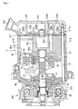
- As shown in
Figure 1 , a variable displacement swash plate compressor A comprises arotation shaft 10, arotor 11 fixed to therotation shaft 10, aswash plate 12 supported by therotation shaft 10 to be variable in inclination relative to therotation shaft 10. Theswash plate 12 is connected to therotor 11 by alinkage 13, which allows the inclination of theswash plate 12 to vary, so as to rotate synchronously with therotor 11 or therotation shaft 10.
Pistons 15 are anchored to theswash plate 12 through pairs ofshoes 14 slidably engaging the outer circumferential portion of theswash plate 12.
Therotor 11, thelinkage 13, theswash plate 12 and theshoes 14 form a motion converter for converting rotation of therotation shaft 10 to reciprocal motion of thepistons 15.
Thepistons 15 are inserted incylinder bores 16a formed in acylinder block 16.
Thecylinder bores 16a are circumferentially distanced from each other.
Afront housing 18 forms acrank chamber 17 for accommodating therotation shaft 10, therotor 11, thelinkage 13, theswash plate 12 and theshoes 14. Thefront housing 18 has a cylindrical form closed at one end.
One end of therotation shaft 10 passes through the closed end of thefront housing 18 to extend out of thefront housing 18. Aseal member 19 is disposed between thefront hosing 18 and the portion of therotation shaft 10 passing through thefront housing 18. - The
rotation shaft 10 is rotatably supported by a radial bearing 20 pressed in and fixed to the portion of the front housing through which the rotation shaft passes and a radial bearing 21 pressed in and fixed to acenter bore 16b formed in thecylinder block 16. Thecenter bore 16b extends to the longitudinal middle of thecylinder block 16. - Driving power is transmitted from an external power source to the said one end of the
rotation shaft 10 through anelectromagnetic clutch 26 mounted on thefront housing 18. The external power source is not shown inFigure 1 . - A
valve plate 27 is disposed opposite one end of thecylinder block 16. Thevalve plate 27 is provided withsuction holes 27a,discharge holes 27b, suction valves for closing thesuction holes 27a and discharge valves for closing thedischarge holes 27b.
Arear housing 28 is disposed opposite thevalve plate 27. Therear housing 28 is provided with asuction chamber 28a communicating with thecylinder bores 16a through thesuction holes 27a and the suction valves, and adischarge chamber 28b communicating with thecylinder bores 16a through the discharge valves and thedischarge holes 27b. Thesuction chamber 28a connects to an evaporator of a car air conditioner through asuction port 29 and thedischarge chamber 28b connects to a condenser of the car air conditioner through adischarge port 30. The car air conditioner, the evaporator and the condenser are not shown inFigure 1 . - A center
secondary discharge chamber 16c of cylindrical shape is formed in thecylinder block 16. The centersecondary discharge chamber 16c is disposed adjacent thecenter bore 16b and located closer to thevalve plate 27 than thecenter bore 16b. The centersecondary discharge chamber 16c extends to the aforementioned one end of thecylinder block 16 to communicate with thedischarge chamber 28b through an opening 27c formed in thevalve plate 27. As shown inFigures 1 and2 , a plurality of satellitesecondary discharge chambers 16d of cylindrical shape with small diameter are formed in thecylinder block 16. The satellitesecondary discharge chambers 16d are located radially outside the centersecondary discharge chamber 16c, circumferentially distanced from each other and located between thecylinder bores 16a. The satellitesecondary discharge chambers 16d extend to the aforementioned one end of thecylinder block 16 to communicate with thedischarge chamber 28b throughopenings 27d formed in thevalve plate 27.
Legs 28d are disposed in thedischarge chamber 28b in addition to thebulkhead 28c for separating thedischarge chamber 28b from thesuction chamber 28a to clamp thevalve plate 27 in cooperation with thecylinder block 16. - The
front housing 18, thecylinder block 16, thevalve plate 27 and therear housing 28 are assembled as a unitary body by throughbolts 31.
The variable displacement swash plate compressor A is provided with an air supply passage communicating thedischarge chamber 28b with thecrank chamber 17 and a displacement control valve for closing the air supply passage. The variable displacement swash plate compressor A is provided with an air exhaust passage communicating thecrank chamber 17 with thesuction chamber 28a and a restriction disposed in the air exhaust passage. The air supply passage, the displacement control valve, the air exhaust passage and the restriction are not shown inFigures 1 and2 . - In the variable displacement swash plate compressor A, driving power of the external power source not shown in
Figures 1 and2 is transmitted to therotation shaft 10 through theelectromagnetic clutch 26 and the rotation of therotation shaft 10 is transmitted to theswash plate 12 through therotor 11 and thelinkage 13. Rotation of theswash plate 12 causes reciprocal motion of the outer circumferential portion thereof in the direction of the longitudinal axis of therotation shaft 10. The reciprocal motion of the outer circumferential portion of theswash plate 12 is transmitted to thepistons 15 through theshoes 14 to cause reciprocal motion of thepistons 15 in thecylinder bores 16a. Refrigerant gas returned from the evaporator of the car air conditioner is sucked into the cylinder bores 16a through thesuction port 29, thesuction chamber 28a, the suction holes 27a and the suction valves. The refrigerant gas is compressed in the cylinder bores 16a and passes out of the compressor to the condenser of the car air conditioner through the discharge holes 27b, the discharge valves, thedischarge chamber 28b and thedischarge port 30.
The displacement control valve opens and closes the air supply passage between thedischarge chamber 28b and thecrank chamber 17 to start and stop the introduction of the discharge pressure to the crankchamber 17. Thus, the pressure in thecrank chamber 17 is controlled to control the inclination angle of theswash plate 12, thereby variably controlling the displacement of the compressor A. - When the compressed refrigerant gas discharges from the cylinder bores 16a to the
discharge chamber 28b, the refrigerant gas causes pulsation of discharge pressure. The pulsation of the discharge pressure propagates outside the compressor through thedischarge port 30 to resonate with various members close to the compressor, thereby causing compressor noise. However, in the variable displacement swash plate compressor A, the operation of thedischarge chamber 28b as an expansion muffler is enhanced to restrict the propagation of the pulsation of the discharge pressure outside the compressor because the centersecondary discharge chamber 16c and the plurality of the satellitesecondary discharge chambers 16d formed in thecylinder block 16 communicate with thedischarge chamber 28b through theopening 27c and theopenings 27d formed in thevalve plate 27 to increase the volume of thedischarge chamber 28b. As a result, the compressor noise decreases.
In the variable displacement swash plate compressor A, the secondary discharge chamber is not formed by a center cylindrical portion coaxial to the center bore and radial arm portions extending from the center cylindrical portion and located between the cylinder bores but by a centersecondary discharge chamber 16c adjacent the center bore 16b and a plurality of satellitesecondary discharge chambers 16d located radially outside the centersecondary discharge chamber 16c, circumferentially distanced from each other and located between the cylinder bores 16a. The secondary discharge chamber formed by the centersecondary discharge chamber 16c and the satellitesecondary discharge chambers 16d independent of the centersecondary discharge chamber 16c is simpler in structure and easier to produce than the secondary discharge chamber formed by the center cylindrical portion and the radial arm portions continuously extending from the center cylindrical portion. - When the
secondary discharge chambers discharge chamber 28b through theopenings valve plate 27, the balance of the pressure acting on thevalve plate 27 is liable to change, the force acting on thevalve plate 27 to push it in the direction of therear housing 28 is liable to become larger than the force acting on thevalve plate 27 to push it in the reverse direction, and thevalve plate 27 is liable to deform toward thedischarge chamber 28b at the center portion. When thelegs 28d provided in thedischarge chamber 28b as well as thebulkhead 28c for separating thedischarge chamber 28b from thesuction chamber 28a clamp thevalve plate 27 in cooperation with thecylinder block 16, the deformation of thevalve plate 27 is prevented. - In the following description, the same structures as in the first embodiment will be allotted the same reference numerals as in the first embodiment.
As shown inFigure 3 , a variable displacement swash plate compressor A comprises arotation shaft 10, arotor 11 fixed to therotation shaft 10, aswash plate 12 supported by therotation shaft 10 to be variable in inclination relative to therotation shaft 10. Theswash plate 12 is connected to therotor 11 by alinkage 13, which allows the inclination of theswash plate 12 to vary, so as to rotate synchronously with therotor 11 or therotation shaft 10.
Pistons 15 are anchored to theswash plate 12 through pairs ofshoes 14 slidably engaging the outer circumferential portion of theswash plate 12.
Therotor 11, thelinkage 13, theswash plate 12 and theshoes 14 form a motion converter for converting rotation of therotation shaft 10 to reciprocal motion of thepistons 15.
Thepistons 15 are inserted incylinder bores 16a formed in acylinder block 16. The cylinder bores 16a extend through thecylinder block 16.
Afront housing 18 forms a crankchamber 17 for accommodating therotation shaft 10, therotor 11, thelinkage 13, theswash plate 12 and theshoes 14. Thefront housing 18 has a cylindrical shape closed at one end.
One end of therotation shaft 10 passes through the closed end of thefront housing 18 to extend out of thefront housing 18. Aseal member 19 is disposed between the front hosing 18 and the portion of therotation shaft 10 passing through thefront housing 18. - The
rotation shaft 10 is rotatably supported by aradial bearing 20 pressed in and fixed to the portion of the front housing through which the rotation shaft passing and aradial bearing 21 pressed in and fixed to acenter bore 16b formed in thecylinder block 16. The center bore 16b passes through thecylinder block 16.
Therotation shaft 10 is clamped by athrust bearing 22 disposed between therotor 11 and thefront housing 18 and asupport member 23 disposed adjacent the other end of therotation shaft 10. The space between the other end of therotation shaft 10 and thesupport member 23 is controlled to a predetermined value by an adjustmember 24 screwed in the center bore 16b to locate therotation shaft 10 in the longitudinal direction.
The contact part between the head of the adjustmember 24 and the center bore 16b is sealed by an O-ring 25. - Driving power is transmitted from an external power source not shown in
Figure 3 to the said one end of therotation shaft 10 through an electromagnetic clutch 26 mounted on thefront housing 18. - A
valve plate 27 is disposed opposite one end of thecylinder block 27. Thevalve plate 27 is provided withsuction holes 27a, dischargeholes 27b, suction valves for closing the suction holes 27a and discharge valves for closing the discharge holes 27b.
Arear housing 28 is disposed opposite thevalve plate 27. Therear housing 28 is provided with asuction chamber 28a communicating with the cylinder bores 16a through the suction holes 27a and the suction valves and adischarge chamber 28b communicating with the cylinder bores 16a through the discharge valves and the discharge holes 27b. Thesuction chamber 28a connects to an evaporator of a car air conditioner through asuction port 29 and thedischarge chamber 28b connects to a condenser of the car air conditioner through adischarge port 30. The car air conditioner, the evaporator and the condenser are not shown inFigure 3 .
The portion of the center bore 16b closer to thevalve plate 27 than the adjustmember 24 communicates with thedischarge chamber 28 through anopening 27c formed in thevalve plate 27.
Legs 28d are disposed in thedischarge chamber 28b in addition to thebulkhead 28c for separating thedischarge chamber 28b from thesuction chamber 28a to clamp thevalve plate 27 in cooperation with thecylinder block 16. - The
front housing 18, thecylinder block 16, thevalve plate 27 and therear housing 28 are assembled as a unitary body by throughbolts 31.
The variable displacement swash plate compressor A' is provided with an air supply passage communicating thedischarge chamber 28b with thecrank chamber 17 and a displacement control valve for closing the air supply passage. The variable displacement swash plate compressor A' is provided with an air exhaust passage communicating thecrank chamber 17 with thesuction chamber 28a and a restriction disposed in the air exhaust passage. The air supply passage, the displacement control valve, the air exhaust passage and the restriction are not shown inFigure 3 . - In the variable displacement swash plate compressor A', driving power of the external power source not shown in
Figure 3 is transmitted to therotation shaft 10 through theelectromagnetic clutch 26 and the rotation of therotation shaft 10 is transmitted to theswash plate 12 through therotor 11 and thelinkage 13. Rotation of theswash plate 12 causes reciprocal motion of the outer circumferential portion thereof in the direction of the longitudinal axis of therotation shaft 10. The reciprocal motion of the outer circumferential portion of theswash plate 12 is transmitted to thepistons 15 through theshoes 14 to cause reciprocal motions of thepistons 15 in the cylinder bores 16a. Refrigerant gas returned from the evaporator of the car air conditioner is sucked into the cylinder bores 16a through thesuction port 29, thesuction chamber 28a, the suction holes 27a and the suction valves. The refrigerant gas is compressed in the cylinder bores 16a and passes out of the compressor to the condenser of the car air conditioner through the discharge holes 27b, the discharge valves, thedischarge chamber 28b and thedischarge port 30.
The displacement control valve opens and closes the air supply passage between thedischarge chamber 28b and thecrank chamber 17 to start and stop the introduction of the discharge pressure to the crankchamber 17. Thus, the pressure in thecrank chamber 17 is controlled to control the inclination angle of theswash plate 12, thereby variably controlling the displacement of the compressor. - When the compressed refrigerant gas discharges from the cylinder bores 16a to the
discharge chamber 28b, the refrigerant gas causes pulsation of discharge pressure. The pulsation of the discharge pressure propagates outside the compressor through thedischarge port 30 to resonate with various members disposed close to the compressor, thereby causing compressor noise. However, in the variable displacement swash plate compressor A', the operation of thedischarge chamber 28b as an expansion muffler is enhanced to restrict the propagation of the pulsation of the discharge pressure outside the compressor because the portion of the center bore 16b closer to thevalve plate 27 than the adjustmember 24 communicates with thedischarge chamber 28b through theopening 27c to increase the volume of thedischarge chamber 28b. As a result, the compressor noise decreases.
In the variable displacement swash plate compressor A', the contact part between the head of the adjustmember 24 and the center bore 16b is sealed by the O·ring 25. Therefore, the portion of the center bore 16b more distanced from thevalve plate 27 than the adjustmember 24 is prevented from communicating with the portion of the center bore 16b closer tovalve plate 27 than the adjustmember 24 through the threaded portion of the adjustmember 24, and thecrank chamber 17 does not communicate with thedischarge chamber 28b through the center bore 16b. Therefore, the displacement of the compressor A' is reliably controlled by opening and closing the air supply passage between the discharge chamber and the crank chamber. - When the portion of the center bore 16b closer to the
valve plate 27 than the adjustmember 24 communicates with thedischarge chamber 28b through theopenings 27c formed in thevalve plate 27, the balance of the pressure acting on thevalve plate 27 is liable to change, the force acting on thevalve plate 27 to push it in the direction of therear housing 28 is liable to become larger than the force acting on thevalve plate 27 to push it in the reverse direction, and thevalve plate 27 is liable to deform toward thedischarge chamber 28b at the center portion. When thelegs 28d provided in thedischarge chamber 28b as well as thebulkhead 28c for separating thedischarge chamber 28b from thesuction chamber 28a clamp thevalve plate 27 in cooperation with thecylinder block 16, the deformation of thevalve plate 27 is prevented. - It is possible to form a plurality of satellite bores like the satellite
secondary discharge chambers 16d in the first embodiment, which are located radially outside the center bore 16b, circumferentially distanced from each other and located between the cylinder bores 16a, in thecylinder block 16 and form openings like theopenings 27d in the first embodiment in thevalve plate 27 to communicate the satellite bores to thedischarge chamber 28b through the openings in the valve plate, in addition to communicating the portion of the center bore 16b closer to thevalve plate 27 than the adjustmember 24 with thedischarge chamber 28b through theopening 27c formed in thevalve plate 27.
In the aforementioned case, the volume of thedischarge chamber 28b further increases, the pulsation of the discharge pressure caused by the refrigerant gas discharging from the cylinder bores 16a to thedischarge chamber 28b further decreases and the compressor noise further decreases. - The present invention can be widely used in reciprocal compressors such as swash plate compressors, wobble plate compressors, etc.
-
-
Figure 1 is a sectional view of a reciprocal compressor in accordance with the first preferred embodiment of the present invention. -
Figure 2 is a view in the direction of arrows II-II inFigure 1 . -
Figure 3 is a sectional view of a reciprocal compressor in accordance with the second preferred embodiment of the present invention.
Claims (4)
- A reciprocal compressor comprising a rotation shaft, a motion converter for converting rotation to reciprocal motion, pistons driven by the rotation shaft through the motion converter to move reciprocally, a cylinder block provided with cylinder bores in which the pistons are inserted and a center bore in which one end of the rotation shaft is inserted, a valve plate provided with suction holes, discharge holes, suction valves for closing the suction holes and discharge valves for closing the discharge holes and disposed opposite one end of the cylinder block, and a rear housing provided with a suction chamber communicating with the cylinder bores through the suction holes and the suction valves and a discharge chamber communicating with the cylinder bores through the discharge valves and the discharge holes and disposed opposite the valve plate, wherein the cylinder bores are circumferentially distanced from each other, and the cylinder block is provided with a group of secondary discharge chambers which are located closer to the valve plate than the center bore to communicate with the discharge chamber through openings formed in the valve plate, and wherein the group of secondary discharge chambers comprises a center secondary discharge chamber adjacent the center bore, and a plurality of satellite secondary discharge chambers located radially outside the center secondary discharge chamber, circumferentially distanced from each other, and located between the cylinder bores, and each of the secondary discharge chambers communicates with the discharge chamber through the opening formed in the valve plate.
- A reciprocal compressor comprising a rotation shaft, a motion converter for converting rotation to reciprocal motion, pistons driven by the rotation shaft through the motion converter to move reciprocally, a cylinder block provided with cylinder bores in which the pistons are inserted and a center bore in which one end of the rotation shaft is inserted, a valve plate provided with suction holes, discharge holes, suction valves for closing the suction holes and discharge valves for closing the discharge holes and disposed opposite one end of the cylinder block, and a rear housing provided with a suction chamber communicating with the cylinder bores through the suction holes and the suction valves and a discharge chamber communicating with the cylinder bores through the discharge valves and the discharge holes and disposed opposite the valve plate, wherein an adjust member is screwed in the center bore to locate the rotation shaft in the longitudinal direction, the center bore communicates with the discharge chamber at a portion closer to the valve plate than the adjust member through an opening formed in the valve plate, and the contact part between the adjust member and the center bore is sealed by a seal member.
- A reciprocal compressor of claim 2, wherein the cylinder block is provided with a plurality of satellite bores located radially outside the center bore, circumferentially distanced from each other, and located between the cylinder bores, and each of the satellite bores communicates with the discharge chamber through an opening formed in the valve plate.
- A reciprocal compressor of anyone of claims 1 to 3, wherein not only a bulkhead for separating the discharge chamber from the suction chamber but also legs provided in the discharge chamber clamp the valve plate in cooperation with the cylinder block.
Applications Claiming Priority (2)
| Application Number | Priority Date | Filing Date | Title |
|---|---|---|---|
| JP2005273042A JP4663462B2 (en) | 2005-09-21 | 2005-09-21 | Reciprocating compressor |
| PCT/JP2006/314546 WO2007034621A1 (en) | 2005-09-21 | 2006-07-24 | Reciprocating compressor |
Publications (2)
| Publication Number | Publication Date |
|---|---|
| EP1947336A1 true EP1947336A1 (en) | 2008-07-23 |
| EP1947336A4 EP1947336A4 (en) | 2008-12-03 |
Family
ID=37888676
Family Applications (1)
| Application Number | Title | Priority Date | Filing Date |
|---|---|---|---|
| EP06781468A Withdrawn EP1947336A4 (en) | 2005-09-21 | 2006-07-24 | Reciprocating compressor |
Country Status (5)
| Country | Link |
|---|---|
| US (1) | US20090238698A1 (en) |
| EP (1) | EP1947336A4 (en) |
| JP (1) | JP4663462B2 (en) |
| CN (1) | CN101268277A (en) |
| WO (1) | WO2007034621A1 (en) |
Families Citing this family (3)
| Publication number | Priority date | Publication date | Assignee | Title |
|---|---|---|---|---|
| JP5915576B2 (en) * | 2013-03-27 | 2016-05-11 | 株式会社豊田自動織機 | Piston type swash plate compressor |
| JP6189077B2 (en) * | 2013-04-23 | 2017-08-30 | 三菱重工オートモーティブサーマルシステムズ株式会社 | Housing and manufacturing method thereof |
| CN103994047B (en) * | 2014-05-26 | 2016-09-07 | 合肥达因汽车空调有限公司 | A kind of swash-plate-type compressor |
Family Cites Families (12)
| Publication number | Priority date | Publication date | Assignee | Title |
|---|---|---|---|---|
| JPH0341101Y2 (en) * | 1988-03-23 | 1991-08-29 | ||
| IT1225173B (en) * | 1988-07-15 | 1990-11-02 | Esam Spa | VOLUMETRIC ROTARY SUCTION-BLOWER MACHINE |
| DE4493590T1 (en) * | 1993-05-21 | 1995-06-01 | Toyoda Automatic Loom Works | Compressor with reciprocating pistons |
| JP3203888B2 (en) * | 1993-05-21 | 2001-08-27 | 株式会社豊田自動織機製作所 | Reciprocating compressor |
| JPH07269462A (en) * | 1994-03-31 | 1995-10-17 | Toyota Autom Loom Works Ltd | Reciprocating compressor |
| JPH08200218A (en) * | 1995-01-31 | 1996-08-06 | Toyota Autom Loom Works Ltd | Reciprocation type compressor |
| JPH08261146A (en) * | 1995-03-20 | 1996-10-08 | Toyota Autom Loom Works Ltd | Reciprocating piston type compressor |
| US6068453A (en) * | 1997-06-30 | 2000-05-30 | Halla Climate Control Corp. | Reciprocating piston type refrigerant compressor |
| JP2001012345A (en) * | 1999-06-28 | 2001-01-16 | Sanden Corp | Variable displacement compressor |
| JP3744861B2 (en) * | 2002-02-15 | 2006-02-15 | 株式会社デンソー | Compressor |
| DE10250591B4 (en) * | 2001-11-02 | 2018-01-18 | Denso Corporation | Compressor with guide grooves as connecting mechanism between drive pulley and shaft |
| KR100659570B1 (en) * | 2003-02-18 | 2006-12-19 | 한라공조주식회사 | compressor |
-
2005
- 2005-09-21 JP JP2005273042A patent/JP4663462B2/en not_active Expired - Fee Related
-
2006
- 2006-07-24 EP EP06781468A patent/EP1947336A4/en not_active Withdrawn
- 2006-07-24 CN CNA2006800346037A patent/CN101268277A/en active Pending
- 2006-07-24 US US12/067,628 patent/US20090238698A1/en not_active Abandoned
- 2006-07-24 WO PCT/JP2006/314546 patent/WO2007034621A1/en not_active Ceased
Also Published As
| Publication number | Publication date |
|---|---|
| US20090238698A1 (en) | 2009-09-24 |
| JP4663462B2 (en) | 2011-04-06 |
| CN101268277A (en) | 2008-09-17 |
| JP2007085209A (en) | 2007-04-05 |
| WO2007034621A1 (en) | 2007-03-29 |
| EP1947336A4 (en) | 2008-12-03 |
Similar Documents
| Publication | Publication Date | Title |
|---|---|---|
| EP1942274B1 (en) | Compressor | |
| JP4606433B2 (en) | Variable capacity swash plate compressor | |
| EP1491769B1 (en) | A device having a pulsation reducing structure and a passage forming body | |
| US5533871A (en) | Single-headed-piston-type swash-plate compressor having pulsation damping system | |
| EP0623749B1 (en) | Rotary gas compressor | |
| US6045342A (en) | Refrigerant compressor | |
| EP2441957A1 (en) | Reciprocating compressor | |
| US5704769A (en) | Noise suppressing mechanism in piston-type compressor | |
| US6540488B2 (en) | Slant plate-type variable displacement compressors with capacity control mechanisms | |
| EP2037122A1 (en) | Compressor | |
| US20090238698A1 (en) | Reciprocal Compressor | |
| EP1394410B1 (en) | Compressor having reduced pressure pulsation | |
| EP1617078B1 (en) | Refrigerant suction structures for compressors | |
| US20030095876A1 (en) | Swash plate type compressor | |
| KR101379610B1 (en) | Variable displacement swash plate type compressor | |
| WO2007086261A1 (en) | Variable displacement-type clutchless compressor | |
| KR100329158B1 (en) | Apparatus for relieving start shock in compressors | |
| JP6618343B2 (en) | Compressor | |
| CN111749866B (en) | Piston type compressor | |
| KR101541917B1 (en) | Variable displacement swash plate type compressor | |
| JP2006077731A (en) | Reciprocating compressor | |
| JP7120103B2 (en) | piston compressor | |
| US20010043866A1 (en) | Electric compressor | |
| JP2014125994A (en) | Piston type compressor | |
| EP1795750A1 (en) | Piston compressor |
Legal Events
| Date | Code | Title | Description |
|---|---|---|---|
| PUAI | Public reference made under article 153(3) epc to a published international application that has entered the european phase |
Free format text: ORIGINAL CODE: 0009012 |
|
| 17P | Request for examination filed |
Effective date: 20080312 |
|
| AK | Designated contracting states |
Kind code of ref document: A1 Designated state(s): DE FR |
|
| DAX | Request for extension of the european patent (deleted) | ||
| RBV | Designated contracting states (corrected) |
Designated state(s): DE FR |
|
| A4 | Supplementary search report drawn up and despatched |
Effective date: 20081103 |
|
| RIC1 | Information provided on ipc code assigned before grant |
Ipc: F04B 53/00 20060101ALI20081028BHEP Ipc: F04B 39/00 20060101AFI20070531BHEP Ipc: F04B 27/08 20060101ALI20081028BHEP |
|
| 17Q | First examination report despatched |
Effective date: 20090206 |
|
| STAA | Information on the status of an ep patent application or granted ep patent |
Free format text: STATUS: THE APPLICATION IS DEEMED TO BE WITHDRAWN |
|
| 18D | Application deemed to be withdrawn |
Effective date: 20090616 |