EP1946861A1 - Closing device and closing method - Google Patents
Closing device and closing method Download PDFInfo
- Publication number
- EP1946861A1 EP1946861A1 EP08000307A EP08000307A EP1946861A1 EP 1946861 A1 EP1946861 A1 EP 1946861A1 EP 08000307 A EP08000307 A EP 08000307A EP 08000307 A EP08000307 A EP 08000307A EP 1946861 A1 EP1946861 A1 EP 1946861A1
- Authority
- EP
- European Patent Office
- Prior art keywords
- die
- core
- pipe
- tubular body
- closing
- Prior art date
- Legal status (The legal status is an assumption and is not a legal conclusion. Google has not performed a legal analysis and makes no representation as to the accuracy of the status listed.)
- Granted
Links
Images


Classifications
-
- B—PERFORMING OPERATIONS; TRANSPORTING
- B21—MECHANICAL METAL-WORKING WITHOUT ESSENTIALLY REMOVING MATERIAL; PUNCHING METAL
- B21D—WORKING OR PROCESSING OF SHEET METAL OR METAL TUBES, RODS OR PROFILES WITHOUT ESSENTIALLY REMOVING MATERIAL; PUNCHING METAL
- B21D41/00—Application of procedures in order to alter the diameter of tube ends
- B21D41/04—Reducing; Closing
- B21D41/045—Closing
Definitions
- This invention relates to a closing device and a closing method.
- a closing process for closing an open end portion of a pipe between a die and a core by heating and rotating the pipe and then pressing the die against the pipe open end portion while the core is inserted into the pipe is known as a method of closing an open end portion of a metallic pipe (see JP 2005-342725A ).
- This invention has been designed in consideration of this problem, and it is an object thereof to provide a closing device and a closing method with which processing can be performed with stability immediately after the start of the processing.
- this invention provides a closing device that closes an open end portion of a tubular body using a die by moving the rotating tubular body and the die relative to each other.
- the closing device comprises first heating means that heat the tubular body during a closing process, and second heating means that heat the die, wherein the die is preheated by the second heating means at the start of the closing process, and the closing process is begun when a temperature difference between the die and the tubular body is small.
- FIG. 1 is a plan view showing a closing device 100 according to an embodiment of this invention.
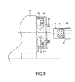
- FIG. 2 is a partially enlarged view showing the closing device 100 in a standby state prior to processing.
- FIGs. 3A and 3B are views showing procedures of a preliminary heating process performed on a die and a core.
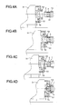
- FIGs. 4A to 4D are views showing procedures of the closing process.
- FIGs. 1 and 2 a closing device 100 serving as an embodiment of this invention will be described.
- the closing device 100 is a device for forming a pipe having a bottom by closing an open end portion of a pipe 1 constituted by a metallic tubular body.
- the closing device 100 closes the pipe open end portion by pressing a die 2 against the pipe open end while heating and rotating the pipe 1, thereby subjecting the pipe 1 to plastic deformation.
- An outer peripheral surface of the pipe 1 is gripped by a chuck spindle 20 disposed near a central portion of the closing device 100.
- the chuck spindle 20 rotates (spins) the gripped pipe 1 about its axis.
- a die 2 has a die cavity 2a in the shape of a bottom portion formed on the pipe 1 following a closing process, and is disposed so as to face the pipe 1.
- the die 2 can be rotated (spun) and moved in an axial direction of the pipe 1 by a die driving mechanism 30.
- the die driving mechanism 30 comprises a die support base 31 that supports a shaft (not shown), having an end portion to which the die 2 is attached, rotatably via a bearing, a motor 32 that rotates the die 2 via the shaft, a power transmission mechanism 33 that transmits the rotation of the motor 32 to the shaft, and a one-way clutch (not shown) that inputs torque into the shaft from the power transmission mechanism 33 and blocks torque input into the power transmission mechanism 33 from the shaft.
- the die 2 rotates when the motor 32 is driven, and when the die 2 is pressed against the pipe 1, which rotates at a higher speed than the die 2, the die 2 rotates in subordination to the pipe 1 due to the action of the one-way clutch.
- the die driving mechanism 30 further comprises a sliding table 35 carrying the die support base 31, a pair of guide rails 36 that extend in the axial direction of the pipe 1 and guide the sliding table 35, and a motor 38 having an output shaft to which a ball screw 37 screwed to the sliding table 35 is connected.
- the sliding table 35 moves along the guide rails 36 when the motor 38 is driven, whereby the die 2 can move in a direction toward the pipe 1 or a direction away from the pipe 1. Hence, by driving the motor 38, the die 2 can be pressed against the open end portion of the pipe 1.
- a tip end of the core 3 takes a spherical form defining a rear surface shape of the bottom portion to be formed on the pipe 1.
- the core 3 is capable of rotating (spinning) and can be moved in the axial direction of the pipe 1 by a core driving mechanism 40.
- the core driving mechanism 40 comprises a rod 41 connected to a base end portion of the core 3 and extending coaxially with the pipe 1, a support 42 that supports a base end side of the rod 41 rotatably via a bearing, and a hydraulic cylinder 43 that moves the support 42 in the axial direction of the pipe 1.
- the core 3 on the tip end of the rod 41 is inserted into the hollow portion of the pipe 1. Further, when the core 3 comes into contact with the rotating pipe 1 during the closing process, the core 3 rotates (spins) in subordination to the pipe 1.
- a ring-shaped bracket 52 is attached to a tip end of the die support base 31 via a tubular body 51.
- the die 2 is disposed inside the tubular body 51, and the pipe 1 is capable of penetrating an inner periphery of the bracket 52 to come into contact with the die 2.
- a high-frequency induction heating coil 53 serving as first heating means is attached in ring form to a front surface (the pipe 1 side) of the bracket 52.
- the high-frequency induction heating coil 53 heats both the pipe 1 and the core 3.
- a high-frequency induction heating coil 54 serving as second heating means is attached in ring form to a rear surface (the die 2 side) of the bracket 52 so as to surround the die 2.
- the high-frequency induction heating coil 54 heats the die 2.
- FIG. 3 is a view showing procedures of a preliminary heating process performed on the die 2 and the core 3
- FIG. 4 is a view showing procedures of the closing process.
- preliminary heating is performed on the die 2 in the state shown in FIG. 3A .
- Preliminary heating of the die 2 is performed by electrifying the high-frequency induction heating coil 54.
- the core 3 is caused to advance by driving the core driving mechanism 40 until the core 3 protrudes from an open end of the chuck spindle 20 and is disposed inside the high-frequency induction heating coil 53. In this state, preliminary heating is performed on the core 3. Preliminary heating of the core 3 is performed by electrifying the high-frequency induction heating coil 53.
- preliminary heating can be achieved in a short time period of approximately 1 or 2 minutes in relation to the die 2 and approximately 1 or 2 seconds in relation to the core 3.
- the pipe 1 is gripped by the chuck spindle 20 and the core 3 is inserted into the hollow portion of the pipe 1. Then, by driving the chuck spindle 20 and the die driving mechanism 30, the pipe 1 and the die 2 are rotated.
- the state shown in FIG. 4A corresponds to a standby position before the start of the process. It should be noted that the core 3 is held in this position from the start to the end of the process.
- the die support base 31 and the bracket 52 are caused to advance by driving the die driving mechanism 30.
- the high-frequency induction heating coil 53 is disposed on the outer periphery of the pipe 1.
- the state shown in FIG. 4B corresponds to a heating start position for starting to heat the pipe 1, and heating of the pipe 1 is begun by electrifying the high-frequency induction heating coil 53.
- the high-frequency induction heating coil 53 is caused to retreat along the pipe 1, thereby heating the pipe 1.
- the state shown in FIG. 4C corresponds to a heating end position in which heating of the pipe 1 ends.
- both the core 3 and the pipe 1 are heated by the high-frequency induction heating coil 53.
- the end portion of the heated pipe 1 is subjected to plastic deformation in accordance with the shape of the die cavity in the die 2, and comes into contact with the core 3 inserted into the pipe 1.
- the pipe 1 is processed between the die 2 and the core 3 such that the open end portion of the pipe 1 is closed and formed into a bottom portion. In this manner, closing is performed on the pipe 1.
- the die 2 and core 3 are preheated, and therefore the heat that is applied to the pipe 1 is unlikely to be transferred to the die 2 and core 3.
- the pipe 1 exhibits a favorable deformation characteristic. If the die 2 and core 3 are not preheated during processing of the pipe 1, a large temperature difference occurs between the pipe 1 and the die 2 and core 3. As a result, the heat applied to the pipe 1 is transferred to the die 2 and core 3 during the process, and in the worst-case scenario, the bottom portion is not formed, leaving a hole in the pipe 1.
- closing can be begun in a state where the temperature difference between the pipe 1 and the die 2 and core 3 is small by preheating the die 2 and core 3 at the start of the closing process, and therefore stable processing can be performed immediately after the beginning of the closing process.
- the need to discard the pipes 1 that are manufactured at the beginning of the closing process is eliminated, leading to an improvement in production efficiency.
- procedures described above are procedures executed when processing is begun after the closing device has been halted for a fixed time period, or in other words when the die 2 and core 3 are cool, and once the temperature of the die 2 and core 3 has risen, the closing process shown in FIG. 4 is repeated omitting the preliminary heating process shown in FIG. 3 .
- processing is performed using the die 2 and the core 3, but the processing may be performed using the die 2 alone.
- the die 2 is moved relative to the pipe 1, but the processing may be performed by moving the pipe 1 relative to the die 2.
- the pipe 1 can be processed as long as the pipe 1 and the die 2 can be moved relative to each other.
- two high-frequency induction heating coils are provided as the heating means, but the pipe 1, the die 2 and the core 3 may all be heated by a single high-frequency induction heating coil.
- the pipe 1, die 2 and core 3 are heated by the high-frequency induction heating coil 53 attached to the front surface of the bracket 52 alone, heating is performed on the pipe 1 and core 3 in the manner described above, and the die 2 can be heated by the high-frequency induction heating coil 53 by making the die 2 capable of advancing and retreating relative to the die support base 31.
- high-frequency induction heating is used as the heating means, but any device that is capable of applying heat, such as a burner or an industrial drier, may be used as the heating means for heating the pipe 1, die 2 and core 3.
Landscapes
- Engineering & Computer Science (AREA)
- Mechanical Engineering (AREA)
- Shaping Metal By Deep-Drawing, Or The Like (AREA)
- Moulds For Moulding Plastics Or The Like (AREA)
- Closing Of Containers (AREA)
Abstract
Description
- This invention relates to a closing device and a closing method.
- A closing process for closing an open end portion of a pipe between a die and a core by heating and rotating the pipe and then pressing the die against the pipe open end portion while the core is inserted into the pipe is known as a method of closing an open end portion of a metallic pipe (see
JP 2005-342725A - When pipes are processed continuously in a closing device, the heat that is applied to the pipes causes the temperature of the die and core to rise, and therefore the heat applied to the pipe is unlikely to be transferred to the die and core.
- However, at the beginning of the closing process, the die and core are cool, and therefore, if the process is begun in this state, the heat of the pipe is transferred to the die and core, making the pipe closing process unstable.
- As a result, it is sometimes necessary to discard several pipes manufactured immediately after the start of the closing process.
- This invention has been designed in consideration of this problem, and it is an object thereof to provide a closing device and a closing method with which processing can be performed with stability immediately after the start of the processing.
- In order to achieve above object, this invention provides a closing device that closes an open end portion of a tubular body using a die by moving the rotating tubular body and the die relative to each other. The closing device comprises first heating means that heat the tubular body during a closing process, and second heating means that heat the die, wherein the die is preheated by the second heating means at the start of the closing process, and the closing process is begun when a temperature difference between the die and the tubular body is small.
-
FIG. 1 is a plan view showing aclosing device 100 according to an embodiment of this invention. -
FIG. 2 is a partially enlarged view showing theclosing device 100 in a standby state prior to processing. -
FIGs. 3A and 3B are views showing procedures of a preliminary heating process performed on a die and a core. -
FIGs. 4A to 4D are views showing procedures of the closing process. - An embodiment of this invention will be described below with reference to the drawings.
- Referring to
FIGs. 1 and2 , aclosing device 100 serving as an embodiment of this invention will be described. - First, the overall structure of the
closing device 100 will be described. - The
closing device 100 is a device for forming a pipe having a bottom by closing an open end portion of a pipe 1 constituted by a metallic tubular body. Theclosing device 100 closes the pipe open end portion by pressing adie 2 against the pipe open end while heating and rotating the pipe 1, thereby subjecting the pipe 1 to plastic deformation. - An outer peripheral surface of the pipe 1 is gripped by a
chuck spindle 20 disposed near a central portion of theclosing device 100. Thechuck spindle 20 rotates (spins) the gripped pipe 1 about its axis. - A
die 2 has adie cavity 2a in the shape of a bottom portion formed on the pipe 1 following a closing process, and is disposed so as to face the pipe 1. - The die 2 can be rotated (spun) and moved in an axial direction of the pipe 1 by a
die driving mechanism 30. - The die
driving mechanism 30 comprises adie support base 31 that supports a shaft (not shown), having an end portion to which thedie 2 is attached, rotatably via a bearing, amotor 32 that rotates thedie 2 via the shaft, apower transmission mechanism 33 that transmits the rotation of themotor 32 to the shaft, and a one-way clutch (not shown) that inputs torque into the shaft from thepower transmission mechanism 33 and blocks torque input into thepower transmission mechanism 33 from the shaft. - By means of these constitutions in the
die driving mechanism 30, thedie 2 rotates when themotor 32 is driven, and when thedie 2 is pressed against the pipe 1, which rotates at a higher speed than thedie 2, thedie 2 rotates in subordination to the pipe 1 due to the action of the one-way clutch. - The die
driving mechanism 30 further comprises a sliding table 35 carrying thedie support base 31, a pair ofguide rails 36 that extend in the axial direction of the pipe 1 and guide the sliding table 35, and amotor 38 having an output shaft to which aball screw 37 screwed to the sliding table 35 is connected. - By means of these constitutions in the
die driving mechanism 30, the sliding table 35 moves along theguide rails 36 when themotor 38 is driven, whereby thedie 2 can move in a direction toward the pipe 1 or a direction away from the pipe 1. Hence, by driving themotor 38, thedie 2 can be pressed against the open end portion of the pipe 1. - A
core 3 disposed in a hollow portion of the pipe 1 and capable of moving relative to the pipe 1, which closes the open end portion of the pipe 1 on the opposite side of thedie 2, is disposed to the rear of thechuck spindle 20. A tip end of thecore 3 takes a spherical form defining a rear surface shape of the bottom portion to be formed on the pipe 1. - The
core 3 is capable of rotating (spinning) and can be moved in the axial direction of the pipe 1 by acore driving mechanism 40. - The
core driving mechanism 40 comprises arod 41 connected to a base end portion of thecore 3 and extending coaxially with the pipe 1, asupport 42 that supports a base end side of therod 41 rotatably via a bearing, and ahydraulic cylinder 43 that moves thesupport 42 in the axial direction of the pipe 1. - When the
hydraulic cylinder 43 performs an expansion/contraction operation, thecore 3 on the tip end of therod 41 is inserted into the hollow portion of the pipe 1. Further, when thecore 3 comes into contact with the rotating pipe 1 during the closing process, thecore 3 rotates (spins) in subordination to the pipe 1. - Next, referring to
FIG. 2 , a structure on the periphery of the die 2 will be described. - A ring-
shaped bracket 52 is attached to a tip end of thedie support base 31 via atubular body 51. The die 2 is disposed inside thetubular body 51, and the pipe 1 is capable of penetrating an inner periphery of thebracket 52 to come into contact with the die 2. - A high-frequency
induction heating coil 53 serving as first heating means is attached in ring form to a front surface (the pipe 1 side) of thebracket 52. The high-frequency induction heating coil 53 heats both the pipe 1 and thecore 3. - Further, a high-frequency
induction heating coil 54 serving as second heating means is attached in ring form to a rear surface (thedie 2 side) of thebracket 52 so as to surround thedie 2. The high-frequency induction heating coil 54 heats the die 2. - Next, referring to
FIGs. 3 and4 , each step of a closing method employing theclosing device 100 will be described in sequence.FIG. 3 is a view showing procedures of a preliminary heating process performed on thedie 2 and thecore 3, andFIG. 4 is a view showing procedures of the closing process. - The operations of the various members to be described below are controlled automatically by a controller (not shown) installed in the
closing device 100. It should be noted that the processing procedures to be described below are procedures executed when processing is begun after the closing device has been halted for a fixed time period. - First, preliminary heating is performed on the
die 2 in the state shown inFIG. 3A . Preliminary heating of the die 2 is performed by electrifying the high-frequencyinduction heating coil 54. - Next, as shown in
FIG. 3B , thecore 3 is caused to advance by driving thecore driving mechanism 40 until thecore 3 protrudes from an open end of thechuck spindle 20 and is disposed inside the high-frequencyinduction heating coil 53. In this state, preliminary heating is performed on thecore 3. Preliminary heating of thecore 3 is performed by electrifying the high-frequencyinduction heating coil 53. - In this manner, the
die 2 and thecore 3 are subjected to preliminary heating. When performed through high-frequency induction heating, preliminary heating can be achieved in a short time period of approximately 1 or 2 minutes in relation to thedie 2 and approximately 1 or 2 seconds in relation to thecore 3. - As shown in
FIG. 4A , when preliminary heating of thedie 2 andcore 3 is complete, the pipe 1 is gripped by thechuck spindle 20 and thecore 3 is inserted into the hollow portion of the pipe 1. Then, by driving thechuck spindle 20 and thedie driving mechanism 30, the pipe 1 and thedie 2 are rotated. The state shown inFIG. 4A corresponds to a standby position before the start of the process. It should be noted that thecore 3 is held in this position from the start to the end of the process. - Next, as shown in
FIG. 4B , thedie support base 31 and thebracket 52 are caused to advance by driving thedie driving mechanism 30. As a result, the high-frequencyinduction heating coil 53 is disposed on the outer periphery of the pipe 1. The state shown inFIG. 4B corresponds to a heating start position for starting to heat the pipe 1, and heating of the pipe 1 is begun by electrifying the high-frequencyinduction heating coil 53. - Then, by driving the
die driving mechanism 30, the high-frequencyinduction heating coil 53 is caused to retreat along the pipe 1, thereby heating the pipe 1. The state shown inFIG. 4C corresponds to a heating end position in which heating of the pipe 1 ends. Thus, both thecore 3 and the pipe 1 are heated by the high-frequencyinduction heating coil 53. - Next, closing is performed on the pipe 1. As shown in
FIG. 4D , thedie 2 is caused to advance toward the pipe 1 by driving thedie driving mechanism 30 until thedie 2 is pressed against the open end portion of the pipe 1. - As a result, the end portion of the heated pipe 1 is subjected to plastic deformation in accordance with the shape of the die cavity in the
die 2, and comes into contact with thecore 3 inserted into the pipe 1. Thus, the pipe 1 is processed between thedie 2 and thecore 3 such that the open end portion of the pipe 1 is closed and formed into a bottom portion. In this manner, closing is performed on the pipe 1. - In this process, the
die 2 andcore 3 are preheated, and therefore the heat that is applied to the pipe 1 is unlikely to be transferred to thedie 2 andcore 3. Hence, during the process, the pipe 1 exhibits a favorable deformation characteristic. If thedie 2 andcore 3 are not preheated during processing of the pipe 1, a large temperature difference occurs between the pipe 1 and thedie 2 andcore 3. As a result, the heat applied to the pipe 1 is transferred to thedie 2 andcore 3 during the process, and in the worst-case scenario, the bottom portion is not formed, leaving a hole in the pipe 1. - According to the embodiment described above, closing can be begun in a state where the temperature difference between the pipe 1 and the
die 2 andcore 3 is small by preheating thedie 2 andcore 3 at the start of the closing process, and therefore stable processing can be performed immediately after the beginning of the closing process. Hence, the need to discard the pipes 1 that are manufactured at the beginning of the closing process is eliminated, leading to an improvement in production efficiency. - It should be noted that the procedures described above are procedures executed when processing is begun after the closing device has been halted for a fixed time period, or in other words when the
die 2 andcore 3 are cool, and once the temperature of thedie 2 andcore 3 has risen, the closing process shown inFIG. 4 is repeated omitting the preliminary heating process shown inFIG. 3 . - This invention is not limited to the embodiment described above, and may be subjected to various modifications within the scope of the technical spirit thereof.
- For example, in the embodiment described above, processing is performed using the
die 2 and thecore 3, but the processing may be performed using thedie 2 alone. - Further, in the embodiment described above, the
die 2 is moved relative to the pipe 1, but the processing may be performed by moving the pipe 1 relative to thedie 2. In other words, the pipe 1 can be processed as long as the pipe 1 and thedie 2 can be moved relative to each other. - Further, in the embodiment described above, two high-frequency induction heating coils (53, 54) are provided as the heating means, but the pipe 1, the
die 2 and thecore 3 may all be heated by a single high-frequency induction heating coil. For example, when the pipe 1, die 2 andcore 3 are heated by the high-frequencyinduction heating coil 53 attached to the front surface of thebracket 52 alone, heating is performed on the pipe 1 andcore 3 in the manner described above, and thedie 2 can be heated by the high-frequencyinduction heating coil 53 by making thedie 2 capable of advancing and retreating relative to thedie support base 31. - Furthermore, in the embodiment described above, high-frequency induction heating is used as the heating means, but any device that is capable of applying heat, such as a burner or an industrial drier, may be used as the heating means for heating the pipe 1, die 2 and
core 3.
Claims (7)
- A closing device (100) that closes an open end portion of a tubular body (1) using a die (2) by moving the rotating tubular body (1) and the die (2) relative to each other, comprising:first heating means (53) that heat the tubular body (1) during a closing process; andsecond heating means (54) that heat the die (2),wherein the die (2) is preheated by the second heating means (54) at the start of the closing process, and the closing process is begun when a temperature difference between the die (2) and the tubular body (1) is small.
- The closing device (100) as defined in Claim 1, further comprising a core (3) that is inserted into the tubular body (1) and closes the open end portion of the tubular body (1) on an opposite side of the die (2),
wherein the first heating means (53) are also capable of heating the core (3), and
the core (3) and the die (2) are preheated by the first heating means (53) and the second heating means (54) respectively at the start of the closing process, and the closing process is begun when a temperature difference between the tubular body (1) and the core (3) and die (2) is small. - The closing device (100) as defined in Claim 2, further comprising a core moving mechanism (40) that moves the core (3) in an axial direction of the tubular body (1),
wherein the first heating means (53) are a high-frequency induction heating coil (53), and
the core (3) is disposed inside the high-frequency induction heating coil (53) by the core moving mechanism (40), where high-frequency induction heating is applied thereto. - The closing device (100) as defined in any one of Claim 1 through Claim 3, wherein the first heating means (53) and the second heating means (54) are identical heating means.
- A closing method in which an open end portion of a tubular body (1) is closed using a die (2) by moving the rotating tubular body (1) and the die (2) relative to each other, comprising:preheating the die (2) at the start of a closing process, andsubsequently heating the tubular body (1) and performing the closing process.
- The closing method as defined in Claim 5, comprising:preheating the die (2) and preheating a core (3) inserted into the tubular body (1) at the start of the closing process, andsubsequently heating the tubular body (1) and performing the closing process to close the open end portion of the tubular body (1) between the die (2) and the core (3).
- The closing method as defined in Claim 6, wherein preheating of the core (3) is performed by moving the core (3) in an axial direction of the tubular body (1) such that the core (3) is disposed in a high-frequency induction heating coil (53), and electrifying the high-frequency induction heating coil (53).
Applications Claiming Priority (1)
| Application Number | Priority Date | Filing Date | Title |
|---|---|---|---|
| JP2007007806A JP5139683B2 (en) | 2007-01-17 | 2007-01-17 | Closing processing apparatus and closing processing method |
Publications (2)
| Publication Number | Publication Date |
|---|---|
| EP1946861A1 true EP1946861A1 (en) | 2008-07-23 |
| EP1946861B1 EP1946861B1 (en) | 2010-07-21 |
Family
ID=39345469
Family Applications (1)
| Application Number | Title | Priority Date | Filing Date |
|---|---|---|---|
| EP08000307A Not-in-force EP1946861B1 (en) | 2007-01-17 | 2008-01-09 | Closing device and closing method |
Country Status (5)
| Country | Link |
|---|---|
| US (1) | US20080168819A1 (en) |
| EP (1) | EP1946861B1 (en) |
| JP (1) | JP5139683B2 (en) |
| DE (1) | DE602008001805D1 (en) |
| ES (1) | ES2345687T3 (en) |
Cited By (1)
| Publication number | Priority date | Publication date | Assignee | Title |
|---|---|---|---|---|
| CN102284615A (en) * | 2011-06-20 | 2011-12-21 | 张家港金鸿顺机械工业有限公司 | Forming device for pipe end forming die |
Families Citing this family (5)
| Publication number | Priority date | Publication date | Assignee | Title |
|---|---|---|---|---|
| JP2010234425A (en) * | 2009-03-31 | 2010-10-21 | Hitachi Automotive Systems Ltd | Closing processing apparatus and closing processing method |
| CN104511543B (en) * | 2013-09-30 | 2017-03-15 | 珠海格力电器股份有限公司 | Sealing device for pipe fitting |
| MX2018011712A (en) * | 2016-03-30 | 2018-12-19 | Nhk Spring Co Ltd | Hollow coil spring, and suspension device for vehicle. |
| EP3438495B1 (en) | 2016-03-30 | 2022-01-12 | NHK Spring Co., Ltd. | Hollow spring member |
| JP7215343B2 (en) * | 2019-06-07 | 2023-01-31 | 日本製鉄株式会社 | METHOD FOR MANUFACTURING TUBE MEMBER WITH CLOSED END |
Citations (4)
| Publication number | Priority date | Publication date | Assignee | Title |
|---|---|---|---|---|
| DE19714753A1 (en) | 1997-04-10 | 1998-10-15 | Gfu Ges Fuer Umformung Und Mas | Shaping closed container base |
| JP2003200241A (en) | 2001-12-27 | 2003-07-15 | Tokico Ltd | Pipe end closing method and apparatus |
| JP2005342725A (en) | 2004-05-31 | 2005-12-15 | Hitachi Ltd | Bottomed tube and manufacturing method thereof |
| JP2006281236A (en) | 2005-03-31 | 2006-10-19 | Kayaba Ind Co Ltd | Closing processing method and closing processing machine |
Family Cites Families (5)
| Publication number | Priority date | Publication date | Assignee | Title |
|---|---|---|---|---|
| USRE26457E (en) * | 1968-09-17 | Edgecombe etal hot drawing tubes | ||
| US2309561A (en) * | 1941-01-30 | 1943-01-26 | Charles Greenblatt | Method of treating metallic bodies |
| US3475786A (en) * | 1966-12-30 | 1969-11-04 | Medical Supply Co | Tube closing machine |
| JP2548799B2 (en) * | 1989-05-29 | 1996-10-30 | 日鋼特機株式会社 | Tube diameter reducing machine |
| US6742236B1 (en) * | 1999-09-20 | 2004-06-01 | Smith & Nephew, Inc. | Making closed end tubes for surgical instruments |
-
2007
- 2007-01-17 JP JP2007007806A patent/JP5139683B2/en active Active
-
2008
- 2008-01-09 DE DE602008001805T patent/DE602008001805D1/en active Active
- 2008-01-09 ES ES08000307T patent/ES2345687T3/en active Active
- 2008-01-09 EP EP08000307A patent/EP1946861B1/en not_active Not-in-force
- 2008-01-16 US US12/007,863 patent/US20080168819A1/en not_active Abandoned
Patent Citations (4)
| Publication number | Priority date | Publication date | Assignee | Title |
|---|---|---|---|---|
| DE19714753A1 (en) | 1997-04-10 | 1998-10-15 | Gfu Ges Fuer Umformung Und Mas | Shaping closed container base |
| JP2003200241A (en) | 2001-12-27 | 2003-07-15 | Tokico Ltd | Pipe end closing method and apparatus |
| JP2005342725A (en) | 2004-05-31 | 2005-12-15 | Hitachi Ltd | Bottomed tube and manufacturing method thereof |
| JP2006281236A (en) | 2005-03-31 | 2006-10-19 | Kayaba Ind Co Ltd | Closing processing method and closing processing machine |
Cited By (1)
| Publication number | Priority date | Publication date | Assignee | Title |
|---|---|---|---|---|
| CN102284615A (en) * | 2011-06-20 | 2011-12-21 | 张家港金鸿顺机械工业有限公司 | Forming device for pipe end forming die |
Also Published As
| Publication number | Publication date |
|---|---|
| US20080168819A1 (en) | 2008-07-17 |
| DE602008001805D1 (en) | 2010-09-02 |
| JP2008173656A (en) | 2008-07-31 |
| ES2345687T3 (en) | 2010-09-29 |
| EP1946861B1 (en) | 2010-07-21 |
| JP5139683B2 (en) | 2013-02-06 |
Similar Documents
| Publication | Publication Date | Title |
|---|---|---|
| EP1946861A1 (en) | Closing device and closing method | |
| KR101188576B1 (en) | Device and method for the axial forming of elongated hollow bodies | |
| US8499660B2 (en) | Hollow rack and hollow rack manufacturing method | |
| EP1886741B1 (en) | Device and method for closing pipe ends | |
| JP5270587B2 (en) | Method and apparatus for manufacturing long tubular workpieces from pre-drilled hollow blocks | |
| CN109433996B (en) | Double-sided rotating friction extrusion riveting device and riveting method thereof | |
| CN111872207B (en) | Diameter-reducing spinning core mold assembly and spinning method | |
| CN110900122A (en) | Lightweight motor shaft forming method | |
| JP5882036B2 (en) | How to make a threaded spindle with a large bearing seat | |
| KR101728339B1 (en) | Manufacturing method for input shaft | |
| JP5958967B2 (en) | Forming method of tubular material | |
| CN209664223U (en) | The manufacturing device of rack bar | |
| EP1870177B1 (en) | Closing method and closing machine | |
| JP7469994B2 (en) | Machine tool and friction joining method | |
| JP2001239427A (en) | Female screw machining method of pipe, and its device | |
| JP5988301B2 (en) | Upsetting method for materials having pipe-shaped parts | |
| JP2010036206A (en) | Plastic working method and apparatus therefor | |
| JP4806534B2 (en) | Closing processing method and closing processing machine | |
| JP2006281234A (en) | Closing processing method and closing processing machine | |
| JP2007289967A (en) | Sequential molding method and apparatus for annular part, and mandrel for sequential molding | |
| CN218946942U (en) | A cam barrel clamp | |
| CN104968450A (en) | Forging device and forging method | |
| JP4675823B2 (en) | Manufacturing method of end diameter rebar | |
| JP6394090B2 (en) | Catheter flare processing method and apparatus | |
| JP5707417B2 (en) | Method for manufacturing molded part with through hole |
Legal Events
| Date | Code | Title | Description |
|---|---|---|---|
| PUAI | Public reference made under article 153(3) epc to a published international application that has entered the european phase |
Free format text: ORIGINAL CODE: 0009012 |
|
| AK | Designated contracting states |
Kind code of ref document: A1 Designated state(s): AT BE BG CH CY CZ DE DK EE ES FI FR GB GR HR HU IE IS IT LI LT LU LV MC MT NL NO PL PT RO SE SI SK TR |
|
| AX | Request for extension of the european patent |
Extension state: AL BA MK RS |
|
| RIN1 | Information on inventor provided before grant (corrected) |
Inventor name: TSUDA, NAOMASAC/O KAYABA INDUSTRY CO., LTD. |
|
| 17P | Request for examination filed |
Effective date: 20081007 |
|
| AKX | Designation fees paid |
Designated state(s): CZ DE ES FR GB |
|
| GRAP | Despatch of communication of intention to grant a patent |
Free format text: ORIGINAL CODE: EPIDOSNIGR1 |
|
| GRAS | Grant fee paid |
Free format text: ORIGINAL CODE: EPIDOSNIGR3 |
|
| GRAA | (expected) grant |
Free format text: ORIGINAL CODE: 0009210 |
|
| AK | Designated contracting states |
Kind code of ref document: B1 Designated state(s): CZ DE ES FR GB |
|
| REG | Reference to a national code |
Ref country code: GB Ref legal event code: FG4D |
|
| REF | Corresponds to: |
Ref document number: 602008001805 Country of ref document: DE Date of ref document: 20100902 Kind code of ref document: P |
|
| REG | Reference to a national code |
Ref country code: ES Ref legal event code: FG2A Ref document number: 2345687 Country of ref document: ES Kind code of ref document: T3 |
|
| PLBE | No opposition filed within time limit |
Free format text: ORIGINAL CODE: 0009261 |
|
| STAA | Information on the status of an ep patent application or granted ep patent |
Free format text: STATUS: NO OPPOSITION FILED WITHIN TIME LIMIT |
|
| 26N | No opposition filed |
Effective date: 20110426 |
|
| REG | Reference to a national code |
Ref country code: DE Ref legal event code: R097 Ref document number: 602008001805 Country of ref document: DE Effective date: 20110426 |
|
| REG | Reference to a national code |
Ref country code: FR Ref legal event code: PLFP Year of fee payment: 9 |
|
| REG | Reference to a national code |
Ref country code: DE Ref legal event code: R082 Ref document number: 602008001805 Country of ref document: DE Representative=s name: GRUENECKER PATENT- UND RECHTSANWAELTE PARTG MB, DE Ref country code: DE Ref legal event code: R081 Ref document number: 602008001805 Country of ref document: DE Owner name: KYB CORPORATION, JP Free format text: FORMER OWNER: KAYABA INDUSTRY CO., LTD., TOKYO, JP |
|
| REG | Reference to a national code |
Ref country code: ES Ref legal event code: PC2A Owner name: KYB CORPORATION Effective date: 20160226 |
|
| REG | Reference to a national code |
Ref country code: FR Ref legal event code: CD Owner name: KYB CORPORATION, JP Effective date: 20160321 Ref country code: FR Ref legal event code: CA Effective date: 20160321 |
|
| REG | Reference to a national code |
Ref country code: FR Ref legal event code: PLFP Year of fee payment: 10 |
|
| REG | Reference to a national code |
Ref country code: FR Ref legal event code: PLFP Year of fee payment: 11 |
|
| PGFP | Annual fee paid to national office [announced via postgrant information from national office to epo] |
Ref country code: GB Payment date: 20190121 Year of fee payment: 12 Ref country code: DE Payment date: 20190123 Year of fee payment: 12 Ref country code: FR Payment date: 20190124 Year of fee payment: 12 Ref country code: CZ Payment date: 20190108 Year of fee payment: 12 Ref country code: ES Payment date: 20190226 Year of fee payment: 12 |
|
| PG25 | Lapsed in a contracting state [announced via postgrant information from national office to epo] |
Ref country code: CZ Free format text: LAPSE BECAUSE OF NON-PAYMENT OF DUE FEES Effective date: 20200109 |
|
| REG | Reference to a national code |
Ref country code: DE Ref legal event code: R119 Ref document number: 602008001805 Country of ref document: DE |
|
| GBPC | Gb: european patent ceased through non-payment of renewal fee |
Effective date: 20200109 |
|
| PG25 | Lapsed in a contracting state [announced via postgrant information from national office to epo] |
Ref country code: GB Free format text: LAPSE BECAUSE OF NON-PAYMENT OF DUE FEES Effective date: 20200109 Ref country code: FR Free format text: LAPSE BECAUSE OF NON-PAYMENT OF DUE FEES Effective date: 20200131 Ref country code: DE Free format text: LAPSE BECAUSE OF NON-PAYMENT OF DUE FEES Effective date: 20200801 |
|
| REG | Reference to a national code |
Ref country code: ES Ref legal event code: FD2A Effective date: 20210602 |
|
| PG25 | Lapsed in a contracting state [announced via postgrant information from national office to epo] |
Ref country code: ES Free format text: LAPSE BECAUSE OF NON-PAYMENT OF DUE FEES Effective date: 20200110 |