EP1946849A1 - Applicator and method of moving dispersion liquid - Google Patents
Applicator and method of moving dispersion liquid Download PDFInfo
- Publication number
- EP1946849A1 EP1946849A1 EP06822305A EP06822305A EP1946849A1 EP 1946849 A1 EP1946849 A1 EP 1946849A1 EP 06822305 A EP06822305 A EP 06822305A EP 06822305 A EP06822305 A EP 06822305A EP 1946849 A1 EP1946849 A1 EP 1946849A1
- Authority
- EP
- European Patent Office
- Prior art keywords
- dispersion liquid
- circulation
- tanks
- tank
- serving
- Prior art date
- Legal status (The legal status is an assumption and is not a legal conclusion. Google has not performed a legal analysis and makes no representation as to the accuracy of the status listed.)
- Granted
Links
Images




Classifications
-
- B—PERFORMING OPERATIONS; TRANSPORTING
- B05—SPRAYING OR ATOMISING IN GENERAL; APPLYING FLUENT MATERIALS TO SURFACES, IN GENERAL
- B05C—APPARATUS FOR APPLYING FLUENT MATERIALS TO SURFACES, IN GENERAL
- B05C11/00—Component parts, details or accessories not specifically provided for in groups B05C1/00 - B05C9/00
- B05C11/10—Storage, supply or control of liquid or other fluent material; Recovery of excess liquid or other fluent material
-
- B—PERFORMING OPERATIONS; TRANSPORTING
- B41—PRINTING; LINING MACHINES; TYPEWRITERS; STAMPS
- B41J—TYPEWRITERS; SELECTIVE PRINTING MECHANISMS, i.e. MECHANISMS PRINTING OTHERWISE THAN FROM A FORME; CORRECTION OF TYPOGRAPHICAL ERRORS
- B41J2/00—Typewriters or selective printing mechanisms characterised by the printing or marking process for which they are designed
- B41J2/005—Typewriters or selective printing mechanisms characterised by the printing or marking process for which they are designed characterised by bringing liquid or particles selectively into contact with a printing material
- B41J2/01—Ink jet
- B41J2/17—Ink jet characterised by ink handling
- B41J2/175—Ink supply systems ; Circuit parts therefor
-
- B—PERFORMING OPERATIONS; TRANSPORTING
- B05—SPRAYING OR ATOMISING IN GENERAL; APPLYING FLUENT MATERIALS TO SURFACES, IN GENERAL
- B05C—APPARATUS FOR APPLYING FLUENT MATERIALS TO SURFACES, IN GENERAL
- B05C5/00—Apparatus in which liquid or other fluent material is projected, poured or allowed to flow on to the surface of the work
-
- B—PERFORMING OPERATIONS; TRANSPORTING
- B05—SPRAYING OR ATOMISING IN GENERAL; APPLYING FLUENT MATERIALS TO SURFACES, IN GENERAL
- B05D—PROCESSES FOR APPLYING FLUENT MATERIALS TO SURFACES, IN GENERAL
- B05D1/00—Processes for applying liquids or other fluent materials
- B05D1/26—Processes for applying liquids or other fluent materials performed by applying the liquid or other fluent material from an outlet device in contact with, or almost in contact with, the surface
-
- B—PERFORMING OPERATIONS; TRANSPORTING
- B05—SPRAYING OR ATOMISING IN GENERAL; APPLYING FLUENT MATERIALS TO SURFACES, IN GENERAL
- B05D—PROCESSES FOR APPLYING FLUENT MATERIALS TO SURFACES, IN GENERAL
- B05D3/00—Pretreatment of surfaces to which liquids or other fluent materials are to be applied; After-treatment of applied coatings, e.g. intermediate treating of an applied coating preparatory to subsequent applications of liquids or other fluent materials
-
- B—PERFORMING OPERATIONS; TRANSPORTING
- B41—PRINTING; LINING MACHINES; TYPEWRITERS; STAMPS
- B41J—TYPEWRITERS; SELECTIVE PRINTING MECHANISMS, i.e. MECHANISMS PRINTING OTHERWISE THAN FROM A FORME; CORRECTION OF TYPOGRAPHICAL ERRORS
- B41J2/00—Typewriters or selective printing mechanisms characterised by the printing or marking process for which they are designed
- B41J2/005—Typewriters or selective printing mechanisms characterised by the printing or marking process for which they are designed characterised by bringing liquid or particles selectively into contact with a printing material
- B41J2/01—Ink jet
- B41J2/17—Ink jet characterised by ink handling
- B41J2/18—Ink recirculation systems
-
- G—PHYSICS
- G02—OPTICS
- G02F—OPTICAL DEVICES OR ARRANGEMENTS FOR THE CONTROL OF LIGHT BY MODIFICATION OF THE OPTICAL PROPERTIES OF THE MEDIA OF THE ELEMENTS INVOLVED THEREIN; NON-LINEAR OPTICS; FREQUENCY-CHANGING OF LIGHT; OPTICAL LOGIC ELEMENTS; OPTICAL ANALOGUE/DIGITAL CONVERTERS
- G02F1/00—Devices or arrangements for the control of the intensity, colour, phase, polarisation or direction of light arriving from an independent light source, e.g. switching, gating or modulating; Non-linear optics
- G02F1/01—Devices or arrangements for the control of the intensity, colour, phase, polarisation or direction of light arriving from an independent light source, e.g. switching, gating or modulating; Non-linear optics for the control of the intensity, phase, polarisation or colour
- G02F1/13—Devices or arrangements for the control of the intensity, colour, phase, polarisation or direction of light arriving from an independent light source, e.g. switching, gating or modulating; Non-linear optics for the control of the intensity, phase, polarisation or colour based on liquid crystals, e.g. single liquid crystal display cells
- G02F1/1303—Apparatus specially adapted to the manufacture of LCDs
-
- G—PHYSICS
- G02—OPTICS
- G02F—OPTICAL DEVICES OR ARRANGEMENTS FOR THE CONTROL OF LIGHT BY MODIFICATION OF THE OPTICAL PROPERTIES OF THE MEDIA OF THE ELEMENTS INVOLVED THEREIN; NON-LINEAR OPTICS; FREQUENCY-CHANGING OF LIGHT; OPTICAL LOGIC ELEMENTS; OPTICAL ANALOGUE/DIGITAL CONVERTERS
- G02F1/00—Devices or arrangements for the control of the intensity, colour, phase, polarisation or direction of light arriving from an independent light source, e.g. switching, gating or modulating; Non-linear optics
- G02F1/01—Devices or arrangements for the control of the intensity, colour, phase, polarisation or direction of light arriving from an independent light source, e.g. switching, gating or modulating; Non-linear optics for the control of the intensity, phase, polarisation or colour
- G02F1/13—Devices or arrangements for the control of the intensity, colour, phase, polarisation or direction of light arriving from an independent light source, e.g. switching, gating or modulating; Non-linear optics for the control of the intensity, phase, polarisation or colour based on liquid crystals, e.g. single liquid crystal display cells
- G02F1/133—Constructional arrangements; Operation of liquid crystal cells; Circuit arrangements
- G02F1/1333—Constructional arrangements; Manufacturing methods
- G02F1/1339—Gaskets; Spacers; Sealing of cells
- G02F1/13394—Gaskets; Spacers; Sealing of cells spacers regularly patterned on the cell subtrate, e.g. walls, pillars
-
- Y—GENERAL TAGGING OF NEW TECHNOLOGICAL DEVELOPMENTS; GENERAL TAGGING OF CROSS-SECTIONAL TECHNOLOGIES SPANNING OVER SEVERAL SECTIONS OF THE IPC; TECHNICAL SUBJECTS COVERED BY FORMER USPC CROSS-REFERENCE ART COLLECTIONS [XRACs] AND DIGESTS
- Y10—TECHNICAL SUBJECTS COVERED BY FORMER USPC
- Y10T—TECHNICAL SUBJECTS COVERED BY FORMER US CLASSIFICATION
- Y10T137/00—Fluid handling
- Y10T137/2931—Diverse fluid containing pressure systems
- Y10T137/3115—Gas pressure storage over or displacement of liquid
-
- Y—GENERAL TAGGING OF NEW TECHNOLOGICAL DEVELOPMENTS; GENERAL TAGGING OF CROSS-SECTIONAL TECHNOLOGIES SPANNING OVER SEVERAL SECTIONS OF THE IPC; TECHNICAL SUBJECTS COVERED BY FORMER USPC CROSS-REFERENCE ART COLLECTIONS [XRACs] AND DIGESTS
- Y10—TECHNICAL SUBJECTS COVERED BY FORMER USPC
- Y10T—TECHNICAL SUBJECTS COVERED BY FORMER US CLASSIFICATION
- Y10T137/00—Fluid handling
- Y10T137/2931—Diverse fluid containing pressure systems
- Y10T137/3115—Gas pressure storage over or displacement of liquid
- Y10T137/3127—With gas maintenance or application
-
- Y—GENERAL TAGGING OF NEW TECHNOLOGICAL DEVELOPMENTS; GENERAL TAGGING OF CROSS-SECTIONAL TECHNOLOGIES SPANNING OVER SEVERAL SECTIONS OF THE IPC; TECHNICAL SUBJECTS COVERED BY FORMER USPC CROSS-REFERENCE ART COLLECTIONS [XRACs] AND DIGESTS
- Y10—TECHNICAL SUBJECTS COVERED BY FORMER USPC
- Y10T—TECHNICAL SUBJECTS COVERED BY FORMER US CLASSIFICATION
- Y10T137/00—Fluid handling
- Y10T137/8593—Systems
- Y10T137/85954—Closed circulating system
Definitions
- the present invention generally relates to inkjet spacer applicators, especially to circulating spacer applicators.
- inkjet spacer applicators of which inkjet printer is adapted have been used to apply spacers for liquid crystal display.
- Reference 111 in Figure 9 (a) represents an example of a spacer applicator having an ink head 121 retained in a holding frame 120 above a platform 105, and a dispersion liquid of which spacers are dispersed is discharged from the ink head 121 while the ink head 121 and substrate 107 for a liquid crystal on the platform 105 are relatively moved along a scanning direction 109, whereby the dispersion liquid lands at a desired position on the surface of the substrate 107 and the spacer is placed there.
- Figure 8 is a block diagram for illustrating a system for supplying the dispersion liquid of the conventional spacer applicator 111.
- the ink head 121 consists of a plurality of head modules 121a to 121c each connected to a feed tank 136 placed at a lateral position with respect to the platform 105.
- a dispersion liquid 138 is stored in the feed tank 136 to the same height as the positions of discharge holes of the head modules 121a to 121c, and when valves between the feed tank 136 and the head modules 121a to 121c are opened to connect the feed tank 136 and the head modules 121a to 121c and gas is supplied into the feed tank 136 by a pressurizer 130, the pressure in the feed tank 136 increases so that the dispersion liquid 138 in the feed tank 136 is supplied to the head modules 121a to 121c.
- the head modules 121a to 121c are connected to a recovery tank 137 so that the dispersion liquid supplied from the feed tank 136 flow through the head modules 121a-121c and then returns to the recovery tank 137.
- the recovery tank 137 and the feed tank 136 are connected to each other, whereby the dispersion liquid 139 recovered in the recovery tank 137 can be returned to the feed tank 136.
- gases are readily dissolved in the dispersion liquid 138 because the dispersion liquid is supplied to the head modules 121a to 121c by pressurization as described above, and when the dissolved gas is reduced to bubbles in the head modules 121a-121c, discharge failure may occur.
- the present invention provides an applicator for allowing a dispersion liquid of which solid microparticles are dispersed to land at a desired position on a substrate by relatively moving a head module and the substrate, including a first and a second circulation tanks placed outside the head module; a buffer tank provided in the head module; a discharge chamber having an inlet connected to the buffer tank; a main line provided between the first and second circulation tanks and the buffer tank; a return line provided between an outlet of the discharge chamber and the first and second circulation tanks; a feed valve provided on the main line for connecting at least one of the first and second circulation tanks to the buffer tank; and a return valve provided on the return line for connecting at least one of the first and second circulation tanks to the head module.
- the first and second circulation tanks and the buffer tank are hermetically sealed and the pressure of the space above the dispersion liquid placed in each of the tanks can be controlled.
- the present invention also provides the applicator including a gas feed/evacuation system connected to the first and second circulation tanks, wherein the gas feed/evacuation system has a structure supplying a pressurized gas to, and evacuating from a space above the liquid level of the dispersion liquid in the first and second circulation tanks.
- the present invention also provides the applicator wherein a vacuum pump and a gas feeding system are connected to the buffer tank in order to control the pressure of the space above the liquid level of the dispersion liquid in the buffer tank.
- the present invention also provides the applicator wherein He is supplied from the gas feeding system.
- the present invention also provides the applicator including a transfer line provided between the first and second circulation tanks whereby the dispersion liquid can be transferred between the first and second circulation tanks without passing through the discharge chamber.
- the present invention also provides the applicator including a filter for separating clusters provided on the transfer line, which allows the individual solidmicroparticles to pass and catches clusters of the solid microparticles.
- the present invention also provides the applicator including a filter for removing solid microparticles provided on the transfer line, which catches the individual solid microparticles.
- the present invention also provides the applicator wherein at least a part of the lines through which the dispersion liquid is supplied from the circulation tanks to the discharge chamber consists of a double pipe having a liquid-impermeable and gas-permeable inner pipe through which the dispersion liquid passes and a gas-impermeable outer pipe of which the inner pipe is inserted into, and a clearance between the inner pipe and the outer pipe can be evacuated.
- the present invention also provides a method for transferring a dispersion liquid by transferring a circulating liquid in any one of the applicators described above, including when one of the first or second circulation tanks is served as a delivery source, making a pressure inside the circulation tank serving as the delivery source lower than the atmospheric pressure, and opening the feed valve to connect one of the first or second circulation tank serving as delivery source to the buffer tank in order to transfer the dispersion liquid from the circulation tank serving as delivery source to the buffer tank.
- the present invention also provides a method for transferring a dispersion liquid by transferring a circulating liquid in any one of the applicators described above, including when one of the first or second circulation tanks is served as a recovery destination, making a pressure inside the circulation tank serving as the recovery destination lower than the atmospheric pressure, and opening the return valve to connect either one of the first or second circulation tanks serving as recovery destination to the discharge chamber in order to transfer the dispersion liquid inside the discharge chamber to the circulation tank serving as recovery destination.
- the present invention also provides a method for transferring a dispersion liquid by transferring a circulating liquid in any one of the applicators described above, including opening the feed valve to connect either one of the first or second circulation tanks serving as delivery source to the buffer tank, opening the return valve to connect the other of the first or second circulation tanks serving as recovery destination to the discharge chamber, and transferring the dispersion liquid inside the circulation tank serving as the delivery source to the other circulation tank serving as the recovery destination through the buffer tank and the discharge chamber.
- the present invention is constructed as described above, in which the dispersion liquid is supplied from the circulation tank to the buffer tank when the circulation tank and the buffer tank are connected while the pressure in the space above the dispersion liquid in the buffer tank (the space in the buffer tank) is lower than the pressure in the space above the dispersion liquid in the circulation tank (the space in the circulation tank).
- Gas dissolution into the dispersion liquid and bubble generating are reduced because the dispersion liquid is not contacted with gases having pressures higher than the atmospheric pressure.
- Microparticles dispersed in the dispersion liquid are not deformed or damaged because no pump is used.
- Reference 11 in Figure 9(b) represents an example of a applicator of the present invention including a platform 5 on which a substrate 7 is mounted.
- a holding frame 20 is provided above the platform 5.
- the holding frame 20 has an ink head 21.
- the ink head 21 includes a plurality of head modules 21a, 21b, 21c.
- head modules 21a to 21c buffer tanks 41a to 41c and discharge chambers 42a to 42c are provided, respectively.
- the applicator 11 has a circulation system supplying a dispersion liquid to the head modules 21a to 21c.
- Reference 10 in Figure 1 represents the circulation system, and a first circulation tank 31L and a second circulation tank 31R are provided in the circulation system 10.
- the first and second circulation tanks 31L, 31R are placed at positions allowing the substrate 7 to be transported, for example, at lateral positions with respect to or below the platform 5, and they are fixed relative to the platform 5.
- the buffer tanks 41a to 41c are placed above the discharge chambers 42a to 42c, and dispersion liquid 48a to 48c of which solid microparticles are dispersed is stored in the buffer tanks 41a to 41c.
- the dispersion liquid 48a to 48c is contained in the buffer tanks 41a to 41c to the extent that a space is formed above the liquid level of the dispersion liquid 48a to 48c in the buffer tanks 41a to 41c.
- Avacuumpump 58 is connected to the ceilings or upper positions of the wall surfaces of each of the buffer tanks 41a to 41c.
- the vacuum pump is connected to the each buffer tank 41a to 41c at positions above the liquid level of the dispersion liquid in the buffer tanks 41a to 41c so that the pressure of the space above the liquid level of the dispersion liquid 48a to 48c in the buffer tanks 41a to 41c can be decreased by evacuating the space.
- a gas feeding system 57 is also connected to the ceilings or upper positions of the wall surfaces of the buffer tanks 41a to 41c.
- the gas feeding system is connected to the buffer tanks 41a to 41c at positions above the liquid level of the dispersion liquid in the buffer tanks 41a to 41c so that the pressure in the space above the liquid level of the dispersion liquid 48a to 48c in the buffer tanks 41a to 41c can be increased by supplying this space with a pressurized gas less soluble for the dispersion liquid.
- the buffer tanks 41a to 41c have feed ports at positions below the liquid level of the dispersion liquid at, for example, bottom portions or lower parts of the wall surfaces thereof, and the discharge chambers 42a to 42c have inlets on their wall surfaces or ceilings.
- the feed ports of the buffer tanks 41a to 41c are connected to the inlets of the discharge chambers 42a to 42c, respectively, so that the dispersion liquid in the buffer tanks 41a to 41c can be transferred to the discharge chambers 42a to 42c.
- the discharge chambers 42a to 42c are located at such positions that their bottoms face the substrate mounted on the platform 5.
- the discharge chambers 42a to 42c have a number of discharge holes at their bottoms through which the dispersion liquid in the discharge chambers 42a to 42c are in contact with the atmosphere.
- Each discharge chamber 42a-42c has cells corresponding to the discharge holes, and each cell has a piezoelectric element.
- the piezoelectric element When a voltage is applied to the piezoelectric element, the piezoelectric element expands and contracts by the piezoelectric effect, whereby the dispersion liquid in each cell is pressurized and discharged from the discharge hole of the cell toward the surface of the substrate 7.
- the dispersion liquid in the discharge chamber 42a to 42c When the dispersion liquid in the discharge chamber 42a to 42c is discharged, the dispersion liquid is drawn from the buffer tank 41a to 41c in order to supply to the discharge chamber 42a to 42c with the amount of the dispersion liquid 48a to 48c discharged.
- a pressurized gas is introduced into the buffer tanks 41a to 41c from the gas feeding system 57 or the dispersion liquid is supplied from the first circulation tank 31L, or the second circulation tank 31R as described later so that the pressure of the space in the buffer tanks 41a to 41c remains constant.
- the transfer of the dispersion liquid from circulation tanks 31L, 31R to the buffer tanks 41a to 41c is performed by the weight of the dispersion liquid 23L in the first circulation tank 31L or the dispersion liquid 23R in the second circulation tank 31R and the force of difference between the pressure in the first or second circulation tank 31L, 31R and the pressure in the buffer tanks 41a to 41c.
- the substrate 7 and the holding frame 20 are arranged in such a manner that either one or both of them may move along a scanning direction 9.
- the substrate 7 may be stationary while the holding frame 20 may move along the scanning direction 9, or the holding frame 20 may be stationary while the substrate 20 may move along the scanning direction 9.
- the substrate 7 and the holding frame 20 may move in the same direction or opposite directions along the scanning direction 9. In any case, the ink head 21 moves with the holding frame 20.
- the substrate 7 can move relative to the ink head 21, i.e., relative to the buffer tanks 41a to 41c and the discharge chambers 42a to 42c.
- the substrate 7 and the ink head 21 are relatively moved until the ink head 21 reaches a desired position on the substrate 7, and then a voltage is applied to the piezoelectric element to discharge the dispersion liquid from the discharge hole, the discharged dispersion liquid lands at the desired position on the surface of the substrate 7.
- solid particles such as, spacer or pigment
- the dispersion solvent included in the landed dispersion liquid is evaporated, the solid particles are fixed on the substrate 7.
- a dispersion liquid feeding system 28 is provided, and the first and second circulation tanks 31L, 31R are connected to the dispersion liquid feeding system 28.
- Valves v 1 , v 2 are provided on the midway of lines connecting the first and second circulation tanks 31L, 31R and the dispersion liquid feeding system 28. When the valves v 1 , v 2 are opened, the dispersion liquid of which the solid microparticles are dispersed is supplied from the dispersion liquid feeding system 28 to the first and second circulation tanks 31L, 31R.
- Figure 1 and the other drawings described later show open valves in white and closed valves in black; and therefore, Figure 1 shows that the valve v 1 connected to the first circulation tank 31L is at an open state as shown by white while the valve v 2 connected to the second circulation tank 31R is at a closed state as shown by black.
- a gas feed/evacuation system 24 is connected to the first and second circulation tanks 31L, 31R via switches 22L, 22R.
- the gas feed/evacuation system 24 includes a gas feeding system 44 and a vacuum pump (or evacuation system) 45 so that the first and second circulation tanks 31L, 31R can be independently connected to the gas feeding system 44 and the vacuum pump 45 by switching valves in the switches 22L, 22R. It is also possible to connect one to the gas feeding system 44 and the other to the vacuum pump 45.
- the first and second circulation tanks 31L, 31R are connected to the gas feed/evacuation system 24 at their ceilings or upper parts of the wall surfaces above the liquid level of the dispersion liquid 23L, 23R in the first and second circulation tanks 31L, 31R.
- the first and second circulation tanks 31L, 31R are hermetically sealed and when they are connected to the gas feeding system 44 via the switches 22L, 22R to supply a pressurized gas from the gas feeding system 44, the pressure of the space in the first and second circulation tanks 31L, 31R increases.
- the first and second circulation tanks 31L, 31R have feed ports at or near bottom portions thereof below the liquid level of the dispersion liquid 23L, 23R.
- Each buffer tank 41a to 41c has an inlet, which is connected to the feed ports of the first and second circulation tanks 31L, 31R via the main line 37.
- the feed ports are the ends of the main lines.
- a first feed valve and a second feed valve vs R are provided on the pathway of the main line 37 near the feed ports of the first and second circulation tanks 31L, 31R and inlet valves vi a -vi c are provided at positions nearer to the inlets of the buffer tanks 41a to 41c than the first and second feed valves vs L , vs R .
- the first or second circulation tank 31L, 31R connected to the opened first or second feed valve vs L , vs R serves as delivery source and the buffer tank 41a to 41c connected to the opened inlet valve vi a -vi c serves as delivery destination so that the delivery source and the delivery destination are connected.
- the pressure P s of the space in the circulation tanks 31L, 31R can be controlled by supplying a pressurized gas, and if the pressure P s of the space in the first or second circulation tank 31L, 31R serving as delivery source has been preliminarily increased higher than the pressure P B of the space in the buffer tank 41a to 41c (P B ⁇ P S ), the dispersion liquid 23L, 23R in the first or second circulation tank 31L, 31R serving as delivery source flows into the buffer tank 41a to 41c serving as delivery destination via the main line 37.
- the buffer tank 41a to 41c is ready to supply the dispersion liquid to the discharge chamber 42a to 42c.
- the pressurized gas is supplied to the first or second circulation tanks 31L, 31R, the inside pressure P s is not higher than the atmospheric pressure (P s ⁇ atmospheric pressure); as a result, the pressurized gas is not dissolved into the dispersion liquid.
- Each discharge chamber 42a to 42c has an outlet, and each of first and second circulation tanks 31L, 31R has an inlet.
- a return line 38 is provided between the outlet of the discharge chamber 42 and the inlets of the first and second circulation tanks 31L, 31R. In the figure, the inlets are the ends of the return line 38.
- the return line 38 has outlet valves vo a -vo c near the outlets of the discharge chambers 42a to 42c, respectively, and a first return valve vr L and a second return valve vr R positioned nearer to the outlets of the first and second circulation tanks 31L, 31R than the outlet valves vo a -vo c .
- the return valves vr L , vr R are valves for connecting at least one of the first and second circulation tanks to the head modules.
- the first or second circulation tank 31L, 31R connected to the closed feed valve vs L or vs R serves as recovery destination
- the return valve or vr L of the first or second circulation tank 31L, 31R serving as recovery destination is opened and the desired outlet valve vo a to vo c is opened
- the discharge chamber 42a, 42b or 42c connected to the opened outlet valve vo a , vo b or vo c serves as return source so that the discharge chamber 42a, 42b or 42c serving as return source and the first or second circulation tank 31L, 31R serving as recovery destination are connected.
- each discharge chamber 42a to 42c serves as return source.
- the dispersion liquid in each discharge chamber 42a to 42c is in contact with the atmosphere in the discharge holes, the dispersion liquid in the discharge chamber 42a to 42c serving as return source can be transferred to the first or second circulation tank 31L, 31R serving as recovery destination by decreasing the pressure P R in the first or second circulation tank 31L, 31R serving as recovery destination below the atmospheric pressure (P R ⁇ (atmospheric pressure)).
- the dispersion liquid can be made to flow from the inlet to the outlet in the discharge chamber 42a to 42c and then, the dispersion liquid can be transferred to the circulation tank 31L, 31R serving as recovery destination by decreasing the pressure of the first or second circulation tank 31L, 31R serving as recovery destination lower than the pressure in the buffer tank 41a to 41c and decreasing the pressure at the outlet of the discharge chamber 42a to 42c lower than the pressure at the inlet of the discharge chamber 42a to 42c.
- the outlet valves vo a -vo c are three-way valves, so that the outlet valves vo a -vo c can connect not only the discharge chamber 42a to 42c to the first or second circulation tank 31L, 31R but also the discharge chamber 42a to 42c to drains.
- the applicator 11 of the present invention has a level sensor detecting the height of the liquid level of the dispersion liquid 48a to 48c in the buffer tanks 41a to 41c and a pressure sensor measuring the pressure in the space above the liquid level of the dispersion liquid 48a to 48c in the buffer tanks.
- any change in the liquid level in the buffer tanks 41a to 41c or any change of the pressure in the space above the liquid level is detected so that the dispersion liquid is added from the first or second circulation tank 31L, 31R in order to maintain a constant liquid level, or a pressurized gas is introduced from the gas system 57, or the buffer tank 41a to 41c is evacuated by the vacuum pump 58 in order to maintain a constant pressure, whereby the dispersion liquid 48a to 48c in the buffer tanks 41a to 41c is prevented from dropping from the discharge holes of the discharge chambers 42a to 42c.
- the dispersion liquid in the buffer tanks 41a to 41c is transferred to the discharge chambers 42a to 42c.
- the liquid level of the dispersion liquid 48a to 48c in the buffer tanks 41a to 41c is lowered and the pressure in the space in the buffer tanks 41a to 41c decrease.
- the dispersion liquid in the first or second circulation tank 31L, 31R serving as delivery source can be transferred to the buffer tanks 41a to 41c, then the dispersion liquid can be transferred from the first or second circulation tank 31L or 31R serving as delivery source to the first or second circulation tank 31L or 31R serving as recovery destination through the buffer tanks 41a to 41c and discharge chamber 42a to 42c.
- the pressure of the inner space in the buffer tanks 41a to 41e can be maintained at a predetermined value.
- Figure 2 shows the state in which the dispersion liquid flows from the first circulation tank 31L serving as delivery source to the second circulation tank 31R serving as recovery destination (i.e., the first feed valve vs L and the second return valve vr R are opened and the second feed valve vs R and the first return valve vr L are closed).
- the dispersion liquid flows from the first circulation tank 31L to the second circulation tank 32R.
- FIGS. 1 and Figures 3 to 5 are diagrams for illustrating the flow of the dispersion liquid, in which the lines through which the dispersion liquid flow are shown by solid lines while the other lines are shown by dashed lines.
- Figure 3 shows the state in which the dispersion liquid flows from the second circulation tank 31R serving as delivery source to the first circulation tank 31L serving as recovery destination when the first feed valve and the second return valve vr R are closed and the second feed valve vs R and the first return valve vr L are opened.
- the first and second circulation tanks 31L, 31R have first and second transfer ports at positions below the liquid level of the dispersion liquid 23L, 23R in the first and second circulation tanks 31L, 31R.
- first and second transfer ports are connected to each other by a transfer line 39, which is distinct from the main line 37 and the return line 38, the inside of the first and second circulation tanks are connected by the transfer line 39.
- the first and second transfer ports consist of the end of the transfer line 39.
- valves provided on the main line 37 or return line 38 are closed to cut off the connection between the first and second circulation tanks 31L, 31R and the buffer tanks 41a to 41c via the main line 37 or the connection between the first and second circulation tanks 31L, 31R and the discharge chambers 42a to 42c via the return line 38.
- Open-close valves 26 are provided on the transfer line 39, and the open-close valves 26 are closed to provide a pressure difference between the inside of the first circulation tank 31L and the inside of the second circulation tank 31R by the gas feed/evacuation system 24.
- the first or second circulation tank 31L, 31R on the higher pressure side serves as transfer source and the first or second circulation tank 31L, 31R on the lower pressure side serves as transfer destination, and then the open-close valves 26 are opened, whereby the dispersion liquid flows from the first or second circulation tank 31L, 31R serving as transfer source toward the first or second circulation tank 31L, 31R serving as transfer destination.
- a filter system 25 is provided on the halfway of the transfer line 39.
- the filter system 25 includes a filter for separating clusters 47 and a filter for removing solid microparticles 49.
- the filter for separating clusters 47 and the filter for removing solid microparticles 49 are in parallel between the first and second circulation tanks 31L, 31R so that the dispersion liquid can be transferred between the first and second circulation tanks 31L, 31R through either one of filters (47 or 49) or both filters (47, 49).
- Solid microparticles dispersed in the dispersion liquid may gather to form clusters having large particle sizes during circulation in lines or storage in tanks (such as, the circulation tanks 31L, 31R), but the clusters are caught on the filter for separating clusters 47 and removed when the dispersion liquid passes through the filter for separating clusters 47 because the filter for separating clusters 47 has a mesh size larger than the solid microparticles but smaller than the clusters of the solid microparticles.
- the filter for separating clusters 47 is also connected to an ultrasonic wave generator 46 that applies ultrasonic waves to the filter for separating clusters 47.
- Figure 4 shows the state in which the dispersion liquid flows through the filter for separating clusters 47 in the transfer line 39 from the second circulation tank 31R toward the first circulation tank 31L.
- the dispersion liquid recovered by the first or second circulation tank 31L, 31R serving as recovery destination can be returned to the first or second circulation tank 31L, 31R serving as delivery source while it is reclaimed.
- the dispersion liquid flowing through the transfer line 39 can also pass through the filter for removing solid microparticles 49 in parallel to the filter for separating clusters 47 instead of passing through the filter for separating clusters 47 by manipulating the open-close valves 26 on the transfer line 39.
- Figure 5 shows the state in which the dispersion liquid flows through the filter for removing solid microparticles 49 in the transfer line 39 from the second circulation tank 31R toward the first circulation tank 31L.
- Solid microparticles contained in the dispersion liquid cannot pass through the filter for removing solid microparticles 49 because the filter for removing solid microparticles 49 has a mesh size smaller than the microparticles. Thus, the solid microparticles are totally caught on the filter for removing solid microparticles 49 when the dispersion liquid passes through the filter for removing solid microparticles 49.
- the applicator 11 should be adaptable to multiple types of dispersion liquids, such as, dispersion liquids of which microparticles of different materials are dispersed or dispersion liquids of which microparticles of different particle sizes are dispersed.
- the procedure for changing the dispersion liquid using the filter for removing solid microparticles 49 is explained as follows.
- the solvent feeding system 29 is connected to either one or both of the first and second circulation tanks 31L, 31R.
- it is connected to the first circulation tank 31L, and the valve between the solvent feeding system 29 and the first circulation tank 31L is opened to supply a washing liquid to the first circulation tank 31L from the solvent feeding system 29 after the dispersion liquid in the each tanks 31L, 31R, 41a to 41c and head modules 21a to 21c and lines 37-39 has been discharged into drains and before another dispersion liquid is placed in the first and second circulation tanks 31L, 31R, whereby the washing liquid is transferred instead of the dispersion liquid to the second circulation tank 31R via the buffer tanks 41a to 41c and head modules 21a to 21c, and the washing liquid is returned from the second circulation tank 31R to the first circulation tank 31L via the transfer line 39.
- the inside of the tanks 31L, 31R, 41a to 41c and lines 37 to 39 are washed and microparticles are removed by supplying a washing liquid (solvent) to either one of the first or second circulation tank 31L, 31R or both and circulating it in the same manner as the dispersion liquid.
- a washing liquid solvent
- a fresh dispersion liquid is placed in the first and second circulation tanks 31L, 31R so that the solid microparticles in the previous dispersion liquid cannot mix the fresh dispersion liquid.
- the dispersion liquid Before the dispersion liquid is discharged into drains and replaced with a washing liquid, microparticles in the dispersion liquid to be replaced are removed by the filter 49 for removing solid microparticles, and the dispersion liquid solvent is circulated, whereby the inside of the lines is first washed with the dispersion liquid solvent of the dispersion liquid. Then, the dispersion liquid solvent is discharged followed by washing with a washing liquid, whereby the washing liquid can be saved.
- a bypass line 40 connecting the first and second circulation tanks 31L, 31R by detouring around the filter system 25 is provided in parallel to the transfer line 39 of which the filter system 25 is provided midway its line.
- the bypass line 40 has an open-close valve 27.
- the open-close valve 27 When the open-close valve 27 is closed, the dispersion liquid does not flow through the bypass line 40, and when the open-close valve 27 on the bypass line 40 is opened while the open-close valves 26 on the transfer line 39 are closed, the dispersion liquid flows through the bypass line 40 under a pressure difference in the space in the first and second circulation tanks 31L, 31R.
- Each bypass port provided in the first and second circular tanks 31L and 31R, which are connected to the bypass line 40, is arranged below the liquid level of the first and second circulation tanks 31L, 31R.
- a washer 6 is provided at a lateral position with respect to the platform 5, and a washing liquid or dispersion liquid solvent can also be circulated while the discharge holes are blocked with the washer 6 by moving the ink head 21 from a position above the substrate 7 to a position above the washer 6.
- a gas feeding system 57 is connected to the buffer tanks 41a to 41c via valves.
- the ink head 21 is moved from a position above the substrate 7 to the washer 6 and then the outlet valves vo a to vo c on the return line 38 are closed, and valves provided between the gas feeding system 57 and the buffer tanks 41a to 41c are opened and purge gas is introduced into buffer tanks 41a to 41c while the discharge holes are opened, the pressure inside the buffer tanks 41a to 41c are introduced at atmospheric pressure or higher than atmospheric pressure. Consequently, the dispersion liquid or washing liquid in the buffer tanks 41a to 41c can be discharged from the discharge holes of the head modules 21a to 21c into the washer 6.
- the applicator 11 of the present invention when one of the first and second circulation tanks 31L, 31R is served as the delivery source and the other of the first or second circulation tank 31L, 31R is served as recovery destination, flowing from the first or second circulation tanks 31L, 31R serving as delivery source to the other of the first or second circulation tanks 31L, 31R serving as recovery destination, further returning to the first or second circulation tank serving as the delivery source, the dispersion liquid can flow through the buffer tanks 41a to 41c and the discharge chamber 42a to 42c. Consequently, it is possible to prevent sinking of solid microparticles in the discharge chamber 42a to 42c or inside of lines.
- the first or second circulation tank 31L, 31R can be in turn used as delivery source to circulate the dispersion liquid via the buffer tanks 41a to 41c to the discharge chambers 42a to 42c and the dispersion liquid can be returned to the first or second circulation tank 31L, 31R serving as delivery source through the filter for separating clusters 47.
- the first and second circulation tanks 31L, 31R include ultrasonic wave oscillators 33L, 33R, respectively.
- ultrasonic waves are applied from ultrasonic wave generators 34L, 34R to the ultrasonic wave oscillator 33L, 33R to allow them to ultrasonically oscillate, the dispersion liquid in the first and second circulation tanks 31L, 31R ultrasonically oscillates; thereby, preventing clustering of solid microparticles and dispersing clusters that have already formed.
- the first and second circulation tanks 31L, 31R also include rotors 35L, 35R each having a magnet. Below the bottom portions of the first and second circulation tanks 31L, 31R, stirrers 36L, 36R magnetically linked to the rotors 35L, 35R are provided. When the stirrers 36L, 36R are actuated, the rotors 35L, 35R rotate at a desired speed to stir the dispersion liquid in the first and second circulation tanks 31L, 31R. It is possible to prevent precipitation of solid microparticles.
- each line 37-40 described above, especially of the main line 37 where the dispersion liquid is supplied from the first and second circulation tanks 31L, 31R to the discharge chambers 42a to 42c can totally or partially consist of a double pipe in order to degas the dispersion liquid flowing through the double pipe.
- the double pipe is desirably placed immediately before the position where the dispersion liquid is discharged, i.e., between the buffer chambers 41a to 41c and the discharge chambers 42a to 42c.
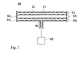
- Reference number 60 in Figure 7 represents the double pipe for degassing.
- This double pipe 60 has an inner pipe 61 and an outer pipe 62 placed around the inner pipe 61 to surround the periphery of the inner pipe 61.
- the inner pipe 61 is inserted into the outer pipe 62.
- the inner pipe 61 is made of a gas-permeable and liquid-impermeable resin (such as PTFA, etc.), and the outer pipe 62 is a pipe made of a gas-impermeable and liquid-impermeable metal (SUS).
- the inner and outer pipes 61, 62 are flexible and can be bent.
- Connecting members 69 1 , 69 2 for connecting to other lines are provided between the ends of the inner pipe 61 and the ends of the outer pipe 62, and the clearance 63 between the inner pipe 61 and outer pipe 62 is blocked by the connecting members 69 1 , 69 2 at both ends of the inner pipe 61 and therefore hermetically sealed.
- the outer pipe 62 has an exhaust port 64, which is connected to a vacuum pump 68 so that the clearance 63 can be evacuated.
- He gas is used as the pressurized gas described above and the low solubility of He gas reduces generating bubble.
- the number of the valves may be one or more than two as long as either one or both of the first and second circulation tanks 31L,31R can be connected to the main line 37.
- the number of return valves vr L , vr R is not limited to two, but any number of the valves may be used so far as either one or both of the first and second circulation tanks 31L,31R can be connected to the return line 38.
- the present invention can be applied to applicators discharging solutions such as pigment dispersion liquid inks for forming color filter, spacer dispersion liquids for forming spacers, solutions of which various functional solids (such as, conductive, dielectric, semiconductor, luminescent and electron-emitting materials, etc) . They can be used to coat the overall surfaces or discharge the solutions onto only predetermined positions to form patterns.
- solutions such as pigment dispersion liquid inks for forming color filter, spacer dispersion liquids for forming spacers, solutions of which various functional solids (such as, conductive, dielectric, semiconductor, luminescent and electron-emitting materials, etc) . They can be used to coat the overall surfaces or discharge the solutions onto only predetermined positions to form patterns.
- Applicators discharging spacers can also be used as spacer arrangement systems for placing a spacer between a color filter substrate and an array substrate of a liquid crystal display.
Landscapes
- Physics & Mathematics (AREA)
- Nonlinear Science (AREA)
- Engineering & Computer Science (AREA)
- Manufacturing & Machinery (AREA)
- Chemical & Material Sciences (AREA)
- Crystallography & Structural Chemistry (AREA)
- General Physics & Mathematics (AREA)
- Optics & Photonics (AREA)
- Coating Apparatus (AREA)
- Application Of Or Painting With Fluid Materials (AREA)
- Liquid Crystal (AREA)
Abstract
Description
- The present invention generally relates to inkjet spacer applicators, especially to circulating spacer applicators.
- Recently, inkjet spacer applicators of which inkjet printer is adapted have been used to apply spacers for liquid crystal display.
-
Reference 111 inFigure 9 (a) represents an example of a spacer applicator having anink head 121 retained in aholding frame 120 above aplatform 105, and a dispersion liquid of which spacers are dispersed is discharged from theink head 121 while theink head 121 andsubstrate 107 for a liquid crystal on theplatform 105 are relatively moved along ascanning direction 109, whereby the dispersion liquid lands at a desired position on the surface of thesubstrate 107 and the spacer is placed there. -
Figure 8 is a block diagram for illustrating a system for supplying the dispersion liquid of theconventional spacer applicator 111. - In this
spacer applicator 111, theink head 121 consists of a plurality ofhead modules 121a to 121c each connected to afeed tank 136 placed at a lateral position with respect to theplatform 105. - A
dispersion liquid 138 is stored in thefeed tank 136 to the same height as the positions of discharge holes of thehead modules 121a to 121c, and when valves between thefeed tank 136 and thehead modules 121a to 121c are opened to connect thefeed tank 136 and thehead modules 121a to 121c and gas is supplied into thefeed tank 136 by apressurizer 130, the pressure in thefeed tank 136 increases so that thedispersion liquid 138 in thefeed tank 136 is supplied to thehead modules 121a to 121c. - The
head modules 121a to 121c are connected to arecovery tank 137 so that the dispersion liquid supplied from thefeed tank 136 flow through thehead modules 121a-121c and then returns to therecovery tank 137. - The
recovery tank 137 and thefeed tank 136 are connected to each other, whereby thedispersion liquid 139 recovered in therecovery tank 137 can be returned to thefeed tank 136. - Patent document 1:
JPA 2004-50059 - Patent document 2:
JPA 2002-72218 - Patent document 3:
JPA HEI-11-7028 - In the
conventional applicator 111, gases are readily dissolved in thedispersion liquid 138 because the dispersion liquid is supplied to thehead modules 121a to 121c by pressurization as described above, and when the dissolved gas is reduced to bubbles in thehead modules 121a-121c, discharge failure may occur. - If the dispersion liquid is supplied by pumping, otherproblems, (such as, engulfing of gas and deformation or damage of the spacer) occur.
- In order to solve the problems described above, the present invention provides an applicator for allowing a dispersion liquid of which solid microparticles are dispersed to land at a desired position on a substrate by relatively moving a head module and the substrate, including a first and a second circulation tanks placed outside the head module; a buffer tank provided in the head module; a discharge chamber having an inlet connected to the buffer tank; a main line provided between the first and second circulation tanks and the buffer tank; a return line provided between an outlet of the discharge chamber and the first and second circulation tanks; a feed valve provided on the main line for connecting at least one of the first and second circulation tanks to the buffer tank; and a return valve provided on the return line for connecting at least one of the first and second circulation tanks to the head module. The first and second circulation tanks and the buffer tank are hermetically sealed and the pressure of the space above the dispersion liquid placed in each of the tanks can be controlled.
- The present invention also provides the applicator including a gas feed/evacuation system connected to the first and second circulation tanks, wherein the gas feed/evacuation system has a structure supplying a pressurized gas to, and evacuating from a space above the liquid level of the dispersion liquid in the first and second circulation tanks.
- The present invention also provides the applicator wherein a vacuum pump and a gas feeding system are connected to the buffer tank in order to control the pressure of the space above the liquid level of the dispersion liquid in the buffer tank.
- The present invention also provides the applicator wherein He is supplied from the gas feeding system.
- The present invention also provides the applicator including a transfer line provided between the first and second circulation tanks whereby the dispersion liquid can be transferred between the first and second circulation tanks without passing through the discharge chamber.
- The present invention also provides the applicator including a filter for separating clusters provided on the transfer line, which allows the individual solidmicroparticles to pass and catches clusters of the solid microparticles.
- The present invention also provides the applicator including a filter for removing solid microparticles provided on the transfer line, which catches the individual solid microparticles.
- The present invention also provides the applicator wherein at least a part of the lines through which the dispersion liquid is supplied from the circulation tanks to the discharge chamber consists of a double pipe having a liquid-impermeable and gas-permeable inner pipe through which the dispersion liquid passes and a gas-impermeable outer pipe of which the inner pipe is inserted into, and a clearance between the inner pipe and the outer pipe can be evacuated.
- The present invention also provides a method for transferring a dispersion liquid by transferring a circulating liquid in any one of the applicators described above, including when one of the first or second circulation tanks is served as a delivery source, making a pressure inside the circulation tank serving as the delivery source lower than the atmospheric pressure, and opening the feed valve to connect one of the first or second circulation tank serving as delivery source to the buffer tank in order to transfer the dispersion liquid from the circulation tank serving as delivery source to the buffer tank.
- The present invention also provides a method for transferring a dispersion liquid by transferring a circulating liquid in any one of the applicators described above, including when one of the first or second circulation tanks is served as a recovery destination, making a pressure inside the circulation tank serving as the recovery destination lower than the atmospheric pressure, and opening the return valve to connect either one of the first or second circulation tanks serving as recovery destination to the discharge chamber in order to transfer the dispersion liquid inside the discharge chamber to the circulation tank serving as recovery destination.
- The present invention also provides a method for transferring a dispersion liquid by transferring a circulating liquid in any one of the applicators described above, including opening the feed valve to connect either one of the first or second circulation tanks serving as delivery source to the buffer tank, opening the return valve to connect the other of the first or second circulation tanks serving as recovery destination to the discharge chamber, and transferring the dispersion liquid inside the circulation tank serving as the delivery source to the other circulation tank serving as the recovery destination through the buffer tank and the discharge chamber.
- The present invention is constructed as described above, in which the dispersion liquid is supplied from the circulation tank to the buffer tank when the circulation tank and the buffer tank are connected while the pressure in the space above the dispersion liquid in the buffer tank (the space in the buffer tank) is lower than the pressure in the space above the dispersion liquid in the circulation tank (the space in the circulation tank).
- When the circulation tank and the discharge chamber are connected to each other, while the force by which the circulation tank sucks the dispersion liquid in the discharge chamber is greater than the force by which the buffer tank aspirates the dispersion liquid in the discharge chamber, the dispersion liquid in the discharge chamber being aspirated into the circulation tank.
- Gas dissolution into the dispersion liquid and bubble generating are reduced because the dispersion liquid is not contacted with gases having pressures higher than the atmospheric pressure.
- No gas is engulfed into the dispersion liquid by pumping and generating gas can be prevented because no pump is used for transferring the dispersion liquid.
- Microparticles dispersed in the dispersion liquid are not deformed or damaged because no pump is used.
- No precipitation occurs because the dispersion liquid can be circulated.
-
-
Figure 1 is a diagram showing the circulation system of a applicator according to an example of the present invention. -
Figure 2 is a diagram for illustrating a route along which a dispersion liquid flows from a first circulation tank to a second circulation tank. -
Figure 3 is a diagram for illustrating a route along which dispersion liquid flows from the second circulation tank to the first circulation tank. -
Figure 4 is a diagram for illustrating a dispersion liquid flowing through a filter for separating clusters. -
Figure 5 is a diagram for illustrating a dispersion liquid flowing through a filter for removing solid microparticles. -
Figure 6 is a diagram for illustrating the applicator that returns dispersion liquid from discharge chambers directly to buffer tanks. -
Figure 7 is a diagram for illustrating a deaeration unit consisting of a double pipe. -
Figure 8 is a diagram for illustrating the circulation pathway of a dispersion liquid in a conventional applicator. -
Figure 9 (a) is a schematic illustration of the conventional applicator andFigure 9 (b) is a schematic illustration of an example of the applicator of the present invention. -
- 7:
- substrate;
- 11:
- applicator;
- 21:
- ink head;
- 24:
- gas feed/evacuation system
- 50:
- cylinder;
- 21a to 21c:
- head modules;
- 31L, 31R:
- circulation tank;
- 37:
- main line;
- 38:
- return line;
- 39:
- transfer line;
- 41a to 41c:
- buffer tanks;
- 42a to 42c:
- discharge chambers;
- 46:
- ultrasonic wave generator;
- 47:
- filter for separating clusters;
- 49:
- filter for removing solid microparticles;
- 57:
- gas feeding system;
- 58:
- vacuum pump;
- VSL, VSR:
- feed valves;
- vrL, vrR:
- return valves.
-
Reference 11 inFigure 9(b) represents an example of a applicator of the present invention including a platform 5 on which a substrate 7 is mounted. - A holding
frame 20 is provided above the platform 5. The holdingframe 20 has anink head 21. - As shown in
Figure 1 , theink head 21 includes a plurality ofhead modules head modules 21a to 21c,buffer tanks 41a to 41c anddischarge chambers 42a to 42c are provided, respectively. - The
applicator 11 has a circulation system supplying a dispersion liquid to thehead modules 21a to 21c.Reference 10 inFigure 1 represents the circulation system, and afirst circulation tank 31L and asecond circulation tank 31R are provided in thecirculation system 10. - The first and
second circulation tanks - The
buffer tanks 41a to 41c are placed above thedischarge chambers 42a to 42c, anddispersion liquid 48a to 48c of which solid microparticles are dispersed is stored in thebuffer tanks 41a to 41c. Thedispersion liquid 48a to 48c is contained in thebuffer tanks 41a to 41c to the extent that a space is formed above the liquid level of thedispersion liquid 48a to 48c in thebuffer tanks 41a to 41c. -
Avacuumpump 58 is connected to the ceilings or upper positions of the wall surfaces of each of thebuffer tanks 41a to 41c. The vacuum pump is connected to the eachbuffer tank 41a to 41c at positions above the liquid level of the dispersion liquid in thebuffer tanks 41a to 41c so that the pressure of the space above the liquid level of thedispersion liquid 48a to 48c in thebuffer tanks 41a to 41c can be decreased by evacuating the space. - A
gas feeding system 57 is also connected to the ceilings or upper positions of the wall surfaces of thebuffer tanks 41a to 41c. The gas feeding system is connected to thebuffer tanks 41a to 41c at positions above the liquid level of the dispersion liquid in thebuffer tanks 41a to 41c so that the pressure in the space above the liquid level of thedispersion liquid 48a to 48c in thebuffer tanks 41a to 41c can be increased by supplying this space with a pressurized gas less soluble for the dispersion liquid. - The
buffer tanks 41a to 41c have feed ports at positions below the liquid level of the dispersion liquid at, for example, bottom portions or lower parts of the wall surfaces thereof, and thedischarge chambers 42a to 42c have inlets on their wall surfaces or ceilings. - The feed ports of the
buffer tanks 41a to 41c are connected to the inlets of thedischarge chambers 42a to 42c, respectively, so that the dispersion liquid in thebuffer tanks 41a to 41c can be transferred to thedischarge chambers 42a to 42c. - The
discharge chambers 42a to 42c are located at such positions that their bottoms face the substrate mounted on the platform 5. Thedischarge chambers 42a to 42c have a number of discharge holes at their bottoms through which the dispersion liquid in thedischarge chambers 42a to 42c are in contact with the atmosphere. - When the pressure PB of the space in the
buffer tanks 41a to 41c is negative pressure (PB < (atmospheric pressure)) and the suction force of the negative pressure is balanced the weight of thedispersion liquid 48a to 48c in thebuffer tanks 41a to 41c, the dispersion liquid in thedischarge chambers 42a to 42c does not drop from the discharge holes; and therefore, thedispersion liquid 48a to 48c in thebuffer tanks 41a to 41c is not transferred to thedischarge chambers 42a to 42c. - Each
discharge chamber 42a-42c has cells corresponding to the discharge holes, and each cell has a piezoelectric element. - When a voltage is applied to the piezoelectric element, the piezoelectric element expands and contracts by the piezoelectric effect, whereby the dispersion liquid in each cell is pressurized and discharged from the discharge hole of the cell toward the surface of the substrate 7.
- When the dispersion liquid in the
discharge chamber 42a to 42c is discharged, the dispersion liquid is drawn from thebuffer tank 41a to 41c in order to supply to thedischarge chamber 42a to 42c with the amount of thedispersion liquid 48a to 48c discharged. - If the liquid level of the dispersion liquid in the
buffer tanks 41a to 41c drops, a pressurized gas is introduced into thebuffer tanks 41a to 41c from thegas feeding system 57 or the dispersion liquid is supplied from thefirst circulation tank 31L, or thesecond circulation tank 31R as described later so that the pressure of the space in thebuffer tanks 41a to 41c remains constant. - The transfer of the dispersion liquid from
circulation tanks buffer tanks 41a to 41c is performed by the weight of thedispersion liquid 23L in thefirst circulation tank 31L or thedispersion liquid 23R in thesecond circulation tank 31R and the force of difference between the pressure in the first orsecond circulation tank buffer tanks 41a to 41c. - The substrate 7 and the holding
frame 20 are arranged in such a manner that either one or both of them may move along a scanning direction 9. The substrate 7 may be stationary while the holdingframe 20 may move along the scanning direction 9, or the holdingframe 20 may be stationary while thesubstrate 20 may move along the scanning direction 9. The substrate 7 and the holdingframe 20 may move in the same direction or opposite directions along the scanning direction 9. In any case, theink head 21 moves with the holdingframe 20. - As a result, the substrate 7 can move relative to the
ink head 21, i.e., relative to thebuffer tanks 41a to 41c and thedischarge chambers 42a to 42c. - When the substrate 7 and the
ink head 21 are relatively moved until theink head 21 reaches a desired position on the substrate 7, and then a voltage is applied to the piezoelectric element to discharge the dispersion liquid from the discharge hole, the discharged dispersion liquid lands at the desired position on the surface of the substrate 7. - In the dispersion liquid, solid particles (such as, spacer or pigment) are dispersed. After the dispersion solvent included in the landed dispersion liquid is evaporated, the solid particles are fixed on the substrate 7.
- Besides the
circulation system 10, a dispersionliquid feeding system 28 is provided, and the first andsecond circulation tanks liquid feeding system 28. - Valves v1, v2 are provided on the midway of lines connecting the first and
second circulation tanks liquid feeding system 28. When the valves v1, v2 are opened, the dispersion liquid of which the solid microparticles are dispersed is supplied from the dispersionliquid feeding system 28 to the first andsecond circulation tanks -
Figure 1 and the other drawings described later show open valves in white and closed valves in black; and therefore,Figure 1 shows that the valve v1 connected to thefirst circulation tank 31L is at an open state as shown by white while the valve v2 connected to thesecond circulation tank 31R is at a closed state as shown by black. - A gas feed/
evacuation system 24 is connected to the first andsecond circulation tanks switches evacuation system 24 includes agas feeding system 44 and a vacuum pump (or evacuation system) 45 so that the first andsecond circulation tanks gas feeding system 44 and thevacuum pump 45 by switching valves in theswitches gas feeding system 44 and the other to thevacuum pump 45. - The first and
second circulation tanks evacuation system 24 at their ceilings or upper parts of the wall surfaces above the liquid level of thedispersion liquid second circulation tanks - The first and
second circulation tanks gas feeding system 44 via theswitches gas feeding system 44, the pressure of the space in the first andsecond circulation tanks - When the first and
second circulation tanks vacuum pump 45 via theswitches dispersion liquid vacuum pump 45, the pressure of the space above the liquid level decreases. - The first and
second circulation tanks dispersion liquid - Each
buffer tank 41a to 41c has an inlet, which is connected to the feed ports of the first andsecond circulation tanks main line 37. In the figure, the feed ports are the ends of the main lines. - A first feed valve and a second feed valve vsR are provided on the pathway of the
main line 37 near the feed ports of the first andsecond circulation tanks buffer tanks 41a to 41c than the first and second feed valves vsL, vsR. When either one of the first and second feed valves VSL VSR is opened while the other is closed and the inlet valve via-vic of thehead module 21a to 21c to be fed is opened, the first orsecond circulation tank buffer tank 41a to 41c connected to the opened inlet valve via-vic serves as delivery destination so that the delivery source and the delivery destination are connected. - The pressure Ps of the space in the
circulation tanks second circulation tank buffer tank 41a to 41c (PB<PS), thedispersion liquid second circulation tank buffer tank 41a to 41c serving as delivery destination via themain line 37. - Once a predetermined amount of the
dispersion liquid 48a to 48c has been stored in thebuffer tank 41a to 41c, thebuffer tank 41a to 41c is ready to supply the dispersion liquid to thedischarge chamber 42a to 42c. - Even if the pressurized gas is supplied to the first or
second circulation tanks - When the
discharge chamber 42a to 42c is filled with the dispersion liquid, it is possible to discharge the dispersion liquid onto the surface of the substrate 7. - Next, downstream side from the
discharge chambers 42a to 42c will be explained. - Each
discharge chamber 42a to 42c has an outlet, and each of first andsecond circulation tanks return line 38 is provided between the outlet of the discharge chamber 42 and the inlets of the first andsecond circulation tanks return line 38. - The
return line 38 has outlet valves voa-voc near the outlets of thedischarge chambers 42a to 42c, respectively, and a first return valve vrL and a second return valve vrR positioned nearer to the outlets of the first andsecond circulation tanks - The return valves vrL, vrR are valves for connecting at least one of the first and second circulation tanks to the head modules. When either one of the first and second feed valves vsL, vsR is opened and the other is closed, the first or
second circulation tank second circulation tank discharge chamber discharge chamber second circulation tank discharge chamber 42a to 42c serves as return source. - In this situation, if the dispersion liquid in each
discharge chamber 42a to 42c is in contact with the atmosphere in the discharge holes, the dispersion liquid in thedischarge chamber 42a to 42c serving as return source can be transferred to the first orsecond circulation tank second circulation tank - The dispersion liquid can be made to flow from the inlet to the outlet in the
discharge chamber 42a to 42c and then, the dispersion liquid can be transferred to thecirculation tank second circulation tank buffer tank 41a to 41c and decreasing the pressure at the outlet of thedischarge chamber 42a to 42c lower than the pressure at the inlet of thedischarge chamber 42a to 42c. - The outlet valves voa-voc are three-way valves, so that the outlet valves voa-voc can connect not only the
discharge chamber 42a to 42c to the first orsecond circulation tank discharge chamber 42a to 42c to drains. - The
applicator 11 of the present invention has a level sensor detecting the height of the liquid level of thedispersion liquid 48a to 48c in thebuffer tanks 41a to 41c and a pressure sensor measuring the pressure in the space above the liquid level of thedispersion liquid 48a to 48c in the buffer tanks. Any change in the liquid level in thebuffer tanks 41a to 41c or any change of the pressure in the space above the liquid level is detected so that the dispersion liquid is added from the first orsecond circulation tank gas system 57, or thebuffer tank 41a to 41c is evacuated by thevacuum pump 58 in order to maintain a constant pressure, whereby thedispersion liquid 48a to 48c in thebuffer tanks 41a to 41c is prevented from dropping from the discharge holes of thedischarge chambers 42a to 42c. - When a part or all of the dispersion liquid in the
discharge chambers 42a to 42c is transferred to the first orsecond circulation tank buffer tanks 41a to 41c is transferred to thedischarge chambers 42a to 42c. In this case, the liquid level of thedispersion liquid 48a to 48c in thebuffer tanks 41a to 41c is lowered and the pressure in the space in thebuffer tanks 41a to 41c decrease. - In this case, since the dispersion liquid in the first or
second circulation tank buffer tanks 41a to 41c, then the dispersion liquid can be transferred from the first orsecond circulation tank second circulation tank buffer tanks 41a to 41c anddischarge chamber 42a to 42c. - During this operation, the pressure of the inner space in the
buffer tanks 41a to 41e can be maintained at a predetermined value. -
Figure 2 shows the state in which the dispersion liquid flows from thefirst circulation tank 31L serving as delivery source to thesecond circulation tank 31R serving as recovery destination (i.e., the first feed valve vsL and the second return valve vrR are opened and the second feed valve vsR and the first return valve vrL are closed). The dispersion liquid flows from thefirst circulation tank 31L to the second circulation tank 32R. -
Figure 2 andFigures 3 to 5 , described later, are diagrams for illustrating the flow of the dispersion liquid, in which the lines through which the dispersion liquid flow are shown by solid lines while the other lines are shown by dashed lines. - In contrast to
Figure 2 ,Figure 3 shows the state in which the dispersion liquid flows from thesecond circulation tank 31R serving as delivery source to thefirst circulation tank 31L serving as recovery destination when the first feed valve and the second return valve vrR are closed and the second feed valve vsR and the first return valve vrL are opened. - Next, the pathway along which the dispersion liquid is directly transferred between the first and
second circulation tanks - The first and
second circulation tanks dispersion liquid second circulation tanks - Since the first and second transfer ports are connected to each other by a
transfer line 39, which is distinct from themain line 37 and thereturn line 38, the inside of the first and second circulation tanks are connected by thetransfer line 39. In this example, the first and second transfer ports consist of the end of thetransfer line 39. - The valves provided on the
main line 37 or returnline 38 are closed to cut off the connection between the first andsecond circulation tanks buffer tanks 41a to 41c via themain line 37 or the connection between the first andsecond circulation tanks discharge chambers 42a to 42c via thereturn line 38. - Open-
close valves 26 are provided on thetransfer line 39, and the open-close valves 26 are closed to provide a pressure difference between the inside of thefirst circulation tank 31L and the inside of thesecond circulation tank 31R by the gas feed/evacuation system 24. The first orsecond circulation tank second circulation tank close valves 26 are opened, whereby the dispersion liquid flows from the first orsecond circulation tank second circulation tank - A
filter system 25 is provided on the halfway of thetransfer line 39. Thefilter system 25 includes a filter for separatingclusters 47 and a filter for removingsolid microparticles 49. The filter for separatingclusters 47 and the filter for removingsolid microparticles 49 are in parallel between the first andsecond circulation tanks second circulation tanks - Solid microparticles dispersed in the dispersion liquid may gather to form clusters having large particle sizes during circulation in lines or storage in tanks (such as, the
circulation tanks clusters 47 and removed when the dispersion liquid passes through the filter for separatingclusters 47 because the filter for separatingclusters 47 has a mesh size larger than the solid microparticles but smaller than the clusters of the solid microparticles. - The filter for separating
clusters 47 is also connected to anultrasonic wave generator 46 that applies ultrasonic waves to the filter for separatingclusters 47. - When ultrasonic waves are applied to the filter for separating
clusters 47, the clusters caught on the filter for separatingclusters 47 separate into individual solid microparticles and pass through the filter for separatingclusters 47, whereby the dispersion liquid is regenerated during circulation in thetransfer line 39 because the clusters are decomposed. -
Figure 4 shows the state in which the dispersion liquid flows through the filter for separatingclusters 47 in thetransfer line 39 from thesecond circulation tank 31R toward thefirst circulation tank 31L. The dispersion liquid recovered by the first orsecond circulation tank second circulation tank - The dispersion liquid flowing through the
transfer line 39 can also pass through the filter for removingsolid microparticles 49 in parallel to the filter for separatingclusters 47 instead of passing through the filter for separatingclusters 47 by manipulating the open-close valves 26 on thetransfer line 39. -
Figure 5 shows the state in which the dispersion liquid flows through the filter for removingsolid microparticles 49 in thetransfer line 39 from thesecond circulation tank 31R toward thefirst circulation tank 31L. - Solid microparticles contained in the dispersion liquid cannot pass through the filter for removing
solid microparticles 49 because the filter for removingsolid microparticles 49 has a mesh size smaller than the microparticles. Thus, the solid microparticles are totally caught on the filter for removingsolid microparticles 49 when the dispersion liquid passes through the filter for removingsolid microparticles 49. - The
applicator 11 should be adaptable to multiple types of dispersion liquids, such as, dispersion liquids of which microparticles of different materials are dispersed or dispersion liquids of which microparticles of different particle sizes are dispersed. - The procedure for changing the dispersion liquid using the filter for removing
solid microparticles 49 is explained as follows. In order to change the dispersion liquid circulated in theapplicator 11 and discharged from theink head 21, it is necessary to first remove the dispersion liquid in thelines 37 to 39 and the dispersion liquid in thetanks tanks liquid feeding system 28 to the first andsecond circulation tanks - In this
applicator 11, thesolvent feeding system 29 is connected to either one or both of the first andsecond circulation tanks first circulation tank 31L, and the valve between thesolvent feeding system 29 and thefirst circulation tank 31L is opened to supply a washing liquid to thefirst circulation tank 31L from thesolvent feeding system 29 after the dispersion liquid in the eachtanks head modules 21a to 21c and lines 37-39 has been discharged into drains and before another dispersion liquid is placed in the first andsecond circulation tanks second circulation tank 31R via thebuffer tanks 41a to 41c andhead modules 21a to 21c, and the washing liquid is returned from thesecond circulation tank 31R to thefirst circulation tank 31L via thetransfer line 39. - Thus, the inside of the
tanks lines 37 to 39 are washed and microparticles are removed by supplying a washing liquid (solvent) to either one of the first orsecond circulation tank - After the washing liquid has been discharged from drains, a fresh dispersion liquid is placed in the first and
second circulation tanks - Before the dispersion liquid is discharged into drains and replaced with a washing liquid, microparticles in the dispersion liquid to be replaced are removed by the
filter 49 for removing solid microparticles, and the dispersion liquid solvent is circulated, whereby the inside of the lines is first washed with the dispersion liquid solvent of the dispersion liquid. Then, the dispersion liquid solvent is discharged followed by washing with a washing liquid, whereby the washing liquid can be saved. - In this example, a
bypass line 40 connecting the first andsecond circulation tanks filter system 25 is provided in parallel to thetransfer line 39 of which thefilter system 25 is provided midway its line. - The
bypass line 40 has an open-close valve 27. When the open-close valve 27 is closed, the dispersion liquid does not flow through thebypass line 40, and when the open-close valve 27 on thebypass line 40 is opened while the open-close valves 26 on thetransfer line 39 are closed, the dispersion liquid flows through thebypass line 40 under a pressure difference in the space in the first andsecond circulation tanks circular tanks bypass line 40, is arranged below the liquid level of the first andsecond circulation tanks - A washer 6 is provided at a lateral position with respect to the platform 5, and a washing liquid or dispersion liquid solvent can also be circulated while the discharge holes are blocked with the washer 6 by moving the
ink head 21 from a position above the substrate 7 to a position above the washer 6. - A
gas feeding system 57 is connected to thebuffer tanks 41a to 41c via valves. When theink head 21 is moved from a position above the substrate 7 to the washer 6 and then the outlet valves voa to voc on thereturn line 38 are closed, and valves provided between thegas feeding system 57 and thebuffer tanks 41a to 41c are opened and purge gas is introduced intobuffer tanks 41a to 41c while the discharge holes are opened, the pressure inside thebuffer tanks 41a to 41c are introduced at atmospheric pressure or higher than atmospheric pressure. Consequently, the dispersion liquid or washing liquid in thebuffer tanks 41a to 41c can be discharged from the discharge holes of thehead modules 21a to 21c into the washer 6. - As explained above, in the
applicator 11 of the present invention, when one of the first andsecond circulation tanks second circulation tank second circulation tanks second circulation tanks buffer tanks 41a to 41c and thedischarge chamber 42a to 42c. Consequently, it is possible to prevent sinking of solid microparticles in thedischarge chamber 42a to 42c or inside of lines. - If the dispersion liquid in the first or
second circulation tank second circulation tank buffer tanks 41a to 41c to thedischarge chambers 42a to 42c and the dispersion liquid can be returned to the first orsecond circulation tank clusters 47. - The first and
second circulation tanks ultrasonic wave oscillators ultrasonic wave generators ultrasonic wave oscillator second circulation tanks - The first and
second circulation tanks rotors second circulation tanks stirrers rotors stirrers rotors second circulation tanks - The part of each line 37-40 described above, especially of the
main line 37 where the dispersion liquid is supplied from the first andsecond circulation tanks discharge chambers 42a to 42c can totally or partially consist of a double pipe in order to degas the dispersion liquid flowing through the double pipe. The double pipe is desirably placed immediately before the position where the dispersion liquid is discharged, i.e., between thebuffer chambers 41a to 41c and thedischarge chambers 42a to 42c. -
Reference number 60 inFigure 7 represents the double pipe for degassing. Thisdouble pipe 60 has aninner pipe 61 and anouter pipe 62 placed around theinner pipe 61 to surround the periphery of theinner pipe 61. Theinner pipe 61 is inserted into theouter pipe 62. - The
inner pipe 61 is made of a gas-permeable and liquid-impermeable resin (such as PTFA, etc.), and theouter pipe 62 is a pipe made of a gas-impermeable and liquid-impermeable metal (SUS). The inner andouter pipes - Connecting members 691, 692 for connecting to other lines are provided between the ends of the
inner pipe 61 and the ends of theouter pipe 62, and theclearance 63 between theinner pipe 61 andouter pipe 62 is blocked by the connecting members 691, 692 at both ends of theinner pipe 61 and therefore hermetically sealed. - The
outer pipe 62 has anexhaust port 64, which is connected to avacuum pump 68 so that theclearance 63 can be evacuated. - When the
clearance 63 is evacuated during circulation of the dispersion liquid from one to the other of both ends 661, 662 of theinner pipe 61, the gases dissolved in the dispersion liquid are sucked into theclearance 63 through theinner pipe 61 so that gasses are removed from the dispersion liquid. - He gas is used as the pressurized gas described above and the low solubility of He gas reduces generating bubble.
- Although two feed valves vsL, vsR are provided in the foregoing description, the number of the valves may be one or more than two as long as either one or both of the first and
second circulation tanks main line 37. - Similarly, the number of return valves vrL, vrR is not limited to two, but any number of the valves may be used so far as either one or both of the first and
second circulation tanks return line 38. - As shown in
Figure 6 , when pumps which do not engulf gas are connected between thereturn line 38 at the downstream from thedischarge chamber 42a to 42c andmain line 37 positioned between thebuffer tanks 42a to 42c and the first orsecond circulation tanks discharge chamber 42a to 42c and drained from thedischarge chamber 42a to 42c is returned from thereturn line 38 to themain line 37, the dispersion liquid discharged from thedischarge chamber 41a to 42c can be returned to thebuffer tanks 41a to 42c. - The present invention can be applied to applicators discharging solutions such as pigment dispersion liquid inks for forming color filter, spacer dispersion liquids for forming spacers, solutions of which various functional solids (such as, conductive, dielectric, semiconductor, luminescent and electron-emitting materials, etc) . They can be used to coat the overall surfaces or discharge the solutions onto only predetermined positions to form patterns.
- Applicators discharging spacers can also be used as spacer arrangement systems for placing a spacer between a color filter substrate and an array substrate of a liquid crystal display.
Claims (11)
- An applicator for allowing dispersion liquid of which solid microparticles are dispersed to be applied at a desired position on a substrate by relatively moving a head module and the substrate, comprising:a first and a second circulation tanks placed outside the head module;a buffer tank provided in the head module;a discharge chamber having an inlet connected to the buffer tank;a main line provided between the first and second circulation tanks and the buffer tank;a return line provided between an outlet of the discharge chamber and the first and second circulation tanks;a feed valve provided on the main line for connecting at least one of the first and second circulation tanks to the buffer tank; anda return valve provided on the return line for connecting at least one of the first and second circulation tanks to the head module,wherein the first and second circulation tanks and the buffer tank are hermetically sealed and the pressure of the space above the dispersion liquid placed in each of the tanks can be controlled.
- The applicator according to claim 1, further comprising a gas feed/evacuation system connected to the first and second circulation tanks,
wherein the gas feed/evacuation system has a structure supplying a pressurized gas to and evacuating from a space above the liquid level of the dispersion liquid in the first and second circulation tanks. - The applicator according to claim 1, further comprising a vacuum pump and a gas feeding system connected to the buffer tank in order to control the pressure of a space above the liquid level of the dispersion liquid in the buffer tank.
- The applicator according to claim 3, wherein He is supplied from the gas feeding system.
- The applicator according to claim 1, further comprising a transfer line provided between the first and second circulation tanks whereby the dispersion liquid can be transferred between the first and second circulation tanks without passing through the discharge chamber.
- The applicator according to claim 5, further comprising a filter for separating clusters provided on the transfer line, which allows the individual solidmicroparticles to pass and catches clusters of the solid microparticles.
- The applicator according to claim 5, further comprising a filter for removing solid microparticles on the transfer line, which catches the individual solid microparticles.
- The applicator of claim 1, wherein at least a part of the lines through which the dispersion liquid is supplied from the circulation tanks to the discharge chamber comprises a double pipe having a liquid-impermeable and gas-permeable inner pipe through which the dispersion liquid passes, and a gas-impermeable outer pipe of which the inner pipe is inserted into, and a clearance between the inner pipe and the outer pipe can be evacuated.
- A method for transferring a dispersion liquid for transferring a circulating liquid in the applicator according to claim 1, comprising, when one of the first or second circulation tanks is served as a delivery source, the steps of:making a pressure inside the circulation tank serving as the delivery source lower than the atmospheric pressure; andopening the feed valve to connect one of the first or second circulation tank serving as delivery source to the buffer tank in order to transfer the dispersion liquid from the circulation tank serving as delivery source to the buffer tank.
- A method for transferring a dispersion liquid for transferring a circulating liquid in the applicator according to claim 1, comprising, when one of the first or second circulation tanks is served as a recovery destination, the steps of:making a pressure inside the circulation tank serving as the recovery destination lower than the atmospheric pressure; andopening the return valve to connect either one of the first or second circulation tanks serving as recovery destination to the discharge chamber in order to transfer the dispersion liquid inside the discharge chamber to the circulation tank serving as recovery destination.
- A method for transferring a dispersion liquid for transferring a circulating liquid in the applicator according to claim 1, comprising the steps of:opening the feed valve to connect either one of the first or second circulation tanks serving as delivery source to the buffer tank;opening the return valve to connect the other of the first or second circulation tanks serving as recovery destination to the discharge chamber; andtransferring the dispersion liquid inside the circulation tank serving as the delivery source to the other circulation tank serving as the recovery destination through the buffer tank and the discharge chamber.
Applications Claiming Priority (2)
| Application Number | Priority Date | Filing Date | Title |
|---|---|---|---|
| JP2005325990 | 2005-11-10 | ||
| PCT/JP2006/321329 WO2007055102A1 (en) | 2005-11-10 | 2006-10-26 | Applicator and method of moving dispersion liquid |
Publications (3)
| Publication Number | Publication Date |
|---|---|
| EP1946849A1 true EP1946849A1 (en) | 2008-07-23 |
| EP1946849A4 EP1946849A4 (en) | 2013-05-29 |
| EP1946849B1 EP1946849B1 (en) | 2014-03-05 |
Family
ID=38023108
Family Applications (1)
| Application Number | Title | Priority Date | Filing Date |
|---|---|---|---|
| EP20060822305 Ceased EP1946849B1 (en) | 2005-11-10 | 2006-10-26 | Applicator and method of moving dispersion liquid |
Country Status (7)
| Country | Link |
|---|---|
| US (1) | US8171876B2 (en) |
| EP (1) | EP1946849B1 (en) |
| JP (1) | JP4647665B2 (en) |
| KR (1) | KR101003702B1 (en) |
| CN (1) | CN101267894B (en) |
| TW (1) | TWI398304B (en) |
| WO (1) | WO2007055102A1 (en) |
Cited By (5)
| Publication number | Priority date | Publication date | Assignee | Title |
|---|---|---|---|---|
| EP2511098A1 (en) * | 2011-04-14 | 2012-10-17 | Dip Tech. Ltd. | Ink tank system |
| ITUD20130154A1 (en) * | 2013-11-20 | 2015-05-21 | Neolt S P A In Concordato Preventi Vo | PRESS SYSTEM AND ITS PROCEDURE |
| WO2017000997A1 (en) * | 2015-06-30 | 2017-01-05 | Hewlett-Packard Development Company L.P. | Printing fluid circulation |
| WO2017178457A1 (en) * | 2016-04-14 | 2017-10-19 | OCE Holding B.V. | Ink jet printer |
| EP3461643A1 (en) * | 2017-09-29 | 2019-04-03 | Canon Kabushiki Kaisha | Liquid ejection apparatus and liquid ejection head |
Families Citing this family (22)
| Publication number | Priority date | Publication date | Assignee | Title |
|---|---|---|---|---|
| JP2007136417A (en) * | 2005-11-22 | 2007-06-07 | Ulvac Japan Ltd | Coating apparatus |
| JP4710673B2 (en) * | 2006-03-17 | 2011-06-29 | リコープリンティングシステムズ株式会社 | Droplet discharge device |
| JP4828287B2 (en) * | 2006-04-10 | 2011-11-30 | リコープリンティングシステムズ株式会社 | Droplet discharge device and operation method thereof |
| US9138771B2 (en) | 2008-05-19 | 2015-09-22 | E I Du Pont De Nemours And Company | Apparatus and method for solution coating thin layers |
| FR2955801B1 (en) | 2010-02-01 | 2012-04-13 | Markem Imaje | DEVICE FORMING A CONTINUOUS INK JET PRINTER WITH SOLVENT VAPOR CONCENTRATIONS INSIDE AND AROUND THE DECREASED PUPITRE |
| JP5488052B2 (en) | 2010-03-01 | 2014-05-14 | セイコーエプソン株式会社 | Liquid ejector |
| JP2012227413A (en) * | 2011-04-21 | 2012-11-15 | Mitsubishi Electric Corp | Sealing resin applying device and method for manufacturing light emitting device |
| JP5671414B2 (en) * | 2011-06-24 | 2015-02-18 | 株式会社日立製作所 | Liquid crystal material coating apparatus and liquid crystal material coating method |
| JP5741549B2 (en) | 2012-10-09 | 2015-07-01 | 東京エレクトロン株式会社 | Treatment liquid supply method, treatment liquid supply apparatus, and storage medium |
| DE102013103964A1 (en) * | 2013-04-19 | 2014-10-23 | Océ Printing Systems GmbH & Co. KG | Arrangement for recycling and returning carrier liquid in a printer or copier and associated method |
| KR101629789B1 (en) * | 2015-02-12 | 2016-06-14 | (주)신성이엔지 | Solvent Recovery Systems |
| JP6721956B2 (en) * | 2015-07-28 | 2020-07-15 | 株式会社Screenホールディングス | Coating device and coating method |
| US9707765B2 (en) * | 2015-11-23 | 2017-07-18 | Xerox Corporation | Inhibiting sediment formation in a MICR ink tank |
| JP6941365B2 (en) * | 2017-12-19 | 2021-09-29 | 武蔵エンジニアリング株式会社 | Droplet ejection device and droplet ejection method |
| EP3877095B1 (en) * | 2018-11-09 | 2025-02-26 | Illinois Tool Works Inc. | Modular fluid application device for varying fluid coat weight |
| JP7326051B2 (en) * | 2019-07-10 | 2023-08-15 | 株式会社日立産機システム | INKJET RECORDING DEVICE AND METHOD OF CONTROLLING INKJET RECORDING DEVICE |
| JP7321052B2 (en) * | 2019-10-17 | 2023-08-04 | 東京エレクトロン株式会社 | SUBSTRATE PROCESSING APPARATUS AND APPARATUS CLEANING METHOD |
| CN110733254B (en) * | 2019-12-20 | 2020-03-31 | 广东希望高科数字技术有限公司 | Ink path system of scanning type printing machine |
| JP6893276B1 (en) * | 2020-02-21 | 2021-06-23 | 花王株式会社 | Powder / granular material spraying device and powder / granular material spraying method |
| DE102021119858A1 (en) * | 2021-07-30 | 2023-02-02 | Koenig & Bauer Ag | Method for changing at least one printing fluid and method for cleaning and/or maintaining a printing fluid supply system and printing machine |
| IT202300014844A1 (en) * | 2023-07-14 | 2025-01-14 | Cefla Soc Cooperativa | INK RECIRCULATION SYSTEM, OR SIMILAR FOR PRINTING APPARATUS, IN PARTICULAR INKJET AND APPARATUS COMPRISING SAID RECIRCULATION SYSTEM |
| CN118624344B (en) * | 2024-08-14 | 2025-02-11 | 中国科学院地质与地球物理研究所 | A system for configuring standard gas and a method for configuring standard gas |
Family Cites Families (17)
| Publication number | Priority date | Publication date | Assignee | Title |
|---|---|---|---|---|
| JPH084773B2 (en) * | 1986-11-10 | 1996-01-24 | ノードソン株式会社 | Dispersion type liquid ejection method and apparatus |
| JPS6417028A (en) | 1987-07-10 | 1989-01-20 | Canon Kk | Liquid crystal phase grating |
| SE465756B (en) * | 1990-03-02 | 1991-10-28 | Qenico Ab | DEVICE FOR APPLICABLE APPLICATION OF PUMP PASTA, LIM, E D, ON A SUBSTRATE |
| ES2110170T3 (en) * | 1993-11-30 | 1998-02-01 | Danieli Off Mecc | A SYSTEM TO RE-CIRCULATE TREATMENT MATERIAL IN SURFACE TREATMENT AND FINISHING PROCESSES. |
| JPH08215626A (en) * | 1995-02-15 | 1996-08-27 | Mitsubishi Chem Corp | Coating method and coating device |
| JPH0975827A (en) * | 1995-09-08 | 1997-03-25 | Basf Corp | Recirculation device and method for automatic metering and feeding device |
| JPH11319685A (en) * | 1998-05-18 | 1999-11-24 | Futaba Corp | Liquid supply device |
| JP2002072218A (en) | 2000-08-24 | 2002-03-12 | Lac:Kk | Spacer spraying method and apparatus |
| JP4026768B2 (en) * | 2001-06-08 | 2007-12-26 | 日本たばこ産業株式会社 | Fluid coating apparatus and coating nozzle therefor |
| JP2003030000A (en) | 2001-07-17 | 2003-01-31 | Mitsubishi Electric Corp | Test pattern generation circuit and generation method for self-diagnosis circuit |
| JP2003275659A (en) * | 2002-01-17 | 2003-09-30 | Shibaura Mechatronics Corp | Coating device and method for removing air bubbles from coating device |
| JP4108353B2 (en) | 2002-03-29 | 2008-06-25 | ノードソン コーポレーション | Liquid ejection method and apparatus |
| JP4133063B2 (en) | 2002-07-19 | 2008-08-13 | 芝浦メカトロニクス株式会社 | Solution coating apparatus and supply method |
| JP4254437B2 (en) * | 2002-10-15 | 2009-04-15 | セイコーエプソン株式会社 | Liquid filling method, liquid filling device, and discharge device |
| JP3919112B2 (en) * | 2004-02-27 | 2007-05-23 | 東芝テック株式会社 | Inkjet recording device |
| TWI362059B (en) * | 2004-11-25 | 2012-04-11 | Az Electronic Mat Ip Japan Kk | Photoresist coating solution supply system and method for supplying photoresist coating solution using thereof, and photoresist coating system using thereof |
| EP1864722B1 (en) * | 2005-08-15 | 2011-10-26 | Canon Kabushiki Kaisha | Liquid applying apparatus and ink-jet printing apparatus |
-
2006
- 2006-10-26 JP JP2007544088A patent/JP4647665B2/en not_active Expired - Fee Related
- 2006-10-26 WO PCT/JP2006/321329 patent/WO2007055102A1/en not_active Ceased
- 2006-10-26 EP EP20060822305 patent/EP1946849B1/en not_active Ceased
- 2006-10-26 KR KR1020087006530A patent/KR101003702B1/en not_active Expired - Fee Related
- 2006-10-26 CN CN2006800343700A patent/CN101267894B/en active Active
- 2006-11-03 TW TW95140802A patent/TWI398304B/en not_active IP Right Cessation
-
2008
- 2008-04-28 US US12/149,133 patent/US8171876B2/en not_active Expired - Fee Related
Non-Patent Citations (2)
| Title |
|---|
| No further relevant documents disclosed * |
| See also references of WO2007055102A1 * |
Cited By (11)
| Publication number | Priority date | Publication date | Assignee | Title |
|---|---|---|---|---|
| EP2511098A1 (en) * | 2011-04-14 | 2012-10-17 | Dip Tech. Ltd. | Ink tank system |
| ITUD20130154A1 (en) * | 2013-11-20 | 2015-05-21 | Neolt S P A In Concordato Preventi Vo | PRESS SYSTEM AND ITS PROCEDURE |
| EP2875956A1 (en) * | 2013-11-20 | 2015-05-27 | Jet-Set Srl | Printing apparatus and corresponding method |
| WO2017000997A1 (en) * | 2015-06-30 | 2017-01-05 | Hewlett-Packard Development Company L.P. | Printing fluid circulation |
| CN107614270A (en) * | 2015-06-30 | 2018-01-19 | 惠普发展公司,有限责任合伙企业 | Printing-fluid circulates |
| US10315431B2 (en) | 2015-06-30 | 2019-06-11 | Hewlett-Packard Development Company, L.P. | Printing fluid circulation |
| WO2017178457A1 (en) * | 2016-04-14 | 2017-10-19 | OCE Holding B.V. | Ink jet printer |
| US10562317B2 (en) | 2016-04-14 | 2020-02-18 | Océ Holding B.V. | Method of printing |
| EP3461643A1 (en) * | 2017-09-29 | 2019-04-03 | Canon Kabushiki Kaisha | Liquid ejection apparatus and liquid ejection head |
| US20190100024A1 (en) | 2017-09-29 | 2019-04-04 | Canon Kabushiki Kaisha | Liquid ejection apparatus and liquid ejection head |
| US10792930B2 (en) | 2017-09-29 | 2020-10-06 | Canon Kabushiki Kaisha | Liquid ejection apparatus and liquid ejection head |
Also Published As
| Publication number | Publication date |
|---|---|
| WO2007055102A1 (en) | 2007-05-18 |
| KR20080066661A (en) | 2008-07-16 |
| JP4647665B2 (en) | 2011-03-09 |
| JPWO2007055102A1 (en) | 2009-04-30 |
| CN101267894B (en) | 2010-11-03 |
| EP1946849B1 (en) | 2014-03-05 |
| TWI398304B (en) | 2013-06-11 |
| KR101003702B1 (en) | 2010-12-27 |
| TW200722185A (en) | 2007-06-16 |
| US20080210160A1 (en) | 2008-09-04 |
| US8171876B2 (en) | 2012-05-08 |
| CN101267894A (en) | 2008-09-17 |
| EP1946849A4 (en) | 2013-05-29 |
Similar Documents
| Publication | Publication Date | Title |
|---|---|---|
| EP1946849B1 (en) | Applicator and method of moving dispersion liquid | |
| JP4188080B2 (en) | Closed ink delivery system and method with printhead ink pressure control | |
| KR100976176B1 (en) | Functional liquid supply device, droplet ejection device, manufacturing method of electro-optical device, electro-optical device and electronic device | |
| CN103285737B (en) | Backwash | |
| JP2008246337A (en) | Functional liquid supply device, droplet discharge device, electro-optical device manufacturing method, electro-optical device, and electronic apparatus | |
| TWI592201B (en) | Degassing device, coating device and degassing method | |
| CN110911307B (en) | Processing apparatus, processing system, and processing method | |
| MX2013014522A (en) | Ink- jet printing device. | |
| JPH08337296A (en) | Chemical supply device | |
| JP2010143071A (en) | Ink filling method | |
| CN112277314B (en) | Ink supply system and 3D printer | |
| JP2006192411A (en) | Functional liquid droplet ejection head initial filling method, functional liquid droplet ejection head initial filling device, functional liquid droplet ejection head, functional liquid supply device, liquid droplet ejection device, electro-optical device manufacturing method, electro-optical device, and electronic apparatus | |
| CN105946354B (en) | A kind of orientation liquid supply system | |
| JP2008238127A (en) | Bubble removing device, droplet discharge device, electro-optical device manufacturing method, electro-optical device, and electronic apparatus | |
| CN216902814U (en) | Semiconductor processing equipment | |
| JP5150391B2 (en) | Printing device | |
| JP2008238126A (en) | Bubble removing device, droplet discharge device, electro-optical device manufacturing method, electro-optical device, and electronic apparatus | |
| JP2005169235A (en) | Droplet discharge device | |
| KR102889257B1 (en) | Processing liquid providing apparatus and substrate treating system including the same | |
| JP2003094687A (en) | Liquid filling method and liquid filling device | |
| EP1013440B1 (en) | Fluid flush system for ink jet printing system | |
| US20260022693A1 (en) | Pump, chemical supply unit, and substrate treatment apparatus | |
| US11964493B2 (en) | Liquid ejecting apparatus and control method of liquid ejecting apparatus | |
| JPH115002A (en) | Degassing device | |
| US20250206025A1 (en) | Liquid ejecting apparatus, forming apparatus, control method, and article manufacturing method |
Legal Events
| Date | Code | Title | Description |
|---|---|---|---|
| PUAI | Public reference made under article 153(3) epc to a published international application that has entered the european phase |
Free format text: ORIGINAL CODE: 0009012 |
|
| 17P | Request for examination filed |
Effective date: 20080429 |
|
| AK | Designated contracting states |
Kind code of ref document: A1 Designated state(s): DE GB |
|
| DAX | Request for extension of the european patent (deleted) | ||
| RBV | Designated contracting states (corrected) |
Designated state(s): DE GB |
|
| A4 | Supplementary search report drawn up and despatched |
Effective date: 20130426 |
|
| RIC1 | Information provided on ipc code assigned before grant |
Ipc: B05D 3/00 20060101ALI20130422BHEP Ipc: B05C 11/10 20060101AFI20130422BHEP Ipc: B41J 2/18 20060101ALI20130422BHEP Ipc: B05C 5/00 20060101ALI20130422BHEP Ipc: G02F 1/13 20060101ALI20130422BHEP Ipc: B41J 2/175 20060101ALI20130422BHEP Ipc: B05D 1/26 20060101ALI20130422BHEP Ipc: G02F 1/1339 20060101ALI20130422BHEP |
|
| GRAP | Despatch of communication of intention to grant a patent |
Free format text: ORIGINAL CODE: EPIDOSNIGR1 |
|
| INTG | Intention to grant announced |
Effective date: 20131105 |
|
| GRAS | Grant fee paid |
Free format text: ORIGINAL CODE: EPIDOSNIGR3 |
|
| GRAA | (expected) grant |
Free format text: ORIGINAL CODE: 0009210 |
|
| AK | Designated contracting states |
Kind code of ref document: B1 Designated state(s): DE GB |
|
| REG | Reference to a national code |
Ref country code: GB Ref legal event code: FG4D |
|
| REG | Reference to a national code |
Ref country code: DE Ref legal event code: R096 Ref document number: 602006040553 Country of ref document: DE Effective date: 20140417 |
|
| REG | Reference to a national code |
Ref country code: DE Ref legal event code: R097 Ref document number: 602006040553 Country of ref document: DE |
|
| PLBE | No opposition filed within time limit |
Free format text: ORIGINAL CODE: 0009261 |
|
| STAA | Information on the status of an ep patent application or granted ep patent |
Free format text: STATUS: NO OPPOSITION FILED WITHIN TIME LIMIT |
|
| 26N | No opposition filed |
Effective date: 20141208 |
|
| REG | Reference to a national code |
Ref country code: DE Ref legal event code: R097 Ref document number: 602006040553 Country of ref document: DE Effective date: 20141208 |
|
| PGFP | Annual fee paid to national office [announced via postgrant information from national office to epo] |
Ref country code: GB Payment date: 20221019 Year of fee payment: 17 Ref country code: DE Payment date: 20221019 Year of fee payment: 17 |
|
| REG | Reference to a national code |
Ref country code: DE Ref legal event code: R119 Ref document number: 602006040553 Country of ref document: DE |
|
| GBPC | Gb: european patent ceased through non-payment of renewal fee |
Effective date: 20231026 |
|
| PG25 | Lapsed in a contracting state [announced via postgrant information from national office to epo] |
Ref country code: GB Free format text: LAPSE BECAUSE OF NON-PAYMENT OF DUE FEES Effective date: 20231026 |
|
| PG25 | Lapsed in a contracting state [announced via postgrant information from national office to epo] |
Ref country code: GB Free format text: LAPSE BECAUSE OF NON-PAYMENT OF DUE FEES Effective date: 20231026 Ref country code: DE Free format text: LAPSE BECAUSE OF NON-PAYMENT OF DUE FEES Effective date: 20240501 |