EP1946818A1 - Equipement industriel comportant un dispositif de protection des parties internes - Google Patents
Equipement industriel comportant un dispositif de protection des parties internes Download PDFInfo
- Publication number
- EP1946818A1 EP1946818A1 EP07301628A EP07301628A EP1946818A1 EP 1946818 A1 EP1946818 A1 EP 1946818A1 EP 07301628 A EP07301628 A EP 07301628A EP 07301628 A EP07301628 A EP 07301628A EP 1946818 A1 EP1946818 A1 EP 1946818A1
- Authority
- EP
- European Patent Office
- Prior art keywords
- equipment
- equipment according
- internal parts
- pipe
- outside
- Prior art date
- Legal status (The legal status is an assumption and is not a legal conclusion. Google has not performed a legal analysis and makes no representation as to the accuracy of the status listed.)
- Granted
Links
- 230000001681 protective effect Effects 0.000 claims abstract description 3
- 239000003463 adsorbent Substances 0.000 claims description 15
- 239000000470 constituent Substances 0.000 claims description 10
- MWUXSHHQAYIFBG-UHFFFAOYSA-N nitrogen oxide Inorganic materials O=[N] MWUXSHHQAYIFBG-UHFFFAOYSA-N 0.000 claims description 9
- 238000003860 storage Methods 0.000 claims description 9
- OKTJSMMVPCPJKN-UHFFFAOYSA-N Carbon Chemical compound [C] OKTJSMMVPCPJKN-UHFFFAOYSA-N 0.000 claims description 8
- 238000004821 distillation Methods 0.000 claims description 8
- CURLTUGMZLYLDI-UHFFFAOYSA-N Carbon dioxide Chemical compound O=C=O CURLTUGMZLYLDI-UHFFFAOYSA-N 0.000 claims description 7
- XLYOFNOQVPJJNP-UHFFFAOYSA-N water Substances O XLYOFNOQVPJJNP-UHFFFAOYSA-N 0.000 claims description 6
- PNEYBMLMFCGWSK-UHFFFAOYSA-N aluminium oxide Inorganic materials [O-2].[O-2].[O-2].[Al+3].[Al+3] PNEYBMLMFCGWSK-UHFFFAOYSA-N 0.000 claims description 5
- VYPSYNLAJGMNEJ-UHFFFAOYSA-N Silicium dioxide Chemical compound O=[Si]=O VYPSYNLAJGMNEJ-UHFFFAOYSA-N 0.000 claims description 4
- QVGXLLKOCUKJST-UHFFFAOYSA-N atomic oxygen Chemical compound [O] QVGXLLKOCUKJST-UHFFFAOYSA-N 0.000 claims description 4
- 238000010276 construction Methods 0.000 claims description 4
- 239000001301 oxygen Substances 0.000 claims description 4
- 229910052760 oxygen Inorganic materials 0.000 claims description 4
- 239000000741 silica gel Substances 0.000 claims description 4
- 229910002027 silica gel Inorganic materials 0.000 claims description 4
- 229910001868 water Inorganic materials 0.000 claims description 4
- 229910021536 Zeolite Inorganic materials 0.000 claims description 3
- 239000001569 carbon dioxide Substances 0.000 claims description 3
- 229910002092 carbon dioxide Inorganic materials 0.000 claims description 3
- 238000006243 chemical reaction Methods 0.000 claims description 3
- HNPSIPDUKPIQMN-UHFFFAOYSA-N dioxosilane;oxo(oxoalumanyloxy)alumane Chemical compound O=[Si]=O.O=[Al]O[Al]=O HNPSIPDUKPIQMN-UHFFFAOYSA-N 0.000 claims description 3
- 229930195733 hydrocarbon Natural products 0.000 claims description 3
- 150000002430 hydrocarbons Chemical class 0.000 claims description 3
- 239000000126 substance Substances 0.000 claims description 3
- 239000010457 zeolite Substances 0.000 claims description 3
- 239000002253 acid Substances 0.000 claims description 2
- 150000007513 acids Chemical class 0.000 claims description 2
- 239000000654 additive Substances 0.000 claims description 2
- 239000012530 fluid Substances 0.000 claims description 2
- 239000007789 gas Substances 0.000 description 6
- 230000000694 effects Effects 0.000 description 4
- 150000001875 compounds Chemical class 0.000 description 3
- 230000002349 favourable effect Effects 0.000 description 3
- 239000000463 material Substances 0.000 description 3
- 230000008929 regeneration Effects 0.000 description 3
- 238000011069 regeneration method Methods 0.000 description 3
- RYGMFSIKBFXOCR-UHFFFAOYSA-N Copper Chemical compound [Cu] RYGMFSIKBFXOCR-UHFFFAOYSA-N 0.000 description 2
- NINIDFKCEFEMDL-UHFFFAOYSA-N Sulfur Chemical compound [S] NINIDFKCEFEMDL-UHFFFAOYSA-N 0.000 description 2
- 229910052782 aluminium Inorganic materials 0.000 description 2
- XAGFODPZIPBFFR-UHFFFAOYSA-N aluminium Chemical compound [Al] XAGFODPZIPBFFR-UHFFFAOYSA-N 0.000 description 2
- 239000003054 catalyst Substances 0.000 description 2
- 229910052802 copper Inorganic materials 0.000 description 2
- 239000010949 copper Substances 0.000 description 2
- 238000005260 corrosion Methods 0.000 description 2
- 230000007797 corrosion Effects 0.000 description 2
- 239000012535 impurity Substances 0.000 description 2
- 238000004519 manufacturing process Methods 0.000 description 2
- 239000007787 solid Substances 0.000 description 2
- 238000001179 sorption measurement Methods 0.000 description 2
- 229910052717 sulfur Inorganic materials 0.000 description 2
- 239000011593 sulfur Substances 0.000 description 2
- 206010001488 Aggression Diseases 0.000 description 1
- IJGRMHOSHXDMSA-UHFFFAOYSA-N Atomic nitrogen Chemical compound N#N IJGRMHOSHXDMSA-UHFFFAOYSA-N 0.000 description 1
- 229910000975 Carbon steel Inorganic materials 0.000 description 1
- UFHFLCQGNIYNRP-UHFFFAOYSA-N Hydrogen Chemical compound [H][H] UFHFLCQGNIYNRP-UHFFFAOYSA-N 0.000 description 1
- 230000016571 aggressive behavior Effects 0.000 description 1
- HIGRAKVNKLCVCA-UHFFFAOYSA-N alumine Chemical compound C1=CC=[Al]C=C1 HIGRAKVNKLCVCA-UHFFFAOYSA-N 0.000 description 1
- 230000015572 biosynthetic process Effects 0.000 description 1
- 229910052799 carbon Inorganic materials 0.000 description 1
- 239000010962 carbon steel Substances 0.000 description 1
- 238000004891 communication Methods 0.000 description 1
- 238000004320 controlled atmosphere Methods 0.000 description 1
- 238000013461 design Methods 0.000 description 1
- 238000003795 desorption Methods 0.000 description 1
- 239000003344 environmental pollutant Substances 0.000 description 1
- 238000001914 filtration Methods 0.000 description 1
- 239000000499 gel Substances 0.000 description 1
- 238000010438 heat treatment Methods 0.000 description 1
- 239000001257 hydrogen Substances 0.000 description 1
- 229910052739 hydrogen Inorganic materials 0.000 description 1
- 229910052751 metal Inorganic materials 0.000 description 1
- 239000002184 metal Substances 0.000 description 1
- 238000000034 method Methods 0.000 description 1
- 230000003647 oxidation Effects 0.000 description 1
- 238000007254 oxidation reaction Methods 0.000 description 1
- 238000012856 packing Methods 0.000 description 1
- 239000002574 poison Substances 0.000 description 1
- 231100000614 poison Toxicity 0.000 description 1
- 231100000719 pollutant Toxicity 0.000 description 1
- 230000002035 prolonged effect Effects 0.000 description 1
- 238000007789 sealing Methods 0.000 description 1
- 229910000679 solder Inorganic materials 0.000 description 1
- 238000002336 sorption--desorption measurement Methods 0.000 description 1
- 238000011144 upstream manufacturing Methods 0.000 description 1
- 230000002747 voluntary effect Effects 0.000 description 1
- 238000010792 warming Methods 0.000 description 1
Images
Classifications
-
- B—PERFORMING OPERATIONS; TRANSPORTING
- B01—PHYSICAL OR CHEMICAL PROCESSES OR APPARATUS IN GENERAL
- B01D—SEPARATION
- B01D53/00—Separation of gases or vapours; Recovering vapours of volatile solvents from gases; Chemical or biological purification of waste gases, e.g. engine exhaust gases, smoke, fumes, flue gases, aerosols
- B01D53/02—Separation of gases or vapours; Recovering vapours of volatile solvents from gases; Chemical or biological purification of waste gases, e.g. engine exhaust gases, smoke, fumes, flue gases, aerosols by adsorption, e.g. preparative gas chromatography
- B01D53/04—Separation of gases or vapours; Recovering vapours of volatile solvents from gases; Chemical or biological purification of waste gases, e.g. engine exhaust gases, smoke, fumes, flue gases, aerosols by adsorption, e.g. preparative gas chromatography with stationary adsorbents
- B01D53/0407—Constructional details of adsorbing systems
-
- B—PERFORMING OPERATIONS; TRANSPORTING
- B01—PHYSICAL OR CHEMICAL PROCESSES OR APPARATUS IN GENERAL
- B01D—SEPARATION
- B01D3/00—Distillation or related exchange processes in which liquids are contacted with gaseous media, e.g. stripping
-
- F—MECHANICAL ENGINEERING; LIGHTING; HEATING; WEAPONS; BLASTING
- F25—REFRIGERATION OR COOLING; COMBINED HEATING AND REFRIGERATION SYSTEMS; HEAT PUMP SYSTEMS; MANUFACTURE OR STORAGE OF ICE; LIQUEFACTION SOLIDIFICATION OF GASES
- F25J—LIQUEFACTION, SOLIDIFICATION OR SEPARATION OF GASES OR GASEOUS OR LIQUEFIED GASEOUS MIXTURES BY PRESSURE AND COLD TREATMENT OR BY BRINGING THEM INTO THE SUPERCRITICAL STATE
- F25J3/00—Processes or apparatus for separating the constituents of gaseous or liquefied gaseous mixtures involving the use of liquefaction or solidification
- F25J3/02—Processes or apparatus for separating the constituents of gaseous or liquefied gaseous mixtures involving the use of liquefaction or solidification by rectification, i.e. by continuous interchange of heat and material between a vapour stream and a liquid stream
- F25J3/0295—Start-up or control of the process; Details of the apparatus used, e.g. sieve plates, packings
-
- F—MECHANICAL ENGINEERING; LIGHTING; HEATING; WEAPONS; BLASTING
- F25—REFRIGERATION OR COOLING; COMBINED HEATING AND REFRIGERATION SYSTEMS; HEAT PUMP SYSTEMS; MANUFACTURE OR STORAGE OF ICE; LIQUEFACTION SOLIDIFICATION OF GASES
- F25J—LIQUEFACTION, SOLIDIFICATION OR SEPARATION OF GASES OR GASEOUS OR LIQUEFIED GASEOUS MIXTURES BY PRESSURE AND COLD TREATMENT OR BY BRINGING THEM INTO THE SUPERCRITICAL STATE
- F25J3/00—Processes or apparatus for separating the constituents of gaseous or liquefied gaseous mixtures involving the use of liquefaction or solidification
- F25J3/02—Processes or apparatus for separating the constituents of gaseous or liquefied gaseous mixtures involving the use of liquefaction or solidification by rectification, i.e. by continuous interchange of heat and material between a vapour stream and a liquid stream
- F25J3/04—Processes or apparatus for separating the constituents of gaseous or liquefied gaseous mixtures involving the use of liquefaction or solidification by rectification, i.e. by continuous interchange of heat and material between a vapour stream and a liquid stream for air
- F25J3/04763—Start-up or control of the process; Details of the apparatus used
- F25J3/04866—Construction and layout of air fractionation equipments, e.g. valves, machines
- F25J3/0489—Modularity and arrangement of parts of the air fractionation unit, in particular of the cold box, e.g. pre-fabrication, assembling and erection, dimensions, horizontal layout "plot"
-
- B—PERFORMING OPERATIONS; TRANSPORTING
- B01—PHYSICAL OR CHEMICAL PROCESSES OR APPARATUS IN GENERAL
- B01D—SEPARATION
- B01D2259/00—Type of treatment
- B01D2259/45—Gas separation or purification devices adapted for specific applications
- B01D2259/4566—Gas separation or purification devices adapted for specific applications for use in transportation means
-
- F—MECHANICAL ENGINEERING; LIGHTING; HEATING; WEAPONS; BLASTING
- F25—REFRIGERATION OR COOLING; COMBINED HEATING AND REFRIGERATION SYSTEMS; HEAT PUMP SYSTEMS; MANUFACTURE OR STORAGE OF ICE; LIQUEFACTION SOLIDIFICATION OF GASES
- F25J—LIQUEFACTION, SOLIDIFICATION OR SEPARATION OF GASES OR GASEOUS OR LIQUEFIED GASEOUS MIXTURES BY PRESSURE AND COLD TREATMENT OR BY BRINGING THEM INTO THE SUPERCRITICAL STATE
- F25J2290/00—Other details not covered by groups F25J2200/00 - F25J2280/00
- F25J2290/42—Modularity, pre-fabrication of modules, assembling and erection, horizontal layout, i.e. plot plan, and vertical arrangement of parts of the cryogenic unit, e.g. of the cold box
-
- Y—GENERAL TAGGING OF NEW TECHNOLOGICAL DEVELOPMENTS; GENERAL TAGGING OF CROSS-SECTIONAL TECHNOLOGIES SPANNING OVER SEVERAL SECTIONS OF THE IPC; TECHNICAL SUBJECTS COVERED BY FORMER USPC CROSS-REFERENCE ART COLLECTIONS [XRACs] AND DIGESTS
- Y02—TECHNOLOGIES OR APPLICATIONS FOR MITIGATION OR ADAPTATION AGAINST CLIMATE CHANGE
- Y02C—CAPTURE, STORAGE, SEQUESTRATION OR DISPOSAL OF GREENHOUSE GASES [GHG]
- Y02C20/00—Capture or disposal of greenhouse gases
- Y02C20/40—Capture or disposal of greenhouse gases of CO2
Definitions
- the present invention relates to an industrial equipment comprising a device for protecting the internal parts particularly during the periods of construction, storage or transport.
- the internal parts of industrial equipment such as distillation column, tank, reactor, adsorber, are obviously well adapted to the operating conditions of the equipment in question but may be sensitive to prolonged contact with the ambient atmosphere.
- the problems mentioned may be due to the usual constituents (humidity, carbon dioxide, oxygen %) or secondary pollutants such as can be found in industrial areas (sulfur products, nitrogen oxides %) or by example in marine environment.
- the manufacture can be done in a controlled atmosphere workshop with air filtration.
- the protection consists of closing the inputs and outputs of the equipment, for example by installing solid flanges on the pipes.
- Efforts exerted on the bottom will indeed come from internal / external pressure differences.
- the pressure difference can come from the climatic conditions via the direct effect of the atmospheric pressure but also of the variations of temperature. Variations of 20 ° C will cause a pressure difference of the order of 80 mbar.
- Equipment stored in summer in a "cold" country can be very largely under vacuum in winter. Such depressions or overpressures are not mechanically supportable by simple sheet metal discs when it comes to large equipment. However, for the record, it is conventional to store and transport sections of distillation column more than 5 m in diameter.
- the solution recommended here is effectively to shut off, for example, a large-diameter cylindrical shell by a thin sheet disk, as well as to classically close the inlet / outlet piping that may be on this equipment, but to provide a voluntary connection between the internal volume thus delimited and the atmosphere.
- gas transfers possible in one direction or the other allow at any time to balance the internal / external pressures.
- These exchanges being done by a well-defined circuit, for example through a pipe, it is possible to place on this circuit one or more traps intended to capture all or at least the majority of the undesirable atmospheric constituents taking into account the materials or products found inside the enclosure.
- the system is not waterproof but the air inlets (due to temperature and pressure variations) are controlled by voluntarily creating at least one leak on which a purifier is placed.
- an industrial equipment comprising internal parts arranged in a closed enclosure at least temporarily by a protective base, the internal parts being connected to the atmosphere outside the enclosure essentially by means of at least one pipe allowing the passage of air from the outside to the internal parts and the internal parts to the outside, the pipe containing at least one device for trapping at least one undesirable atmospheric component.
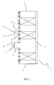
- a section of column 1 to protect against external aggressions comprises a cylindrical shell containing three modules of trays or structured packings 3,4,5.
- An inlet or outlet pipe 6 penetrates through the shell between the modules 3 and 4. This pipe is closed by a solid flange ensuring the sealing thereof.
- the two openings of the ferrule are closed by thin sheet disks which seals the section without the mechanical strength.
- a circuit 10 puts the internal atmosphere of the section 1 into communication with the outside atmosphere via a purifier 11.
- the purifier 11 includes an opening 12 for gas exchange with the atmosphere and contains a material 13 for trapping atmospheric impurities.
- the operation of the assembly will be illustrated by taking a nonlimiting example relating to the stopping of the atmospheric humidity during a storage period of a column section, the incoming and outgoing flows then being directly related to the variations daytime and nighttime temperature.
- the internal volume sealed from the outside is approximately 100 m 3 .
- the quantities of air entering and leaving the volume are of the order of 7 to 8 Nm 3 .
- the amount of water vapor that can enter the equipment each cycle is one hundred grams. This quantity is large enough to eventually provoke corrosions, poison catalysts, maintain undesirable chemical reactions but it is on the other hand sufficiently weak to be stopped even completely on an alumina or silica gel type adsorbent. A few kilograms of adsorbents can easily retain this amount of water and dry the gas entering the equipment.
- the interesting phenomenon is that the wet gas passes on the adsorbent when the temperature cools, which is favorable to the adsorption, that is to say in this case when the water stops. Conversely, the dry gas flows from the equipment to the outside environment while the temperature is warming, which is favorable to the desorption, that is to say the regeneration of the adsorbent.
- the temperature of the adsorbent will rapidly follow the changes in outside temperature, heating up faster than the interior of the equipment whose capacity heat is more important. This means that at the end of each daily cycle, the adsorbent will be well regenerated because it has seen the regeneration of the same amount of gas in adsorption at a higher temperature. The few kilograms of adsorbent mentioned above will therefore be sufficient regardless of the duration of storage or transport.
- the adsorbents can be placed in a pipe section of 10 cm in diameter for example, maintained between two grids or in boxes or envelopes of various shapes.
- the main axis of the trap is vertical so that the flow of air through the adsorbents is done without driving to short-circuit the trap.
- the shape of the trap will be adapted to be effective in both positions, or two mounting positions will be provided from the design stage.
Landscapes
- Engineering & Computer Science (AREA)
- Chemical & Material Sciences (AREA)
- Chemical Kinetics & Catalysis (AREA)
- Thermal Sciences (AREA)
- General Engineering & Computer Science (AREA)
- Mechanical Engineering (AREA)
- Physics & Mathematics (AREA)
- Analytical Chemistry (AREA)
- General Chemical & Material Sciences (AREA)
- Oil, Petroleum & Natural Gas (AREA)
- Solid-Sorbent Or Filter-Aiding Compositions (AREA)
- Separation Of Gases By Adsorption (AREA)
- Drying Of Gases (AREA)
- Casings For Electric Apparatus (AREA)
Abstract
Description
- La présente invention est relative à un équipement industriel comportant un dispositif de protection des parties internes particulièrement pendant les périodes de construction, stockage ou de transport.
- Les parties internes d'équipements industriels, tels que colonne à distiller, réservoir, réacteur, adsorbeur, sont évidemment bien adaptées aux conditions opératoires de l'équipement en question mais peuvent être sensibles à un contact prolongé avec l'atmosphère ambiante. Les problèmes évoqués pouvant être dus aux constituants habituels (humidité, dioxyde de carbone, oxygène...) ou à des polluants secondaires tels qu'on peut trouver dans les zones industrielles (produits soufrés, oxydes d'azote...) ou par exemple en ambiance marine.
- On peut citer l'oxydation de l'acier carbone en présence d'oxygène et d'humidité, la formation d'hydrogène dans les mêmes conditions et en présence de diverses impuretés à partir d'aluminium. On sait également qu'il faut éviter toute trace de NH3 en présence de cuivre et que les catalyseurs sont empoisonnés par un grand nombre de constituants susceptibles de se trouver dans une atmosphère polluée ou marine ( composés soufrés, chlorés, NOx...).
- Il existe donc un risque réel de pollution, de corrosion, de création de composés indésirables voire dangereux si on laisse exposé à l'air des équipements tels les colonnes à distiller, en particulier comportant des plateaux en aluminium ou en cuivre, les réacteurs, les réservoirs susceptibles de voir leurs internes s'oxyde. Ce risque est surtout important pendant la fabrication, le stockage, le transport, le montage, c'est à dire lorsque ces équipements ne sont pas encore installés sur leur site définitif, et reliés aux équipements amont et aval.
- Des solutions existent pour pallier ces problèmes. Ainsi, la fabrication peut s'effectuer en atelier à atmosphère contrôlée avec filtration de l'air. Pendant le stockage et le transport, la protection consiste à obturer les entrées et sorties de l'équipement, par exemple en installant des brides pleines au niveau des tuyauteries.
- Lorsqu'il s'agit d'un tronçon d'un équipement fabriqué par morceaux par exemple à cause de ses dimensions trop importantes, il est courant de souder un fond temporaire à l'extrémité libre. C'est le cas pour certaine colonne à distiller dont la hauteur finale est de plusieurs dizaines de mètres. Cette obturation se rajoute alors au bouchage plus classique des diverses tuyauteries d'entrée/sortie de l'équipement comme décrit plus haut. Les fonds elliptiques ou hémisphériques devenant très onéreux, dès lors que leur diamètre augmente, il est aussi coutumier de souder un simple disque de façon également temporaire pour sécuriser les équipements durant le stockage et le transport. Cette solution, moins onéreuse au départ, est difficilement extrapolable à de gros équipements.
- On peut calculer en effet les efforts susceptibles d'être appliqués sur l'obturateur.
- Les efforts s'exerçant sur le fond vont en effet provenir des différences de pression interne/ externe. L'écart de pression peut venir des conditions climatiques via l'effet direct de la pression atmosphérique mais aussi des variations de température. Des variations de 20°C vont entraîner un écart de pression de l'ordre de 80 mbar. Un équipement stocké en été dans un pays « froid » pourra être très largement sous vide en hiver. De telles dépressions ou surpressions ne sont pas supportables mécaniquement par de simples disques de tôle mince dès qu'il s'agit d'équipement de taille importante. Or, pour mémoire, il est classique de stocker et transporter des tronçons de colonne à distiller de plus de 5 m de diamètre.
- Lors d'un transport les différences d'altitude le long d'un trajet peuvent causer des effets analogues. Il peut être alors excessivement coûteux de prévoir des fonds elliptiques voire hémisphériques de ces diamètres ou des fonds plats très renforcés (à cause des limitations des matériels eux-mêmes, du coût de la main d'oeuvre, du surcoût du transport dû au poids et/ou dimensions additionnel(les).
- La solution préconisée ici est effectivement d'obturer par exemple une virole cylindrique de gros diamètre par un disque de tôle mince ainsi que de boucher classiquement les tuyauteries d'entrée/sortie susceptibles de se trouver sur cet équipement mais de ménager une liaison volontaire entre le volume interne ainsi délimité et l'atmosphère. Ainsi les transferts gazeux possibles dans un sens ou dans l'autre permettent à tout moment d'équilibrer les pressions interne/externe. Ces échanges se faisant par un circuit bien défini, par exemple à travers une tuyauterie, il est possible de placer sur ce circuit un ou des pièges destinés à capter tout ou au moins la majorité des constituants atmosphériques indésirables compte tenu des matériaux ou produits se trouvant à l'intérieur de l'enceinte.
- De cette façon, le système n'est pas étanche mais on contrôle les entrées d'air (dues aux variations de température et de pression) en créant volontairement au moins une fuite sur laquelle on place un épurateur.
- Selon un objet de l'invention, il est prévu un équipement industriel comprenant des parties internes disposées dans une enceinte fermée au moins temporairement par un fond de protection, les parties internes étant reliées à l'atmosphère à l'extérieur de l'enceinte essentiellement au moyen d'au moins une conduite permettant le passage d'air de l'extérieur vers les parties internes et des parties internes vers l'extérieur, la conduite contenant au moins un dispositif permettant de piéger au moins un constituant atmosphérique indésirable.
- Selon d'autres objets de l'invention, il est prévu que:
- le(s) dispositif(s) permet(tent) de piéger un constituant compris dans le groupe suivant : eau, dioxyde de carbone, oxydes d'azote, acides, oxygène, produits alcalins, hydrocarbures ;
- la conduite est une tuyauterie de l'équipement;
- la conduite est une tuyauterie de l'équipement servant à assurer le passage d'air atmosphérique à température ambiante pendant les périodes de construction, stockage ou de transport et reliée à un fluide autre que l'air atmosphérique à température ambiante en période d'opération de l'équipement ;
- l'axe principal du dispositif est vertical ;
- le dispositif piège le constituant par réaction chimique et/ou piège physiquement le constituant;
- le dispositif est un adsorbant du type zéolite, alumine activée, gel de silice ou charbon actif éventuellement dopé par des additifs;
- l'équipement est un tronçon de colonne de distillation, un réacteur chimique, un adsorbeur ou un réservoir.
- On pourra ainsi utiliser un adsorbant ( charbon actif ou gel de silice) dopé chimiquement pour arrêter des traces de produits chlorés, de l'HCI.... Pour d'autres constituants présents en quantité plus importante, on utilisera l'effet d'adsorption/désorption.
- Il faut effectivement noter que les flux en circulation à travers le piège vont être d'une part alternés, d'autre part ponctuellement faibles.
- L'invention sera décrite en plus de détail en de référant à la figure qui illustre une colonne de distillation selon l'invention.
- Un tronçon de colonne 1 à protéger des agressions extérieures comprend une virole cylindrique contenant trois modules de plateaux ou de garnissages structurés 3,4,5. Une tubulure d'entrée ou de sortie 6 pénètre à travers la virole entre les modules 3 et 4. Cette tubulure est fermée par une bride pleine assurant l'étanchéité de celle-ci.
- Pendant le transport de la tronçon, les deux ouvertures de la virole sont fermées par des disques de tôle mince qui assure l'étanchéité du tronçon sans présenter pour autant de la résistance mécanique.
- Un circuit 10 met en communication l'atmosphère interne du tronçon 1 et l'atmosphère extérieur via un épurateur 11.
- L'épurateur 11 comprend une ouverture 12 permettant des échanges gazeux avec l'atmosphère et contient un matériau 13 destiné à piéger les impuretés atmosphériques.
- On va illustrer le fonctionnement de l'ensemble en prenant un exemple - non limitatif - relatif à l'arrêt de l'humidité atmosphérique pendant une période de stockage d'un tronçon de colonne, les flux entrant et sortant étant alors directement liés aux variations de température diurne et nocturne.
- Dans l'hypothèse d'un tronçon de colonne de diamètre 4 m et de longueur 8 m, le volume interne isolé de façon étanche de l'extérieur(sauf à travers la tuyauterie d'équilibrage des pressions) est d'environ 100 m3. En supposant un écart de température entre la nuit et le jour de 20°C, les quantités d'air entrant puis sortant du volume sont de l'ordre de 7 à 8 Nm3.
- En supposant une humidité relative moyenne de l'ordre de 60 ou 70%, la quantité de vapeur d'eau pouvant entrer dans l'équipement chaque cycle est d'une centaine de grammes. Cette quantité est suffisamment importante pour provoquer à terme des corrosions, empoisonner des catalyseurs, entretenir des réactions chimiques indésirables mais elle est par contre suffisamment faible pour être arrêtée même totalement sur un adsorbant du type alumine ou gel de silice. Quelques kilogrammes d'adsorbants permettent de retenir sans problème cette quantité d'eau et de sécher le gaz pénétrant dans l'équipement.
- Le phénomène intéressant est que le gaz humide passe sur l'adsorbant quand la température se refroidit, ce qui est favorable à l'adsorption, c'est à dire dans ce cas à l'arrêt de l'eau. A l'inverse, le gaz sec circule de l'équipement vers le milieu extérieur alors que la température se réchauffe, ce qui est favorable à la désorption, c'est à dire à la régénération de l'adsorbant.
- En particulier, si on installe le piège contenant l'adsorbant à l'extérieur de l'équipement, la température de l'adsorbant suivra rapidement les variations de température extérieure, se réchauffant plus rapidement que la partie intérieure de l'équipement dont la capacité calorifique est plus importante. Cela signifie qu'à la fin de chaque cycle journalier, l'adsorbant sera bien régénéré car il aura vu passer en régénération la même quantité de gaz qu'en adsorption à une température plus élevée. Les quelques kilogrammes d'adsorbant mentionné plus haut seront donc suffisant quelle que soit la durée du stockage ou du transport.
- On constate également que les effets de pression (variation de la pression barométrique, altitude variable) sont favorables à la régénération de l'adsorbant : l'air humide entre lorsque la pression s'élève et sort quand la pression s'abaisse...c'est en quelque sorte, le principe même des procédés PSA.
- Il est possible d'installer en série plusieurs lits d'adsorbants variés suivant les composés que l'on veut retenir. On peut imaginer installer quelques kilogrammes d'alumine activée, et quelques centaines de grammes de tamis échangé au baryum ou de zéolite spécifique, de charbon dopé pour arrêter, en plus de l'humidité atmosphérique, par exemple des traces d'HCl (piégeage chimique sur alumine), de NH3, d'hydrocarbures...
- Les adsorbants peuvent être placés dans un tronçon de tuyauterie de 10 cm de diamètre par exemple, maintenu entre deux grilles ou dans des boîtes ou enveloppes de forme variée.
- De façon préférentielle, on fera en sorte que l'axe principal du piège soit vertical afin que la circulation de l'air à travers les adsorbants se fasse sans conduite pour court-circuiter le piège. Si deux positions sont prévues pour l'équipement, par exemple debout pour le stockage et couché pour le transport, la forme du piège sera adaptée pour être efficace dans les deux positions, ou deux positions de fixation seront prévues dès la conception.
Claims (8)
- Equipement industriel (1) comprenant des parties internes (3, 4, 5) disposées dans une enceinte (2, 8, 9) fermée au moins temporairement par un fond de protection (8, 9), les parties internes étant reliées à l'atmosphère à l'extérieur de l'enceinte essentiellement au moyen d'une seule conduite (6) permettant le passage d'air de l'extérieur vers les parties internes et des parties internes vers l'extérieur, la conduite contenant au moins un dispositif (11) permettant de piéger au moins un constituant atmosphérique indésirable.
- Equipement selon la revendication 1 dans lequel le(s) dispositif(s) (11) permet(tent) de piéger un constituant compris dans le groupe suivant : eau, dioxyde de carbone, oxydes d'azote, acides, oxygène, produits alcalins, hydrocarbures.
- Equipement selon la revendication 1 ou 2 dans lequel la conduite (6) est une tuyauterie de l'équipement.
- Equipement selon la revendication 3 dans lequel la conduite (6) est une tuyauterie de l'équipement servant à assurer le passage d'air atmosphérique à température ambiante pendant les périodes de construction, stockage ou de transport et reliée à un fluide autre que l'air atmosphérique à température ambiante en période d'opération de l'équipement.
- Equipement selon l'une des revendications 3 ou 4 dans lequel l'axe principal du dispositif (11) est vertical.
- Equipement selon l'une des revendications précédentes dans lequel le dispositif (11) piège le constituant par réaction chimique et/ou piège physiquement le constituant.
- Equipement selon l'une des revendications précédentes dans lequel le dispositif (11) contient un adsorbant du type zéolite, alumine activée, gel de silice ou charbon actif éventuellement dopé par des additifs.
- Equipement selon l'une des revendications précédentes étant un tronçon de colonne de distillation, un réacteur chimique, un adsorbeur ou un réservoir.
Applications Claiming Priority (1)
| Application Number | Priority Date | Filing Date | Title |
|---|---|---|---|
| FR0655772A FR2910343B1 (fr) | 2006-12-21 | 2006-12-21 | Equipement industriel comportant un dispositif de protection des parties internes |
Publications (2)
| Publication Number | Publication Date |
|---|---|
| EP1946818A1 true EP1946818A1 (fr) | 2008-07-23 |
| EP1946818B1 EP1946818B1 (fr) | 2012-10-03 |
Family
ID=38261639
Family Applications (1)
| Application Number | Title | Priority Date | Filing Date |
|---|---|---|---|
| EP07301628A Not-in-force EP1946818B1 (fr) | 2006-12-21 | 2007-12-05 | Procédé de transport d'un tronçon de colonne de distillation |
Country Status (3)
| Country | Link |
|---|---|
| US (1) | US20090000483A1 (fr) |
| EP (1) | EP1946818B1 (fr) |
| FR (1) | FR2910343B1 (fr) |
Citations (4)
| Publication number | Priority date | Publication date | Assignee | Title |
|---|---|---|---|---|
| US3349920A (en) * | 1965-08-18 | 1967-10-31 | Waters Associates Inc | System for protecting liquid chromatography columns |
| RU2153926C1 (ru) * | 2000-02-01 | 2000-08-10 | Закрытое акционерное общество "Металлхим-Прогресс" | Устройство и способ сорбционной нейтрализации газов |
| GB2348378A (en) * | 1999-03-25 | 2000-10-04 | Korea M A T Co Ltd | Multi-cartridge adsorbent gas scrubber |
| WO2004074603A1 (fr) * | 2003-02-18 | 2004-09-02 | Air Products And Chemicals, Inc. | Appareil de distillation et son procede de transport |
Family Cites Families (1)
| Publication number | Priority date | Publication date | Assignee | Title |
|---|---|---|---|---|
| US2794183A (en) * | 1954-11-04 | 1957-05-28 | Phillips Petroleum Co | Breathing tank odor filter and warning device |
-
2006
- 2006-12-21 FR FR0655772A patent/FR2910343B1/fr not_active Expired - Fee Related
-
2007
- 2007-12-05 EP EP07301628A patent/EP1946818B1/fr not_active Not-in-force
- 2007-12-19 US US11/959,734 patent/US20090000483A1/en not_active Abandoned
Patent Citations (4)
| Publication number | Priority date | Publication date | Assignee | Title |
|---|---|---|---|---|
| US3349920A (en) * | 1965-08-18 | 1967-10-31 | Waters Associates Inc | System for protecting liquid chromatography columns |
| GB2348378A (en) * | 1999-03-25 | 2000-10-04 | Korea M A T Co Ltd | Multi-cartridge adsorbent gas scrubber |
| RU2153926C1 (ru) * | 2000-02-01 | 2000-08-10 | Закрытое акционерное общество "Металлхим-Прогресс" | Устройство и способ сорбционной нейтрализации газов |
| WO2004074603A1 (fr) * | 2003-02-18 | 2004-09-02 | Air Products And Chemicals, Inc. | Appareil de distillation et son procede de transport |
Also Published As
| Publication number | Publication date |
|---|---|
| FR2910343B1 (fr) | 2010-11-05 |
| FR2910343A1 (fr) | 2008-06-27 |
| EP1946818B1 (fr) | 2012-10-03 |
| US20090000483A1 (en) | 2009-01-01 |
Similar Documents
| Publication | Publication Date | Title |
|---|---|---|
| US10232305B2 (en) | Direct air capture device | |
| EP2501461B1 (fr) | Dispositif d'absorption d'eau d'un gaz et son utilisation | |
| EP0298976A1 (fr) | Appareil servant a recuperer la chaleur provenant de gaz de fumee et a nettoyer lesdits gaz. | |
| CN102310783B (zh) | 锂离子电池故障缓解 | |
| KR101654193B1 (ko) | 대기오염 측정 분석을 위한 음페바 효과를 이용한 전처리 장치 및 방법 | |
| TWI261529B (en) | Built in purifier for reactive gases | |
| EP1583598B1 (fr) | Filtre | |
| EP1946818B1 (fr) | Procédé de transport d'un tronçon de colonne de distillation | |
| FR2604100A1 (fr) | Dispositif d'enceinte pour adsorbeurs ou evaporateurs sous vide | |
| US20180143105A1 (en) | Pretreatment apparatus and method for analysing air pollution detection | |
| FR2698160A1 (fr) | Procédé et dispositif pour le traitement des atmosphères de travail utilisant un échangeur cyclonique. | |
| EP1243909A1 (fr) | Ligne de prélèvement d'échantillons d'effluents gazeux chauds en émission diffuse | |
| KR20230151321A (ko) | 고습도 시료가스를 위한 수직형 수분 전처리장치의 재생장치 및 재생방법 | |
| CA2468638A1 (fr) | Analyseur de gaz de combustion | |
| CN110620203A (zh) | 电池包通气干燥过滤系统 | |
| WO2012007673A1 (fr) | Adsorbeur avec revêtement interne | |
| FR3103477A1 (fr) | Procédé de protection d’un équipement industriel ayant au moins une ouverture | |
| WO2017064427A1 (fr) | Dispositif d'epuration vertical | |
| FR2989454A1 (fr) | Installation de compression d'un flux gazeux humide | |
| SE2151429A1 (en) | Device for storing batteries | |
| CA2561664C (fr) | Dispositif de deviation d'un flux gazeux par un registre drapeau a clapet unique | |
| EP2877270A1 (fr) | INSTALLATION DE PURIFICATION D'UN FLUX GAZEUX HUMIDE, CONTENANT DU CO2 ET DES NOx& xA; | |
| US20250099900A1 (en) | Carbon capture system | |
| CN216935222U (zh) | 一种焦油分离装置 | |
| CN206377266U (zh) | 一种压力容器的爆破片背压排放系统 |
Legal Events
| Date | Code | Title | Description |
|---|---|---|---|
| PUAI | Public reference made under article 153(3) epc to a published international application that has entered the european phase |
Free format text: ORIGINAL CODE: 0009012 |
|
| AK | Designated contracting states |
Kind code of ref document: A1 Designated state(s): AT BE BG CH CY CZ DE DK EE ES FI FR GB GR HU IE IS IT LI LT LU LV MC MT NL PL PT RO SE SI SK TR |
|
| AX | Request for extension of the european patent |
Extension state: AL BA HR MK RS |
|
| 17P | Request for examination filed |
Effective date: 20090123 |
|
| 17Q | First examination report despatched |
Effective date: 20090227 |
|
| AKX | Designation fees paid |
Designated state(s): AT BE BG CH CY CZ DE DK EE ES FI FR GB GR HU IE IS IT LI LT LU LV MC MT NL PL PT RO SE SI SK TR |
|
| RTI1 | Title (correction) |
Free format text: TRANSPORT METHOD OF A DISTILLATION COLUMN SECTION |
|
| GRAP | Despatch of communication of intention to grant a patent |
Free format text: ORIGINAL CODE: EPIDOSNIGR1 |
|
| GRAS | Grant fee paid |
Free format text: ORIGINAL CODE: EPIDOSNIGR3 |
|
| GRAA | (expected) grant |
Free format text: ORIGINAL CODE: 0009210 |
|
| AK | Designated contracting states |
Kind code of ref document: B1 Designated state(s): AT BE BG CH CY CZ DE DK EE ES FI FR GB GR HU IE IS IT LI LT LU LV MC MT NL PL PT RO SE SI SK TR |
|
| REG | Reference to a national code |
Ref country code: GB Ref legal event code: FG4D Free format text: NOT ENGLISH |
|
| REG | Reference to a national code |
Ref country code: AT Ref legal event code: REF Ref document number: 577704 Country of ref document: AT Kind code of ref document: T Effective date: 20121015 Ref country code: CH Ref legal event code: EP |
|
| REG | Reference to a national code |
Ref country code: IE Ref legal event code: FG4D Free format text: LANGUAGE OF EP DOCUMENT: FRENCH |
|
| REG | Reference to a national code |
Ref country code: DE Ref legal event code: R096 Ref document number: 602007025837 Country of ref document: DE Effective date: 20121129 |
|
| REG | Reference to a national code |
Ref country code: AT Ref legal event code: MK05 Ref document number: 577704 Country of ref document: AT Kind code of ref document: T Effective date: 20121003 |
|
| PG25 | Lapsed in a contracting state [announced via postgrant information from national office to epo] |
Ref country code: SI Free format text: LAPSE BECAUSE OF FAILURE TO SUBMIT A TRANSLATION OF THE DESCRIPTION OR TO PAY THE FEE WITHIN THE PRESCRIBED TIME-LIMIT Effective date: 20121003 |
|
| PGFP | Annual fee paid to national office [announced via postgrant information from national office to epo] |
Ref country code: GB Payment date: 20121220 Year of fee payment: 6 Ref country code: IT Payment date: 20121221 Year of fee payment: 6 |
|
| REG | Reference to a national code |
Ref country code: NL Ref legal event code: VDEP Effective date: 20121003 |
|
| REG | Reference to a national code |
Ref country code: LT Ref legal event code: MG4D |
|
| PG25 | Lapsed in a contracting state [announced via postgrant information from national office to epo] |
Ref country code: ES Free format text: LAPSE BECAUSE OF FAILURE TO SUBMIT A TRANSLATION OF THE DESCRIPTION OR TO PAY THE FEE WITHIN THE PRESCRIBED TIME-LIMIT Effective date: 20130114 Ref country code: LT Free format text: LAPSE BECAUSE OF FAILURE TO SUBMIT A TRANSLATION OF THE DESCRIPTION OR TO PAY THE FEE WITHIN THE PRESCRIBED TIME-LIMIT Effective date: 20121003 Ref country code: FI Free format text: LAPSE BECAUSE OF FAILURE TO SUBMIT A TRANSLATION OF THE DESCRIPTION OR TO PAY THE FEE WITHIN THE PRESCRIBED TIME-LIMIT Effective date: 20121003 Ref country code: NL Free format text: LAPSE BECAUSE OF FAILURE TO SUBMIT A TRANSLATION OF THE DESCRIPTION OR TO PAY THE FEE WITHIN THE PRESCRIBED TIME-LIMIT Effective date: 20121003 Ref country code: IS Free format text: LAPSE BECAUSE OF FAILURE TO SUBMIT A TRANSLATION OF THE DESCRIPTION OR TO PAY THE FEE WITHIN THE PRESCRIBED TIME-LIMIT Effective date: 20130203 Ref country code: SE Free format text: LAPSE BECAUSE OF FAILURE TO SUBMIT A TRANSLATION OF THE DESCRIPTION OR TO PAY THE FEE WITHIN THE PRESCRIBED TIME-LIMIT Effective date: 20121003 |
|
| PGFP | Annual fee paid to national office [announced via postgrant information from national office to epo] |
Ref country code: DE Payment date: 20121220 Year of fee payment: 6 |
|
| PG25 | Lapsed in a contracting state [announced via postgrant information from national office to epo] |
Ref country code: PT Free format text: LAPSE BECAUSE OF FAILURE TO SUBMIT A TRANSLATION OF THE DESCRIPTION OR TO PAY THE FEE WITHIN THE PRESCRIBED TIME-LIMIT Effective date: 20130204 Ref country code: CY Free format text: LAPSE BECAUSE OF FAILURE TO SUBMIT A TRANSLATION OF THE DESCRIPTION OR TO PAY THE FEE WITHIN THE PRESCRIBED TIME-LIMIT Effective date: 20121003 Ref country code: LV Free format text: LAPSE BECAUSE OF FAILURE TO SUBMIT A TRANSLATION OF THE DESCRIPTION OR TO PAY THE FEE WITHIN THE PRESCRIBED TIME-LIMIT Effective date: 20121003 Ref country code: PL Free format text: LAPSE BECAUSE OF FAILURE TO SUBMIT A TRANSLATION OF THE DESCRIPTION OR TO PAY THE FEE WITHIN THE PRESCRIBED TIME-LIMIT Effective date: 20121003 Ref country code: GR Free format text: LAPSE BECAUSE OF FAILURE TO SUBMIT A TRANSLATION OF THE DESCRIPTION OR TO PAY THE FEE WITHIN THE PRESCRIBED TIME-LIMIT Effective date: 20130104 |
|
| PG25 | Lapsed in a contracting state [announced via postgrant information from national office to epo] |
Ref country code: AT Free format text: LAPSE BECAUSE OF FAILURE TO SUBMIT A TRANSLATION OF THE DESCRIPTION OR TO PAY THE FEE WITHIN THE PRESCRIBED TIME-LIMIT Effective date: 20121003 |
|
| BERE | Be: lapsed |
Owner name: L'AIR LIQUIDE, S.A. POUR L'ETUDE ET L'EXPLOITATIO Effective date: 20121231 |
|
| PG25 | Lapsed in a contracting state [announced via postgrant information from national office to epo] |
Ref country code: MC Free format text: LAPSE BECAUSE OF NON-PAYMENT OF DUE FEES Effective date: 20121231 Ref country code: EE Free format text: LAPSE BECAUSE OF FAILURE TO SUBMIT A TRANSLATION OF THE DESCRIPTION OR TO PAY THE FEE WITHIN THE PRESCRIBED TIME-LIMIT Effective date: 20121003 Ref country code: SK Free format text: LAPSE BECAUSE OF FAILURE TO SUBMIT A TRANSLATION OF THE DESCRIPTION OR TO PAY THE FEE WITHIN THE PRESCRIBED TIME-LIMIT Effective date: 20121003 Ref country code: CZ Free format text: LAPSE BECAUSE OF FAILURE TO SUBMIT A TRANSLATION OF THE DESCRIPTION OR TO PAY THE FEE WITHIN THE PRESCRIBED TIME-LIMIT Effective date: 20121003 Ref country code: BG Free format text: LAPSE BECAUSE OF FAILURE TO SUBMIT A TRANSLATION OF THE DESCRIPTION OR TO PAY THE FEE WITHIN THE PRESCRIBED TIME-LIMIT Effective date: 20130103 Ref country code: DK Free format text: LAPSE BECAUSE OF FAILURE TO SUBMIT A TRANSLATION OF THE DESCRIPTION OR TO PAY THE FEE WITHIN THE PRESCRIBED TIME-LIMIT Effective date: 20121003 |
|
| REG | Reference to a national code |
Ref country code: CH Ref legal event code: PL |
|
| PLBE | No opposition filed within time limit |
Free format text: ORIGINAL CODE: 0009261 |
|
| STAA | Information on the status of an ep patent application or granted ep patent |
Free format text: STATUS: NO OPPOSITION FILED WITHIN TIME LIMIT |
|
| PG25 | Lapsed in a contracting state [announced via postgrant information from national office to epo] |
Ref country code: RO Free format text: LAPSE BECAUSE OF FAILURE TO SUBMIT A TRANSLATION OF THE DESCRIPTION OR TO PAY THE FEE WITHIN THE PRESCRIBED TIME-LIMIT Effective date: 20121003 |
|
| 26N | No opposition filed |
Effective date: 20130704 |
|
| REG | Reference to a national code |
Ref country code: IE Ref legal event code: MM4A |
|
| REG | Reference to a national code |
Ref country code: FR Ref legal event code: ST Effective date: 20130830 |
|
| PG25 | Lapsed in a contracting state [announced via postgrant information from national office to epo] |
Ref country code: BE Free format text: LAPSE BECAUSE OF NON-PAYMENT OF DUE FEES Effective date: 20121231 |
|
| PG25 | Lapsed in a contracting state [announced via postgrant information from national office to epo] |
Ref country code: CH Free format text: LAPSE BECAUSE OF NON-PAYMENT OF DUE FEES Effective date: 20121231 Ref country code: IE Free format text: LAPSE BECAUSE OF NON-PAYMENT OF DUE FEES Effective date: 20121205 Ref country code: LI Free format text: LAPSE BECAUSE OF NON-PAYMENT OF DUE FEES Effective date: 20121231 |
|
| REG | Reference to a national code |
Ref country code: DE Ref legal event code: R097 Ref document number: 602007025837 Country of ref document: DE Effective date: 20130704 |
|
| PG25 | Lapsed in a contracting state [announced via postgrant information from national office to epo] |
Ref country code: MT Free format text: LAPSE BECAUSE OF FAILURE TO SUBMIT A TRANSLATION OF THE DESCRIPTION OR TO PAY THE FEE WITHIN THE PRESCRIBED TIME-LIMIT Effective date: 20121003 Ref country code: FR Free format text: LAPSE BECAUSE OF NON-PAYMENT OF DUE FEES Effective date: 20130102 |
|
| PG25 | Lapsed in a contracting state [announced via postgrant information from national office to epo] |
Ref country code: TR Free format text: LAPSE BECAUSE OF FAILURE TO SUBMIT A TRANSLATION OF THE DESCRIPTION OR TO PAY THE FEE WITHIN THE PRESCRIBED TIME-LIMIT Effective date: 20121003 |
|
| PG25 | Lapsed in a contracting state [announced via postgrant information from national office to epo] |
Ref country code: LU Free format text: LAPSE BECAUSE OF NON-PAYMENT OF DUE FEES Effective date: 20121205 |
|
| REG | Reference to a national code |
Ref country code: DE Ref legal event code: R119 Ref document number: 602007025837 Country of ref document: DE |
|
| PG25 | Lapsed in a contracting state [announced via postgrant information from national office to epo] |
Ref country code: HU Free format text: LAPSE BECAUSE OF FAILURE TO SUBMIT A TRANSLATION OF THE DESCRIPTION OR TO PAY THE FEE WITHIN THE PRESCRIBED TIME-LIMIT Effective date: 20071205 |
|
| GBPC | Gb: european patent ceased through non-payment of renewal fee |
Effective date: 20131205 |
|
| REG | Reference to a national code |
Ref country code: DE Ref legal event code: R119 Ref document number: 602007025837 Country of ref document: DE Effective date: 20140701 |
|
| PG25 | Lapsed in a contracting state [announced via postgrant information from national office to epo] |
Ref country code: DE Free format text: LAPSE BECAUSE OF NON-PAYMENT OF DUE FEES Effective date: 20140701 |
|
| PG25 | Lapsed in a contracting state [announced via postgrant information from national office to epo] |
Ref country code: GB Free format text: LAPSE BECAUSE OF NON-PAYMENT OF DUE FEES Effective date: 20131205 |
|
| PG25 | Lapsed in a contracting state [announced via postgrant information from national office to epo] |
Ref country code: IT Free format text: LAPSE BECAUSE OF NON-PAYMENT OF DUE FEES Effective date: 20131231 |
|
| PG25 | Lapsed in a contracting state [announced via postgrant information from national office to epo] |
Ref country code: IT Free format text: LAPSE BECAUSE OF NON-PAYMENT OF DUE FEES Effective date: 20131205 |