EP1946634A1 - System for controlling incident light - Google Patents
System for controlling incident light Download PDFInfo
- Publication number
- EP1946634A1 EP1946634A1 EP07100675A EP07100675A EP1946634A1 EP 1946634 A1 EP1946634 A1 EP 1946634A1 EP 07100675 A EP07100675 A EP 07100675A EP 07100675 A EP07100675 A EP 07100675A EP 1946634 A1 EP1946634 A1 EP 1946634A1
- Authority
- EP
- European Patent Office
- Prior art keywords
- panels
- streaming
- liquid layer
- roof
- drain
- Prior art date
- Legal status (The legal status is an assumption and is not a legal conclusion. Google has not performed a legal analysis and makes no representation as to the accuracy of the status listed.)
- Withdrawn
Links
- 239000007788 liquid Substances 0.000 claims abstract description 26
- 230000001143 conditioned effect Effects 0.000 claims abstract description 10
- 238000012216 screening Methods 0.000 claims abstract description 8
- 238000001514 detection method Methods 0.000 claims abstract description 7
- XLYOFNOQVPJJNP-UHFFFAOYSA-N water Substances O XLYOFNOQVPJJNP-UHFFFAOYSA-N 0.000 claims abstract description 6
- 235000008733 Citrus aurantifolia Nutrition 0.000 claims abstract description 4
- 235000011941 Tilia x europaea Nutrition 0.000 claims abstract description 4
- 239000004571 lime Substances 0.000 claims abstract description 4
- 239000000203 mixture Substances 0.000 claims abstract description 3
- 239000003795 chemical substances by application Substances 0.000 claims description 6
- 150000001875 compounds Chemical class 0.000 claims description 2
- 238000009423 ventilation Methods 0.000 description 6
- 230000005855 radiation Effects 0.000 description 3
- 241000196324 Embryophyta Species 0.000 description 2
- 238000001816 cooling Methods 0.000 description 2
- 230000000694 effects Effects 0.000 description 2
- 235000009849 Cucumis sativus Nutrition 0.000 description 1
- 240000008067 Cucumis sativus Species 0.000 description 1
- 238000000149 argon plasma sintering Methods 0.000 description 1
- 230000003247 decreasing effect Effects 0.000 description 1
- 239000011521 glass Substances 0.000 description 1
- 238000003306 harvesting Methods 0.000 description 1
- 238000004519 manufacturing process Methods 0.000 description 1
Images

Classifications
-
- A—HUMAN NECESSITIES
- A01—AGRICULTURE; FORESTRY; ANIMAL HUSBANDRY; HUNTING; TRAPPING; FISHING
- A01G—HORTICULTURE; CULTIVATION OF VEGETABLES, FLOWERS, RICE, FRUIT, VINES, HOPS OR SEAWEED; FORESTRY; WATERING
- A01G9/00—Cultivation in receptacles, forcing-frames or greenhouses; Edging for beds, lawn or the like
- A01G9/22—Shades or blinds for greenhouses, or the like
-
- Y—GENERAL TAGGING OF NEW TECHNOLOGICAL DEVELOPMENTS; GENERAL TAGGING OF CROSS-SECTIONAL TECHNOLOGIES SPANNING OVER SEVERAL SECTIONS OF THE IPC; TECHNICAL SUBJECTS COVERED BY FORMER USPC CROSS-REFERENCE ART COLLECTIONS [XRACs] AND DIGESTS
- Y02—TECHNOLOGIES OR APPLICATIONS FOR MITIGATION OR ADAPTATION AGAINST CLIMATE CHANGE
- Y02A—TECHNOLOGIES FOR ADAPTATION TO CLIMATE CHANGE
- Y02A40/00—Adaptation technologies in agriculture, forestry, livestock or agroalimentary production
- Y02A40/10—Adaptation technologies in agriculture, forestry, livestock or agroalimentary production in agriculture
- Y02A40/25—Greenhouse technology, e.g. cooling systems therefor
Definitions
- the invention concerns a system for controlling incident light into a conditioned room, like e.g. a greenhouse.
- PAR Photosynthetically Active Radiation
- a new dynamic screening should comprise folowing features:
- the present invention aims to provide a system which fulfills the preferred requirements as stated above.
- a system for controlling incident light into a conditioned room like e.g. a greenhouse, via a number of translucent panels or walls, hereinafter called panels, comprising screening means which comprise a relatively opaque - e.g. light scattering, light absorbing or light reflecting - liquid layer supplied to the respective panels by controllable streaming means, the liquid layer flowing from the streaming means towards drain means, and the streaming means, panels and drain means being arranged so that in use the liquid layer flows from the streaming means to the drain means via at least one surface, the outside and/or the inside of the panels.
- screening means which comprise a relatively opaque - e.g. light scattering, light absorbing or light reflecting - liquid layer supplied to the respective panels by controllable streaming means, the liquid layer flowing from the streaming means towards drain means, and the streaming means, panels and drain means being arranged so that in use the liquid layer flows from the streaming means to the drain means via at least one surface, the outside and/
- the streaming means, panels and drain means are arranged so that in use the liquid layer flows from the streaming means to the drain means via the outside surface of the panels.
- the liquid layer flows from the streaming means to the drain means via the inside surface of the panels.
- At least part of the panels are located on a roof of the conditioned room, as most of the incident light will come from above, viz. from the sun.
- the roof may comprise at least one - in many cases two - inclined roof part including the respective panels and the streaming means are located at the upper side of the roof.
- the drain means may reside at the lower side of the inclined roof, or still lower, e.g. at the ground level of the conditioned room (e.g. greenhouse).
- the streaming means may preferrably comprise a tube in parallel with the upper side or ridge of the roof.
- the roof includes two inclined roof parts, e.g. more or less having the shape of a saddle roof, two tubes may be installated on either side of the roof ridge, each streaming tube pouring out its liquid to one inclined roof half, via the translucent roof panel(s) towards the downsided drain means.
- the relatively opaque liquid layer preferrably comprises or is based on water and may comprise a compound or mixture of water and at least one agent.
- an agent may comprise chalk, or lime.
- the system presented here preferrably comprises control means for controlling the streaming means, as well as detection means for measuring relevant values like e.g. light, temperature, moisture content, CO2 content etc. inside and/or outside the conditioned room.
- the preferred control means may be arranged for controlling the controllable streaming means in dependency of one or more of the values measured by the detection means.
- the liquid may be cleaned and/or recondioned, buffered and - under control of the control means - repumped to the streaming means.
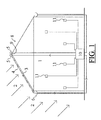
- Figure 1 shows a greenhouse 1, upon which sun light 2 may incide via a number of translucent panels or walls, for a main part via its translucent - e.g. glass - roof panels 3.
- the greenhouse 1 has to use screening means to control or manage the amount of incident sun light 2.
- the screening means comprise a relatively opaque liquid layer 4 supplied to the respective panels by controllable streaming means 5, the liquid layer flowing from the streaming means towards drain means 6, and the streaming means 5, panels 3 and drain means 6 being arranged so that in use the liquid layer flows from the streaming means to the drain means via at least one surface of the panels.
- the streaming means, panels and drain means are arranged so that in use the liquid layer flows from the streaming means to the drain means via the outside surface of the panels, located on the roof 8 of the greenhouse 1.
- the roof 8 comprises two inclined roof parts including the translucent panels 3; the streaming means 5 are located at the upper side of the roof 8.
- the streaming means in this embodiment are formed of a tube 5, extending in parallel with the upper side or ridge 9 of the roof 8 and being perforated to the declining side thus enabling that the liquid can be poured out towards to (only) one declined roof part.
- the opaque liquid layer may be based on water, compounded or mixted with one or more agents, e.g. mixt with chalk or lime, thus forming a nice white liquid layer which can be spread over the roof 8 if required, which may be judged by the greenhouse staff, manually operating the system e.g. bij starting a pump and/or opening relevant valves.
- agents e.g. mixt with chalk or lime
- control means 10 are arranged to control the streaming means 5 by controlling pumps and/or valves (not shown) and thus feeding the streaming tubes 5.
- control means 10 are connected with detection means for measuring relevant values like e.g. light, temperature, moisture content, CO2 content etc. inside and/or outside the greenhouse 1. In that way the control means are arranged for controlling the controllable streaming means in dependency of one or more of the values measured by the detection means.
- the drain 6 is located at the lower side of the translucent side panels, enabling that the liquid layer 4 also flows along the translucent side walls, thus also shielding (and colling) the side walls by means of the opaque liquid 4 supplied to those panels by the streaming relevant tube 5.
Landscapes
- Life Sciences & Earth Sciences (AREA)
- Environmental Sciences (AREA)
- Greenhouses (AREA)
Abstract
System for controlling incident light (2) into a conditioned room (1) like e.g. a greenhouse, via a number of translucent panels (3). Screening means are provided which comprise an opaque liquid layer (4) supplied to the respective panels by controllable streaming means (5) and flowing via one or both surfaces of the panel towards drain means (6). The opaque liquid layer may be a mixture of water and e.g. chalk or lime. Control means (10) may be provided for controlling the streaming means in dependency of values like e.g. light, temperature, moisture content, CO2 content etc. inside and/or outside the conditioned room, measured by detection means (11).
Description
- The invention concerns a system for controlling incident light into a conditioned room, like e.g. a greenhouse.
- During the summer months the ventilation windows etc. of greenhouses often have to be opened at maximum in order to keep the inside temperature at the right level. By such ventilation, however, the CO2 level will often drop to hardly above the atmospheric level. The effect of this could be illustrated by the following example: outside the
summer months 1 kilo of cucumbers can be harvested requiring 2800 Joule of external radiation, while during the summer months 4500 Joule may be required for 1 kilo. During the summer thus the CO2 level is an important restricting factor for the harvest. - One additional aspect is that PAR (Photosynthetically Active Radiation) light is used insufficiently. Another aspect is that present screening systems are too slow to react to the dynamics during half-clouded days.
- A new dynamic screening should comprise folowing features:
- during the summer months no more than 20% ventilation by means of greenhouse windows should be required;
- the dynamic behaviour of half-clouded days should be smoothed;
- on days having not much sun radiation (winter days, cloudy summer days) no substantial amount of light should be captured by the system;
- a new system should be applicable to existing greenhouses.
- The present invention aims to provide a system which fulfills the preferred requirements as stated above. According to the invention it is preferred to provide a system for controlling incident light into a conditioned room, like e.g. a greenhouse, via a number of translucent panels or walls, hereinafter called panels, comprising screening means which comprise a relatively opaque - e.g. light scattering, light absorbing or light reflecting - liquid layer supplied to the respective panels by controllable streaming means, the liquid layer flowing from the streaming means towards drain means, and the streaming means, panels and drain means being arranged so that in use the liquid layer flows from the streaming means to the drain means via at least one surface, the outside and/or the inside of the panels.
- Preferably, the streaming means, panels and drain means are arranged so that in use the liquid layer flows from the streaming means to the drain means via the outside surface of the panels. However, as stated, it may be preferred that, e.g. additionally, the liquid layer flows from the streaming means to the drain means via the inside surface of the panels.
- It is envsiaged that it will be preferred that at least part of the panels are located on a roof of the conditioned room, as most of the incident light will come from above, viz. from the sun.
- The roof may comprise at least one - in many cases two - inclined roof part including the respective panels and the streaming means are located at the upper side of the roof. The drain means may reside at the lower side of the inclined roof, or still lower, e.g. at the ground level of the conditioned room (e.g. greenhouse).
- The streaming means may preferrably comprise a tube in parallel with the upper side or ridge of the roof. When the roof includes two inclined roof parts, e.g. more or less having the shape of a saddle roof, two tubes may be installated on either side of the roof ridge, each streaming tube pouring out its liquid to one inclined roof half, via the translucent roof panel(s) towards the downsided drain means.
- The relatively opaque liquid layer preferrably comprises or is based on water and may comprise a compound or mixture of water and at least one agent. For example such an agent may comprise chalk, or lime.
- The system presented here preferrably comprises control means for controlling the streaming means, as well as detection means for measuring relevant values like e.g. light, temperature, moisture content, CO2 content etc. inside and/or outside the conditioned room. The preferred control means may be arranged for controlling the controllable streaming means in dependency of one or more of the values measured by the detection means.
- After the liquid has been collected by the drain means - e.g. gutters, drains etc. - the liquid may be cleaned and/or recondioned, buffered and - under control of the control means - repumped to the streaming means.
- Advantages of the system according to the invention include:
- Quick response to varying weather conditions.
- Dynamically
- Minor adaptions required to the exiting building (e.g. greenhouse).
- Double cooling effect, viz. both by screening from the heat/light source (the sun) and by cooling the surface(s) of the panel(s).
- Below are listed some estimated advantages:
- Increased CO2 concentration: +15%
- Decreased light intensity: - 5%
- Total production increase: 10%
-
Extra income 2 €/m2 in summer period - Estimated gas savings / CO2
- 20% ventilation: 100 kg/hr CO2
- 100% ventilation: 170 kg/hr CO2
- Saving by reduction of CO2 loss open air
- Extra usage by increased Co2 comsumption of the plants
- Saving by less ventilation: 0,36 €/m2
- Increased plant usage: -0,06 €/m2
-
-
Figure 1 shows an exemplary embodiment of a system according the invention. -
Figure 2 shows a slightly modified embodiment. -
Figure 1 shows agreenhouse 1, upon whichsun light 2 may incide via a number of translucent panels or walls, for a main part via its translucent - e.g. glass - roof panels 3. For reasons given in the preceding, thegreenhouse 1 has to use screening means to control or manage the amount ofincident sun light 2. - In
figure 1 the screening means comprise a relatively opaque liquid layer 4 supplied to the respective panels by controllable streaming means 5, the liquid layer flowing from the streaming means towards drain means 6, and the streaming means 5, panels 3 and drain means 6 being arranged so that in use the liquid layer flows from the streaming means to the drain means via at least one surface of the panels. Infigure 1 the streaming means, panels and drain means are arranged so that in use the liquid layer flows from the streaming means to the drain means via the outside surface of the panels, located on the roof 8 of thegreenhouse 1. - In
figure 1 the roof 8 comprises two inclined roof parts including the translucent panels 3; the streaming means 5 are located at the upper side of the roof 8. The streaming means in this embodiment are formed of a tube 5, extending in parallel with the upper side or ridge 9 of the roof 8 and being perforated to the declining side thus enabling that the liquid can be poured out towards to (only) one declined roof part. - The opaque liquid layer may be based on water, compounded or mixted with one or more agents, e.g. mixt with chalk or lime, thus forming a nice white liquid layer which can be spread over the roof 8 if required, which may be judged by the greenhouse staff, manually operating the system e.g. bij starting a pump and/or opening relevant valves.
- It is preferred, however, that the system will be operated by automatic, e.g. computerized control means 10. The control means 10 are arranged to control the streaming means 5 by controlling pumps and/or valves (not shown) and thus feeding the streaming tubes 5. Moreover, the control means 10 are connected with detection means for measuring relevant values like e.g. light, temperature, moisture content, CO2 content etc. inside and/or outside the
greenhouse 1. In that way the control means are arranged for controlling the controllable streaming means in dependency of one or more of the values measured by the detection means. - In
figure 2 thedrain 6 is located at the lower side of the translucent side panels, enabling that the liquid layer 4 also flows along the translucent side walls, thus also shielding (and colling) the side walls by means of the opaque liquid 4 supplied to those panels by the streaming relevant tube 5.
Claims (10)
- System for controlling incident light (2) into a conditioned room (1), like e.g. a greenhouse, via a number of translucent panels or walls, hereinafter called panels (3), comprising screening means which comprise a relatively opaque liquid layer (4) supplied to the respective panels by controllable streaming means (5), the liquid layer flowing from the streaming means towards drain means (6), and the streaming means, panels and drain means being arranged so that in use the liquid layer flows from the streaming means to the drain means via at least one surface of the panels.
- System according to claim 1, wherin the streaming means, panels and drain means being arranged so that in use the liquid layer flows from the streaming means to the drain means via the outside surface of the panels.
- System according to claim 2, wherein at least part of the panels are located on a roof (8) of the conditioned room.
- System according to claim 3, wherein the roof comprises at least one inclined roof part including the respective panels and the streaming means are located at the upper side of the roof.
- System according to claim 4, the streaming means comprising a tube in parallel with the upper side or ridge (9) of the roof.
- System according to claim 1, wherein the relatively opaque liquid layer comprises or is based on water.
- System according to claim 6, the relatively opaque liquid layer comprising a compound or mixture of water and at least one agent.
- System according to claim 7, one agent comprising chalk.
- System according to claim 7, one agent comprising lime.
- System according to claim 1, comprising control means (10) for controlling the streaming means, as well as detection means (11) for measuring relevant values like e.g. light, temperature, moisture content, CO2 content etc. inside and/or outside the conditioned room, and the control means being arranged for controlling the controllable streaming means in dependency of one or more of the values measured by the detection means.
Priority Applications (1)
| Application Number | Priority Date | Filing Date | Title |
|---|---|---|---|
| EP07100675A EP1946634A1 (en) | 2007-01-17 | 2007-01-17 | System for controlling incident light |
Applications Claiming Priority (1)
| Application Number | Priority Date | Filing Date | Title |
|---|---|---|---|
| EP07100675A EP1946634A1 (en) | 2007-01-17 | 2007-01-17 | System for controlling incident light |
Publications (1)
| Publication Number | Publication Date |
|---|---|
| EP1946634A1 true EP1946634A1 (en) | 2008-07-23 |
Family
ID=38222645
Family Applications (1)
| Application Number | Title | Priority Date | Filing Date |
|---|---|---|---|
| EP07100675A Withdrawn EP1946634A1 (en) | 2007-01-17 | 2007-01-17 | System for controlling incident light |
Country Status (1)
| Country | Link |
|---|---|
| EP (1) | EP1946634A1 (en) |
Cited By (3)
| Publication number | Priority date | Publication date | Assignee | Title |
|---|---|---|---|---|
| CN106419348A (en) * | 2016-11-14 | 2017-02-22 | 无锡新人居科贸有限公司 | Home intelligent plant cultivation |
| CN114153252A (en) * | 2021-11-24 | 2022-03-08 | 魏育华 | Greenhouse ventilation method and system |
| WO2025119103A1 (en) * | 2023-12-04 | 2025-06-12 | 印象认知(东莞)科技有限公司 | Solar greenhouse, manufacturing method for solar greenhouse, and plant planting device and method |
Citations (2)
| Publication number | Priority date | Publication date | Assignee | Title |
|---|---|---|---|---|
| DE738887C (en) * | 1939-04-07 | 1943-09-04 | Max Seitz | Process for shading greenhouses |
| US3016801A (en) * | 1959-11-12 | 1962-01-16 | Gysi A G Geb | Device controlling the light passing through the glass roof of a conservatory |
-
2007
- 2007-01-17 EP EP07100675A patent/EP1946634A1/en not_active Withdrawn
Patent Citations (2)
| Publication number | Priority date | Publication date | Assignee | Title |
|---|---|---|---|---|
| DE738887C (en) * | 1939-04-07 | 1943-09-04 | Max Seitz | Process for shading greenhouses |
| US3016801A (en) * | 1959-11-12 | 1962-01-16 | Gysi A G Geb | Device controlling the light passing through the glass roof of a conservatory |
Cited By (3)
| Publication number | Priority date | Publication date | Assignee | Title |
|---|---|---|---|---|
| CN106419348A (en) * | 2016-11-14 | 2017-02-22 | 无锡新人居科贸有限公司 | Home intelligent plant cultivation |
| CN114153252A (en) * | 2021-11-24 | 2022-03-08 | 魏育华 | Greenhouse ventilation method and system |
| WO2025119103A1 (en) * | 2023-12-04 | 2025-06-12 | 印象认知(东莞)科技有限公司 | Solar greenhouse, manufacturing method for solar greenhouse, and plant planting device and method |
Similar Documents
| Publication | Publication Date | Title |
|---|---|---|
| Gago et al. | Natural light controls and guides in buildings. Energy saving for electrical lighting, reduction of cooling load | |
| Syed et al. | Review of construction; geometry; heating, ventilation, and air-conditioning; and indoor climate requirements of agricultural greenhouses | |
| CN2707013Y (en) | Intelligent and ecological gutter connected greenhouse for edible fungus | |
| Chew et al. | Developing a green maintainability framework for green walls in Singapore | |
| Lin et al. | A novel cover material improves cooling energy and fertigation efficiency for glasshouse eggplant production | |
| WO2007118662A1 (en) | Process and device to accelerate growth | |
| US10576418B2 (en) | Module of ventilation and biological purification of internal and external air to an environment, and relevant method | |
| CN206620581U (en) | A kind of Chinese medicine plant greenhouse | |
| EP1946634A1 (en) | System for controlling incident light | |
| CN104620903A (en) | Large-span ventilated type solar greenhouse | |
| CN106034833A (en) | Intelligent glass greenhouse | |
| US20080245714A1 (en) | Plant-Based Sewage Treatment System for Purifying Wastewater | |
| CN104642004A (en) | Ventilation type sunlight greenhouse | |
| KR101407879B1 (en) | complex environment control method for greenhouse | |
| WO2010089144A1 (en) | Method and device for biomass-supported exhaust gas disposal, in particular co2 disposal | |
| CN109006060A (en) | A kind of fertigation intelligent control photovoltaic green-house | |
| CN209073055U (en) | A kind of fertigation intelligent control photovoltaic green-house | |
| CN106069362A (en) | A kind of view glasshouse booth | |
| CN209435893U (en) | A full sunlight steel frame greenhouse | |
| KR101463352B1 (en) | complex environment control system for greenhouse | |
| CN208691868U (en) | A kind of plant seedling stage Disease Resistance Identification canopy | |
| KR200492411Y1 (en) | A house with a normally open structure of Y-bridge roof | |
| CN206024669U (en) | Double -deck arch form greenhouse of even striding | |
| CN205812998U (en) | Warmhouse booth | |
| CN107371893A (en) | A kind of intelligent glass greenhouse |
Legal Events
| Date | Code | Title | Description |
|---|---|---|---|
| PUAI | Public reference made under article 153(3) epc to a published international application that has entered the european phase |
Free format text: ORIGINAL CODE: 0009012 |
|
| AK | Designated contracting states |
Kind code of ref document: A1 Designated state(s): AT BE BG CH CY CZ DE DK EE ES FI FR GB GR HU IE IS IT LI LT LU LV MC NL PL PT RO SE SI SK TR |
|
| AX | Request for extension of the european patent |
Extension state: AL BA HR MK RS |
|
| AKX | Designation fees paid | ||
| REG | Reference to a national code |
Ref country code: DE Ref legal event code: 8566 |
|
| STAA | Information on the status of an ep patent application or granted ep patent |
Free format text: STATUS: THE APPLICATION IS DEEMED TO BE WITHDRAWN |
|
| 18D | Application deemed to be withdrawn |
Effective date: 20090124 |