EP1945148B1 - Intervertebral prosthesis - Google Patents
Intervertebral prosthesis Download PDFInfo
- Publication number
- EP1945148B1 EP1945148B1 EP06804463.5A EP06804463A EP1945148B1 EP 1945148 B1 EP1945148 B1 EP 1945148B1 EP 06804463 A EP06804463 A EP 06804463A EP 1945148 B1 EP1945148 B1 EP 1945148B1
- Authority
- EP
- European Patent Office
- Prior art keywords
- prosthesis
- end plate
- vertebrae
- centre
- contact surface
- Prior art date
- Legal status (The legal status is an assumption and is not a legal conclusion. Google has not performed a legal analysis and makes no representation as to the accuracy of the status listed.)
- Not-in-force
Links
Images



Classifications
-
- A—HUMAN NECESSITIES
- A61—MEDICAL OR VETERINARY SCIENCE; HYGIENE
- A61F—FILTERS IMPLANTABLE INTO BLOOD VESSELS; PROSTHESES; DEVICES PROVIDING PATENCY TO, OR PREVENTING COLLAPSING OF, TUBULAR STRUCTURES OF THE BODY, e.g. STENTS; ORTHOPAEDIC, NURSING OR CONTRACEPTIVE DEVICES; FOMENTATION; TREATMENT OR PROTECTION OF EYES OR EARS; BANDAGES, DRESSINGS OR ABSORBENT PADS; FIRST-AID KITS
- A61F2/00—Filters implantable into blood vessels; Prostheses, i.e. artificial substitutes or replacements for parts of the body; Appliances for connecting them with the body; Devices providing patency to, or preventing collapsing of, tubular structures of the body, e.g. stents
- A61F2/02—Prostheses implantable into the body
- A61F2/30—Joints
- A61F2/44—Joints for the spine, e.g. vertebrae or spinal discs
-
- A—HUMAN NECESSITIES
- A61—MEDICAL OR VETERINARY SCIENCE; HYGIENE
- A61F—FILTERS IMPLANTABLE INTO BLOOD VESSELS; PROSTHESES; DEVICES PROVIDING PATENCY TO, OR PREVENTING COLLAPSING OF, TUBULAR STRUCTURES OF THE BODY, e.g. STENTS; ORTHOPAEDIC, NURSING OR CONTRACEPTIVE DEVICES; FOMENTATION; TREATMENT OR PROTECTION OF EYES OR EARS; BANDAGES, DRESSINGS OR ABSORBENT PADS; FIRST-AID KITS
- A61F2/00—Filters implantable into blood vessels; Prostheses, i.e. artificial substitutes or replacements for parts of the body; Appliances for connecting them with the body; Devices providing patency to, or preventing collapsing of, tubular structures of the body, e.g. stents
- A61F2/02—Prostheses implantable into the body
- A61F2/30—Joints
- A61F2/44—Joints for the spine, e.g. vertebrae or spinal discs
- A61F2/442—Intervertebral or spinal discs, e.g. resilient
- A61F2/4425—Intervertebral or spinal discs, e.g. resilient made of articulated components
-
- A—HUMAN NECESSITIES
- A61—MEDICAL OR VETERINARY SCIENCE; HYGIENE
- A61F—FILTERS IMPLANTABLE INTO BLOOD VESSELS; PROSTHESES; DEVICES PROVIDING PATENCY TO, OR PREVENTING COLLAPSING OF, TUBULAR STRUCTURES OF THE BODY, e.g. STENTS; ORTHOPAEDIC, NURSING OR CONTRACEPTIVE DEVICES; FOMENTATION; TREATMENT OR PROTECTION OF EYES OR EARS; BANDAGES, DRESSINGS OR ABSORBENT PADS; FIRST-AID KITS
- A61F2/00—Filters implantable into blood vessels; Prostheses, i.e. artificial substitutes or replacements for parts of the body; Appliances for connecting them with the body; Devices providing patency to, or preventing collapsing of, tubular structures of the body, e.g. stents
- A61F2/02—Prostheses implantable into the body
- A61F2/30—Joints
- A61F2/30721—Accessories
- A61F2/30734—Modular inserts, sleeves or augments, e.g. placed on proximal part of stem for fixation purposes or wedges for bridging a bone defect
-
- A—HUMAN NECESSITIES
- A61—MEDICAL OR VETERINARY SCIENCE; HYGIENE
- A61F—FILTERS IMPLANTABLE INTO BLOOD VESSELS; PROSTHESES; DEVICES PROVIDING PATENCY TO, OR PREVENTING COLLAPSING OF, TUBULAR STRUCTURES OF THE BODY, e.g. STENTS; ORTHOPAEDIC, NURSING OR CONTRACEPTIVE DEVICES; FOMENTATION; TREATMENT OR PROTECTION OF EYES OR EARS; BANDAGES, DRESSINGS OR ABSORBENT PADS; FIRST-AID KITS
- A61F2/00—Filters implantable into blood vessels; Prostheses, i.e. artificial substitutes or replacements for parts of the body; Appliances for connecting them with the body; Devices providing patency to, or preventing collapsing of, tubular structures of the body, e.g. stents
- A61F2/02—Prostheses implantable into the body
- A61F2/30—Joints
- A61F2002/30001—Additional features of subject-matter classified in A61F2/28, A61F2/30 and subgroups thereof
- A61F2002/30108—Shapes
- A61F2002/3011—Cross-sections or two-dimensional shapes
- A61F2002/30159—Concave polygonal shapes
-
- A—HUMAN NECESSITIES
- A61—MEDICAL OR VETERINARY SCIENCE; HYGIENE
- A61F—FILTERS IMPLANTABLE INTO BLOOD VESSELS; PROSTHESES; DEVICES PROVIDING PATENCY TO, OR PREVENTING COLLAPSING OF, TUBULAR STRUCTURES OF THE BODY, e.g. STENTS; ORTHOPAEDIC, NURSING OR CONTRACEPTIVE DEVICES; FOMENTATION; TREATMENT OR PROTECTION OF EYES OR EARS; BANDAGES, DRESSINGS OR ABSORBENT PADS; FIRST-AID KITS
- A61F2/00—Filters implantable into blood vessels; Prostheses, i.e. artificial substitutes or replacements for parts of the body; Appliances for connecting them with the body; Devices providing patency to, or preventing collapsing of, tubular structures of the body, e.g. stents
- A61F2/02—Prostheses implantable into the body
- A61F2/30—Joints
- A61F2002/30001—Additional features of subject-matter classified in A61F2/28, A61F2/30 and subgroups thereof
- A61F2002/30108—Shapes
- A61F2002/3011—Cross-sections or two-dimensional shapes
- A61F2002/30159—Concave polygonal shapes
- A61F2002/30172—T-shaped
-
- A—HUMAN NECESSITIES
- A61—MEDICAL OR VETERINARY SCIENCE; HYGIENE
- A61F—FILTERS IMPLANTABLE INTO BLOOD VESSELS; PROSTHESES; DEVICES PROVIDING PATENCY TO, OR PREVENTING COLLAPSING OF, TUBULAR STRUCTURES OF THE BODY, e.g. STENTS; ORTHOPAEDIC, NURSING OR CONTRACEPTIVE DEVICES; FOMENTATION; TREATMENT OR PROTECTION OF EYES OR EARS; BANDAGES, DRESSINGS OR ABSORBENT PADS; FIRST-AID KITS
- A61F2/00—Filters implantable into blood vessels; Prostheses, i.e. artificial substitutes or replacements for parts of the body; Appliances for connecting them with the body; Devices providing patency to, or preventing collapsing of, tubular structures of the body, e.g. stents
- A61F2/02—Prostheses implantable into the body
- A61F2/30—Joints
- A61F2002/30001—Additional features of subject-matter classified in A61F2/28, A61F2/30 and subgroups thereof
- A61F2002/30621—Features concerning the anatomical functioning or articulation of the prosthetic joint
- A61F2002/30649—Ball-and-socket joints
-
- A—HUMAN NECESSITIES
- A61—MEDICAL OR VETERINARY SCIENCE; HYGIENE
- A61F—FILTERS IMPLANTABLE INTO BLOOD VESSELS; PROSTHESES; DEVICES PROVIDING PATENCY TO, OR PREVENTING COLLAPSING OF, TUBULAR STRUCTURES OF THE BODY, e.g. STENTS; ORTHOPAEDIC, NURSING OR CONTRACEPTIVE DEVICES; FOMENTATION; TREATMENT OR PROTECTION OF EYES OR EARS; BANDAGES, DRESSINGS OR ABSORBENT PADS; FIRST-AID KITS
- A61F2230/00—Geometry of prostheses classified in groups A61F2/00 - A61F2/26 or A61F2/82 or A61F9/00 or A61F11/00 or subgroups thereof
- A61F2230/0002—Two-dimensional shapes, e.g. cross-sections
- A61F2230/0028—Shapes in the form of latin or greek characters
-
- A—HUMAN NECESSITIES
- A61—MEDICAL OR VETERINARY SCIENCE; HYGIENE
- A61F—FILTERS IMPLANTABLE INTO BLOOD VESSELS; PROSTHESES; DEVICES PROVIDING PATENCY TO, OR PREVENTING COLLAPSING OF, TUBULAR STRUCTURES OF THE BODY, e.g. STENTS; ORTHOPAEDIC, NURSING OR CONTRACEPTIVE DEVICES; FOMENTATION; TREATMENT OR PROTECTION OF EYES OR EARS; BANDAGES, DRESSINGS OR ABSORBENT PADS; FIRST-AID KITS
- A61F2230/00—Geometry of prostheses classified in groups A61F2/00 - A61F2/26 or A61F2/82 or A61F9/00 or A61F11/00 or subgroups thereof
- A61F2230/0002—Two-dimensional shapes, e.g. cross-sections
- A61F2230/0028—Shapes in the form of latin or greek characters
- A61F2230/0052—T-shaped
Definitions
- the present invention relates to an intervertebral prosthesis for use in a skeletal structure.
- the invention relates to a prosthesis for use as an artificial invertebral disk, predominantly but not exclusively for use in human spines.
- a human invertebral disk maintains a linkage between adjacent vertebrae of the vertebral column. It must fulfil a number of important functions including load bearing and dampening of impact forces. Furthermore, it must permit a complex pattern of movements and resist various stresses, pure or combined, in the sagittal, coronal and axial planes. Assisted by musco-ligamentous structures surrounding the spine, the invertebral disk must also help to maintain the normal alignment of the vertebrae of the spinal column.
- Typical failings of previous artificial disks have included loosening or dislodgement of vertebral fixation, premature materials wear or structural failure, poor replication of normal or physiological spinal segmental motion and predisposition to the loss of normal neutral vertebral alignment.
- IAR instantaneous axis of rotation
- the endoprosthesis described consists of a resilient body having a generally elliptical shape.
- the endoprosthesis is affixed between adjacent upper and lower vertebrae through L-shaped supports each having confronting concave-convex legs for engaging the adjacent bone sectional thickness on one surface and retaining the resilient endoprosthesis therebetween.
- the endoprosthesis is centrally located between the upper and lower vertebrae to allow central pivoting of the upper vertebrae relative to the lower vertebrae.
- a gasket and seal are located at the anterior and posterior regions between the vertebrae to seal the endoprosthesis in its position between the upper and lower vertebrae.
- US Patent 5556431 describes another type of invertebral disk endoprosthesis in which top and bottom plates are used instead of the L-shaped supports of the above identified US patent.
- the endoprosthesis described includes a core which has spherical upper and lower surfaces which from drawings shown appear to be aligned with a central vertical axis through the upper and lower vertebrae.
- the prosthesis core of this patent has an edge rim which limits the range of movement of the core and ensures even under extreme conditions cohesion of the prosthesis.
- This patent also discloses displacement of the centre of articulation of the prosthesis towards the rear relative to the centre of the vertebral end plates so as to provide sufficient space in the ventral edge area of the prosthesis upper and lower plates so as to enable receipt of bone screws.
- the present invention provides an alternative prosthesis which is aimed at mitigating at least some of the problems associated with prior art prosthesis.
- a prosthesis is described in this patent application comprising an upper part for attachment to an upper vertebrae, a lower part for attachment to a lower vertebrae and a middle part located between the upper and lower parts.
- the centre of the radius of curvature of coacting surfaces of all parts is offset rearwardly with respect to a central vertical axis through the upper and lower vertebrae.
- the upper part which is in the form of an upper end plate typically has an upper surface which is connected to the lower surface of an upper vertebrae. Investigations have revealed that the upper end plate may suffer from subsidence. Typically plate failure occurs by tilting with the posterior aspect of the prosthesis subsiding. The anterior aspect has not been shown to subside. Furthermore, subsidence occurs almost exclusively at the upper posterior corner of the upper plate.
- US 2003/220691 A1 discloses artificial disc devices to restore correct anatomical intervertebral spacing for damaged discs while maintaining a substantially normal range of biomechanical movement for the vertebrae
- US 2005/246022 A1 discloses an artificial intervertebral implant
- US-A-5 534 029 discloses an articulated vertebral body spacer
- US-A-5 314 477 discloses a prosthesis for intervertebral discs.
- an intervertebral prosthesis as defined in claim 1.
- the prothesis preferably comprises an upper or lower end plate for attachment to a skeletal body part.
- the prosthesis may comprise an insert configured for location between an end plate and a skeletal body part.
- the skeletal body part may be a vertebrae.
- a skeletal body includes any skeletal structure for a biological or mechanical structure.
- a prosthesis refers to any component which is designed to replace part of a skeletal structure, simulate or enhance movement of a skeletal structure.
- the prosthesis may comprise at least two parts including an upper part and lower part which are able to pivot with respect to each other when in use.
- the prosthesis may have a core which is able to pivot and/or translate with respect to the upper and lower parts.
- the upper part may be able to slide (translate with respect to the upper part).
- the upper or lower prosthetic part may comprise an insert.
- the upper or lower prosthetic part preferably comprises an end plate and/or an insert.
- the insert may be configured to build up a relevant portion of an upper surface of an upper part or a lower surface of a lower part.
- the contact surface may comprise an upper surface of the upper part or a lower surface of the lower part.
- a part of the contact surface may be cut out.
- a portion of the contact surface may be removed.
- the the contact surface may be provided with a recessed region.
- the recessed region is located between opposite sides of the contact surface.
- a portion in front of the centroid may be cut out.
- a recess may be created between opposite sides of an anterior portion of the upper surface.
- substantially identical side portions are sud which are separated by a recess.
- the recess may be rectangular in shape.
- the side portions may have substantially parallel edges.
- the side portions may have a generally rectangular cross section.
- the anterior portion may comprise a plurality of recesses or holes.
- part of the prosthetic component is removed in a manner which moves the centroid towards a position which is closer to the centre of rotation of curvature.
- the instant centre of rotation (ICR) needs to be in the posterior portion of the upper end plate of the inferior vertebral body. Failure to achieve this position will prevent normal movement of the prosthesis and facet movement will be abnormal.
- the upper end plate has been designed with a sufficient amount of the surface area removed from the front of the prosthesis so that the net moment is nil. This results in a substantially uniform pressure distribution.
- Figure 3 shows an embodiment of the invention in which the upper surface of the upper end plate has a rectangular "cut out" from the front of a maverick end plate.
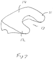
- the area which has been removed is generally rectangular in shape and as shown more clearly in Figure 7 comprises anterior lobes 11, 12 with a space 13 therebetween.
- the posterior region of the prosthesis remains substantially the same as an existing prosthesis upper end plate.
- the lower surface has a lower centre of radius of curvature in accordance with requirements of an earlier designed prosthesis.
- the load displacement characteristics of the standard maverick disc were tested against sawbone material using a roller bearing to allow lateral displacement and to compare the results with at least a machined surface.
- Figure 6 shows a comparison of load displacement graphs of an unmodified prosthesis compared to a modified prosthesis as shown in Figure 5 . From this comparison the following observations can be made.
- an alternative strategy may be to provide an insert plate configured to move the centroid of the combined end plate and insert.
- a lower end plate may be provided with an insert plate to avoid redesigning the lower surface.
- Figures 8A to 8D show one embodiment of the lower end plate which has a central spherical region 20 which couples with an upper end plate having a similarly shaped recess (socket) formed in its lower surface.
- This insert plate would be attached to the adjacent vertebrae.
- the posterior region 16 of the plate 15 would effectively cover the majority of the posterior section of the lower end plate and the anterior region 17 would be provided with side lobes 18 and 19 to effectively build up the sides of the lower end plate.
- the result would be an effective recess being formed between the anterior sides of the lower end plate. This would result in effective movement of the centroid for the lower end plate towards the centre of rotation of curvature of the prosthesis.
- Figures 9A to 9D show an alternative embodiment of a lower end plate 30 which is generally more rectangular in shape than the previous embodiment. Underneath the insert plate a scalloped out region 31 is provided anteriorly with its centre aligned with the centre of the semi-spherical ball portion 32 on its upper surface.
- the scalloped out region 31 commences at a forward most end of the insert and curves concavely rearwardly to the bottom surface more than half of the way along the length of the end plate (measured from front to rear) to a point which is rearward of the centre of the semi-spherical ball portion 32. This effectively moves the centroid rearwardly.
- Figure 9B shows that the scalloped region is part circular in shape.
- the inserts shown in Figures 8A to 9D can be configured to couple with an upper end plate in a similar fashion to that shown in Figures 1 and 2 .
- the lower end of the adjacent vertebrae to the upper end plate may be physically altered so that a recess is provided in an anterior central section to provide a similar effect to that discussed above by providing a recess in the anterior central region of the upper end plate.
Landscapes
- Health & Medical Sciences (AREA)
- Engineering & Computer Science (AREA)
- Biomedical Technology (AREA)
- Orthopedic Medicine & Surgery (AREA)
- Neurology (AREA)
- Heart & Thoracic Surgery (AREA)
- Oral & Maxillofacial Surgery (AREA)
- Transplantation (AREA)
- Cardiology (AREA)
- Vascular Medicine (AREA)
- Life Sciences & Earth Sciences (AREA)
- Animal Behavior & Ethology (AREA)
- General Health & Medical Sciences (AREA)
- Public Health (AREA)
- Veterinary Medicine (AREA)
- Prostheses (AREA)
Description
- The present invention relates to an intervertebral prosthesis for use in a skeletal structure. In one application the invention relates to a prosthesis for use as an artificial invertebral disk, predominantly but not exclusively for use in human spines.
- A human invertebral disk maintains a linkage between adjacent vertebrae of the vertebral column. It must fulfil a number of important functions including load bearing and dampening of impact forces. Furthermore, it must permit a complex pattern of movements and resist various stresses, pure or combined, in the sagittal, coronal and axial planes. Assisted by musco-ligamentous structures surrounding the spine, the invertebral disk must also help to maintain the normal alignment of the vertebrae of the spinal column.
- An ideal artificial disk replacement will accurately reproduce all the functions of the invertebral disk. However although there have been many different artificial disks which have been described and tested, at this time they have all failed to reproduce the abilities of an invertebral disk.
- Typical failings of previous artificial disks have included loosening or dislodgement of vertebral fixation, premature materials wear or structural failure, poor replication of normal or physiological spinal segmental motion and predisposition to the loss of normal neutral vertebral alignment.
- An important aspect of the normal motion of the spinal column and the kinematics of the various invertebral motion segments is the behaviour of the motion segments during flexion and extension movements in the sagittal plane. Fundamental to the kinematics is the location of the instantaneous axis of rotation (IAR). The IAR varies from level to level within the spinal column and throughout flexion and extension movements for any given motion segment (level).
- One type of spinal disk prosthesis is described in
US patent 5674296 . The endoprosthesis described consists of a resilient body having a generally elliptical shape. The endoprosthesis is affixed between adjacent upper and lower vertebrae through L-shaped supports each having confronting concave-convex legs for engaging the adjacent bone sectional thickness on one surface and retaining the resilient endoprosthesis therebetween. The endoprosthesis is centrally located between the upper and lower vertebrae to allow central pivoting of the upper vertebrae relative to the lower vertebrae. - In addition to the above a gasket and seal are located at the anterior and posterior regions between the vertebrae to seal the endoprosthesis in its position between the upper and lower vertebrae.
-
US Patent 5556431 describes another type of invertebral disk endoprosthesis in which top and bottom plates are used instead of the L-shaped supports of the above identified US patent. The endoprosthesis described includes a core which has spherical upper and lower surfaces which from drawings shown appear to be aligned with a central vertical axis through the upper and lower vertebrae. - In contrast to
US 5674296 the prosthesis core of this patent has an edge rim which limits the range of movement of the core and ensures even under extreme conditions cohesion of the prosthesis. - This patent also discloses displacement of the centre of articulation of the prosthesis towards the rear relative to the centre of the vertebral end plates so as to provide sufficient space in the ventral edge area of the prosthesis upper and lower plates so as to enable receipt of bone screws.
- Other artificial prostheses have sought to reproduce normal variation in the location of the IAR using various mechanisms including the use of viscoelastic deformable cores. An example of this is shown in
US Patent No. 5824094 . Unfortunately these type of artificial disks are subject to premature materials wear and stress failure. Furthermore, artificial disks with metallic springs have not yet found their way into clinical use. - All of the artificial disks described above have inherent problems which ultimately create unnatural stresses and resultant pain for an artificial disk implant recipient. The present invention provides an alternative prosthesis which is aimed at mitigating at least some of the problems associated with prior art prosthesis.
- The applicant's co-pending application identified by application number
2005901682 published asWO2006/105603 A1 , is entitled Vertebral Disc Prosthesis - A prosthesis is described in this patent application comprising an upper part for attachment to an upper vertebrae, a lower part for attachment to a lower vertebrae and a middle part located between the upper and lower parts. The centre of the radius of curvature of coacting surfaces of all parts is offset rearwardly with respect to a central vertical axis through the upper and lower vertebrae.
- The upper part which is in the form of an upper end plate typically has an upper surface which is connected to the lower surface of an upper vertebrae. Investigations have revealed that the upper end plate may suffer from subsidence. Typically plate failure occurs by tilting with the posterior aspect of the prosthesis subsiding. The anterior aspect has not been shown to subside. Furthermore, subsidence occurs almost exclusively at the upper posterior corner of the upper plate.
-
US 2003/220691 A1 discloses artificial disc devices to restore correct anatomical intervertebral spacing for damaged discs while maintaining a substantially normal range of biomechanical movement for the vertebrae,US 2005/246022 A1 discloses an artificial intervertebral implant,US-A-5 534 029 discloses an articulated vertebral body spacer, andUS-A-5 314 477 discloses a prosthesis for intervertebral discs. - According to the present invention there is provided an intervertebral prosthesis as defined in
claim 1. - Further embodiments of the invention are described in the dependent claims.
attachment to a skeletal body part. - The prothesis preferably comprises an upper or lower end plate for attachment to a skeletal body part.
- The prosthesis may comprise an insert configured for location between an end plate and a skeletal body part.
- The skeletal body part may be a vertebrae.
- It is preferred that a skeletal body includes any skeletal structure for a biological or mechanical structure.
- It is preferred that a prosthesis refers to any component which is designed to replace part of a skeletal structure, simulate or enhance movement of a skeletal structure.
- The prosthesis may comprise at least two parts including an upper part and lower part which are able to pivot with respect to each other when in use.
- The prosthesis may have a core which is able to pivot and/or translate with respect to the upper and lower parts.
- The upper part may be able to slide (translate with respect to the upper part).
- The upper or lower prosthetic part may comprise an insert.
- The upper or lower prosthetic part preferably comprises an end plate and/or an insert.
- The insert may be configured to build up a relevant portion of an upper surface of an upper part or a lower surface of a lower part.
- The contact surface may comprise an upper surface of the upper part or a lower surface of the lower part.
- A part of the contact surface may be cut out.
- A portion of the contact surface may be removed.
- The the contact surface may be provided with a recessed region.
- Preferably the recessed region is located between opposite sides of the contact surface.
- A portion in front of the centroid may be cut out.
- A recess may be created between opposite sides of an anterior portion of the upper surface.
- Preferably substantially identical side portions are fermed which are separated by a recess.
- The recess may be rectangular in shape.
- The side portions may have substantially parallel edges.
- The side portions may have a generally rectangular cross section.
- The anterior portion may comprise a plurality of recesses or holes.
- It is preferred that according to at least one of the above aspects of the invention that if subsidence is to occur for an upper end plate in a prosthesis, that it occurs without tilting and is parallel subsidence.
- Although it is desirable to configure the contact surface with a centroid substantially at the equivalent location for the centre of rotation of curvature, a reduction in loading failure can be achieved by any movement of the centroid towards the vertical axis which would align with the centre of rotation of curvature of the skeletal part.
- Preferably part of the prosthetic component is removed in a manner which moves the centroid towards a position which is closer to the centre of rotation of curvature.
- It is preferred that.
- A preferred embodiment of the present invention may now be described by way of example only with reference to the accompanying drawings in which:
-
Figure 1 shows a side schematic view of a prosthesis; -
Figure 2 shows the prosthesis shown inFigure 1 with a non-uniform pressure distribution; -
Figure 3 shows a top view of a top plate of a prosthesis according to a preferred embodiment of the present invention; -
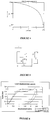
Figure 4 shows a graphical representation of parameter b inFigure 3 versus surface area; -
Figure 5 shows a top view of a proposed cut out for testing that has net moment of zero; -
Figure 6 shows a comparison of load displacement curves for an unmodified prosthesis and a prosthesis as shown inFigure 5 ; -
Figure 7 shows a perspective view of an upper end plate of a prosthesis according to one embodiment of the present invention; -
Figure 8A shows a perspective view of an end plate insert for use with a lower plate prosthesis according to one embodiment of the present invention; -
Figure 8B shows a top view of the end plate insert shown inFigure 8A ; -
Figure 8C shows a front view of the end plate insert shown inFigure 8A ; -
Figure 8D shows an end view of the end plate insert shown inFigure 8A ; -
Figure 9A shows a perspective view of an end plate insert according to a further embodiment of the present invention; -
Figure 9B shows a top view of the end plate insert shown inFigure 9A ; -
Figure 9C shows a front view of the end plate insert shown inFigure 9A ; and -
Figure 9D shows an end view of the end plate insert shown inFigure 9A . - According to a preferred embodiment of the present invention the instant centre of rotation (ICR) needs to be in the posterior portion of the upper end plate of the inferior vertebral body. Failure to achieve this position will prevent normal movement of the prosthesis and facet movement will be abnormal.
- Little attention has so far been given to the statically loaded disc prosthesis - in other words, when it is not moving. This is the position in which the implant finds itself most of the time. In this position the neuromuscular control system recruits whatever muscles are necessary to maintain a static posture.
- In a situation where a person is standing in a static position, the upper and lower end plates are parallel (
Figure 1 ). - If it is assumed that the applied load is distributed evenly across the surface of the implant it will have a uniform pressure distribution. If this were the case with the standard maverick footprint there would be an unbalanced net moment causing the prosthesis to tilt into flexion and subside at the posterior end plate. This can be conceptually thought about by considering a series of small areas of the prosthesis end plate. If the pressure distribution is uniform, the force on these small areas is equal. The moment about the pivot point of the prosthesis however depends on the distance of that small area from the pivot. If all the moments are summed together there will be a net flexion moment. Another way of considering this is that the centre of mass of the current maverick prosthesis is in front of the pivot point, thus causing a net moment. This will make the pressure distribution non uniform. A non uniform pressure distribution would make the prosthesis fail by subsidence into the posterior end plate (
Figure 2 ). - To deal with the above problem the upper end plate has been designed with a sufficient amount of the surface area removed from the front of the prosthesis so that the net moment is nil. This results in a substantially uniform pressure distribution.
-
Figure 3 shows an embodiment of the invention in which the upper surface of the upper end plate has a rectangular "cut out" from the front of a maverick end plate. - As shown the area which has been removed is generally rectangular in shape and as shown more clearly in
Figure 7 comprises anterior lobes 11, 12 with aspace 13 therebetween. The posterior region of the prosthesis remains substantially the same as an existing prosthesis upper end plate. Likewise the lower surface has a lower centre of radius of curvature in accordance with requirements of an earlier designed prosthesis. - For a pure mathematical analysis of the effects of removing surface area from the anterior region of the prosthesis, it is necessary to consider a uniform pressure distribution acting on the entire surface area. At each small area a uniform force will act.
- Referring to first principles a mathematical analysis can be provided for the prosthesis as shown in
Figure 3 on the basis that moments are balanced around the pivot line. - Thus moments acting behind the pivot equal moments acting in front of the pivot.
- The resultant mathematical equation is as follows:

maverick prosthesis equation 1 gives the relationship between c and b that will result in a number of solutions that still will have balanced moments. The total area of contact will vary according to the equation.
- Using a reasonable estimate for parameter 'b' of 7 mm the shape was submitted for engineering subsidence testing against a sawbone foam.
- The centre of mass in the y axis for the above diagram is calculated as 10.6 mm from the posterior edge of the prosthesis using the formula.

- This suggests also that the prosthesis should not tilt when loaded.
- It was theorized also that whilst the yield load should be decreased because of the reduction in surface area that to some extent this would be compensated for by the avoidance of high loading on the posterior edge of the prosthesis due to non uniform pressure distribution. This would be confirmed by a finding of a lower percentage reduction in failure load than would be expected by the reduction in surface area alone.
- Preliminary testing by compressing a maverick disc prosthesis into soft foam suggested that tilting did occur and was associated with a translatatory movement.
- The load displacement characteristics of the standard maverick disc were tested against sawbone material using a roller bearing to allow lateral displacement and to compare the results with at least a machined surface.
- Experimental results revealed the following:
- 1. Under loading conditions that did not allow the upper end plate to flex in relation to the lower end plate the Maverick disc prosthesis collapsed into an attitude of flexion by subsiding into the posterior end plate.
- 2. The anterior edge of the prosthesis did not contact the sawbone and indentation appeared to stop 10 mm in front of the ball (equal to the distance of the ball from the posterior edge) .
- 3. The area of modified cutout prosthesis was 69% of the area of the original maverick prosthesis. While the Yield load was 89% of the original.
- 4. Subsidence by tilting of the unmodified prosthesis was associated with 2 mm of posterior displacement of the lower vertebrae in relation to the fixed upper vertebrae. This would cause extra facet loading.
- 5. The modified cutout prosthesis did not tilt with subsidence and collapsed into the end plate with its end plate parallel to the sawbones end plate. This was accomplished with very little lateral displacement (0.15 mm) .
-
Figure 6 shows a comparison of load displacement graphs of an unmodified prosthesis compared to a modified prosthesis as shown inFigure 5 . From this comparison the following observations can be made. - 1. The peripheral strength and relative weakness of the central portion of the end plate mean that if an anterocentral cutout is made it should cause less reduction in total end plate yield than if the material was uniform. This may enlarge the discrepancy between yield load achieved and that expected by reduction in surface area alone.
- 2. The posterior end plate is stronger than the anterior end plate. The centre of mass of the prosthesis may therefore not need to be exactly at the axis of rotation of the prosthesis and therefore the cutout may need to be less.
- 3. By adding more lateral area near the pivot point the surface area of contact could be increased with little effect on the net moments. A more rounded prosthesis would also have a centre of mass closer to the pivot point. The vertebral end plate is known to be in the shape of a cardioid 2.
- 4. The effect of cyclical loading is not known. It is possible that it is significant with high cyclical loads at the posterior edge of the prosthesis and the effect noted above may be exaggerated.
- Based on the above it is considered that in addition to redesigning the upper surface of the upper end plate an alternative strategy may be to provide an insert plate configured to move the centroid of the combined end plate and insert. According to another embodiment of the invention a lower end plate may be provided with an insert plate to avoid redesigning the lower surface.
-
Figures 8A to 8D show one embodiment of the lower end plate which has a centralspherical region 20 which couples with an upper end plate having a similarly shaped recess (socket) formed in its lower surface. This insert plate would be attached to the adjacent vertebrae. Theposterior region 16 of theplate 15 would effectively cover the majority of the posterior section of the lower end plate and theanterior region 17 would be provided withside lobes -
Figures 9A to 9D show an alternative embodiment of alower end plate 30 which is generally more rectangular in shape than the previous embodiment. Underneath the insert plate a scalloped outregion 31 is provided anteriorly with its centre aligned with the centre of thesemi-spherical ball portion 32 on its upper surface. - As shown in
Figures 9A and 9D the scalloped outregion 31 commences at a forward most end of the insert and curves concavely rearwardly to the bottom surface more than half of the way along the length of the end plate (measured from front to rear) to a point which is rearward of the centre of thesemi-spherical ball portion 32. This effectively moves the centroid rearwardly. -
Figure 9B shows that the scalloped region is part circular in shape. - Thus it can be seen that the embodiment shown in
Figures 9A to 9D uses a scalloped out region to provide a change in the position of the centroid whereas the embodiment shown inFigures 8A to 8D achieves the same or a similar purpose by shaping the insert withside lobes - The inserts shown in
Figures 8A to 9D can be configured to couple with an upper end plate in a similar fashion to that shown inFigures 1 and 2 . As the design of both of the embodiments shown inFigures 8A to 9D result in a change in the position of the centroid of the lower end plate, this can have advantages as outlined previously having regard to the previous experimental results. - According to an alternative embodiment of the invention the lower end of the adjacent vertebrae to the upper end plate may be physically altered so that a recess is provided in an anterior central section to provide a similar effect to that discussed above by providing a recess in the anterior central region of the upper end plate.
- According to alternative aspects of the present invention the same theory relied upon may be applied to the lower end plate of a prosthesis.
- In the claims which follow and in the preceding description of the invention, except where the context requires otherwise due to express language or necessary implication, the word "comprise" or variations such as "comprises" or "comprising" is used in an inclusive sense, i.e. to specify the presence of the stated features but not to preclude the presence or addition of further features in various embodiments of the invention.
Claims (10)
- An intervertebral prosthesis for a vertebral column comprising at least an upper part for attachment to an upper vertebrae and a lower part for attachment to a lower vertebrae, the upper part having a lower curved surface and the lower part having an upper curved surface, wherein in situ the upper and lower curved surfaces have a centre of radius of curvature offset rearwardly with respect to a central vertical axis through the upper and lower vertebrae to which end the centre of radius of curvature is arranged toward the posterior side of the prosthesis, with the centroid of a contact surface of at least one of the upper and lower parts being positioned substantially on the same vertical axis as the centre of the radius of curvature, which contact surface is configured to contact an adjacent vertebrae.
- The prosthesis of claim 1, further including a middle part which is able to pivot and translate with respect to the upper and lower parts.
- The prosthesis of claim 1, the upper part and the lower part being able to pivot with respect to each other when in use.
- The prosthesis as claimed in claim 3, including a core which is able to pivot and/or translate with respect to the upper and lower parts.
- The prosthesis as claimed in claim 3, wherein at least one of the upper and lower prosthetic parts comprises an insert.
- The prosthesis as claimed in claim 3, wherein the contact surface comprises at least one of an upper surface of the upper part and a lower surface of the lower part.
- The prosthesis as claimed in claim 3, wherein a part of the contact surface is cut out.
- The prosthesis as claimed in claim 3, the contact surface being providing with a recessed region.
- The prosthesis as claimed in claim 8, wherein the recessed region is located between opposite sides of an anterior portion of the contact surface.
- The prosthesis as claimed in claim 1, wherein a portion in front of the centroid is cut out.
Applications Claiming Priority (2)
| Application Number | Priority Date | Filing Date | Title |
|---|---|---|---|
| AU2005906204A AU2005906204A0 (en) | 2005-11-04 | A method for reducing loading failure for a prosthetic component | |
| PCT/AU2006/001640 WO2007051247A1 (en) | 2005-11-04 | 2006-11-02 | A method of reducing loading failure for a prosthetic component |
Publications (3)
| Publication Number | Publication Date |
|---|---|
| EP1945148A1 EP1945148A1 (en) | 2008-07-23 |
| EP1945148A4 EP1945148A4 (en) | 2010-03-17 |
| EP1945148B1 true EP1945148B1 (en) | 2019-07-03 |
Family
ID=38005356
Family Applications (1)
| Application Number | Title | Priority Date | Filing Date |
|---|---|---|---|
| EP06804463.5A Not-in-force EP1945148B1 (en) | 2005-11-04 | 2006-11-02 | Intervertebral prosthesis |
Country Status (9)
| Country | Link |
|---|---|
| US (1) | US10045856B2 (en) |
| EP (1) | EP1945148B1 (en) |
| JP (1) | JP2009514568A (en) |
| KR (1) | KR101360188B1 (en) |
| CN (1) | CN101340863B (en) |
| BR (1) | BRPI0618264A2 (en) |
| CA (1) | CA2628236A1 (en) |
| WO (1) | WO2007051247A1 (en) |
| ZA (1) | ZA200804260B (en) |
Families Citing this family (4)
| Publication number | Priority date | Publication date | Assignee | Title |
|---|---|---|---|---|
| US11234838B2 (en) | 2018-09-07 | 2022-02-01 | Additive Implants, Inc. | Dynamic intervertebral spacer implant |
| US10299938B1 (en) | 2018-09-07 | 2019-05-28 | John R. Ehteshami | Dynamic intervertebral spacer implant |
| US11684482B2 (en) | 2018-12-20 | 2023-06-27 | Additive Implants, Inc. | Spondylolisthesis system and methods |
| US11123201B2 (en) | 2019-09-24 | 2021-09-21 | Additive Implants, Inc. | Intervertebral spacer |
Family Cites Families (28)
| Publication number | Priority date | Publication date | Assignee | Title |
|---|---|---|---|---|
| FR2659226B1 (en) * | 1990-03-07 | 1992-05-29 | Jbs Sa | PROSTHESIS FOR INTERVERTEBRAL DISCS AND ITS IMPLEMENTATION INSTRUMENTS. |
| US5258031A (en) * | 1992-01-06 | 1993-11-02 | Danek Medical | Intervertebral disk arthroplasty |
| US5425773A (en) * | 1992-01-06 | 1995-06-20 | Danek Medical, Inc. | Intervertebral disk arthroplasty device |
| JPH06178787A (en) * | 1992-12-14 | 1994-06-28 | Shima Yumiko | Articulated vertebral body spacer, intervertebral space measuring instrument and vertebral body spacer model |
| US5676701A (en) * | 1993-01-14 | 1997-10-14 | Smith & Nephew, Inc. | Low wear artificial spinal disc |
| US5888226A (en) * | 1997-11-12 | 1999-03-30 | Rogozinski; Chaim | Intervertebral prosthetic disc |
| US6679915B1 (en) * | 1998-04-23 | 2004-01-20 | Sdgi Holdings, Inc. | Articulating spinal implant |
| CN2333369Y (en) * | 1998-05-29 | 1999-08-18 | 中山医科大学孙逸仙纪念医院 | Artificial lumbar intervertebral disc |
| DE59904848D1 (en) * | 1999-05-21 | 2003-05-08 | Link Waldemar Gmbh Co | Intervertebral endoprosthesis with a toothed connecting plate |
| AU774503B2 (en) * | 1999-10-19 | 2004-07-01 | Warsaw Orthopedic, Inc. | Spinal implant and cutting tool preparation accessory for mounting the implant |
| US6989032B2 (en) | 2001-07-16 | 2006-01-24 | Spinecore, Inc. | Artificial intervertebral disc |
| WO2003065929A2 (en) * | 2002-02-07 | 2003-08-14 | Ebi, L.P. | Anterior spinal implant |
| US6706068B2 (en) * | 2002-04-23 | 2004-03-16 | Bret A. Ferree | Artificial disc replacements with natural kinematics |
| US7001433B2 (en) | 2002-05-23 | 2006-02-21 | Pioneer Laboratories, Inc. | Artificial intervertebral disc device |
| CA2502292C (en) | 2002-10-31 | 2011-07-26 | Spinal Concepts, Inc. | Movable disc implant |
| GB0301085D0 (en) * | 2003-01-17 | 2003-02-19 | Krishna Manoj | Articulating spinal disc prosthesis |
| US7364589B2 (en) * | 2003-02-12 | 2008-04-29 | Warsaw Orthopedic, Inc. | Mobile bearing articulating disc |
| US7326251B2 (en) * | 2003-04-01 | 2008-02-05 | Sdgi Holdings, Inc. | Interbody fusion device |
| US7621956B2 (en) * | 2003-07-31 | 2009-11-24 | Globus Medical, Inc. | Prosthetic spinal disc replacement |
| US7794465B2 (en) * | 2003-09-10 | 2010-09-14 | Warsaw Orthopedic, Inc. | Artificial spinal discs and associated implantation instruments and methods |
| GB0325421D0 (en) * | 2003-10-30 | 2003-12-03 | Gill Steven S | An intervertebral prosthesis |
| US7670377B2 (en) * | 2003-11-21 | 2010-03-02 | Kyphon Sarl | Laterally insertable artifical vertebral disk replacement implant with curved spacer |
| US20050154462A1 (en) * | 2003-12-02 | 2005-07-14 | St. Francis Medical Technologies, Inc. | Laterally insertable artificial vertebral disk replacement implant with translating pivot point |
| AU2005216112B2 (en) * | 2004-02-20 | 2010-07-08 | Spinecore, Inc. | Artificial intervertebral disc having a universal joint |
| AU2004324223A1 (en) * | 2004-09-08 | 2006-04-27 | Ignacio Abad Rico | Universal intervertebral disc prosthesis |
| US7582115B2 (en) * | 2004-09-30 | 2009-09-01 | Helmut Weber | Intervertebral prosthesis |
| US7566346B2 (en) * | 2004-10-29 | 2009-07-28 | X-Spine Systems, Inc. | Prosthetic implant and method |
| US7887589B2 (en) * | 2004-11-23 | 2011-02-15 | Glenn Bradley J | Minimally invasive spinal disc stabilizer and insertion tool |
-
2006
- 2006-11-02 BR BRPI0618264-0A patent/BRPI0618264A2/en not_active Application Discontinuation
- 2006-11-02 WO PCT/AU2006/001640 patent/WO2007051247A1/en not_active Ceased
- 2006-11-02 KR KR1020087013434A patent/KR101360188B1/en not_active Expired - Fee Related
- 2006-11-02 EP EP06804463.5A patent/EP1945148B1/en not_active Not-in-force
- 2006-11-02 JP JP2008538227A patent/JP2009514568A/en active Pending
- 2006-11-02 CA CA002628236A patent/CA2628236A1/en not_active Abandoned
- 2006-11-02 US US12/084,471 patent/US10045856B2/en active Active
- 2006-11-02 CN CN2006800463789A patent/CN101340863B/en not_active Expired - Fee Related
-
2008
- 2008-05-16 ZA ZA200804260A patent/ZA200804260B/en unknown
Non-Patent Citations (1)
| Title |
|---|
| None * |
Also Published As
| Publication number | Publication date |
|---|---|
| US20100331982A1 (en) | 2010-12-30 |
| JP2009514568A (en) | 2009-04-09 |
| ZA200804260B (en) | 2009-01-28 |
| KR101360188B1 (en) | 2014-02-11 |
| CN101340863A (en) | 2009-01-07 |
| US10045856B2 (en) | 2018-08-14 |
| CN101340863B (en) | 2013-04-03 |
| EP1945148A1 (en) | 2008-07-23 |
| WO2007051247A1 (en) | 2007-05-10 |
| KR20080084934A (en) | 2008-09-22 |
| EP1945148A4 (en) | 2010-03-17 |
| CA2628236A1 (en) | 2007-05-10 |
| BRPI0618264A2 (en) | 2011-08-23 |
Similar Documents
| Publication | Publication Date | Title |
|---|---|---|
| US8556973B2 (en) | Intervertebral disc prosthesis having multiple bearing surfaces | |
| JP4990296B2 (en) | Intervertebral disk replacement device | |
| US7776092B2 (en) | Elastomeric intervertebral disc prosthesis | |
| US10226354B2 (en) | Prosthesis | |
| JP2011518007A (en) | Artificial intervertebral spacer | |
| KR20080064184A (en) | Intervertebral Implants | |
| US20110264223A1 (en) | Self-adjusting and self-stabilizing intervertebral disc prothesis | |
| US10045856B2 (en) | Method of reducing loading failure for a prosthetic component | |
| Rohlmann et al. | Effect of position and height of a mobile core type artificial disc on the biomechanical behaviour of the lumbar spine | |
| AU2014280965B2 (en) | A method of reducing loading failure for a prosthetic component | |
| AU2006308801B2 (en) | A method of reducing loading failure for a prosthetic component | |
| JP2010528788A (en) | Artificial disc | |
| AU2012203631A1 (en) | A method of reducing loading failure for a prosthetic component | |
| MX2008005811A (en) | A method of reducing loading failure for a prosthetic component | |
| AU2006230808A1 (en) | Vertebral disc prosthesis |
Legal Events
| Date | Code | Title | Description |
|---|---|---|---|
| PUAI | Public reference made under article 153(3) epc to a published international application that has entered the european phase |
Free format text: ORIGINAL CODE: 0009012 |
|
| 17P | Request for examination filed |
Effective date: 20080528 |
|
| AK | Designated contracting states |
Kind code of ref document: A1 Designated state(s): AT BE BG CH CY CZ DE DK EE ES FI FR GB GR HU IE IS IT LI LT LU LV MC NL PL PT RO SE SI SK TR |
|
| A4 | Supplementary search report drawn up and despatched |
Effective date: 20100215 |
|
| 17Q | First examination report despatched |
Effective date: 20120405 |
|
| DAX | Request for extension of the european patent (deleted) | ||
| RAP1 | Party data changed (applicant data changed or rights of an application transferred) |
Owner name: NUVASIVE, INC. |
|
| RIN1 | Information on inventor provided before grant (corrected) |
Inventor name: NUVASIVE, INC. |
|
| GRAP | Despatch of communication of intention to grant a patent |
Free format text: ORIGINAL CODE: EPIDOSNIGR1 |
|
| STAA | Information on the status of an ep patent application or granted ep patent |
Free format text: STATUS: GRANT OF PATENT IS INTENDED |
|
| INTG | Intention to grant announced |
Effective date: 20190121 |
|
| RIN1 | Information on inventor provided before grant (corrected) |
Inventor name: MCCOMBE PETER |
|
| GRAS | Grant fee paid |
Free format text: ORIGINAL CODE: EPIDOSNIGR3 |
|
| GRAA | (expected) grant |
Free format text: ORIGINAL CODE: 0009210 |
|
| STAA | Information on the status of an ep patent application or granted ep patent |
Free format text: STATUS: THE PATENT HAS BEEN GRANTED |
|
| AK | Designated contracting states |
Kind code of ref document: B1 Designated state(s): AT BE BG CH CY CZ DE DK EE ES FI FR GB GR HU IE IS IT LI LT LU LV MC NL PL PT RO SE SI SK TR |
|
| REG | Reference to a national code |
Ref country code: GB Ref legal event code: FG4D |
|
| REG | Reference to a national code |
Ref country code: CH Ref legal event code: EP Ref country code: AT Ref legal event code: REF Ref document number: 1150074 Country of ref document: AT Kind code of ref document: T Effective date: 20190715 |
|
| REG | Reference to a national code |
Ref country code: DE Ref legal event code: R096 Ref document number: 602006058260 Country of ref document: DE |
|
| REG | Reference to a national code |
Ref country code: IE Ref legal event code: FG4D |
|
| REG | Reference to a national code |
Ref country code: NL Ref legal event code: MP Effective date: 20190703 |
|
| REG | Reference to a national code |
Ref country code: LT Ref legal event code: MG4D |
|
| REG | Reference to a national code |
Ref country code: AT Ref legal event code: MK05 Ref document number: 1150074 Country of ref document: AT Kind code of ref document: T Effective date: 20190703 |
|
| PG25 | Lapsed in a contracting state [announced via postgrant information from national office to epo] |
Ref country code: CZ Free format text: LAPSE BECAUSE OF FAILURE TO SUBMIT A TRANSLATION OF THE DESCRIPTION OR TO PAY THE FEE WITHIN THE PRESCRIBED TIME-LIMIT Effective date: 20190703 Ref country code: SE Free format text: LAPSE BECAUSE OF FAILURE TO SUBMIT A TRANSLATION OF THE DESCRIPTION OR TO PAY THE FEE WITHIN THE PRESCRIBED TIME-LIMIT Effective date: 20190703 Ref country code: PT Free format text: LAPSE BECAUSE OF FAILURE TO SUBMIT A TRANSLATION OF THE DESCRIPTION OR TO PAY THE FEE WITHIN THE PRESCRIBED TIME-LIMIT Effective date: 20191104 Ref country code: FI Free format text: LAPSE BECAUSE OF FAILURE TO SUBMIT A TRANSLATION OF THE DESCRIPTION OR TO PAY THE FEE WITHIN THE PRESCRIBED TIME-LIMIT Effective date: 20190703 Ref country code: LT Free format text: LAPSE BECAUSE OF FAILURE TO SUBMIT A TRANSLATION OF THE DESCRIPTION OR TO PAY THE FEE WITHIN THE PRESCRIBED TIME-LIMIT Effective date: 20190703 Ref country code: BG Free format text: LAPSE BECAUSE OF FAILURE TO SUBMIT A TRANSLATION OF THE DESCRIPTION OR TO PAY THE FEE WITHIN THE PRESCRIBED TIME-LIMIT Effective date: 20191003 Ref country code: NL Free format text: LAPSE BECAUSE OF FAILURE TO SUBMIT A TRANSLATION OF THE DESCRIPTION OR TO PAY THE FEE WITHIN THE PRESCRIBED TIME-LIMIT Effective date: 20190703 Ref country code: AT Free format text: LAPSE BECAUSE OF FAILURE TO SUBMIT A TRANSLATION OF THE DESCRIPTION OR TO PAY THE FEE WITHIN THE PRESCRIBED TIME-LIMIT Effective date: 20190703 |
|
| PG25 | Lapsed in a contracting state [announced via postgrant information from national office to epo] |
Ref country code: ES Free format text: LAPSE BECAUSE OF FAILURE TO SUBMIT A TRANSLATION OF THE DESCRIPTION OR TO PAY THE FEE WITHIN THE PRESCRIBED TIME-LIMIT Effective date: 20190703 Ref country code: IS Free format text: LAPSE BECAUSE OF FAILURE TO SUBMIT A TRANSLATION OF THE DESCRIPTION OR TO PAY THE FEE WITHIN THE PRESCRIBED TIME-LIMIT Effective date: 20191103 Ref country code: LV Free format text: LAPSE BECAUSE OF FAILURE TO SUBMIT A TRANSLATION OF THE DESCRIPTION OR TO PAY THE FEE WITHIN THE PRESCRIBED TIME-LIMIT Effective date: 20190703 Ref country code: GR Free format text: LAPSE BECAUSE OF FAILURE TO SUBMIT A TRANSLATION OF THE DESCRIPTION OR TO PAY THE FEE WITHIN THE PRESCRIBED TIME-LIMIT Effective date: 20191004 |
|
| PG25 | Lapsed in a contracting state [announced via postgrant information from national office to epo] |
Ref country code: TR Free format text: LAPSE BECAUSE OF FAILURE TO SUBMIT A TRANSLATION OF THE DESCRIPTION OR TO PAY THE FEE WITHIN THE PRESCRIBED TIME-LIMIT Effective date: 20190703 |
|
| PG25 | Lapsed in a contracting state [announced via postgrant information from national office to epo] |
Ref country code: IT Free format text: LAPSE BECAUSE OF FAILURE TO SUBMIT A TRANSLATION OF THE DESCRIPTION OR TO PAY THE FEE WITHIN THE PRESCRIBED TIME-LIMIT Effective date: 20190703 Ref country code: RO Free format text: LAPSE BECAUSE OF FAILURE TO SUBMIT A TRANSLATION OF THE DESCRIPTION OR TO PAY THE FEE WITHIN THE PRESCRIBED TIME-LIMIT Effective date: 20190703 Ref country code: DK Free format text: LAPSE BECAUSE OF FAILURE TO SUBMIT A TRANSLATION OF THE DESCRIPTION OR TO PAY THE FEE WITHIN THE PRESCRIBED TIME-LIMIT Effective date: 20190703 Ref country code: PL Free format text: LAPSE BECAUSE OF FAILURE TO SUBMIT A TRANSLATION OF THE DESCRIPTION OR TO PAY THE FEE WITHIN THE PRESCRIBED TIME-LIMIT Effective date: 20190703 Ref country code: EE Free format text: LAPSE BECAUSE OF FAILURE TO SUBMIT A TRANSLATION OF THE DESCRIPTION OR TO PAY THE FEE WITHIN THE PRESCRIBED TIME-LIMIT Effective date: 20190703 |
|
| PG25 | Lapsed in a contracting state [announced via postgrant information from national office to epo] |
Ref country code: IS Free format text: LAPSE BECAUSE OF FAILURE TO SUBMIT A TRANSLATION OF THE DESCRIPTION OR TO PAY THE FEE WITHIN THE PRESCRIBED TIME-LIMIT Effective date: 20200224 Ref country code: SK Free format text: LAPSE BECAUSE OF FAILURE TO SUBMIT A TRANSLATION OF THE DESCRIPTION OR TO PAY THE FEE WITHIN THE PRESCRIBED TIME-LIMIT Effective date: 20190703 |
|
| REG | Reference to a national code |
Ref country code: DE Ref legal event code: R097 Ref document number: 602006058260 Country of ref document: DE |
|
| REG | Reference to a national code |
Ref country code: CH Ref legal event code: PL |
|
| PLBE | No opposition filed within time limit |
Free format text: ORIGINAL CODE: 0009261 |
|
| STAA | Information on the status of an ep patent application or granted ep patent |
Free format text: STATUS: NO OPPOSITION FILED WITHIN TIME LIMIT |
|
| PG2D | Information on lapse in contracting state deleted |
Ref country code: IS |
|
| PG25 | Lapsed in a contracting state [announced via postgrant information from national office to epo] |
Ref country code: CH Free format text: LAPSE BECAUSE OF NON-PAYMENT OF DUE FEES Effective date: 20191130 Ref country code: MC Free format text: LAPSE BECAUSE OF FAILURE TO SUBMIT A TRANSLATION OF THE DESCRIPTION OR TO PAY THE FEE WITHIN THE PRESCRIBED TIME-LIMIT Effective date: 20190703 Ref country code: LU Free format text: LAPSE BECAUSE OF NON-PAYMENT OF DUE FEES Effective date: 20191102 Ref country code: LI Free format text: LAPSE BECAUSE OF NON-PAYMENT OF DUE FEES Effective date: 20191130 |
|
| 26N | No opposition filed |
Effective date: 20200603 |
|
| REG | Reference to a national code |
Ref country code: BE Ref legal event code: MM Effective date: 20191130 |
|
| PG25 | Lapsed in a contracting state [announced via postgrant information from national office to epo] |
Ref country code: SI Free format text: LAPSE BECAUSE OF FAILURE TO SUBMIT A TRANSLATION OF THE DESCRIPTION OR TO PAY THE FEE WITHIN THE PRESCRIBED TIME-LIMIT Effective date: 20190703 |
|
| PG25 | Lapsed in a contracting state [announced via postgrant information from national office to epo] |
Ref country code: IE Free format text: LAPSE BECAUSE OF NON-PAYMENT OF DUE FEES Effective date: 20191102 Ref country code: FR Free format text: LAPSE BECAUSE OF NON-PAYMENT OF DUE FEES Effective date: 20191130 |
|
| PG25 | Lapsed in a contracting state [announced via postgrant information from national office to epo] |
Ref country code: BE Free format text: LAPSE BECAUSE OF NON-PAYMENT OF DUE FEES Effective date: 20191130 |
|
| PG25 | Lapsed in a contracting state [announced via postgrant information from national office to epo] |
Ref country code: CY Free format text: LAPSE BECAUSE OF FAILURE TO SUBMIT A TRANSLATION OF THE DESCRIPTION OR TO PAY THE FEE WITHIN THE PRESCRIBED TIME-LIMIT Effective date: 20190703 |
|
| PG25 | Lapsed in a contracting state [announced via postgrant information from national office to epo] |
Ref country code: HU Free format text: LAPSE BECAUSE OF FAILURE TO SUBMIT A TRANSLATION OF THE DESCRIPTION OR TO PAY THE FEE WITHIN THE PRESCRIBED TIME-LIMIT; INVALID AB INITIO Effective date: 20061102 |
|
| PGFP | Annual fee paid to national office [announced via postgrant information from national office to epo] |
Ref country code: DE Payment date: 20230428 Year of fee payment: 17 |
|
| PGFP | Annual fee paid to national office [announced via postgrant information from national office to epo] |
Ref country code: GB Payment date: 20230428 Year of fee payment: 17 |
|
| REG | Reference to a national code |
Ref country code: DE Ref legal event code: R119 Ref document number: 602006058260 Country of ref document: DE |
|
| GBPC | Gb: european patent ceased through non-payment of renewal fee |
Effective date: 20231102 |
|
| PG25 | Lapsed in a contracting state [announced via postgrant information from national office to epo] |
Ref country code: DE Free format text: LAPSE BECAUSE OF NON-PAYMENT OF DUE FEES Effective date: 20240601 |
|
| PG25 | Lapsed in a contracting state [announced via postgrant information from national office to epo] |
Ref country code: GB Free format text: LAPSE BECAUSE OF NON-PAYMENT OF DUE FEES Effective date: 20231102 |
|
| PG25 | Lapsed in a contracting state [announced via postgrant information from national office to epo] |
Ref country code: GB Free format text: LAPSE BECAUSE OF NON-PAYMENT OF DUE FEES Effective date: 20231102 Ref country code: DE Free format text: LAPSE BECAUSE OF NON-PAYMENT OF DUE FEES Effective date: 20240601 |