EP1945015A2 - Combination assembly of a LED and a liquid-vapor thermally dissipating device - Google Patents
Combination assembly of a LED and a liquid-vapor thermally dissipating device Download PDFInfo
- Publication number
- EP1945015A2 EP1945015A2 EP07008868A EP07008868A EP1945015A2 EP 1945015 A2 EP1945015 A2 EP 1945015A2 EP 07008868 A EP07008868 A EP 07008868A EP 07008868 A EP07008868 A EP 07008868A EP 1945015 A2 EP1945015 A2 EP 1945015A2
- Authority
- EP
- European Patent Office
- Prior art keywords
- liquid
- led
- dissipating device
- thermally dissipating
- vapor thermally
- Prior art date
- Legal status (The legal status is an assumption and is not a legal conclusion. Google has not performed a legal analysis and makes no representation as to the accuracy of the status listed.)
- Withdrawn
Links
Images





Classifications
-
- H—ELECTRICITY
- H10—SEMICONDUCTOR DEVICES; ELECTRIC SOLID-STATE DEVICES NOT OTHERWISE PROVIDED FOR
- H10H—INORGANIC LIGHT-EMITTING SEMICONDUCTOR DEVICES HAVING POTENTIAL BARRIERS
- H10H20/00—Individual inorganic light-emitting semiconductor devices having potential barriers, e.g. light-emitting diodes [LED]
- H10H20/80—Constructional details
- H10H20/85—Packages
- H10H20/858—Means for heat extraction or cooling
- H10H20/8586—Means for heat extraction or cooling comprising fluids, e.g. heat-pipes
-
- F—MECHANICAL ENGINEERING; LIGHTING; HEATING; WEAPONS; BLASTING
- F21—LIGHTING
- F21V—FUNCTIONAL FEATURES OR DETAILS OF LIGHTING DEVICES OR SYSTEMS THEREOF; STRUCTURAL COMBINATIONS OF LIGHTING DEVICES WITH OTHER ARTICLES, NOT OTHERWISE PROVIDED FOR
- F21V29/00—Protecting lighting devices from thermal damage; Cooling or heating arrangements specially adapted for lighting devices or systems
- F21V29/50—Cooling arrangements
- F21V29/51—Cooling arrangements using condensation or evaporation of a fluid, e.g. heat pipes
-
- H—ELECTRICITY
- H10—SEMICONDUCTOR DEVICES; ELECTRIC SOLID-STATE DEVICES NOT OTHERWISE PROVIDED FOR
- H10W—GENERIC PACKAGES, INTERCONNECTIONS, CONNECTORS OR OTHER CONSTRUCTIONAL DETAILS OF DEVICES COVERED BY CLASS H10
- H10W72/00—Interconnections or connectors in packages
- H10W72/071—Connecting or disconnecting
- H10W72/075—Connecting or disconnecting of bond wires
- H10W72/07551—Connecting or disconnecting of bond wires characterised by changes in properties of the bond wires during the connecting
- H10W72/07554—Connecting or disconnecting of bond wires characterised by changes in properties of the bond wires during the connecting changes in dispositions
-
- H—ELECTRICITY
- H10—SEMICONDUCTOR DEVICES; ELECTRIC SOLID-STATE DEVICES NOT OTHERWISE PROVIDED FOR
- H10W—GENERIC PACKAGES, INTERCONNECTIONS, CONNECTORS OR OTHER CONSTRUCTIONAL DETAILS OF DEVICES COVERED BY CLASS H10
- H10W72/00—Interconnections or connectors in packages
- H10W72/50—Bond wires
- H10W72/541—Dispositions of bond wires
- H10W72/547—Dispositions of multiple bond wires
Definitions
- the present invention relates generally to a light emitting diode (LED), and more particularly to a combination assembly of LED and liquid-vapor thermally dissipating device, which has a greater performance in heat transmission.
- LED light emitting diode
- the high luminance LED produces high temperature, and there is no fine solution to fix it yet.
- U.S. Patent no. 5,173,839 provides a heat transmission technique of a LED display. It provides a stack of a belt, an aluminum block, a belt and a heat sink under a LED chip to transmit the heat out. However, this technique provides three intermediates between the LED chip and the heat sink, which is the one performing heat transmission, that make the heat transmission rate is poor because the intermediates cause a greater heat resistance.
- Taiwan Patent no. M295889 provides another heat transmission technique of LED. It provides a LED on a heat pipe.
- the LED includes a LED plastic insulating circuit board, a LED chip base, a LED heat chip and a LED lens.
- this technique provides the heat pipe, which has a high efficiency of heat transmission, to be the main for heat transmission, but there are also intermediates, the LED chip base and the LED plastic insulating circuit board, therebetween. These intermediates also cause the problem of high heat resistance and low heat transmission rate.
- the primary objective of the present invention is to provide a combination assembly of LED and liquid-vapor thermally dissipating device, which has a greater heat transmission performance for the LED.
- a combination assembly of LED and liquid-vapor thermally dissipating device includes a liquid-vapor thermally dissipating device, a circuit board and at least one LED unit.
- the liquid-vapor thermally dissipating device includes a metal shell with liquid and capillarity structures therein.
- the circuit board is provided on the liquid-vapor thermally dissipating device.
- the LED unit includes a heat transmission base provided on the metal shell of the liquid-vapor thermally dissipating device, a LED chip provided on the heat transmission base, a package device encapsulating the LED chip and two transmitting plates having ends electrically connected to the LED chip and ends exposed out of the package device and electrically connected to the circuit board.
- the heat of the LED unit may be transmitted to the heat sink directly for heat transmission.
- the present invention provides a greater heat transmission efficiency.
- a combination assembly of LED and liquid-vapor thermally dissipating device 10 of the first preferred embodiment of the present invention mainly includes a liquid-vapor thermally dissipating device 11, a circuit board 19 and a plurality of LED units 21.
- the liquid-vapor thermally dissipating device 11 includes a metal shell 12, which is a copper heat pipe in the present embodiment, liquid 14 in the metal shell 12 and a capillarity structure 16.
- the liquid-vapor thermally dissipating device 11 is a heat pipe in the present embodiment.
- the circuit board 19, which is mounted on the liquid-vapor thermally dissipating device 11, has a plurality of bores 191 arranged in series.
- the LED units 21, which are received in the bores 191 respectively, includes a heat transmission base 22, a LED chip 23, a package device 24, two transmitting plates 25, an insulating frame 26 and two wires 27.
- the LED chip 23 includes two electrode plates 231 at a top thereof and an insulating player 232 at a bottom thereof.
- the LED chip 23 has the insulating player 232 mounted on the heat transmission base 22.
- the heat transmission base 22, which has a high heat transmission efficiency, is mounted on the metal shell 12.
- the insulating frame 26 is an annular member surrounding the heat transmission base 22.
- the transmitting plates 25 have ends connected to the insulating frame 26.
- the wires 27 connect the electrodes plates 231 of the LED chip 23 and the transmitting plates 25 that the transmitting plates 25 are electrically connected to the electrode plates 231 of the LED chip 23.
- the package device 24 includes a lid 241 and a ring 242 in the present embodiment.
- the lid 241 is - connected to the ring 242 and the ring 242 is connected to the insulating frame 26.
- the LED chip 23 and the wires are between the package device 24 and the insulating frame 26, and the package device 24 encapsulates parts of the insulating frame 26 and the transmitting plates 25.
- the transmitting plates 25 have end exposed out of the package device 24 and electrically connected to the circuit board 19.
- an electronic driving device (not shown) is connected to the circuit board 19 to provide electricity to the LED chips 23 of the LED units 21 through the transmitting plates 25 to light the LED chips 23.
- the heat generated by the lighting LED chips 23 is transmitted to the metal shell 12 through the heat transmission base 22 to transmit the heat out by the liquid-vapor thermally dissipating device 11. Because of the high heat transmission efficiency of the liquid-vapor thermally dissipating device 11 and the heat transmission base 22, the heat of the lighting LED chips 23 is transmitted out quickly that provides the LED chip having a great heat transmission performance.
- an encapsulant 24' which is transparent or semi-transparent doped with fluorescence powder, encapsulating a top of the insulating frame 26, the wires 27 and the LED chip 23. It has the same function as the lid above.
- a combination assembly of LED and liquid-vapor thermally dissipating device 30 of the second preferred embodiment of the present invention which is similar to the assembly 10 of the first embodiment, except that:
- a combination assembly of LED and liquid-vapor thermally dissipating device 50 of the third preferred embodiment of the present invention which is similar to the assembly 10 of the first embodiment, except that:
- a circuit board 59 is on the flat surface 511, which has a plurality of bores 591 arranged in matrix. A plurality of LED units 61 are received in the bores 591 respectively.
- the third embodiment provides the LED units 61 in matrix, and the rest structure, operation mode and functions are as same as the first embodiment, and we will not describe it again.
- a combination assembly of LED and liquid-vapor thermally dissipating device 70 of the fourth preferred embodiment of the present invention which is similar to the assembly 10 of the first embodiment, except that:
- the heat generated by lighting LED units 81 is transmitted to the heat sink 711 through the liquid-vapor thermally dissipating device 71 for heat transmission by a greater size of the heat sink 711.
Landscapes
- Engineering & Computer Science (AREA)
- General Engineering & Computer Science (AREA)
- Led Device Packages (AREA)
- Cooling Or The Like Of Semiconductors Or Solid State Devices (AREA)
- Devices For Indicating Variable Information By Combining Individual Elements (AREA)
- Electroluminescent Light Sources (AREA)
Abstract
Description
- The present invention relates generally to a light emitting diode (LED), and more particularly to a combination assembly of LED and liquid-vapor thermally dissipating device, which has a greater performance in heat transmission.
- In present days, the high luminance LED produces high temperature, and there is no fine solution to fix it yet.
-
U.S. Patent no. 5,173,839 provides a heat transmission technique of a LED display. It provides a stack of a belt, an aluminum block, a belt and a heat sink under a LED chip to transmit the heat out. However, this technique provides three intermediates between the LED chip and the heat sink, which is the one performing heat transmission, that make the heat transmission rate is poor because the intermediates cause a greater heat resistance. -
Taiwan Patent no. M295889 - The primary objective of the present invention is to provide a combination assembly of LED and liquid-vapor thermally dissipating device, which has a greater heat transmission performance for the LED.
- According to the objective of the present invention, a combination assembly of LED and liquid-vapor thermally dissipating device includes a liquid-vapor thermally dissipating device, a circuit board and at least one LED unit. The liquid-vapor thermally dissipating device includes a metal shell with liquid and capillarity structures therein. The circuit board is provided on the liquid-vapor thermally dissipating device. The LED unit includes a heat transmission base provided on the metal shell of the liquid-vapor thermally dissipating device, a LED chip provided on the heat transmission base, a package device encapsulating the LED chip and two transmitting plates having ends electrically connected to the LED chip and ends exposed out of the package device and electrically connected to the circuit board.
- The heat of the LED unit may be transmitted to the heat sink directly for heat transmission. The present invention provides a greater heat transmission efficiency.
-
-
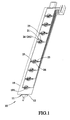
FIG 1 is a perspective view of a first preferred embodiment of the present invention; -
FIG 2 is a top view of the first preferred embodiment of the present invention; -
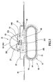
FIG 3 is a sectional view along the 3-3 line ofFIG 2 ; -
FIG 4 is a sectional view of the first preferred embodiment of the present invention, showing another package device; -
FIG 5 is a perspective view of a second preferred embodiment of the present invention; -
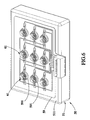
FIG 6 is a perspective view of a third preferred embodiment of the present invention; -
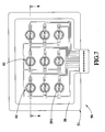
FIG 7 is a top view of the third preferred embodiment of the present invention; -
FIG 8 is a sectional view along the 8-8 line ofFIG. 7 ; and -
FIG. 9 is a perspective view of a fourth preferred embodiment of the present invention. - As shown in
FIG 1 to FIG 3 , a combination assembly of LED and liquid-vapor thermally dissipatingdevice 10 of the first preferred embodiment of the present invention mainly includes a liquid-vapor thermallydissipating device 11, acircuit board 19 and a plurality ofLED units 21. - The liquid-vapor thermally dissipating
device 11 includes ametal shell 12, which is a copper heat pipe in the present embodiment,liquid 14 in themetal shell 12 and acapillarity structure 16. The liquid-vapor thermally dissipatingdevice 11 is a heat pipe in the present embodiment. - The
circuit board 19, which is mounted on the liquid-vapor thermally dissipatingdevice 11, has a plurality ofbores 191 arranged in series. - The
LED units 21, which are received in thebores 191 respectively, includes aheat transmission base 22, aLED chip 23, apackage device 24, twotransmitting plates 25, aninsulating frame 26 and twowires 27. TheLED chip 23 includes twoelectrode plates 231 at a top thereof and aninsulating player 232 at a bottom thereof. TheLED chip 23 has the insulatingplayer 232 mounted on theheat transmission base 22. Theheat transmission base 22, which has a high heat transmission efficiency, is mounted on themetal shell 12. Theinsulating frame 26 is an annular member surrounding theheat transmission base 22. The transmittingplates 25 have ends connected to the insulatingframe 26. Thewires 27 connect theelectrodes plates 231 of theLED chip 23 and thetransmitting plates 25 that thetransmitting plates 25 are electrically connected to theelectrode plates 231 of theLED chip 23. Thepackage device 24 includes alid 241 and aring 242 in the present embodiment. Thelid 241 is - connected to thering 242 and thering 242 is connected to theinsulating frame 26. TheLED chip 23 and the wires are between thepackage device 24 and theinsulating frame 26, and thepackage device 24 encapsulates parts of theinsulating frame 26 and thetransmitting plates 25. Thetransmitting plates 25 have end exposed out of thepackage device 24 and electrically connected to thecircuit board 19. - In operation of the first embodiment, an electronic driving device (not shown) is connected to the
circuit board 19 to provide electricity to theLED chips 23 of theLED units 21 through thetransmitting plates 25 to light theLED chips 23. The heat generated by thelighting LED chips 23 is transmitted to themetal shell 12 through theheat transmission base 22 to transmit the heat out by the liquid-vapor thermally dissipatingdevice 11. Because of the high heat transmission efficiency of the liquid-vapor thermally dissipatingdevice 11 and theheat transmission base 22, the heat of thelighting LED chips 23 is transmitted out quickly that provides the LED chip having a great heat transmission performance. - As shown in
FIG. 4 , an encapsulant 24', which is transparent or semi-transparent doped with fluorescence powder, encapsulating a top of theinsulating frame 26, thewires 27 and theLED chip 23. It has the same function as the lid above. As shown inFIG. 5 , a combination assembly of LED and liquid-vapor thermally dissipatingdevice 30 of the second preferred embodiment of the present invention, which is similar to theassembly 10 of the first embodiment, except that: - A liquid-vapor thermally dissipating
device 31 has anend face 311, on which aLED unit 41 is provided to fit thecircuit board 39. - Electricity supplied to the
transmitting plates 45 of theLED units 41 tolight LED chips 43, and the liquid-vapor thermally dissipatingdevice 31 transfers the heat of thelighting LED chips 43 of theLED units 41 out. - The operation mode and functions of the second embodiment are as same as the first embodiment, and we will not describe it again.
- As shown in
FIG 6 to FIG 8 , a combination assembly of LED and liquid-vapor thermally dissipatingdevice 50 of the third preferred embodiment of the present invention, which is similar to theassembly 10 of the first embodiment, except that: - A liquid-vapor thermally dissipating
device 51 has aflat surface 511. - A
circuit board 59 is on theflat surface 511, which has a plurality ofbores 591 arranged in matrix. A plurality ofLED units 61 are received in thebores 591 respectively. - The main difference is that the third embodiment provides the
LED units 61 in matrix, and the rest structure, operation mode and functions are as same as the first embodiment, and we will not describe it again. - As shown in
FIG 9 , a combination assembly of LED and liquid-vapor thermally dissipatingdevice 70 of the fourth preferred embodiment of the present invention, which is similar to theassembly 10 of the first embodiment, except that: - A liquid-vapor thermally dissipating
device 71 is connected to aheat sink 89. - As a result, the heat generated by
lighting LED units 81 is transmitted to the heat sink 711 through the liquid-vapor thermally dissipatingdevice 71 for heat transmission by a greater size of the heat sink 711. - The operation mode and functions of the second embodiment are as same as the first embodiment, and we will not describe it again.
- In conclusion, the advantages of the present invention are:
- Higher performance of heat transmission: to compare with the prior art, the present invention has no intermediate between the LED chips and the liquid-vapor thermally dissipating device, so that the present invention has less heat transmission resistance. The present invention provides the LED chips mounted on the liquid-vapor thermally dissipating device directly so that the heat of the LED chips may be transmitted to the liquid-vapor thermally dissipating device directly for heat transmission that has a greater performance of heat transmission than the prior art.
- The description above is a few preferred embodiments of the present invention and the equivalence of the present invention is still in the scope of the claim of the present invention.
Claims (11)
- A combination assembly of LED and liquid-vapor thermally dissipating device (10), comprising:a liquid-vapor thermally dissipating device (11) including a metal shell (12) with liquid and capillarity structures (16) therein;a circuit board (19) provided on the liquid-vapor thermally dissipating device (11); andat least one LED unit (21) including a heat transmission base (22) provided on the metal shell (12) of the liquid-vapor thermally dissipating device (11), a LED chip (23) provided on the heat transmission base (22), a package device (24) encapsulating the LED chip (23) and two transmitting plates (25) having ends electrically connected to the LED chip (23) and ends exposed out of the package device (24) and electrically connected to the circuit board (19).
- The combination assembly of LED and liquid-vapor thermally dissipating device (10) as defined in claim 1, wherein the LED unit (21) further includes an insulating frame (26), to which the transmitting plates (25) are connected, surrounding the heat transmission base (22) and two wires (27) connecting the LED chip (23) and the transmitting plates (25).
- The combination assembly of LED and liquid-vapor thermally dissipating device (10) as defined in claim 2, wherein the LED chip (23) has two electrode plates (231) on a top thereof and an insulating layer (232) on a bottom thereof to be mounted on the heat transmission base (22), and the wires (27) have ends connected to one of the electrode plates (231) and one of the transmitting plates (25) respectively, and the package device (24) partially encapsulates the insulating frame (26) and the transmitting plates (25).
- The combination assembly of LED and liquid-vapor thermally dissipating device (10) as defined in claim 2, wherein the package device (24) has a lid (241) provided to the insulating frame (26), and the LED chip (23) and the wires (27) are between the package device (24) and the insulating frame (26).
- The combination assembly of LED and liquid-vapor thermally dissipating device (10) as defined in claim 2, wherein the package device (24) is an encapsulant (24') encapsulating a top of the insulating frame (26), the wires (27) and the LED chip (23).
- The combination assembly of LED and liquid-vapor thermally dissipating device (10) as defined in claim 1, wherein the liquid-vapor thermally dissipating device (11) is a heat pipe.
- The combination assembly of LED and liquid-vapor thermally dissipating device (50) as defined in claim 6, wherein the circuit board (59) has a plurality of bores (591) arranged in series, and there are a plurality of LED units (61) received in the bores (591) respectively.
- The combination assembly of LED and liquid-vapor thermally dissipating device (30) as defined in claim 6, wherein the liquid-vapor thermally dissipating device (31) has an end face (311), on which the circuit board (39) and the LED unit (41) are provided.
- The combination assembly of LED and liquid-vapor thermally dissipating device (50) as defined in claim 1, wherein the liquid-vapor thermally dissipating device (51) has a flat surface (511).
- The combination assembly of LED and liquid-vapor thermally dissipating device (50) as defined in claim 9, wherein the circuit board (59), which has a plurality of bores (591) arranged in matrix, is on the flat surface (511) and there are a plurality of the LED units (61) received in the bores (591).
- The combination assembly of LED and liquid-vapor thermally dissipating device (70) as defined in claim 1, wherein the liquid-vapor thermally dissipating device (71) is connected to a heat sink (89).
Applications Claiming Priority (1)
| Application Number | Priority Date | Filing Date | Title |
|---|---|---|---|
| CNA2007100037190A CN101222007A (en) | 2007-01-12 | 2007-01-12 | Luminous diode with radiator |
Publications (2)
| Publication Number | Publication Date |
|---|---|
| EP1945015A2 true EP1945015A2 (en) | 2008-07-16 |
| EP1945015A3 EP1945015A3 (en) | 2009-12-09 |
Family
ID=39364045
Family Applications (1)
| Application Number | Title | Priority Date | Filing Date |
|---|---|---|---|
| EP07008868A Withdrawn EP1945015A3 (en) | 2007-01-12 | 2007-05-02 | Combination assembly of a LED and a liquid-vapor thermally dissipating device |
Country Status (2)
| Country | Link |
|---|---|
| EP (1) | EP1945015A3 (en) |
| CN (1) | CN101222007A (en) |
Cited By (1)
| Publication number | Priority date | Publication date | Assignee | Title |
|---|---|---|---|---|
| DE102010025315A1 (en) * | 2010-06-28 | 2011-12-29 | Lukas Biberacher | Electronic component |
Families Citing this family (7)
| Publication number | Priority date | Publication date | Assignee | Title |
|---|---|---|---|---|
| JP2012523678A (en) * | 2009-04-10 | 2012-10-04 | 佛山市国星光電股▲ふん▼有限公司 | Power LED heat dissipation substrate, method for manufacturing power LED product, and product by the method |
| CN101566332B (en) * | 2009-05-22 | 2011-09-28 | 大连金三维科技有限公司 | Heat dissipation device and lighting equipment |
| CN102403442A (en) * | 2010-09-07 | 2012-04-04 | 威晶半导体股份有限公司 | Heat conducting structure of light emitting diode |
| CN201820758U (en) * | 2010-09-15 | 2011-05-04 | 杨东佐 | LED integrated structure with cooling device |
| CN102612261A (en) * | 2011-11-20 | 2012-07-25 | 葛豫卿 | High-heat conduction metal core printed circuit board and preparation method for high-heat conduction metal core printed circuit board |
| CN102497726A (en) * | 2011-11-27 | 2012-06-13 | 葛豫卿 | Printed circuit board with liquid-vapor phase transition heat transfer substrate and preparation method thereof |
| CN104676320B (en) * | 2015-01-13 | 2017-02-01 | 中国科学院半导体研究所 | Flexible light-emitting device array and manufacture method thereof |
Family Cites Families (10)
| Publication number | Priority date | Publication date | Assignee | Title |
|---|---|---|---|---|
| DE3146504A1 (en) * | 1981-11-24 | 1983-06-01 | Siemens AG, 1000 Berlin und 8000 München | COOLING CONCEPT FOR MODULES WITH HIGH LOSS PERFORMANCE |
| US4995451A (en) * | 1989-12-29 | 1991-02-26 | Digital Equipment Corporation | Evaporator having etched fiber nucleation sites and method of fabricating same |
| US5353192A (en) * | 1993-02-08 | 1994-10-04 | At&T Bell Laboratories | Circuit card assembly |
| US5936353A (en) * | 1996-04-03 | 1999-08-10 | Pressco Technology Inc. | High-density solid-state lighting array for machine vision applications |
| JPH1022552A (en) * | 1996-07-04 | 1998-01-23 | Mitsubishi Electric Corp | Solid-state laser device and its light source |
| JPH1120234A (en) * | 1997-06-30 | 1999-01-26 | Kyocera Corp | Optical printer head |
| US7095110B2 (en) * | 2004-05-21 | 2006-08-22 | Gelcore, Llc | Light emitting diode apparatuses with heat pipes for thermal management |
| EP1523041A1 (en) * | 2004-12-08 | 2005-04-13 | Jeffrey Chen | Light emitting diode assembly having high-performance heat dissipation means |
| US7270446B2 (en) * | 2005-05-09 | 2007-09-18 | Lighthouse Technology Co., Ltd | Light module with combined heat transferring plate and heat transferring pipes |
| CN100464411C (en) * | 2005-10-20 | 2009-02-25 | 富准精密工业(深圳)有限公司 | Light-emitting diode packaging structure and packaging method |
-
2007
- 2007-01-12 CN CNA2007100037190A patent/CN101222007A/en active Pending
- 2007-05-02 EP EP07008868A patent/EP1945015A3/en not_active Withdrawn
Cited By (2)
| Publication number | Priority date | Publication date | Assignee | Title |
|---|---|---|---|---|
| DE102010025315A1 (en) * | 2010-06-28 | 2011-12-29 | Lukas Biberacher | Electronic component |
| EP2400822A3 (en) * | 2010-06-28 | 2013-04-24 | Spyrelight Gmbh | Electronic component |
Also Published As
| Publication number | Publication date |
|---|---|
| CN101222007A (en) | 2008-07-16 |
| EP1945015A3 (en) | 2009-12-09 |
Similar Documents
| Publication | Publication Date | Title |
|---|---|---|
| US20080170371A1 (en) | Combination assembly of led and heat sink | |
| US20080170367A1 (en) | Combination assembly of LED and liquid-vapor thermally dissipating device | |
| US7919789B2 (en) | Lateral light-emitting diode backlight module | |
| US20080169742A1 (en) | Combination assembly of LED and Liquid-vapor thermally dissipating device | |
| KR20200081350A (en) | Light emitting element, illumination device and foundation thereof | |
| US7611263B2 (en) | Light source module with a thermoelectric cooler | |
| US8002443B2 (en) | LED array module | |
| US7538356B2 (en) | Combination assembly of LED and liquid-vapor thermally dissipating device | |
| JP3132536U (en) | LED module | |
| US7441926B2 (en) | Light emitting diode package | |
| TWI322915B (en) | Heat dissipation structure of backliht module | |
| US20050161682A1 (en) | Light emitting diodes packaged for high temperature operation | |
| US20100270565A1 (en) | Semiconductor light-emitting device and method of fabricating the same | |
| EP1605525A3 (en) | High power LED package | |
| JP2005158957A (en) | Light emitting device | |
| JP6427313B2 (en) | Light emitting device | |
| US7939919B2 (en) | LED-packaging arrangement and light bar employing the same | |
| CN102563452A (en) | Backlight assembly having light emitting diode package and display apparatus having the same | |
| TWM498387U (en) | Thermoelectrically separated LED package module and electrical connection module | |
| US20070246726A1 (en) | Package structure of light emitting device | |
| EP1945009A2 (en) | Combination assembly of led and liquid-vapor thermally dissipating device | |
| EP1945015A3 (en) | Combination assembly of a LED and a liquid-vapor thermally dissipating device | |
| US20100044727A1 (en) | Led package structure | |
| US6838702B1 (en) | Light emitting diode | |
| US7586126B2 (en) | Light emitting diode lighting module with improved heat dissipation structure |
Legal Events
| Date | Code | Title | Description |
|---|---|---|---|
| PUAI | Public reference made under article 153(3) epc to a published international application that has entered the european phase |
Free format text: ORIGINAL CODE: 0009012 |
|
| 17P | Request for examination filed |
Effective date: 20070502 |
|
| AK | Designated contracting states |
Kind code of ref document: A2 Designated state(s): AT BE BG CH CY CZ DE DK EE ES FI FR GB GR HU IE IS IT LI LT LU LV MC MT NL PL PT RO SE SI SK TR |
|
| AX | Request for extension of the european patent |
Extension state: AL BA HR MK RS |
|
| PUAL | Search report despatched |
Free format text: ORIGINAL CODE: 0009013 |
|
| AK | Designated contracting states |
Kind code of ref document: A3 Designated state(s): AT BE BG CH CY CZ DE DK EE ES FI FR GB GR HU IE IS IT LI LT LU LV MC MT NL PL PT RO SE SI SK TR |
|
| AX | Request for extension of the european patent |
Extension state: AL BA HR MK RS |
|
| STAA | Information on the status of an ep patent application or granted ep patent |
Free format text: STATUS: THE APPLICATION HAS BEEN WITHDRAWN |
|
| 18W | Application withdrawn |
Effective date: 20100602 |