EP1945007A1 - Performance optimisation method of LED lighting devices - Google Patents
Performance optimisation method of LED lighting devices Download PDFInfo
- Publication number
- EP1945007A1 EP1945007A1 EP07100432A EP07100432A EP1945007A1 EP 1945007 A1 EP1945007 A1 EP 1945007A1 EP 07100432 A EP07100432 A EP 07100432A EP 07100432 A EP07100432 A EP 07100432A EP 1945007 A1 EP1945007 A1 EP 1945007A1
- Authority
- EP
- European Patent Office
- Prior art keywords
- led
- light sources
- module
- light
- light source
- Prior art date
- Legal status (The legal status is an assumption and is not a legal conclusion. Google has not performed a legal analysis and makes no representation as to the accuracy of the status listed.)
- Granted
Links
- 238000000034 method Methods 0.000 title claims abstract description 34
- 238000009826 distribution Methods 0.000 claims abstract description 40
- 238000004519 manufacturing process Methods 0.000 claims abstract description 14
- 238000004364 calculation method Methods 0.000 claims abstract description 9
- 230000001186 cumulative effect Effects 0.000 claims abstract description 3
- 238000004088 simulation Methods 0.000 claims abstract description 3
- 238000010586 diagram Methods 0.000 claims description 23
- 230000003287 optical effect Effects 0.000 claims description 14
- 230000001276 controlling effect Effects 0.000 claims description 9
- 230000001012 protector Effects 0.000 claims description 8
- 230000001105 regulatory effect Effects 0.000 claims description 5
- 230000004907 flux Effects 0.000 description 16
- 238000013459 approach Methods 0.000 description 6
- 239000011159 matrix material Substances 0.000 description 3
- 238000005259 measurement Methods 0.000 description 3
- 229910052751 metal Inorganic materials 0.000 description 3
- 239000002184 metal Substances 0.000 description 3
- 230000006978 adaptation Effects 0.000 description 2
- 238000004458 analytical method Methods 0.000 description 2
- 238000003491 array Methods 0.000 description 2
- 238000012986 modification Methods 0.000 description 2
- 230000004048 modification Effects 0.000 description 2
- 241000283070 Equus zebra Species 0.000 description 1
- 230000032683 aging Effects 0.000 description 1
- AZDRQVAHHNSJOQ-UHFFFAOYSA-N alumane Chemical group [AlH3] AZDRQVAHHNSJOQ-UHFFFAOYSA-N 0.000 description 1
- 239000012080 ambient air Substances 0.000 description 1
- 239000012141 concentrate Substances 0.000 description 1
- 238000011161 development Methods 0.000 description 1
- 230000018109 developmental process Effects 0.000 description 1
- 238000005375 photometry Methods 0.000 description 1
- 238000009418 renovation Methods 0.000 description 1
- 238000012360 testing method Methods 0.000 description 1
Images


Classifications
-
- F—MECHANICAL ENGINEERING; LIGHTING; HEATING; WEAPONS; BLASTING
- F21—LIGHTING
- F21S—NON-PORTABLE LIGHTING DEVICES; SYSTEMS THEREOF; VEHICLE LIGHTING DEVICES SPECIALLY ADAPTED FOR VEHICLE EXTERIORS
- F21S8/00—Lighting devices intended for fixed installation
- F21S8/08—Lighting devices intended for fixed installation with a standard
-
- F—MECHANICAL ENGINEERING; LIGHTING; HEATING; WEAPONS; BLASTING
- F21—LIGHTING
- F21K—NON-ELECTRIC LIGHT SOURCES USING LUMINESCENCE; LIGHT SOURCES USING ELECTROCHEMILUMINESCENCE; LIGHT SOURCES USING CHARGES OF COMBUSTIBLE MATERIAL; LIGHT SOURCES USING SEMICONDUCTOR DEVICES AS LIGHT-GENERATING ELEMENTS; LIGHT SOURCES NOT OTHERWISE PROVIDED FOR
- F21K9/00—Light sources using semiconductor devices as light-generating elements, e.g. using light-emitting diodes [LED] or lasers
-
- F—MECHANICAL ENGINEERING; LIGHTING; HEATING; WEAPONS; BLASTING
- F21—LIGHTING
- F21W—INDEXING SCHEME ASSOCIATED WITH SUBCLASSES F21K, F21L, F21S and F21V, RELATING TO USES OR APPLICATIONS OF LIGHTING DEVICES OR SYSTEMS
- F21W2131/00—Use or application of lighting devices or systems not provided for in codes F21W2102/00-F21W2121/00
- F21W2131/10—Outdoor lighting
- F21W2131/103—Outdoor lighting of streets or roads
-
- F—MECHANICAL ENGINEERING; LIGHTING; HEATING; WEAPONS; BLASTING
- F21—LIGHTING
- F21Y—INDEXING SCHEME ASSOCIATED WITH SUBCLASSES F21K, F21L, F21S and F21V, RELATING TO THE FORM OR THE KIND OF THE LIGHT SOURCES OR OF THE COLOUR OF THE LIGHT EMITTED
- F21Y2115/00—Light-generating elements of semiconductor light sources
- F21Y2115/10—Light-emitting diodes [LED]
Abstract
specific LED-light sources are selected from a plurality of types of LED-light sources, specific secondary optics are selected from a plurality of types of secondary optics, for each selected LED light source, and specific orientations are selected for each of those LED-light sources and/or secondary optics,
variables representing the light distribution in function of direction coordinates are associated to each LED light source and its secondary optics, and
simulations of cumulative variables for multiple combinations of selected LED-light sources, selected secondary optics and selected orientations, are compared, using software assisted calculations, with selected global light distributions, so as to designate combinations of selected LED-light sources, selected secondary optics and selected orientations showing an optimal fit with said selected global light distributions,
as well as to street lighting apparatus implementing these methods.
Description
- The invention relates to the area of lighting.
More particularly the invention relates to the emerging application of Light Emitting Diodes (LED's) for lighting purposes in general, and more specifically for street lighting purposes.
LED's are considered by many to represent the future for lighting.
These new light sources involve new constraints and new problems in respect of development and production of lighting devices.
The conceivers of the present invention have investigated these constraints and problems with an innovative perspective so as to develop a new concept for designing LED-based lighting devices and for controlling such lighting devices. - A first innovative approach in this new concept involves the principle of "filling a photometric volume".
By applying software assisted analysis to various combinations of LED-light sources of different types with individual (secondary) optical means (such as lenses, etc.) of different types (using the photometric properties of the light sources and of the optical means as "variables"), it becomes possible to optimise the light distribution according to a desired pattern (or theoretical "lighting matrix") for a given application.
The "dimming" capability of LED-light sources provides a useful further variable in this context. - Another innovative approach in the new concept according to the invention involves the principle of "optimising results at lighted surface level".
In this approach the starting point is not the volume anymore but rather the result to achieve. - Software assisted calculations make possible to calculate the theoretical result that can be achieved by combining LED-light sources of different types with optical means of different types (again, using the photometric properties of the light sources and the optical means as "variables"), so that the performance of lighting devices can be predicted.
- For implementing the calculations and analysis methods referred to here above it may be particularly suitable, in accordance with preferred features of the invention, to "describe" or "represent" the light distribution of the light sources and/or the lighting devices in accordance with one or more of the following concepts for providing representative (characterising) tables / diagrams (or "documents") for the most relevant variables / parameters of such light sources and/or the lighting devices :
- C-γ system of coordinates,
- Intensity tables,
- Polar diagrams of luminous intensity,
- Cartesian diagrams of luminous intensity,
- Utilisation factor curves,
- Isolux diagrams,
- This concept is illustrated by
figure 1 attached to the present disclosure. - The basis from which all graphical documents are derived is the intensity table of lighting devices ("luminaries").
The intensity table itself is presented in accordance with the standard system of coordinates, named C-gamma. - The "Commission Internationale de I'Eclairage" (CIE) has standardized the presentation format of the intensity tables for road lighting devices. This format presents intensity values in 52 vertical C-planes and for 25 gamma angles in each C-plane (from 0° to 90°).
Some of the goniophotometers used by the inventors even take much more measurements, to be able to measure light distributions of various kinds of lighting devices and not only road lighting devices. Measurements are taken each 10° in the C-planes and each 1° in gamma angles, from 0° (downward vertical line) to 99° (9° above the horizontal) in one type of goniophotometer; or from 0° up to 180° when the upper flux is also measured, with a newer type of mirror goniophotometer.
The result, from the first type photometer, is a table with 36 columns (one per C - plane) and 100 rows (one per α angle) and containing 3600 intensity values. This complete measurement guarantees a high level of accuracy. The photometric tests are generally made with the luminaire mounted horizontally. A horizontal position is defined as follows : - For road lighting luminaires, we consider that the inclination angle is 0° when it is fixed on a bracket arm of a pole, which is itself horizontal. If the luminaire has no side entry, but only a vertical fixing device, we consider that it is at 0° inclination when fixed normally on its vertical support.
- For any other type of luminaire (floodlight, tunnel lighting fitting or industrial light fitting), 0° inclination means that the protector (or the plane of exit of luminous flux) is in an horizontal plane.
- The distribution of light intensity in each C-plane can be presented graphically under a system of polar coordinates (cf.
Figure 2 showing the polar diagram of a specific LED-light source).
The benefit of this presentation is that we can appreciate very quickly (with a minimum of experience) if the light distribution is suitable or not to answer an actual lighting problem.
For a road lighting luminaire, the polar curves of intensity are generally presented in the 6 characteristic half C-planes : - C-planes 0° and 180° (parallel to road axis)
- C-
plane 90° (across the road in front of the luminaire) - C-plane 270° (across the road behind the luminaire)
- the two principal vertical planes (C-planes containing the maximum intensity).
- In the case of a very narrow light distribution, like a narrow beam floodlight, the reading of the intensity values at the different gamma angles can be difficult, because of the sharpness of the curve in polar coordinates.
The Cartesian system of coordinates gives more facilities to read the intensity values, especially in the high gamma angles (cf.Figure 3 ). - "Utilisation factor curves" provide a photometric "document" making it possible to approach quickly an appropriate solution in road lighting.
The horizontal scale of the diagram (seefigure 4 ) is graduated in terms of the mounting height of the luminaire in order to make the diagram valid for all mounting heights. These horizontal distances are measured across the road, on the intersection of the C-planes 90° and 270° with the ground.
The vertical scale is graduated in percent of the rated flux of the lamp fitted inside the luminaire.
The luminaire is located on the horizontal scale at OH.
The letter K is used to designate the utilization factor.
The diagram comprises two curves : - the curve K1 shows the luminous flux distribution in front of the luminaire (street side)
- the curve K2 shows the luminous flux distribution behind the luminaire (house side).
- Similar conclusions can be drawn from the comparison of utilization factor curves as those drawn from the comparison of the polar intensity curves in the C-
planes 90° and 270° going across the road.
The balance between the amount of luminous flux going in front of the luminaire (street side) and behind the luminaire (house side) mainly depends on the geometrical size of the lamp, and associated reflector systems.
For a luminaire using an LPS lamp, there is approximately the same amount of flux in front and behind the luminaire. About 20% to 25% of the flux emitted by the lamp reaches a road having the same width as the mounting height of the luminaire. - A luminaire using a HPMV lamp gives approximately 30% to 35% of the flux of the lamp on a road width = 1 H. The proportion of flux in front is now better than with the LPS lamp.
The luminaries equipped with HPS clear tubular lamps are able to concentrate more than 40% of the flux of the lamp on the same width road, with minimum of back flux. The very small size of the lamp's arc tube makes it possible to adjust the light distribution to particular needs.
The total efficiency of the luminaries (roughly K1 + K2) also depends on the geometrical sizes of the lamps. The total efficiency increases when the lamp becomes smaller. - Each curve of the isolux diagram joins all the points which have the same illuminance values (in lux).
The luminaire is located at the centre of the diagram.
The isolux diagram (seefigure 5 ) is draw at the following scale :
It is also produced for a luminous flux of 1000 lumens, like all the other photometric documents.
In order to find the actual illuminance value of a particular point on the ground, we have to apply a conversion factor to the value read off the diagram, in lux. This conversion factor depends on : - actual flux of the lamp in klm (kilolumens)
- mounting height of the luminaire (H),
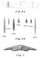
- In addition to the naked LED-light source one can use secondary optics, such as a lens, a reflector, etc, which modify the light distribution.
By combining different types of LED-light sources with different types of secondary optics, one arrives at numerous light distributions defining typical beams (including very intensive, semi narrow, asymmetrical beams).
Each such basic light distribution, representative of a specific LED-light source combined with a specific secondary optics, can be referred to as a "Light Distribution Unit" (LDU), as illustrated byfigures 6a and 6b . - Several LDU's together provide a global light distribution which can be suitable in a lighting device, such as a (street) lighting device or "luminaire, comprising multiple LED-light sources.
The luminaire can be seen as composed of facets emitting light in some direction. - Based on the different LDU's one can thus build a desired light distribution, by adding up different LDU's.
A typical or desired light distribution according to a specific pattern (or theoretical "lighting matrix"), as illustrated infigure 7 , can thus be "build" by adding up specific LDU's in the right direction (plane C and angle γ) as illustrated byfigure 8 . The chosen types, directions and numbers of LDU's will define the global light distribution. - Applying the principles referred to above (calculation methods and representation concepts for the relevant variables) one can calculate which LDU's to use for creating a desired global light distribution (as a specific pattern or "lighting matrix").
- In contrast to this approach street lightings involving LED-light sources according to the state of the art only provide
2 D light distribution, by using directed flat arrays of LED-light sources, or very limited 3 D light distribution ("cut off" light distribution), by using flat arrays of LED-light sources with (flat array) optical lens systems which can, to some extent, control the light in selected directions, but cannot send light to high γ angles.
These known approaches therefore are synonymous of short spacing between the luminaries. - It is the objective of the present invention to remedy the drawbacks encountered in the state of the art
by providing innovative - methods for designing,
- methods for manufacturing, and
- methods for controlling lighting devices,
- new types of lighting apparatus resulting from, respectively capable to implement, such methods.
- The invention there for provides a method for optimising the performance of a (street) lighting device involving multiple LED-light sources within a common frame, wherein specific LED-light sources are selected from a plurality of types of LED-light sources, specific secondary optics are selected from a plurality of types of secondary optics, for each selected LED light source, and specific orientations are selected for each of those LED-light sources and/or secondary optics, wherein variables representing the light distribution in function of direction coordinates are associated to each LED light source and its secondary optics, and wherein simulations of cumulative variables for multiple combinations of selected LED-light sources, selected secondary optics and selected orientations, are compared, using software assisted calculations, with selected global light distributions, so as to designate combinations of selected LED-light sources, selected secondary optics and selected orientations showing an optimal fit with said selected global light distributions.
- According to preferred features of the performance optimisation method according to the invention, the variables associated to each LED light source and its secondary optics are defined in accordance with
- a C-γ system of coordinates,
- Intensity tables,
- Polar diagrams of luminous intensity,
- Cartesian diagrams of luminous intensity,
- Utilisation factor curves, and/or
- Isolux diagrams.
- In a first specific and preferred embodiment to implement this method for optimising the performance of lighting devices involving multiple LED-light sources, once all necessary calculations in accordance with the basic concept of the invention (in particular the "flee eye" calculation concept) have been made (i.e. calculating the number and types of LED's to be used, the types of secondary optics to be associated to each LED, and the orientations of each of those), the invention proposes the use of "flexible print boards".
In this embodiment of the invention all the LED-light sources, secondary optics and necessary electronic components are mounted on a (flat) flexible print board (as illustrated byfigure 9 ) that can be placed on and adapted to any kind of mechanical support structure / three dimensional base structure, fixing the orientation of the LED-light sources (as illustrated byfigure 10 ).
The mechanical support structure can, for instance, involve a bended metal sheet, a deep drawn metal structure, a die cast metal structure, or a machined aluminium structure. - For meeting the objectives of the invention stated further above, the invention thus also specifically provides a first new method for designing and/ or making / manufacturing (street) lighting devices comprising multiple LED-sources within a common frame, with at least part of said LED-light sources being provided to a semi-flexible printed circuit, which method comprises the steps of
providing one or more types of three dimensional base structures for lighting devices,
providing one or more types of semi-flexible printed circuits adapted to receive the LED-light sources of the lighting device according to selected directions of the light sources, and
applying one semi flexible printed circuit on one three dimensional base structure of a type corresponding to said one semi flexible printed circuit,
so as to provide a defined three dimensional configuration of the LED-light sources' positions and orientations. - In a preferred embodiment of this manufacturing method for lighting devices, the semi-flexible printed circuits may very suitably involve several modules for one or more LED-light sources, with the capability to have each light source within one module directed into a selected direction and/or provided with individual optical means, and with each module having the capability to be bended according to a selected direction.
- In a second specific and preferred embodiment to implement this method for optimising the performance of a lighting devices involving multiple LED-light sources, once all necessary calculations in accordance with the basic concept of the invention have been made, the invention proposes the use of a "LED-modules on mechanical structures" ("Modular concept").
This modular concept may suitably involve
LED-modules, composed of - a heat sink structure, to dissipate, on its backside, the heat generated by the LED-light sources,
- a print board (rigid, or flexible for allowing multiple LED orientations on one module),
- LED-light sources,
- necessary electronic components,
- optional protection and/or tightness features,
- a three dimensional main structure ("wing"), providing an appropriate orientation for each module,
- a protector structure (global protector or individual protector for each module),
- optionally with a suitably designed "chimney" zone behind the "wing" zone, to evacuate the heat to the top of the device, into the ambient air,
- orienting each module in a specific direction in accordance with the required light distribution,
- dissipating the heat from the LED-light sources via the heat sink structures of the LED-modules.
- For meeting the objectives of the invention stated further above, the invention thus also specifically provides a second new method for designing and/ or making / manufacturing (street) lighting devices comprising multiple LED-sources within a common frame, with at least part of said LED-light sources being provided on modules, which method comprises providing
LED-modules composed of a heat sink structure, a print board, LED-light sources, necessary electronic components, and optional protection and/or tightness features, and
a mechanical structure, composed of a three dimensional main structure providing appropriate orientation for each module, a protector structure for said modules, with optionally a "chimney" zone to evacuate heat. - For meeting the stated objectives of the invention, the invention also provides a first new type of (street) lighting apparatus comprising multiple LED-light sources within a common frame (/ on a common support structure) with at least part of said LED-light sources being provided to a semi-flexible printed circuit, which apparatus comprises several modules of one or more LED-light sources, each module being a separately bendable part of a common semi-flexible printed circuit, each light source within one module being directed into a selected direction, and/or being provided with individual optical means, and each module being directed into a selected direction, whereas the power feed to each module, optionally each light source, is separately regulated by software controlled means.
- According to a preferred feature of the lighting apparatus according to the invention, the separately bendable parts of a common semi-flexible printed circuit defining said several modules are applied on a three dimensional base structure so as to provide a defined three dimensional configuration of the LED-light sources' positions and orientations.
- For meeting the stated objectives of the invention, the invention also provides a second new type of (street) lighting apparatus comprising multiple LED-light sources within a common frame (/ on a common support structure) with at least part of said LED-light sources being provided on modules, which apparatus comprises LED-modules composed of a heat sink structure, a print board, LED-light sources, necessary electronic components, and optional protection and/or tightness features, and
a mechanical structure, composed of a three dimensional main structure providing appropriate orientation for each module, a protector structure for said modules, with optionally a "chimney" zone to evacuate heat. - To meet the objectives stated further above the invention furthermore specifically provides a process for controlling a lighting device, in particular a street lighting device, involving multiple LED-light sources within a common frame, using several modules of one or more LED-light sources, each light source within one module being directed into a selected direction and/or provided with individual optical means, and each module being directed into a selected direction, whereas the power feed to each module, optionally each light source, is separately controlled.
- For meeting the objectives stated above, the invention also specifically provides a software assisted method for controlling the performance of (street) lighting devices involving multiple LED-light sources within a common frame, wherein each lighting device comprises several modules of one or more LED-light sources, each light source within one module being directed into a selected direction and/or provided with individual optical means, and each module being directed into a selected direction, whereas the power feed to each module, optionally each light source, is separately regulated by software controlled means.
- According to other preferred aspects of the invention, the manufacturing method, apparatus, control process and, respectively, software assisted method, according to the invention may involve one or more of the following further features :
- the light sources in one module are directed into selected cooperating directions,
- the power feed to each module, optionally each light source, is separately controlled in respect of amperage ("dimmability") and / or frequency.
- An important feature of the lighting concepts disclosed above resides in the fact that they consist of multi-source concepts and that the light sources can be easily dimmed (reducing of light intensity) or switched on and off, by using appropriate electronic drivers (as such well known in the art).
- This provides for optimal adaptation of the light distribution to various parameters, based on the facets concept and by controlling the light intensity of some LED-light sources in some directions, with even the possibility to modify the colour of the emitted light by using different types of coloured LED-light sources or RGB LED sources.
Such modification of the light distribution and / or colour distribution can thus adapt the photometrical performance of a lighting device according to many parameters, such as - climate, for instance due to rain, snow, frost, fog, ...
- time, for instance due to ageing of the road surface leading to changed reflection characteristics, clogging of the road surface, renovation of the road surface, modification of light level with time (day, evening, night, ...), seasons ("warm white" during winter, "cool white" during summer)
- traffic, for instance due to density of traffic, presence of accident or parked vehicle, traffic speed, type of vehicles (cars, trucks, ...)
- geometry, for instance due to the configuration of the road (width, curvature, ...), spacing between lighting poles, specificities and singularities (round about, crossing, zebra crossing, ...)
- geography, for instance according to different countries, specifications, norms (light level, colour, ...) - adaptation to different local requirements
However, in the laboratory, the photometric measurement of such a light distribution is performed in 8 C-planes (each 45° apart), and the intensity value for each gamma angle is the average of the values in the 8 C-planes.
For other types of luminaries (floodlights, tunnel luminaries, industrial non-circular luminaries, etc), the polar curves of intensity are generally given for the two longitudinal half-C-planes (0° and 180°) and the two transverse half-C-planes (90° and 270°) to the luminaire.

Using the concepts referred to here above one can thus, for instance, represent the light distribution of a single LED by a polar diagram as illustrated in
Each LED has its own specific light distribution.
Claims (14)
- Method for optimising the performance of a (street) lighting device involving multiple LED-light sources within a common frame, characterised in that specific LED-light sources are selected from a plurality of types of LED-light sources, specific secondary optics are selected from a plurality of types of secondary optics, for each selected LED light source, and specific orientations are selected for each of those LED-light sources and/or secondary optics, in that variables representing the light distribution in function of direction coordinates are associated to each LED light source and its secondary optics, and in that simulations of cumulative variables for multiple combinations of selected LED-light sources, selected secondary optics and selected orientations, are compared, using software assisted calculations, with selected global light distributions, so as to designate combinations of selected LED-light sources, selected secondary optics and selected orientations showing an optimal fit with said selected global light distributions.
- Performance optimisation method according to claim 1, characterised in that said variables are associated to each LED light source and its secondary optics according toa C-γ system of coordinates,Intensity tables,Polar diagrams of luminous intensity,Cartesian diagrams of luminous intensity,Utilisation factor curves, and/orIsolux diagrams.
- Method for manufacturing lighting devices comprising multiple LED-sources within a common frame, with at least part of said LED-light sources being provided to a semi-flexible printed circuit, characterised in that said method comprises the steps of
providing one or more types of three dimensional base structures for lighting devices,
providing one or more types of semi-flexible printed circuits adapted to receive the LED-light sources of the lighting device according to selected directions of the light sources, and
applying one semi flexible printed circuit on one three dimensional base structure of a type corresponding to said one semi flexible printed circuit,
so as to provide a defined three dimensional configuration of the LED-light sources' positions and orientations. - Manufacturing method according to claim 3, characterised in that said semi-flexible printed circuits comprise several modules of one or more LED-light sources, each module being a separately bendable part of said semi-flexible printed circuit, each light source within one module being directed into a selected direction, and/or being provided with individual optical means, and each module being directed into a selected direction, whereas the power feed to each module, optionally each light source, is separately regulated by software controlled means.
- Manufacturing method according to any one of claims 3 and 4, characterised in that said semi-flexible printed circuits involve several modules for one or more LED-light sources, with the capability to have each light source within one module directed into a selected direction and/or provided with individual optical means, and with each module having the capability to be bended according to a selected direction.
- Method for manufacturing lighting devices comprising multiple LED-sources within a common frame, with at least part of said LED-light sources being provided on modules, characterised in that said method comprises providing
LED-modules composed of a heat sink structure, a print board, LED-light sources, necessary electronic components, and optional protection and/or tightness features, and
a mechanical structure, composed of a three dimensional main structure providing appropriate orientation for each module, a protector structure for said modules, with optionally a "chimney" zone to evacuate heat. - Manufacturing method according to any one of claims 3 to 6, characterised in that said three dimensional configuration of the LED-light sources' positions and orientations results from a method according to any one of claims 1 and 2.
- Street lighting apparatus comprising multiple LED-light sources within a common frame (/ on a common support structure) with at least part of said LED-light sources being provided to a semi-flexible printed circuit, characterised in that said apparatus comprises several modules of one or more LED-light sources, each module being a separately bendable part of a common semi-flexible printed circuit, each light source within one module being directed into a selected direction, and/or being provided with individual optical means, and each module being directed into a selected direction, whereas the power feed to each module, optionally each light source, is separately regulated by software controlled means
- Street lighting apparatus according to claim 7, characterised in that said separately bendable parts of a common semi-flexible printed circuit defining said several modules are applied on a three dimensional base structure so as to provide a defined three dimensional configuration of the LED-light sources' positions and orientations.
- Street lighting apparatus comprising multiple LED-light sources within a common frame (/ on a common support structure) with at least part of said LED-light sources being provided on modules, characterised in that said apparatus comprises
LED-modules composed of a heat sink structure, a print board, LED-light sources, necessary electronic components, and optional protection and/or tightness features, and
a mechanical structure, composed of a three dimensional main structure providing appropriate orientation for each module, a protector structure for said modules, with optionally a "chimney" zone to evacuate heat. - Process for controlling a (street) lighting device involving multiple LED-light sources within a common frame, characterised in that several modules of one or more LED-light sources are used, each light source within one module being directed into a selected direction and/or provided with individual optical means, and each module being directed into a selected direction, whereas the power feed to each module, optionally each light source, is separately controlled.
- Software assisted method for controlling the performance of (street) lighting devices involving multiple LED-light sources within a common frame, characterised in that each lighting device comprises several modules of one or more LED-light sources, each light source within one module being directed into a selected direction and/or provided with individual optical means, and each module being directed into a selected direction, whereas the power feed to each module, optionally each light source, is separately regulated by software controlled means.
- Performance optimisation method, manufacturing method, street light apparatus, controlling process or software assisted method according to any one of claims 4 - 12, characterised in that the light sources in one module are directed into selected cooperating directions.
- Performance optimisation method, manufacturing method, street light apparatus, controlling process or software assisted method according to any one of claims 4 - 13, characterised in that the power feed to each module, optionally each light source, is separately controlled in respect of amperage ("dimability") and / or frequency.
Priority Applications (2)
| Application Number | Priority Date | Filing Date | Title |
|---|---|---|---|
| EP07100432A EP1945007B1 (en) | 2007-01-11 | 2007-01-11 | Performance optimisation method of LED lighting devices |
| ES07100432T ES2392354T3 (en) | 2007-01-11 | 2007-01-11 | Performance optimization method of LED lighting devices |
Applications Claiming Priority (1)
| Application Number | Priority Date | Filing Date | Title |
|---|---|---|---|
| EP07100432A EP1945007B1 (en) | 2007-01-11 | 2007-01-11 | Performance optimisation method of LED lighting devices |
Publications (2)
| Publication Number | Publication Date |
|---|---|
| EP1945007A1 true EP1945007A1 (en) | 2008-07-16 |
| EP1945007B1 EP1945007B1 (en) | 2012-09-19 |
Family
ID=38142262
Family Applications (1)
| Application Number | Title | Priority Date | Filing Date |
|---|---|---|---|
| EP07100432A Active EP1945007B1 (en) | 2007-01-11 | 2007-01-11 | Performance optimisation method of LED lighting devices |
Country Status (2)
| Country | Link |
|---|---|
| EP (1) | EP1945007B1 (en) |
| ES (1) | ES2392354T3 (en) |
Cited By (6)
| Publication number | Priority date | Publication date | Assignee | Title |
|---|---|---|---|---|
| WO2009107085A3 (en) * | 2008-02-26 | 2009-12-10 | Easy International S.R.L. | Led lamp and method for its design |
| EP2133622A1 (en) | 2008-06-12 | 2009-12-16 | Schreder | Street lighting apparatus with multiple LED-light sources |
| EP2177812A1 (en) * | 2008-08-19 | 2010-04-21 | Golden Valley Optoelectronic Co., Ltd. | High power led lamp |
| ITBA20090011A1 (en) * | 2009-03-14 | 2010-09-15 | Sud Segnal Srl | LIGHTING SYSTEM FOR PUBLIC LIGHTING |
| WO2011154756A3 (en) * | 2010-06-09 | 2012-03-29 | Wemont Kft. | Method for constructing a lighting device with discrete light sources and thus obtained lighting device |
| EP2365740A3 (en) * | 2010-03-12 | 2013-08-21 | Omron Corporation | Illuminating device |
Citations (11)
| Publication number | Priority date | Publication date | Assignee | Title |
|---|---|---|---|---|
| WO1999050596A2 (en) * | 1998-03-26 | 1999-10-07 | Otkrytoe Aktsionernoe Obschestvo Lomo | Illumination device for generating non-symmetric light beam, optical lens array and optical lens |
| JPH11329022A (en) * | 1998-05-22 | 1999-11-30 | Stanley Electric Co Ltd | Signal light device for vehicle |
| GB2360461A (en) * | 2000-03-23 | 2001-09-26 | Photo Therapeutics Ltd | Therapeutic light source and metho |
| US20030090910A1 (en) * | 2001-11-11 | 2003-05-15 | Hsing Chen | Light emitting diode lamp |
| US20030193807A1 (en) * | 2002-04-16 | 2003-10-16 | Alexander Rizkin | LED-based elevated omnidirectional airfield light |
| JP2005196983A (en) * | 2003-12-26 | 2005-07-21 | Matsushita Electric Works Ltd | Luminaire using light emitting diode |
| WO2005090852A2 (en) * | 2004-03-18 | 2005-09-29 | Lighting Science Group Corporation | Led light bulb using a flexible substrate |
| US20050254264A1 (en) * | 2004-05-12 | 2005-11-17 | Sidwell Steven C | Thermally efficient LED bulb |
| ES2255885A1 (en) * | 2006-03-08 | 2006-07-01 | Javier Fernandez De Valderrama Alvarez | Flexible light emitter |
| US7165863B1 (en) * | 2004-09-23 | 2007-01-23 | Pricilla G. Thomas | Illumination system |
| US20070019432A1 (en) * | 2005-07-25 | 2007-01-25 | Takeshi Shimada | Led light source vehicular lamp |
-
2007
- 2007-01-11 EP EP07100432A patent/EP1945007B1/en active Active
- 2007-01-11 ES ES07100432T patent/ES2392354T3/en active Active
Patent Citations (11)
| Publication number | Priority date | Publication date | Assignee | Title |
|---|---|---|---|---|
| WO1999050596A2 (en) * | 1998-03-26 | 1999-10-07 | Otkrytoe Aktsionernoe Obschestvo Lomo | Illumination device for generating non-symmetric light beam, optical lens array and optical lens |
| JPH11329022A (en) * | 1998-05-22 | 1999-11-30 | Stanley Electric Co Ltd | Signal light device for vehicle |
| GB2360461A (en) * | 2000-03-23 | 2001-09-26 | Photo Therapeutics Ltd | Therapeutic light source and metho |
| US20030090910A1 (en) * | 2001-11-11 | 2003-05-15 | Hsing Chen | Light emitting diode lamp |
| US20030193807A1 (en) * | 2002-04-16 | 2003-10-16 | Alexander Rizkin | LED-based elevated omnidirectional airfield light |
| JP2005196983A (en) * | 2003-12-26 | 2005-07-21 | Matsushita Electric Works Ltd | Luminaire using light emitting diode |
| WO2005090852A2 (en) * | 2004-03-18 | 2005-09-29 | Lighting Science Group Corporation | Led light bulb using a flexible substrate |
| US20050254264A1 (en) * | 2004-05-12 | 2005-11-17 | Sidwell Steven C | Thermally efficient LED bulb |
| US7165863B1 (en) * | 2004-09-23 | 2007-01-23 | Pricilla G. Thomas | Illumination system |
| US20070019432A1 (en) * | 2005-07-25 | 2007-01-25 | Takeshi Shimada | Led light source vehicular lamp |
| ES2255885A1 (en) * | 2006-03-08 | 2006-07-01 | Javier Fernandez De Valderrama Alvarez | Flexible light emitter |
Cited By (6)
| Publication number | Priority date | Publication date | Assignee | Title |
|---|---|---|---|---|
| WO2009107085A3 (en) * | 2008-02-26 | 2009-12-10 | Easy International S.R.L. | Led lamp and method for its design |
| EP2133622A1 (en) | 2008-06-12 | 2009-12-16 | Schreder | Street lighting apparatus with multiple LED-light sources |
| EP2177812A1 (en) * | 2008-08-19 | 2010-04-21 | Golden Valley Optoelectronic Co., Ltd. | High power led lamp |
| ITBA20090011A1 (en) * | 2009-03-14 | 2010-09-15 | Sud Segnal Srl | LIGHTING SYSTEM FOR PUBLIC LIGHTING |
| EP2365740A3 (en) * | 2010-03-12 | 2013-08-21 | Omron Corporation | Illuminating device |
| WO2011154756A3 (en) * | 2010-06-09 | 2012-03-29 | Wemont Kft. | Method for constructing a lighting device with discrete light sources and thus obtained lighting device |
Also Published As
| Publication number | Publication date |
|---|---|
| EP1945007B1 (en) | 2012-09-19 |
| ES2392354T3 (en) | 2012-12-10 |
Similar Documents
| Publication | Publication Date | Title |
|---|---|---|
| US8517566B2 (en) | Apparatus, method, and system for roadway lighting using solid-state light sources | |
| EP1945007B1 (en) | Performance optimisation method of LED lighting devices | |
| EP3659396B1 (en) | Lighting apparatus with controllable light distribution | |
| CN103765082B (en) | Lighting device | |
| US20230024141A1 (en) | System and Method for Driving and Controlling Light Sources | |
| US20020159274A1 (en) | Area lighting device using discrete light sources, such as leds | |
| US20080291664A1 (en) | Carriageway-Marking Device and System | |
| KR101325142B1 (en) | LED lighting device capable of arbitrary light-distribution | |
| JP2007242258A (en) | Lighting system | |
| CN102080787A (en) | Light emitting module and automotive lamp | |
| CN103807716A (en) | Lighting device including semiconductor light source | |
| CN104169641A (en) | Light-emitting device and lighting apparatus for vehicle | |
| EP2133622A1 (en) | Street lighting apparatus with multiple LED-light sources | |
| CN105980769A (en) | Comfortable distributed LED lighting | |
| EP2375130B1 (en) | Lighting module for tunnel, road or street light | |
| KR20170000550A (en) | LED Lighting For Road | |
| EP2748524B1 (en) | A lighting device and a road lighting luminaire comprising the lighting device. | |
| CN202253126U (en) | Glare-free light-emitting diode (LED) streetlamp | |
| KR20130028408A (en) | Led lighting equipment | |
| KR101503498B1 (en) | Lighting device for street | |
| WO2001025683A1 (en) | Area lighting device using discrete light sources, such as leds | |
| US20230012078A1 (en) | Illumination system for outdoor regions | |
| CN102853327B (en) | The LED street lamp of free from glare | |
| JP2009245621A (en) | Outdoor illuminating light unit and outdoor illuminating light | |
| CN106439734A (en) | High-efficiency illumination structure of lamp reflecting cover |
Legal Events
| Date | Code | Title | Description |
|---|---|---|---|
| PUAI | Public reference made under article 153(3) epc to a published international application that has entered the european phase |
Free format text: ORIGINAL CODE: 0009012 |
|
| AK | Designated contracting states |
Kind code of ref document: A1 Designated state(s): AT BE BG CH CY CZ DE DK EE ES FI FR GB GR HU IE IS IT LI LT LU LV MC NL PL PT RO SE SI SK TR |
|
| AX | Request for extension of the european patent |
Extension state: AL BA HR MK RS |
|
| 17P | Request for examination filed |
Effective date: 20090114 |
|
| AKX | Designation fees paid |
Designated state(s): AT BE BG CH CY CZ DE DK EE ES FI FR GB GR HU IE IS IT LI LT LU LV MC NL PL PT RO SE SI SK TR |
|
| AXX | Extension fees paid |
Extension state: RS Payment date: 20090114 |
|
| 17Q | First examination report despatched |
Effective date: 20090317 |
|
| GRAP | Despatch of communication of intention to grant a patent |
Free format text: ORIGINAL CODE: EPIDOSNIGR1 |
|
| GRAS | Grant fee paid |
Free format text: ORIGINAL CODE: EPIDOSNIGR3 |
|
| GRAA | (expected) grant |
Free format text: ORIGINAL CODE: 0009210 |
|
| AK | Designated contracting states |
Kind code of ref document: B1 Designated state(s): AT BE BG CH CY CZ DE DK EE ES FI FR GB GR HU IE IS IT LI LT LU LV MC NL PL PT RO SE SI SK TR |
|
| AX | Request for extension of the european patent |
Extension state: RS |
|
| REG | Reference to a national code |
Ref country code: GB Ref legal event code: FG4D |
|
| REG | Reference to a national code |
Ref country code: CH Ref legal event code: EP |
|
| REG | Reference to a national code |
Ref country code: IE Ref legal event code: FG4D |
|
| REG | Reference to a national code |
Ref country code: AT Ref legal event code: REF Ref document number: 576548 Country of ref document: AT Kind code of ref document: T Effective date: 20121015 |
|
| REG | Reference to a national code |
Ref country code: DE Ref legal event code: R096 Ref document number: 602007025530 Country of ref document: DE Effective date: 20121108 |
|
| REG | Reference to a national code |
Ref country code: NL Ref legal event code: T3 |
|
| REG | Reference to a national code |
Ref country code: ES Ref legal event code: FG2A Ref document number: 2392354 Country of ref document: ES Kind code of ref document: T3 Effective date: 20121210 |
|
| PG25 | Lapsed in a contracting state [announced via postgrant information from national office to epo] |
Ref country code: LT Free format text: LAPSE BECAUSE OF FAILURE TO SUBMIT A TRANSLATION OF THE DESCRIPTION OR TO PAY THE FEE WITHIN THE PRESCRIBED TIME-LIMIT Effective date: 20120919 Ref country code: FI Free format text: LAPSE BECAUSE OF FAILURE TO SUBMIT A TRANSLATION OF THE DESCRIPTION OR TO PAY THE FEE WITHIN THE PRESCRIBED TIME-LIMIT Effective date: 20120919 Ref country code: CY Free format text: LAPSE BECAUSE OF FAILURE TO SUBMIT A TRANSLATION OF THE DESCRIPTION OR TO PAY THE FEE WITHIN THE PRESCRIBED TIME-LIMIT Effective date: 20120919 |
|
| REG | Reference to a national code |
Ref country code: AT Ref legal event code: MK05 Ref document number: 576548 Country of ref document: AT Kind code of ref document: T Effective date: 20120919 |
|
| REG | Reference to a national code |
Ref country code: LT Ref legal event code: MG4D Effective date: 20120919 |
|
| PG25 | Lapsed in a contracting state [announced via postgrant information from national office to epo] |
Ref country code: SI Free format text: LAPSE BECAUSE OF FAILURE TO SUBMIT A TRANSLATION OF THE DESCRIPTION OR TO PAY THE FEE WITHIN THE PRESCRIBED TIME-LIMIT Effective date: 20120919 Ref country code: LV Free format text: LAPSE BECAUSE OF FAILURE TO SUBMIT A TRANSLATION OF THE DESCRIPTION OR TO PAY THE FEE WITHIN THE PRESCRIBED TIME-LIMIT Effective date: 20120919 Ref country code: SE Free format text: LAPSE BECAUSE OF FAILURE TO SUBMIT A TRANSLATION OF THE DESCRIPTION OR TO PAY THE FEE WITHIN THE PRESCRIBED TIME-LIMIT Effective date: 20120919 Ref country code: GR Free format text: LAPSE BECAUSE OF FAILURE TO SUBMIT A TRANSLATION OF THE DESCRIPTION OR TO PAY THE FEE WITHIN THE PRESCRIBED TIME-LIMIT Effective date: 20121220 |
|
| PG25 | Lapsed in a contracting state [announced via postgrant information from national office to epo] |
Ref country code: EE Free format text: LAPSE BECAUSE OF FAILURE TO SUBMIT A TRANSLATION OF THE DESCRIPTION OR TO PAY THE FEE WITHIN THE PRESCRIBED TIME-LIMIT Effective date: 20120919 Ref country code: RO Free format text: LAPSE BECAUSE OF FAILURE TO SUBMIT A TRANSLATION OF THE DESCRIPTION OR TO PAY THE FEE WITHIN THE PRESCRIBED TIME-LIMIT Effective date: 20120919 Ref country code: CZ Free format text: LAPSE BECAUSE OF FAILURE TO SUBMIT A TRANSLATION OF THE DESCRIPTION OR TO PAY THE FEE WITHIN THE PRESCRIBED TIME-LIMIT Effective date: 20120919 Ref country code: IS Free format text: LAPSE BECAUSE OF FAILURE TO SUBMIT A TRANSLATION OF THE DESCRIPTION OR TO PAY THE FEE WITHIN THE PRESCRIBED TIME-LIMIT Effective date: 20130119 |
|
| PG25 | Lapsed in a contracting state [announced via postgrant information from national office to epo] |
Ref country code: PL Free format text: LAPSE BECAUSE OF FAILURE TO SUBMIT A TRANSLATION OF THE DESCRIPTION OR TO PAY THE FEE WITHIN THE PRESCRIBED TIME-LIMIT Effective date: 20120919 Ref country code: SK Free format text: LAPSE BECAUSE OF FAILURE TO SUBMIT A TRANSLATION OF THE DESCRIPTION OR TO PAY THE FEE WITHIN THE PRESCRIBED TIME-LIMIT Effective date: 20120919 Ref country code: PT Free format text: LAPSE BECAUSE OF FAILURE TO SUBMIT A TRANSLATION OF THE DESCRIPTION OR TO PAY THE FEE WITHIN THE PRESCRIBED TIME-LIMIT Effective date: 20130121 |
|
| PG25 | Lapsed in a contracting state [announced via postgrant information from national office to epo] |
Ref country code: AT Free format text: LAPSE BECAUSE OF FAILURE TO SUBMIT A TRANSLATION OF THE DESCRIPTION OR TO PAY THE FEE WITHIN THE PRESCRIBED TIME-LIMIT Effective date: 20120919 |
|
| PLBE | No opposition filed within time limit |
Free format text: ORIGINAL CODE: 0009261 |
|
| STAA | Information on the status of an ep patent application or granted ep patent |
Free format text: STATUS: NO OPPOSITION FILED WITHIN TIME LIMIT |
|
| PG25 | Lapsed in a contracting state [announced via postgrant information from national office to epo] |
Ref country code: DK Free format text: LAPSE BECAUSE OF FAILURE TO SUBMIT A TRANSLATION OF THE DESCRIPTION OR TO PAY THE FEE WITHIN THE PRESCRIBED TIME-LIMIT Effective date: 20120919 Ref country code: BG Free format text: LAPSE BECAUSE OF FAILURE TO SUBMIT A TRANSLATION OF THE DESCRIPTION OR TO PAY THE FEE WITHIN THE PRESCRIBED TIME-LIMIT Effective date: 20121219 |
|
| 26N | No opposition filed |
Effective date: 20130620 |
|
| PG25 | Lapsed in a contracting state [announced via postgrant information from national office to epo] |
Ref country code: MC Free format text: LAPSE BECAUSE OF NON-PAYMENT OF DUE FEES Effective date: 20130131 |
|
| REG | Reference to a national code |
Ref country code: DE Ref legal event code: R097 Ref document number: 602007025530 Country of ref document: DE Effective date: 20130620 |
|
| REG | Reference to a national code |
Ref country code: IE Ref legal event code: MM4A |
|
| PG25 | Lapsed in a contracting state [announced via postgrant information from national office to epo] |
Ref country code: IE Free format text: LAPSE BECAUSE OF NON-PAYMENT OF DUE FEES Effective date: 20130111 |
|
| PG25 | Lapsed in a contracting state [announced via postgrant information from national office to epo] |
Ref country code: TR Free format text: LAPSE BECAUSE OF FAILURE TO SUBMIT A TRANSLATION OF THE DESCRIPTION OR TO PAY THE FEE WITHIN THE PRESCRIBED TIME-LIMIT Effective date: 20120919 |
|
| PG25 | Lapsed in a contracting state [announced via postgrant information from national office to epo] |
Ref country code: HU Free format text: LAPSE BECAUSE OF FAILURE TO SUBMIT A TRANSLATION OF THE DESCRIPTION OR TO PAY THE FEE WITHIN THE PRESCRIBED TIME-LIMIT; INVALID AB INITIO Effective date: 20070111 Ref country code: LU Free format text: LAPSE BECAUSE OF NON-PAYMENT OF DUE FEES Effective date: 20130111 |
|
| REG | Reference to a national code |
Ref country code: FR Ref legal event code: PLFP Year of fee payment: 10 |
|
| REG | Reference to a national code |
Ref country code: FR Ref legal event code: PLFP Year of fee payment: 11 |
|
| REG | Reference to a national code |
Ref country code: FR Ref legal event code: PLFP Year of fee payment: 12 |
|
| PGFP | Annual fee paid to national office [announced via postgrant information from national office to epo] |
Ref country code: CH Payment date: 20200127 Year of fee payment: 14 |
|
| REG | Reference to a national code |
Ref country code: CH Ref legal event code: PL |
|
| PG25 | Lapsed in a contracting state [announced via postgrant information from national office to epo] |
Ref country code: LI Free format text: LAPSE BECAUSE OF NON-PAYMENT OF DUE FEES Effective date: 20210131 Ref country code: CH Free format text: LAPSE BECAUSE OF NON-PAYMENT OF DUE FEES Effective date: 20210131 |
|
| PGFP | Annual fee paid to national office [announced via postgrant information from national office to epo] |
Ref country code: ES Payment date: 20230201 Year of fee payment: 17 |
|
| PGFP | Annual fee paid to national office [announced via postgrant information from national office to epo] |
Ref country code: IT Payment date: 20230103 Year of fee payment: 17 |
|
| P01 | Opt-out of the competence of the unified patent court (upc) registered |
Effective date: 20230516 |
|
| PGFP | Annual fee paid to national office [announced via postgrant information from national office to epo] |
Ref country code: GB Payment date: 20231219 Year of fee payment: 18 |
|
| PGFP | Annual fee paid to national office [announced via postgrant information from national office to epo] |
Ref country code: NL Payment date: 20231219 Year of fee payment: 18 Ref country code: FR Payment date: 20231219 Year of fee payment: 18 |
|
| PGFP | Annual fee paid to national office [announced via postgrant information from national office to epo] |
Ref country code: BE Payment date: 20231219 Year of fee payment: 18 |
|
| PGFP | Annual fee paid to national office [announced via postgrant information from national office to epo] |
Ref country code: ES Payment date: 20240202 Year of fee payment: 18 |
|
| PGFP | Annual fee paid to national office [announced via postgrant information from national office to epo] |
Ref country code: DE Payment date: 20231219 Year of fee payment: 18 |