EP1944750A2 - Keyboard-type percussion instrument - Google Patents
Keyboard-type percussion instrument Download PDFInfo
- Publication number
- EP1944750A2 EP1944750A2 EP08000028A EP08000028A EP1944750A2 EP 1944750 A2 EP1944750 A2 EP 1944750A2 EP 08000028 A EP08000028 A EP 08000028A EP 08000028 A EP08000028 A EP 08000028A EP 1944750 A2 EP1944750 A2 EP 1944750A2
- Authority
- EP
- European Patent Office
- Prior art keywords
- keys
- sounding
- pedal
- members
- tone
- Prior art date
- Legal status (The legal status is an assumption and is not a legal conclusion. Google has not performed a legal analysis and makes no representation as to the accuracy of the status listed.)
- Withdrawn
Links
- 238000009527 percussion Methods 0.000 title claims abstract description 39
- 230000007246 mechanism Effects 0.000 claims description 24
- 230000009471 action Effects 0.000 claims description 21
- 230000033001 locomotion Effects 0.000 claims description 21
- 230000008859 change Effects 0.000 claims description 2
- 230000000994 depressogenic effect Effects 0.000 abstract description 12
- 230000003247 decreasing effect Effects 0.000 abstract description 3
- 239000011295 pitch Substances 0.000 description 55
- 230000000875 corresponding effect Effects 0.000 description 38
- 238000005192 partition Methods 0.000 description 24
- 238000010276 construction Methods 0.000 description 9
- 230000008878 coupling Effects 0.000 description 6
- 238000010168 coupling process Methods 0.000 description 6
- 238000005859 coupling reaction Methods 0.000 description 6
- 230000007423 decrease Effects 0.000 description 3
- 229910052751 metal Inorganic materials 0.000 description 3
- 239000002184 metal Substances 0.000 description 3
- 229910052782 aluminium Inorganic materials 0.000 description 2
- XAGFODPZIPBFFR-UHFFFAOYSA-N aluminium Chemical compound [Al] XAGFODPZIPBFFR-UHFFFAOYSA-N 0.000 description 2
- 230000001276 controlling effect Effects 0.000 description 2
- 229910000838 Al alloy Inorganic materials 0.000 description 1
- 229920001410 Microfiber Polymers 0.000 description 1
- 239000004677 Nylon Substances 0.000 description 1
- 229910000831 Steel Inorganic materials 0.000 description 1
- 230000001133 acceleration Effects 0.000 description 1
- 239000002649 leather substitute Substances 0.000 description 1
- 238000012423 maintenance Methods 0.000 description 1
- 239000000463 material Substances 0.000 description 1
- 230000004048 modification Effects 0.000 description 1
- 238000012986 modification Methods 0.000 description 1
- 239000004745 nonwoven fabric Substances 0.000 description 1
- 229920001778 nylon Polymers 0.000 description 1
- 230000004044 response Effects 0.000 description 1
- 230000000717 retained effect Effects 0.000 description 1
- 239000010959 steel Substances 0.000 description 1
- 239000002023 wood Substances 0.000 description 1
Images







Classifications
-
- G—PHYSICS
- G10—MUSICAL INSTRUMENTS; ACOUSTICS
- G10D—STRINGED MUSICAL INSTRUMENTS; WIND MUSICAL INSTRUMENTS; ACCORDIONS OR CONCERTINAS; PERCUSSION MUSICAL INSTRUMENTS; AEOLIAN HARPS; SINGING-FLAME MUSICAL INSTRUMENTS; MUSICAL INSTRUMENTS NOT OTHERWISE PROVIDED FOR
- G10D13/00—Percussion musical instruments; Details or accessories therefor
- G10D13/01—General design of percussion musical instruments
- G10D13/08—Multi-toned musical instruments with sonorous bars, blocks, forks, gongs, plates, rods or teeth
- G10D13/09—Multi-toned musical instruments with sonorous bars, blocks, forks, gongs, plates, rods or teeth with keyboards
Definitions
- the present invention relates to a keyboard-type percussion instrument having sounding members each adapted to generate a musical tone when struck.
- a keyboard-type tone plate percussion instrument which includes a plurality of keys, hammer actions respectively corresponding to the keys, rectangular tone plates (sounding members) each adapted to be struck by a corresponding hammer action, and resonance boxes disposed above the tone plates and causing tones generated by tone plates to resonate therein (see, for example, Japanese Utility Model Laid-open Publication No. 05-081895 ).
- the hammer actions of this tone plate percussion instrument are similar to those of a grand piano. When any of the keys is depressed by a player, a corresponding hammer action strikes a tone plate concerned, whereby the tone plate vibrates to generate a musical tone of a tone pitch proper to the tone plate.
- a grand piano of the type including hammer actions similar to those disclosed in Japanese Utility Model Laid-open Publication No. 05-081895 is provided with a soft pedal that makes it easy to generate a soft tone.
- a plurality of strings are provided for each key, and when any of the keys is depressed by a player, a corresponding plurality of strings are struck.
- the soft pedal is stepped on by the player, a positional relation between each hammer and corresponding strings is changed to decrease the number of strings struck by the hammer, whereby the volume of a generated musical tone is made small.
- the keyboard-type tone plate percussion instrument disclosed in Japanese Utility Model Laid-open Publication No. 05-081895 includes hammer actions similar to those of a grand piano, there is only provided one tone plate for each key.
- this tone plate percussion instrument therefore, it is impossible to adopt a construction for decreasing the volume of tone by reducing the number of tone plates struck by a corresponding hammer, and thus the player wishing to produce a soft tone is required to finely adjust a key depression force, making it difficult to produce a soft tone in a musical performance.
- the present invention provides a keyboard-type percussion instrument having sounding members arranged to correspond to respective ones of keys and capable of improving musical performance in soft tone.
- a keyboard-type percussion instrument comprising a plurality of keys, sounding members arranged to correspond to respective ones of the keys and each adapted to generate, when struck, a musical tone of a tone pitch proper to the sounding member, action mechanisms arranged to correspond to respective ones of the keys and each having a hammer adapted to strike a corresponding one of the sounding members in accordance with a motion of a corresponding one of the keys, a pedal, and a standby position adjusting unit adapted to change positions of the hammers observed when the plurality of keys are in a standby state in accordance with a motion of the pedal.
- the plurality of keys can each be supported by a fulcrum for pivotal motion around the fulcrum
- each of the hammers can be adapted to strike a corresponding one of the sounding members with a pivotal motion of a corresponding one of the keys
- the standby position adjusting unit can be adapted to move the positions of the hammers observed when the plurality of keys are in the standby state in accordance with a motion of the pedal.
- the positions of the hammers observed when the plurality of keys are in the standby state and having been changed in accordance with a motion of the pedal can be fixed by the pedal being operated in a predetermined direction.
- the plurality of keys and the action mechanisms arranged to correspond to respective ones of the keys can be unitized by being supported by a key frame.
- the keyboard-type percussion instrument of this invention having sounding members arranged to correspond to respective ones of keys can improve musical performance in soft tone.
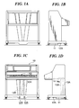
- FIG. 1A is a rear view of a keyboard-type percussion instrument according to one embodiment of this invention.
- FIG. 1B is a left side view of the percussion instrument
- FIG. 1C is a front view of the percussion instrument
- FIG. 1D is a right side view of the percussion instrument
- FIG. 2 is a schematic side view showing the interior of the percussion instrument
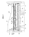
- FIG. 3 is a fragmentary front view of the interior of an upper part of the percussion instrument
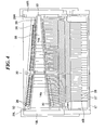
- FIG. 4 is a plan view showing the interior of the percussion instrument
- FIG. 5 is a front view of a tone generator unit of the percussion instrument
- FIG. 6 is a section view taken along line A-A in FIG. 5 ;
- FIG. 7 is a bottom view of the tone generator unit
- FIG. 8A is a plan view of one of sounding members of the tone generator unit
- FIG. 8B is a side view of the sounding member
- FIG. 9A is a side view of one of fasteners used for mounting the sounding members to a resonance box of the tone generator unit;
- FIG. 9B is a fragmentary enlarged view of the fastener
- FIG. 9C is a side view of one of sounding members corresponding to a high-pitch range portion of the resonance box.
- FIG. 9D is a side view of one of sounding members corresponding to a mid-pitch range portion of the resonance box.
- FIG. 9E is a side view of one of sounding members corresponding to a low-pitch range portion of the resonance box.
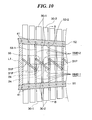
- FIG. 10 is a fragmentary enlarged view of the mid-pitch portion shown in FIG. 6 ;
- FIG. 11 is an external view of a supporting cord used for mounting the sounding members to the resonance box
- FIG. 12 is a fragmentary section view taken along line B-B in FIG. 10 .
- FIG. 13 is a fragmentary perspective view showing rear-side parts of a keybed and a key frame of the percussion instrument, together with a mechanism for vertically moving rear end portions of all the keys;
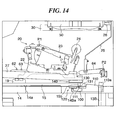
- FIG. 14 is an enlarged view showing a rear end portion of the key shown in FIG. 2 and its vicinity;
- FIG. 15 is an enlarged view showing the rear end portion of the key and its vicinity in a state where a soft pedal is stepped on;
- FIG. 16 is an enlarged view showing the rear end portion of the key in a state where the key frame is pulled out forward;
- FIG. 17A is an enlarged view showing the soft pedal and its vicinity in a state where the soft pedal is not stepped on; and FIG. 17B is an enlarged view showing the soft pedal and its vicinity in a state where the soft pedal is maintained in its stepped-on state.
- FIGS. 1A to 1D respectively show in rear view, left side view, front view, and right side view a keyboard-type percussion instrument 10 according to one embodiment of this invention.
- the side of the percussion instrument 10 toward a player is referred to as the front side thereof, and left and right directions thereof are determined in reference to the player facing the percussion instrument 10.
- the keyboard-type percussion instrument 10 is adapted to cause each of metallic sounding members to vibrate to generate a musical tone when the sounding member is struck.
- the percussion instrument 10 includes a keyboard KB having a plurality of white keys and black keys, a damper pedal 12A and a soft pedal 12B which are adapted to be operated by a foot of a player, and a pedal box 11 in which there are provided a mechanism for vertically moving a pedal coupling rod 13A in accordance with a motion of the damper pedal 12A and a mechanism for vertically moving a pedal coupling rod 13B in accordance with a motion of the soft pedal 12B.
- the damper pedal 12A is adapted to control vibration of the sounding members. Specifically, in a state that the damper pedal 12A is stepped on by the player, even if the key is no longer depressed by the player, the corresponding sounding member is not suppressed from vibrating. Thus, a time period for which a musical tone is sounded from the struck sounding member becomes longer as compared to the case where the damper pedal 12A is not stepped on.
- the soft pedal 12B is for controlling the volume of a tone generated by each sounding member. Provided that a key depression force applied by the player is the same, the volume of a tone generated when any of the sounding members is struck becomes smaller when the soft pedal 12B is stepped on by the player than when the soft pedal 12B is not stepped on.
- the mechanism for moving the pedal connecting rod 13B in the vertical direction in response to the upward and downward movement of the soft pedal 12B is the same as that of a grand piano.
- FIGS. 2 to 4 schematically show the interior of the percussion instrument 10 in side view, front view, and plan view.
- the percussion instrument 10 has an upper part thereof in which a tone generator unit UNT and a resonance box 50 are disposed.
- the tone generator unit UNT includes the sounding members 30 disposed to correspond to respective ones of the keys of the keyboard KB and adapted to generate musical tones.
- the resonance box 50 is adapted to cause musical tones generated by sounding members 30 to resonate therein.
- action mechanisms 20 having hammer felts 24 for striking the sounding members 30, damper mechanisms D for controlling the vibration of the sounding members 30, and a mechanism for vertically moving rear end portions of the keys in accordance with a motion of the pedal coupling rod 13B are provided below the tone generator unit UNT.
- FIG. 5 shows in front view the tone generator unit UNT
- FIG. 6 is a section view taken along line A-A in FIG. 5
- FIG. 7 shows in bottom view the tone generator unit UNT.
- the tone generator unit UNT includes the sounding members 30 provided to correspond to respective ones of the keys of the keyboard KB, and the resonance box 50 for causing musical tones generated by struck sounding members 30 to resonate therein.
- opposite end portions of the resonance box 50 are supported at their lower surfaces by supporting portions 29R, 29L respectively extending from right and left side plates 18R, 18L to the inside of the percussion instrument 10.
- the sounding members 30 are disposed below the resonance box 50 in the key arrangement direction of the keyboard KB.
- the sounding members 30 are arranged such that the leftmost and rightmost sounding members 30 as seen from the player are adapted to generate musical tones of the lowest and highest tone pitches, respectively.
- the sounding members 30 are arranged in a one-stage structure but not in an upper and lower two-stage structure.
- the action mechanisms 20 for striking the sounding members 30 are also arranged in a one-stage structure in the key arrangement direction of the keyboard KB.
- the sounding members 30 are made of aluminum.
- the material of the sounding members 30 is not limited to aluminum but may be an aluminum alloy, steel, or some other metal.
- the sounding members 30 corresponding to respective ones of the keys are different in length, width, and shape from one another. When struck by hammer felts 24, the sounding members 30 vibrate in many different forms to generate musical tones of tone pitches proper to respective ones of the sounding members.
- the sounding members 30 are divided into three sounding member groups 30A, 30B and 30C respectively belonging to high-, mid-, and low-pitch ranges.
- the sounding members 30 belonging to the group 30A are short in length in the longitudinal direction (forward-to-backward direction).
- the sounding members 30 belonging to the group 30B are longer in longitudinal length, and those members which belong to the group 30C are much longer in longitudinal length.
- the sounding members belonging to the group 30C are broad in width, and the sounding members 30 belonging to the group 30A are narrower in width than those belonging to the group 30C. It should be noted that the sounding members belonging to the same pitch range are the same in width from one another.
- FIGS. 8A and 8B show in plan view and right side view one of the sounding members 30 belonging to the sounding member group 30C (low-pitch range).
- This sounding member 30 has a lower surface thereof formed into a flat surface (adapted to be struck by the hammer felt 24) and front and rear end portions 32, 33 thereof thicker than an antinode portion 31 thereof (a longitudinally central portion of the sounding member where a vibration antinode can be formed).
- the sounding member 30 further includes first and second thinner portions 34, 35.
- the first thinner portion 34 is thinner than the antinode portion 31 and formed between the antinode portion 31 and the front end portion 32.
- the second thinner portion 35 is thinner than the antinode portion 31 and formed between the antinode portion 31 and the rear end portion 33.
- the center of the antinode portion 31 corresponds in position to the antinode center of vibration (hereinafter referred to as the "antinode center 31P").
- FIGS. 9C, 9D, and 9E show in side views sounding members 30 belonging to the sounding member groups 30A, 30B, and 30C, respectively.
- the sounding members 30 belonging to the groups 30A, 30B each have front and rear end portions 32, 33 thereof thinner than those of sounding members 30 belonging to the group 30C.
- the sounding members 30 belonging to the group 30A are not formed with portions corresponding to the first and second thinner portions 34, 35.
- the sounding member 30 is formed with supporting holes 36, 37 that extend therethrough at positions closer to the end portions of the sounding member than to the longitudinally central portion thereof. Vibration nodes can be formed in these positions.
- the sounding member 30 effectively generates a musical tone when caused to vibrate in a state where it is supported at the supporting holes 36, 37.
- the supporting holes 36, 37 each extend obliquely relative to the width direction of the sounding member 30 and not parallel to the width direction thereof.
- the resonance box 50 is formed into a box shape having an open lower surface, and has its front common wall 51 forming a front surface thereof, a rear common wall 52 forming a rear surface thereof, side walls 59A, 59B forming left and right side surfaces thereof, and lid members 56, 57 and 58 closing an upper surface thereof. As shown in FIG. 5 , the resonance box 50 is divided into low-, mid-, and high-pitch range portions 50A, 50B, and 50C.
- the low-pitch range portion 50A includes Helmholtz type resonance chambers RM1, which are the same in number as sounding members 30 disposed below the low-pitch range portion 50A and which are arranged to correspond to these sounding members 30.
- the mid-pitch range portion 50B of the resonance box 50 includes closed-tube type resonance chambers RM2, which are the same in number as sounding members 30 disposed below the mid-pitch range portion 50B and arranged to correspond to these sounding members 30.
- the high-pitch range portion 50C includes a single-type resonance box in which one resonance chamber RM3 is provided, which is common to sounding members 30 disposed below the high-pitch range portion 50C.
- Each of the front and rear common walls 51, 52 of the resonance box 50 is comprised of a plate-like member having two rectangular portions thereof corresponding to the low- and high-pitch range portions 50A, 50C of the resonance box 50 and a trapezoidal portion thereof corresponding to the mid-pitch range portion 50B of the resonance box 50, as shown in FIG. 5 .
- the rectangular portion of each wall 51 or 52 corresponding to the low-pitch range portion 50A of the box 50 is larger in vertical height than another rectangular portion thereof corresponding to the high-pitch range portion 50C of the box 50.
- the vertical height on the low-pitch range portion 50A side is higher than that on the high-pitch range portion 50C side.
- the distance between the front and rear common walls 51, 52 disposed in a facing relation becomes narrower toward the right side (in which the sounding members 30 for high-pitch range are disposed) and becomes broader toward the left side (in which the sounding members 30 for low-pitch range are disposed).
- a plurality of partition plates 53 are provided between the front and rear common walls 51, 52.
- the partition plates 53 each comprised of a flat plate are fixed between the front and rear common walls 51, 52 and extend in parallel to one another in the forward-to-backward direction.
- the distance between each adjacent two of the partition plates 53 is made slightly larger than the total width of two sounding members 30 disposed therebelow.
- the distance between the partition plates 53 becomes larger than that on the mid-pitch range portion 50B since the width of sounding members 30 differs from that of the sounding members 30 disposed below the mid-pitch range portion 50B.
- the resonance chamber RM3 is defined by a partition plate 53 disposed between the mid- and high-pitch range portions 50B, 50C, the front and rear common walls 51, 52, and the lid member 58 closing an upper part of the high-pitch range portion 50C.
- the lid member 58 is comprised of a plate-like member of a trapezoidal shape. The lid member 58 is connected to front and rear common walls 51, 52 and the side wall 59B so as to obliquely extend rightwardly and downwardly from the mid-pitch range portion 50B side, as shown in FIGS. 5 and 6 .
- a space defined by each adjacent two of the partition plates 53 is divided by an inclined plate 55, which is comprised of a flat plate.
- the inclined plate 55 is connected to central portions of the two partition plates 53 in the forward-to-backward direction and extends obliquely as seen from above, thereby defining two resonance chambers RM2 in the space defined by the each adjacent two of the partition plates 53.
- a lid member 57 for each of spaces defined by the partition members 53 is connected to upper portions of the partition plates 53 and the front and rear common walls 51, 52 so as to close an upper part of the space.
- FIG. 10 shows in fragmentary enlarged view the mid-pitch range portion 50B of the resonance box 50 shown in FIG. 6 .
- suffix numeral 1 is attached to one of two resonance chambers RM2 defined between each adjacent two of the partition plates 53, and suffix numeral 2 is attached to another of them.
- the resonance chamber RM2-1 is disposed on the front side of the resonance box 50, and the resonance chamber RM2-2 is disposed on the rear side thereof.
- suffix numeral 1 is attached to one of the sounding members 30 and suffix numeral 2 is attached to the other thereof.
- suffix numeral 1 is attached to one of the partition plates 53 and suffix numeral 2 is attached to the other thereof.
- positions of hammer felts 24 that strike sounding members 30 are shown by dotted lines.
- the center position of a contact surface of the hammer felt 24 coincides with the position of the antinode center 31P of the sounding member 30 concerned.
- the antinode centers 31P of all the sounding members 30 are positioned on an imaginary straight line L1 passing through regions of all the resonance chambers RM1 to RM3.
- the antinode centers 31P of all the sounding members 30 are the same in position as viewed in the forward-to-backward direction.
- the antinode center 31P of each sounding member 30-1 is located below the resonance chamber RM2-1, and the antinode center 31P of each sounding member 30-2 is located below the resonance chamber RM2-2. In this way, the antinode center 31P of each sounding member 30 is located below the opening portion of the corresponding resonance chamber. Therefore, a musical tone generated when any of the sounding members 30-1 is struck by the corresponding hammer felt 24 resonates in the corresponding resonance chamber RM2-1, whereas a musical tone generated when any of the sounding members 30-2 is struck resonates in the corresponding resonance chamber RM2-2.
- each of the resonance chambers corresponding to respective ones of the sounding members 30 has its width nearly two times the width of the corresponding sounding member 30.
- a resonance chamber having a broad width is provided for each sounding member 30, making it possible to realize satisfactory resonance.
- only the width equal to the total width of two sounding members 30 is required for the provision of two resonance chambers, while ensuring that each of the resonance chambers for respective sounding members 30 can have a broad width.
- the entire width of the resonance box 50 in the left-to-right direction can be suppressed from increasing, making it possible to arrange the sounding members 30 in a one-stage structure.
- a space defined between each adjacent two partition plates 53 is divided by an inclined plate 54, as in the case of the mid-pitch range portion 50B.
- the inclined plate 54 which is formed by a flat plate, extends obliquely relative to the partition plates 53 as seen from above, and is connected to central portions of these two partition plates 53, whereby two resonance chambers RM1 are defined in the space between each adjacent two partition plates 53.
- an inclination angle of the inclined plate 54 relative to the two partition plates 53 differs from that of the inclined plate 55 relative to the partition plates 53.
- port-forming members 60 are provided on the front and rear common wall 51, 52 sides in a lower portion of each of resonance chambers RM1.
- Each port-forming member 60 is formed by a flat plate.
- Each of the port-forming members 60 on the front side is horizontally connected to the front common wall 51 and each adjacent two partition plates 53 disposed on the both sides of the resonance chamber RM1 concerned.
- Each of the port-forming members 60 on the rear side is horizontally connected to the rear common wall 52 and two partition plates 53 disposed on the both sides of the resonance chamber RM1.
- Each resonance chamber RM1 is provided at its opening portion with a port, which is formed by the two partition plates 53 disposed on the both sides of the resonance chamber RM1, the inclined plate 54, and the port-forming member 60.
- a musical tone resonating therein has a tone pitch that is generally affected by the length and sectional area of the port as well as the volume of the resonance box. For example, the tone pitch at which a musical tone resonates in the resonance box decreases with the increase in port length and with the decrease in port sectional area even when the volume of the resonance box is kept unchanged.
- the port-forming member 60 is formed into a shape that is appropriately determined to adjust the length and sectional area of the port of each resonance chamber RM1 so that a musical tone generated by the corresponding sounding member 30 can satisfactorily resonate in the resonance chamber RM1.
- FIG. 11 shows an external appearance of a supporting cord 44, which is used for supporting the sounding members 30 below the resonance box 50.
- the supporting cord 44 is comprised of a core string 44A and a cord 44B wound around the core string 44A, and is formed into a circular shape in cross section.
- the core string 44A is made of nylon.
- the cord 44B is made of artificial leather having a suede-like surface.
- the cord 44B is comprised of a string-shaped nonwoven fabric comprised of intertwined ultrafine fibers.
- the cord 44B is wound around the core string 44A with no space between turns of the cord to cover the core string 44A.
- the sounding members 30 are first brought together using the supporting cord 44. Specifically, the sounding members 30 are first arranged in the order of tone pitch in the left-to-right direction. The sounding member 30 for the lowest pitch tone is arranged on the leftmost side, whereas the sounding member 30 for the highest pitch tone is arranged on the rightmost side.
- the supporting cord 44 is inserted from left to right through the front supporting hole 36 of the leftmost sounding member 30. After inserted through the front supporting hole 36 of the leftmost sounding member 30, the cord 44 is inserted through the front supporting hole 36 of the right-hand neighbor of the leftmost sounding member 30. In this way, the supporting cord 44 is sequentially inserted through the front supporting holes 36 of all the sounding members 30 arranged in the order of tone pitch.
- the supporting cord 44 After inserted through the front supporting holes 36 of all the sounding members 30, the supporting cord 44 is inserted from right to left through the rear supporting hole 37 of the rightmost sounding member 30. After inserted through the rear supporting hole 37 of the rightmost sounding member 30, the cord 44 is inserted through the rear supporting hole 37 of the left-hand neighbor of the rightmost sounding member 30. The supporting cord 44 is sequentially inserted through the rear supporting holes 37 of all the sounding members 30 arranged in the order of tone pitch.
- FIG. 9A shows one of the fasteners 40 in side view
- FIG. 9B shows the fastener 40 in fragmentary enlarged view.
- the fastener 40 is made of metal and includes a cord receiving portion 43 for retaining the supporting cord 44, a groove 42 through which the cord 44 passes through upon being inserted into the cord receiving portion 43, and a pin portion 41 adapted to be pressed into the resonance box 50.
- the cord receiving portion 43 is formed into a circular shape having an inner diameter thereof approximately equal to the diameter of the supporting cord 44.
- the groove 42 has its width slightly smaller than the diameter of the supporting cord 44. As a result, the supporting cord 44 inserted into the cord receiving portion 43 is not easily dismounted from the fastener 40.
- each fastener 40 is pressed into the front or rear common wall 51 or 52 of the resonance box 50.
- Each fastener 40 is pressed into the front common wall 51 with an opening portion of the groove 42 directed forward, or pressed into the rear common wall 52 with the opening portion of the groove 42 directed rearward.
- the distance between positions on the front or rear common wall in which pin portions 41 of each adjacent two fasteners 40 are pressed is larger than the width of the sounding member 30. As shown by way of example in FIG.
- the pin portion 41 of each fastener is pressed into the front or rear common wall at a position located on an imaginary extension line of the longitudinal axis of the partition plate 53 or on an imaginary line passing through an intersection of the inclined plate 55 and the imaginary line L1 and extending perpendicular to the line L1.
- the pin portion 41 of each fastener 40 is pressed into the front or rear common wall at a position similar to that in the mid-pitch range portion 50B.
- the pin portions 41 of the fasteners are pressed into the common walls, with a distance slightly wider than the width of the sounding member 30.
- the box 50 is turned with its lower surface facing up, and the sounding members 30 tied together by the supporting cord 44 are placed on the opening portion of the resonance box 50. Then, each adjacent sounding members 30 are moved apart to provide a gap therebetween, and the supporting cord 44 visible from between the sounding members 30 is inserted into the groove 42 of each fastener 40 and hung on the cord receiving portion 43 thereof. At that time, the supporting cord 44 is hung on the cord receiving portions 43 of the fasteners 40 such that one sounding member 30 is located between each adjacent two of the fasteners 40. After the supporting cord 44 is hung on the fasteners 40, the resonance box 50 is turned with its opening portion facing down.
- FIG. 12 is a section view taken along line B-B in FIG. 10 .
- the supporting cord 44 is supported by the cord receiving portions 43 of the fasteners 40 at locations below the resonance box 50, as shown in FIG. 12 . Since the supporting cord 44 is inserted through the supporting holes 36, 37 of the sounding members 30, these sounding members 30 are supported by the cord 44 so as to be suspended therefrom and capable of vibrating at locations below and in the vicinity of the opening portion of the resonance box 50.
- a keybed 14 having three tone output ports 14a through which musical tones generated downward from the resonance box 50 pass.
- a key frame 15 is disposed on the keybed 14
- a front rail 16 is disposed in front of the key frame 15, and a front portion of the front rail 16 is covered by a keyslip 17.
- balance rails 19 are disposed to correspond to respective ones of the white and black keys 27, 28 of the keyboard KB.
- the balance rails 19 are for supporting the white and black keys 27, 28 and provided with balance pins 62, 63. Each of the keys is supported by a corresponding balance rail 19 such that longitudinal end portions thereof are vertically pivotable around the balance pins 62, 63 as fulcrum.
- action brackets 22 for supporting the action mechanisms 20 are disposed to correspond to respective ones of the keys.
- the action mechanisms 20 are the same in construction as those of a grand piano which strike strings provided therein.
- Each action mechanism 20 includes a hammer shank 23 adapted to be pivotable clockwise or counterclockwise around a fulcrum P1 in accordance with movement of a corresponding key of the keyboard KB, and a hammer felt 24 provided at a tip end of the hammer shank 23 for striking the corresponding sounding member 30.
- pivotal members 64 are disposed above the keybed 14 to correspond to respective ones of the keys of the keyboard KB. Damper wires 25 having damper felts 26 are attached to the pivotal members 64 to be pivotable clockwise or counterclockwise around fulcrums P2 shown in FIG. 2 in accordance with motions of the keys.
- a mechanism for vertically moving all the pivotal members 64 provided to correspond to respective ones of the keys in accordance with a vertical motion of the pedal coupling rod 13A. When the damper pedal 12A is stepped on by the player, the pedal coupling rod 13A is moved upward, and all the pivotal members 64 are pivoted.
- FIG. 13 shows in fragmentary view rear side parts of the keybed 14 and the key frame 15 together with the mechanism for causing the rear end portions of all the keys to move in the vertical direction.
- a recessed portion 14B comprised of a rear-side recessed portion 14Ba and a front-side recessed portion 14Bb, which is deeper in depth than the rear-side recessed portion 14Ba.
- the keybed 14 is formed with a through hole (not shown) extending therethrough from its upper surface to its lower surface.
- the pedal connecting rod 13B is inserted through the through hole, as shown in FIG. 13 .
- the depth of the recessed portion 14Ba (the distance between an upper surface of the keybed 14 and a bottom surface of the recessed portion 14Ba) is made larger than the thickness of a lifting arm 100 (the distance between upper and lower surfaces thereof), described later.
- the lifting arm 100 is comprised of a plate-shaped member made of wood and having a rectangular bottom surface.
- the lifting arm 100 has an upper side thereof formed with three threaded holes 100a and a stepped portion 100b.
- An arm member 110 is attached to a rear side of the lifting arm 100.
- the arm member 110 has an arm portion 110a thereof extending in the left-to-right direction and disposed in contact with the pedal connecting rod 13B.
- capstan screws 111 each comprised of a cylindrical member having a lower part thereof formed with threads and adapted to be threadedly inserted into a corresponding one of the threaded holes 100a.
- capstan screws 111 When the capstan screws 111 are screwed into the threaded holes 100a, those parts of the capstan screws 111 which are not formed with threads project upward from the upper surface of the lifting arm 100.
- a hinge 120 with which the lifting arm 100 is attached to the keybed 14 includes a rod 122 and plate-shaped blades 121a, 121b.
- the blade 121a is fixed to the recessed portion 14Bb of the keybed 14 using screw, not shown, and the blade 121b is fixed to the stepped portion 100b of the lifting arm 100 using screws, not shown.
- the blades 121a, 121b are adapted to be pivoted around the rod 122 in the direction circumferentially of the rod 122. In a state where the lifting arm 100 is attached to the keybed 14 through the hinge 20, the lifting arm 100 is pivotable relative to the keybed 14 around the rod 120a.
- a lifting bar 130 is formed by a column-shaped member made of metal.
- the lifting bar 130 is formed at its lower surface with three cylindrical projecting portions 131, and is adapted to be inserted into a rectangular recessed portion 15a formed in a rear side of the key frame 15 in the left-to-right direction.
- the lifting bar 130 has its left-to-right length slightly longer than the distance between rear end portions of the leftmost and rightmost keys.
- the recessed portion 15a of the key frame 15 has a bottom surface thereof formed with three through holes 15b that extend through the key frame 15 from a lower surface of the key frame to the recessed portion 15a.
- the distance between adjacent through holes 15b is the same as the distance between adjacent projecting portions 131 of the lifting bar 130.
- a belt-shaped back felt 140 whose left-to-right length is nearly equal to that of the lifting bar 130.
- the back felt 140 is mounted on the lifting bar 130 inserted into the recessed portion 15a of the key frame 15.
- the rear end portions of all the keys are placed on the back felt 140.
- FIG. 14 is an enlarged view showing the rear end portion of the key shown in FIG. 2 and the vicinity thereof.
- the pedal connecting rod 13B is at its down position, and hence the lifting arm 100 is at a down position thereof and is in contact with a bottom surface of the recessed portion 14Ba.
- the capstan screws 111 are not inserted into the through holes 15b and in contact with the projecting portions 131, and the upper surface of the lifting bar 130 does not project from but is in flush with the upper surface of the key frame 15.
- the upper surface of the key frame 15 is at the same height as the upper surface of the lifting bar 130, and the lower surface of the key frame 15 is at the same height as the lower surface of the projecting portion 131.
- the key frame 15 can easily be pulled out forward as shown in FIG. 16 , without being stuck.
- the key frame 15 is unitized with the keyboard KB and the action mechanisms 20 such that the key frame 15, the keyboard KB, and the action mechanisms 20 can be handled as one unit, making it easy to perform maintenance.
- the corresponding action mechanism 20 causes the hammer shank 23 to be pivoted counterclockwise and the hammer felt 24 strikes the sounding member 30.
- the sounding member 30 vibrates since the damper felt 26 is kept apart from the sounding member 30 at that time.
- a musical tone generated by a struck and vibrating sounding members 30 is caused to resonate in the resonance box 50 and then output downward from the resonance box 50.
- the musical tone output from the resonance box 50 passes through the tone output ports 14a located below the action mechanisms and is directed downward of the keybed 14.
- the soft pedal 12B is adapted to be retained in the stepped-on state when moved to the left after being stepped on.
- FIGS. 17A and 17B show in enlarged view the pedal part shown in FIG. 1C .
- the soft pedal 12B is stepped on and then moved leftward as shown in FIG. 17B , from a state shown in FIG. 17A where the soft pedal 12B is not stepped on, the soft pedal 12B is kept in its stepped-on state. In that case, even if the foot of the player is removed from the soft pedal 12B, the rear end portions of the keys are kept pushed upward, so that the volume of tones generated from sounding members 30 remain small as compared to a case where the soft pedal 12B is not stepped on.
Landscapes
- Physics & Mathematics (AREA)
- Engineering & Computer Science (AREA)
- Acoustics & Sound (AREA)
- Multimedia (AREA)
- Electrophonic Musical Instruments (AREA)
Abstract
Description
- The present invention relates to a keyboard-type percussion instrument having sounding members each adapted to generate a musical tone when struck.
- A keyboard-type tone plate percussion instrument has been known, which includes a plurality of keys, hammer actions respectively corresponding to the keys, rectangular tone plates (sounding members) each adapted to be struck by a corresponding hammer action, and resonance boxes disposed above the tone plates and causing tones generated by tone plates to resonate therein (see, for example,
Japanese Utility Model Laid-open Publication No. 05-081895 - A grand piano of the type including hammer actions similar to those disclosed in
Japanese Utility Model Laid-open Publication No. 05-081895 - Although the keyboard-type tone plate percussion instrument disclosed in
Japanese Utility Model Laid-open Publication No. 05-081895 - The present invention provides a keyboard-type percussion instrument having sounding members arranged to correspond to respective ones of keys and capable of improving musical performance in soft tone.
- According to the present invention, there is provided a keyboard-type percussion instrument comprising a plurality of keys, sounding members arranged to correspond to respective ones of the keys and each adapted to generate, when struck, a musical tone of a tone pitch proper to the sounding member, action mechanisms arranged to correspond to respective ones of the keys and each having a hammer adapted to strike a corresponding one of the sounding members in accordance with a motion of a corresponding one of the keys, a pedal, and a standby position adjusting unit adapted to change positions of the hammers observed when the plurality of keys are in a standby state in accordance with a motion of the pedal.
- In this invention, the plurality of keys can each be supported by a fulcrum for pivotal motion around the fulcrum, each of the hammers can be adapted to strike a corresponding one of the sounding members with a pivotal motion of a corresponding one of the keys, and the standby position adjusting unit can be adapted to move the positions of the hammers observed when the plurality of keys are in the standby state in accordance with a motion of the pedal.
- The positions of the hammers observed when the plurality of keys are in the standby state and having been changed in accordance with a motion of the pedal can be fixed by the pedal being operated in a predetermined direction.
- The plurality of keys and the action mechanisms arranged to correspond to respective ones of the keys can be unitized by being supported by a key frame.
- The keyboard-type percussion instrument of this invention having sounding members arranged to correspond to respective ones of keys can improve musical performance in soft tone.
- Further features of the present invention will become apparent from the following description of an exemplary embodiment with reference to the attached drawings.
-
FIG. 1A is a rear view of a keyboard-type percussion instrument according to one embodiment of this invention; -
FIG. 1B is a left side view of the percussion instrument; -
FIG. 1C is a front view of the percussion instrument; -
FIG. 1D is a right side view of the percussion instrument; -
FIG. 2 is a schematic side view showing the interior of the percussion instrument; -
FIG. 3 is a fragmentary front view of the interior of an upper part of the percussion instrument; -
FIG. 4 is a plan view showing the interior of the percussion instrument; -
FIG. 5 is a front view of a tone generator unit of the percussion instrument; -
FIG. 6 is a section view taken along line A-A inFIG. 5 ; -
FIG. 7 is a bottom view of the tone generator unit; -
FIG. 8A is a plan view of one of sounding members of the tone generator unit; -
FIG. 8B is a side view of the sounding member; -
FIG. 9A is a side view of one of fasteners used for mounting the sounding members to a resonance box of the tone generator unit; -
FIG. 9B is a fragmentary enlarged view of the fastener; -
FIG. 9C is a side view of one of sounding members corresponding to a high-pitch range portion of the resonance box; -
FIG. 9D is a side view of one of sounding members corresponding to a mid-pitch range portion of the resonance box; -
FIG. 9E is a side view of one of sounding members corresponding to a low-pitch range portion of the resonance box; -
FIG. 10 is a fragmentary enlarged view of the mid-pitch portion shown inFIG. 6 ; -
FIG. 11 is an external view of a supporting cord used for mounting the sounding members to the resonance box; -
FIG. 12 is a fragmentary section view taken along line B-B inFIG. 10 . -
FIG. 13 is a fragmentary perspective view showing rear-side parts of a keybed and a key frame of the percussion instrument, together with a mechanism for vertically moving rear end portions of all the keys; -
FIG. 14 is an enlarged view showing a rear end portion of the key shown inFIG. 2 and its vicinity; -
FIG. 15 is an enlarged view showing the rear end portion of the key and its vicinity in a state where a soft pedal is stepped on; -
FIG. 16 is an enlarged view showing the rear end portion of the key in a state where the key frame is pulled out forward; -
FIG. 17A is an enlarged view showing the soft pedal and its vicinity in a state where the soft pedal is not stepped on; and
FIG. 17B is an enlarged view showing the soft pedal and its vicinity in a state where the soft pedal is maintained in its stepped-on state. - The present invention will now be described in detail below with reference to the drawings showing a preferred embodiment thereof.
-
FIGS. 1A to 1D respectively show in rear view, left side view, front view, and right side view a keyboard-type percussion instrument 10 according to one embodiment of this invention. In the following description, the side of thepercussion instrument 10 toward a player is referred to as the front side thereof, and left and right directions thereof are determined in reference to the player facing thepercussion instrument 10. - First, an explanation will be given of the outline of the keyboard-
type percussion instrument 10. Thispercussion instrument 10 is adapted to cause each of metallic sounding members to vibrate to generate a musical tone when the sounding member is struck. As shown inFIG. 1C , thepercussion instrument 10 includes a keyboard KB having a plurality of white keys and black keys, adamper pedal 12A and asoft pedal 12B which are adapted to be operated by a foot of a player, and apedal box 11 in which there are provided a mechanism for vertically moving apedal coupling rod 13A in accordance with a motion of thedamper pedal 12A and a mechanism for vertically moving apedal coupling rod 13B in accordance with a motion of thesoft pedal 12B. - When any of the keys of the keyboard KB is depressed by a player, a corresponding one of the sounding members, which are disposed inside the keyboard-
type percussion instrument 10 to correspond to respective ones of the keys, is struck to generate a musical tone. Thedamper pedal 12A is adapted to control vibration of the sounding members. Specifically, in a state that thedamper pedal 12A is stepped on by the player, even if the key is no longer depressed by the player, the corresponding sounding member is not suppressed from vibrating. Thus, a time period for which a musical tone is sounded from the struck sounding member becomes longer as compared to the case where thedamper pedal 12A is not stepped on. - The
soft pedal 12B is for controlling the volume of a tone generated by each sounding member. Provided that a key depression force applied by the player is the same, the volume of a tone generated when any of the sounding members is struck becomes smaller when thesoft pedal 12B is stepped on by the player than when thesoft pedal 12B is not stepped on. In this embodiment, the mechanism for moving thepedal connecting rod 13B in the vertical direction in response to the upward and downward movement of thesoft pedal 12B is the same as that of a grand piano. When the pedal stepped on by the player is moved leftward or rightward, the stepped-on state of the pedal is kept maintained, whereby thepedal connecting rod 13B can be kept moved upward. - Next, an explanation will be given of the internal construction of the keyboard-
type percussion instrument 10.FIGS. 2 to 4 schematically show the interior of thepercussion instrument 10 in side view, front view, and plan view. As shown inFIGS. 2 to 4 , thepercussion instrument 10 has an upper part thereof in which a tone generator unit UNT and aresonance box 50 are disposed. The tone generator unit UNT includes the soundingmembers 30 disposed to correspond to respective ones of the keys of the keyboard KB and adapted to generate musical tones. Theresonance box 50 is adapted to cause musical tones generated by soundingmembers 30 to resonate therein. Furthermore, in thepercussion instrument 10,action mechanisms 20 having hammer felts 24 for striking the soundingmembers 30, damper mechanisms D for controlling the vibration of the soundingmembers 30, and a mechanism for vertically moving rear end portions of the keys in accordance with a motion of thepedal coupling rod 13B are provided below the tone generator unit UNT. - First, an explanation will be given of the construction of the tone generator unit UNT.
FIG. 5 shows in front view the tone generator unit UNT,FIG. 6 is a section view taken along line A-A inFIG. 5 , andFIG. 7 shows in bottom view the tone generator unit UNT. As shown inFIGS. 5-7 , the tone generator unit UNT includes the soundingmembers 30 provided to correspond to respective ones of the keys of the keyboard KB, and theresonance box 50 for causing musical tones generated by struck soundingmembers 30 to resonate therein. In the tone generator unit UNT, opposite end portions of theresonance box 50 are supported at their lower surfaces by supportingportions side plates percussion instrument 10. In this embodiment, the soundingmembers 30 are disposed below theresonance box 50 in the key arrangement direction of the keyboard KB. The soundingmembers 30 are arranged such that the leftmost and rightmost soundingmembers 30 as seen from the player are adapted to generate musical tones of the lowest and highest tone pitches, respectively. In this embodiment, the soundingmembers 30 are arranged in a one-stage structure but not in an upper and lower two-stage structure. Theaction mechanisms 20 for striking the soundingmembers 30 are also arranged in a one-stage structure in the key arrangement direction of the keyboard KB. - The sounding
members 30 are made of aluminum. The material of the soundingmembers 30 is not limited to aluminum but may be an aluminum alloy, steel, or some other metal. The soundingmembers 30 corresponding to respective ones of the keys are different in length, width, and shape from one another. When struck byhammer felts 24, the soundingmembers 30 vibrate in many different forms to generate musical tones of tone pitches proper to respective ones of the sounding members. - Specifically, as shown in
FIG. 7 , the soundingmembers 30 are divided into three soundingmember groups members 30 belonging to thegroup 30A are short in length in the longitudinal direction (forward-to-backward direction). The soundingmembers 30 belonging to thegroup 30B are longer in longitudinal length, and those members which belong to thegroup 30C are much longer in longitudinal length. The sounding members belonging to thegroup 30C are broad in width, and the soundingmembers 30 belonging to thegroup 30A are narrower in width than those belonging to thegroup 30C. It should be noted that the sounding members belonging to the same pitch range are the same in width from one another. -
FIGS. 8A and 8B show in plan view and right side view one of the soundingmembers 30 belonging to the soundingmember group 30C (low-pitch range). This soundingmember 30 has a lower surface thereof formed into a flat surface (adapted to be struck by the hammer felt 24) and front andrear end portions antinode portion 31 thereof (a longitudinally central portion of the sounding member where a vibration antinode can be formed). The soundingmember 30 further includes first and secondthinner portions thinner portion 34 is thinner than theantinode portion 31 and formed between theantinode portion 31 and thefront end portion 32. The secondthinner portion 35 is thinner than theantinode portion 31 and formed between theantinode portion 31 and therear end portion 33. The center of theantinode portion 31 corresponds in position to the antinode center of vibration (hereinafter referred to as the "antinode center 31P"). -
FIGS. 9C, 9D, and 9E show in sideviews sounding members 30 belonging to the soundingmember groups FIGS. 9C, 9D, and 9E , the soundingmembers 30 belonging to thegroups rear end portions members 30 belonging to thegroup 30C. The soundingmembers 30 belonging to thegroup 30A are not formed with portions corresponding to the first and secondthinner portions - As shown in
FIGS. 8A and 8B , the soundingmember 30 is formed with supportingholes member 30 effectively generates a musical tone when caused to vibrate in a state where it is supported at the supportingholes holes member 30 and not parallel to the width direction thereof. - Next, an explanation will be given of the construction of the
resonance box 50 in which tones generated by soundingmembers 30 resonate. Theresonance box 50 is formed into a box shape having an open lower surface, and has its frontcommon wall 51 forming a front surface thereof, a rearcommon wall 52 forming a rear surface thereof,side walls lid members FIG. 5 , theresonance box 50 is divided into low-, mid-, and high-pitch range portions pitch range portion 50A includes Helmholtz type resonance chambers RM1, which are the same in number as soundingmembers 30 disposed below the low-pitch range portion 50A and which are arranged to correspond to these soundingmembers 30. Themid-pitch range portion 50B of theresonance box 50 includes closed-tube type resonance chambers RM2, which are the same in number as soundingmembers 30 disposed below themid-pitch range portion 50B and arranged to correspond to these soundingmembers 30. The high-pitch range portion 50C includes a single-type resonance box in which one resonance chamber RM3 is provided, which is common to soundingmembers 30 disposed below the high-pitch range portion 50C. - Each of the front and rear
common walls resonance box 50 is comprised of a plate-like member having two rectangular portions thereof corresponding to the low- and high-pitch range portions resonance box 50 and a trapezoidal portion thereof corresponding to themid-pitch range portion 50B of theresonance box 50, as shown inFIG. 5 . The rectangular portion of eachwall pitch range portion 50A of thebox 50 is larger in vertical height than another rectangular portion thereof corresponding to the high-pitch range portion 50C of thebox 50. In the trapezoidal portion of each common wall of theresonance box 50, which corresponds to themid-pitch range portion 50B of thebox 50, the vertical height on the low-pitch range portion 50A side is higher than that on the high-pitch range portion 50C side. As shown inFIG. 6 , the distance between the front and rearcommon walls members 30 for high-pitch range are disposed) and becomes broader toward the left side (in which the soundingmembers 30 for low-pitch range are disposed). - As shown in
FIG. 6 , in the low- andmid-pitch range portions resonance box 50, a plurality ofpartition plates 53 are provided between the front and rearcommon walls partition plates 53 each comprised of a flat plate are fixed between the front and rearcommon walls partition plates 53 is made slightly larger than the total width of two soundingmembers 30 disposed therebelow. On the low-pitch range portion 50A side, the distance between thepartition plates 53 becomes larger than that on themid-pitch range portion 50B since the width of soundingmembers 30 differs from that of the soundingmembers 30 disposed below themid-pitch range portion 50B. - In the high-
pitch range portion 50C of theresonance box 50, the resonance chamber RM3 is defined by apartition plate 53 disposed between the mid- and high-pitch range portions common walls lid member 58 closing an upper part of the high-pitch range portion 50C. As shown inFIG. 4 , thelid member 58 is comprised of a plate-like member of a trapezoidal shape. Thelid member 58 is connected to front and rearcommon walls side wall 59B so as to obliquely extend rightwardly and downwardly from themid-pitch range portion 50B side, as shown inFIGS. 5 and6 . - In the
mid-pitch range portion 50B, a space defined by each adjacent two of thepartition plates 53 is divided by aninclined plate 55, which is comprised of a flat plate. Theinclined plate 55 is connected to central portions of the twopartition plates 53 in the forward-to-backward direction and extends obliquely as seen from above, thereby defining two resonance chambers RM2 in the space defined by the each adjacent two of thepartition plates 53. In themid-pitch range portion 50B, alid member 57 for each of spaces defined by thepartition members 53 is connected to upper portions of thepartition plates 53 and the front and rearcommon walls -
FIG. 10 shows in fragmentary enlarged view themid-pitch range portion 50B of theresonance box 50 shown inFIG. 6 . For discrimination, inFIG. 10 ,suffix numeral 1 is attached to one of two resonance chambers RM2 defined between each adjacent two of thepartition plates 53, and suffix numeral 2 is attached to another of them. The resonance chamber RM2-1 is disposed on the front side of theresonance box 50, and the resonance chamber RM2-2 is disposed on the rear side thereof. To discriminate each adjacent two soundingmembers 30 disposed below the resonance chambers RM2-1, RM2-2 which are four in total,suffix numeral 1 is attached to one of the soundingmembers 30 and suffix numeral 2 is attached to the other thereof. To discriminate each adjacent twopartition plates 53 defining the four resonance chambers RM2-1, RM2-2,suffix numeral 1 is attached to one of thepartition plates 53 and suffix numeral 2 is attached to the other thereof. - In
FIG. 10 , positions of hammer felts 24 that strike soundingmembers 30 are shown by dotted lines. When any of the hammer felts 24 strikes the corresponding soundingmember 30, the center position of a contact surface of the hammer felt 24 coincides with the position of theantinode center 31P of the soundingmember 30 concerned. The antinode centers 31P of all the soundingmembers 30 are positioned on an imaginary straight line L1 passing through regions of all the resonance chambers RM1 to RM3. The antinode centers 31P of all the soundingmembers 30 are the same in position as viewed in the forward-to-backward direction. Theantinode center 31P of each sounding member 30-1 is located below the resonance chamber RM2-1, and theantinode center 31P of each sounding member 30-2 is located below the resonance chamber RM2-2. In this way, theantinode center 31P of each soundingmember 30 is located below the opening portion of the corresponding resonance chamber. Therefore, a musical tone generated when any of the sounding members 30-1 is struck by the corresponding hammer felt 24 resonates in the corresponding resonance chamber RM2-1, whereas a musical tone generated when any of the sounding members 30-2 is struck resonates in the corresponding resonance chamber RM2-2. - In this embodiment, each of the resonance chambers corresponding to respective ones of the sounding
members 30 has its width nearly two times the width of the corresponding soundingmember 30. Thus, it is ensured that a resonance chamber having a broad width is provided for each soundingmember 30, making it possible to realize satisfactory resonance. In addition, only the width equal to the total width of two soundingmembers 30 is required for the provision of two resonance chambers, while ensuring that each of the resonance chambers for respective soundingmembers 30 can have a broad width. Thus, the entire width of theresonance box 50 in the left-to-right direction can be suppressed from increasing, making it possible to arrange the soundingmembers 30 in a one-stage structure. - Also in the low-
pitch range portion 50A of theresonance box 50, a space defined between each adjacent twopartition plates 53 is divided by aninclined plate 54, as in the case of themid-pitch range portion 50B. Theinclined plate 54, which is formed by a flat plate, extends obliquely relative to thepartition plates 53 as seen from above, and is connected to central portions of these twopartition plates 53, whereby two resonance chambers RM1 are defined in the space between each adjacent twopartition plates 53. In the low-pitch range portion 50A in which the distance between each adjacent twopartition plates 53 differs from that in themid-pitch range portion 50B, an inclination angle of theinclined plate 54 relative to the twopartition plates 53 differs from that of theinclined plate 55 relative to thepartition plates 53. In the low-pitch range portion 50A of theresonance box 50, port-formingmembers 60 are provided on the front and rearcommon wall member 60 is formed by a flat plate. Each of the port-formingmembers 60 on the front side is horizontally connected to the frontcommon wall 51 and each adjacent twopartition plates 53 disposed on the both sides of the resonance chamber RM1 concerned. Each of the port-formingmembers 60 on the rear side is horizontally connected to the rearcommon wall 52 and twopartition plates 53 disposed on the both sides of the resonance chamber RM1. - Each resonance chamber RM1 is provided at its opening portion with a port, which is formed by the two
partition plates 53 disposed on the both sides of the resonance chamber RM1, theinclined plate 54, and the port-formingmember 60. In a Helmholtz-type resonance box, a musical tone resonating therein has a tone pitch that is generally affected by the length and sectional area of the port as well as the volume of the resonance box. For example, the tone pitch at which a musical tone resonates in the resonance box decreases with the increase in port length and with the decrease in port sectional area even when the volume of the resonance box is kept unchanged. In this embodiment, the port-formingmember 60 is formed into a shape that is appropriately determined to adjust the length and sectional area of the port of each resonance chamber RM1 so that a musical tone generated by the corresponding soundingmember 30 can satisfactorily resonate in the resonance chamber RM1. - Next, an explanation will be given of the construction in which the sounding
members 30 are arranged in a lower part of theresonance box 50.FIG. 11 shows an external appearance of a supportingcord 44, which is used for supporting the soundingmembers 30 below theresonance box 50. The supportingcord 44 is comprised of acore string 44A and acord 44B wound around thecore string 44A, and is formed into a circular shape in cross section. Thecore string 44A is made of nylon. Thecord 44B is made of artificial leather having a suede-like surface. Specifically, thecord 44B is comprised of a string-shaped nonwoven fabric comprised of intertwined ultrafine fibers. Thecord 44B is wound around thecore string 44A with no space between turns of the cord to cover thecore string 44A. - In mounting the sounding
members 30 below theresonance box 50, the soundingmembers 30 are first brought together using the supportingcord 44. Specifically, the soundingmembers 30 are first arranged in the order of tone pitch in the left-to-right direction. The soundingmember 30 for the lowest pitch tone is arranged on the leftmost side, whereas the soundingmember 30 for the highest pitch tone is arranged on the rightmost side. - Next, the supporting
cord 44 is inserted from left to right through the front supportinghole 36 of the leftmost soundingmember 30. After inserted through the front supportinghole 36 of the leftmost soundingmember 30, thecord 44 is inserted through the front supportinghole 36 of the right-hand neighbor of the leftmost soundingmember 30. In this way, the supportingcord 44 is sequentially inserted through the front supportingholes 36 of all the soundingmembers 30 arranged in the order of tone pitch. - After inserted through the front supporting
holes 36 of all the soundingmembers 30, the supportingcord 44 is inserted from right to left through therear supporting hole 37 of the rightmost soundingmember 30. After inserted through therear supporting hole 37 of the rightmost soundingmember 30, thecord 44 is inserted through therear supporting hole 37 of the left-hand neighbor of the rightmost soundingmember 30. The supportingcord 44 is sequentially inserted through therear supporting holes 37 of all the soundingmembers 30 arranged in the order of tone pitch. - After inserted through the front and rear supporting
holes members 30, the both ends of the supportingcord 44 are tied together. By tying the both ends of thecord 44 together, all the soundingmembers 30 are brought together in the order of tone pitch. - Next, a plurality of
fasteners 40 adapted to retain the supportingcord 44 below theresonance box 50 are mounted to theresonance box 50.FIG. 9A shows one of thefasteners 40 in side view andFIG. 9B shows thefastener 40 in fragmentary enlarged view. Thefastener 40 is made of metal and includes acord receiving portion 43 for retaining the supportingcord 44, agroove 42 through which thecord 44 passes through upon being inserted into thecord receiving portion 43, and apin portion 41 adapted to be pressed into theresonance box 50. Thecord receiving portion 43 is formed into a circular shape having an inner diameter thereof approximately equal to the diameter of the supportingcord 44. Thegroove 42 has its width slightly smaller than the diameter of the supportingcord 44. As a result, the supportingcord 44 inserted into thecord receiving portion 43 is not easily dismounted from thefastener 40. - The
pin portion 41 of eachfastener 40 is pressed into the front or rearcommon wall resonance box 50. Eachfastener 40 is pressed into the frontcommon wall 51 with an opening portion of thegroove 42 directed forward, or pressed into the rearcommon wall 52 with the opening portion of thegroove 42 directed rearward. The distance between positions on the front or rear common wall in whichpin portions 41 of each adjacent twofasteners 40 are pressed is larger than the width of the soundingmember 30. As shown by way of example inFIG. 10 , in themid-pitch range portion 50B of theresonance box 50, thepin portion 41 of each fastener is pressed into the front or rear common wall at a position located on an imaginary extension line of the longitudinal axis of thepartition plate 53 or on an imaginary line passing through an intersection of theinclined plate 55 and the imaginary line L1 and extending perpendicular to the line L1. In the low-pitch range portion 50A of theresonance box 50, thepin portion 41 of eachfastener 40 is pressed into the front or rear common wall at a position similar to that in themid-pitch range portion 50B. In the high-pitch range portion 50C, thepin portions 41 of the fasteners are pressed into the common walls, with a distance slightly wider than the width of the soundingmember 30. - After the
fasteners 40 have been pressed into theresonance box 50, thebox 50 is turned with its lower surface facing up, and the soundingmembers 30 tied together by the supportingcord 44 are placed on the opening portion of theresonance box 50. Then, each adjacent soundingmembers 30 are moved apart to provide a gap therebetween, and the supportingcord 44 visible from between the soundingmembers 30 is inserted into thegroove 42 of eachfastener 40 and hung on thecord receiving portion 43 thereof. At that time, the supportingcord 44 is hung on thecord receiving portions 43 of thefasteners 40 such that one soundingmember 30 is located between each adjacent two of thefasteners 40. After the supportingcord 44 is hung on thefasteners 40, theresonance box 50 is turned with its opening portion facing down. -
FIG. 12 is a section view taken along line B-B inFIG. 10 . In a state where the opening portion of theresonance box 50 is directed downward, the supportingcord 44 is supported by thecord receiving portions 43 of thefasteners 40 at locations below theresonance box 50, as shown inFIG. 12 . Since the supportingcord 44 is inserted through the supportingholes members 30, these soundingmembers 30 are supported by thecord 44 so as to be suspended therefrom and capable of vibrating at locations below and in the vicinity of the opening portion of theresonance box 50. - Next, an explanation will be given of various parts of the
percussion instrument 10 disposed below the tone generator unit UNT. As shown inFIGS. 2 to 4 , between right and leftside plates percussion instrument 10, there is horizontally disposed a keybed 14 having threetone output ports 14a through which musical tones generated downward from theresonance box 50 pass. Akey frame 15 is disposed on the keybed 14, afront rail 16 is disposed in front of thekey frame 15, and a front portion of thefront rail 16 is covered by akeyslip 17. On thekey frame 15, balance rails 19 are disposed to correspond to respective ones of the white andblack keys black keys corresponding balance rail 19 such that longitudinal end portions thereof are vertically pivotable around the balance pins 62, 63 as fulcrum. - On the
key frame 15,action brackets 22 for supporting theaction mechanisms 20 are disposed to correspond to respective ones of the keys. Theaction mechanisms 20 are the same in construction as those of a grand piano which strike strings provided therein. Eachaction mechanism 20 includes ahammer shank 23 adapted to be pivotable clockwise or counterclockwise around a fulcrum P1 in accordance with movement of a corresponding key of the keyboard KB, and a hammer felt 24 provided at a tip end of thehammer shank 23 for striking the corresponding soundingmember 30. - Next, an explanation will be given of the construction on the rear side of the keyboard-
type percussion instrument 10. On the rear side of theinstrument 10,pivotal members 64 are disposed above the keybed 14 to correspond to respective ones of the keys of the keyboard KB.Damper wires 25 having damper felts 26 are attached to thepivotal members 64 to be pivotable clockwise or counterclockwise around fulcrums P2 shown inFIG. 2 in accordance with motions of the keys. Although not shown inFIG. 2 , on the rear side of thepercussion instrument 10, there is provided a mechanism for vertically moving all thepivotal members 64 provided to correspond to respective ones of the keys in accordance with a vertical motion of thepedal coupling rod 13A. When thedamper pedal 12A is stepped on by the player, thepedal coupling rod 13A is moved upward, and all thepivotal members 64 are pivoted. - On the rear side of the keybed 14, there is disposed the mechanism for causing the rear end portions of all the keys to vertically move in accordance with a motion of the
pedal connecting rod 13A.FIG. 13 shows in fragmentary view rear side parts of the keybed 14 and thekey frame 15 together with the mechanism for causing the rear end portions of all the keys to move in the vertical direction. - As shown in
FIG. 13 , on the rear side of the keybed 14, there is provided a recessedportion 14B comprised of a rear-side recessed portion 14Ba and a front-side recessed portion 14Bb, which is deeper in depth than the rear-side recessed portion 14Ba. - At a further rear side of the recessed
portion 14B, the keybed 14 is formed with a through hole (not shown) extending therethrough from its upper surface to its lower surface. Thepedal connecting rod 13B is inserted through the through hole, as shown inFIG. 13 . The depth of the recessed portion 14Ba (the distance between an upper surface of the keybed 14 and a bottom surface of the recessed portion 14Ba) is made larger than the thickness of a lifting arm 100 (the distance between upper and lower surfaces thereof), described later. - The lifting
arm 100 is comprised of a plate-shaped member made of wood and having a rectangular bottom surface. The liftingarm 100 has an upper side thereof formed with three threadedholes 100a and a steppedportion 100b. Anarm member 110 is attached to a rear side of thelifting arm 100. Thearm member 110 has anarm portion 110a thereof extending in the left-to-right direction and disposed in contact with thepedal connecting rod 13B. - There are provided
capstan screws 111 each comprised of a cylindrical member having a lower part thereof formed with threads and adapted to be threadedly inserted into a corresponding one of the threadedholes 100a. When the capstan screws 111 are screwed into the threadedholes 100a, those parts of the capstan screws 111 which are not formed with threads project upward from the upper surface of thelifting arm 100. - A
hinge 120 with which thelifting arm 100 is attached to the keybed 14 includes arod 122 and plate-shapedblades blade 121a is fixed to the recessed portion 14Bb of the keybed 14 using screw, not shown, and theblade 121b is fixed to the steppedportion 100b of thelifting arm 100 using screws, not shown. Theblades rod 122 in the direction circumferentially of therod 122. In a state where thelifting arm 100 is attached to the keybed 14 through thehinge 20, the liftingarm 100 is pivotable relative to the keybed 14 around the rod 120a. - A lifting
bar 130 is formed by a column-shaped member made of metal. The liftingbar 130 is formed at its lower surface with three cylindrical projectingportions 131, and is adapted to be inserted into a rectangular recessedportion 15a formed in a rear side of thekey frame 15 in the left-to-right direction. The liftingbar 130 has its left-to-right length slightly longer than the distance between rear end portions of the leftmost and rightmost keys. - The recessed
portion 15a of thekey frame 15 has a bottom surface thereof formed with three throughholes 15b that extend through thekey frame 15 from a lower surface of the key frame to the recessedportion 15a. The distance between adjacent throughholes 15b is the same as the distance between adjacent projectingportions 131 of the liftingbar 130. When the liftingbar 130 is inserted into the recessedportion 15a, the projectingportions 131 are fitted into the throughholes 15b such that an upper surface of thekey frame 15 is made to be flush with an upper surface of the liftingbar 130 and a lower surface of thekey frame 15 is made to be flush with a lower surface of the projectingportion 131. - Further, there is provided a belt-shaped back felt 140 whose left-to-right length is nearly equal to that of the lifting
bar 130. The back felt 140 is mounted on the liftingbar 130 inserted into the recessedportion 15a of thekey frame 15. Although not shown inFIG. 13 , the rear end portions of all the keys are placed on the back felt 140. -
FIG. 14 is an enlarged view showing the rear end portion of the key shown inFIG. 2 and the vicinity thereof. In a state where various parts shown inFIG 13 have been assembled together, when thesoft pedal 12B is not stepped on, thepedal connecting rod 13B is at its down position, and hence thelifting arm 100 is at a down position thereof and is in contact with a bottom surface of the recessed portion 14Ba. When thelifting arm 100 is at its down position, the capstan screws 111 are not inserted into the throughholes 15b and in contact with the projectingportions 131, and the upper surface of the liftingbar 130 does not project from but is in flush with the upper surface of thekey frame 15. - In that state, the upper surface of the
key frame 15 is at the same height as the upper surface of the liftingbar 130, and the lower surface of thekey frame 15 is at the same height as the lower surface of the projectingportion 131. Thus, thekey frame 15 can easily be pulled out forward as shown inFIG. 16 , without being stuck. Thekey frame 15 is unitized with the keyboard KB and theaction mechanisms 20 such that thekey frame 15, the keyboard KB, and theaction mechanisms 20 can be handled as one unit, making it easy to perform maintenance. - According to the above described construction, when any of the keys of the keyboard KB is depressed by the player, the rear end portion of the depressed key is moved upward and the
pivotal member 64 corresponding thereto is pivoted clockwise inFIG. 2 . On the other hand, when the damper pedal 12 is not stepped on and none of the keys is depressed, the damper felts 26 are in contact with the soundingmembers 30, as shown inFIG. 2 . When one of thepivotal members 64 is pivoted clockwise as mentioned above, thecorresponding damper wire 25 is moved upward and the damper felt 26 is made out of contact with the soundingmember 30. When any of the keys is depressed downward, thecorresponding action mechanism 20 causes thehammer shank 23 to be pivoted counterclockwise and the hammer felt 24 strikes the soundingmember 30. When struck by the hammer felt 24, the soundingmember 30 vibrates since the damper felt 26 is kept apart from the soundingmember 30 at that time. - A musical tone generated by a struck and vibrating sounding
members 30 is caused to resonate in theresonance box 50 and then output downward from theresonance box 50. The musical tone output from theresonance box 50 passes through thetone output ports 14a located below the action mechanisms and is directed downward of thekeybed 14. - Subsequently, when the player's finger is taken off the depressed key, the rear end portion of the key is moved downward, and the
action mechanism 20 causes thehammer shank 23 to be pivoted clockwise, so that the hammer felt 24 is moved away from the soundingmember 30. In accordance with the motion of the rear end portion of the key, thepivotal member 64 is pivoted counterclockwise. As a result, thedamper wire 25 is moved downward and the damper felt 26 is made in contact with the soundingmember 30, whereby the soundingmember 30 is suppressed from vibrating. - When the
damper pedal 12A is stepped on, thepedal coupling rod 13A is moved upward, and all thepivotal members 64 are pivoted clockwise around the fulcrums P2. Thus, all the damper felts 26 corresponding to respective ones of the keys are moved apart from the soundingmembers 30. When thedamper pedal 12A is stepped on to cause thepivotal members 64 to be pivoted clockwise, the rear end portions of the keys are made out of contact with thepivotal members 64 and a soundingmember 30 corresponding to a depressed key is not suppressed from vibrating by the damper felt 26, even if the player's finger is taken off the depressed key. - When the
soft pedal 12B is stepped on by the player, thepedal connecting rod 13B is moved upward as shown inFIG. 15 , and thearm portion 110a of thelifting arm 100 in contact with thepedal connecting rod 13B is moved upward by therod 13B. As a result, the liftingarm 100 is pivoted counterclockwise around the rod of thehinge 120 from a state shown inFIG. 14 , and the capstan screws 111 are inserted into the throughholes 15b. The projectingportions 131 of the liftingbar 130 are moved upward by the capstan screws 111 inserted into the throughholes 15b, and the upper surface of the liftingbar 130 projects from the upper surface of thekey frame 15. The liftingbar 130 projecting from the upper surface of thekey frame 15 pushes the rear end portions of all the keys upward together with the back felt 140. - When the rear end portions of the keys are pushed upward, the
hammer shanks 23 are pivoted counterclockwise by theaction mechanisms 20. As a result, the standby positions of the hammer felts 24 are moved toward the soundingmembers 30 as compared to a case where thesoft pedal 12B is not stepped on, and hence the distance between the hammer felts 24 and the sounding members becomes smaller. As a consequence, the acceleration of each hammer felt 24 upon a key depression force being applied is reduced, and therefore, the volume of a tone produced when any of the sounding members is struck is decreased, as compared to a case where thesoft pedal 12B is not stepped on. - The
soft pedal 12B is adapted to be retained in the stepped-on state when moved to the left after being stepped on.FIGS. 17A and 17B show in enlarged view the pedal part shown inFIG. 1C . When thesoft pedal 12B is stepped on and then moved leftward as shown inFIG. 17B , from a state shown inFIG. 17A where thesoft pedal 12B is not stepped on, thesoft pedal 12B is kept in its stepped-on state. In that case, even if the foot of the player is removed from thesoft pedal 12B, the rear end portions of the keys are kept pushed upward, so that the volume of tones generated from soundingmembers 30 remain small as compared to a case where thesoft pedal 12B is not stepped on. - In the above, one embodiment of this invention has been described. This invention is not limitative to the above described embodiment and can be embodied in other forms. For example, this invention can be embodied according to a modification of the embodiment, briefly described below.
- The above described construction for moving the rear end portions of keys upward can be provided in a keyboard-type glockenspiel or other musical instrument.
Claims (4)
- A keyboard-type percussion instrument comprising:a plurality of keys;sounding members arranged to correspond to respective ones of said keys and each adapted to generate, when struck, a musical tone of a tone pitch proper to the sounding member;action mechanisms arranged to correspond to respective ones of said keys and each having a hammer adapted to strike a corresponding one of said sounding members in accordance with a motion of a corresponding one of said keys;a pedal; anda standby position adjusting unit adapted to change positions of said hammers observed when said plurality of keys are in a standby state in accordance with a motion of said pedal.
- The keyboard-type percussion instrument according to claim 1, wherein said plurality of keys are each supported by a fulcrum for pivotal motion around the fulcrum;
each of said hammers is adapted to strike a corresponding one of said sounding members with a pivotal motion of a corresponding one of said keys; and
said standby position adjusting unit is adapted to move the positions of said hammers observed when said plurality of keys are in the standby state in accordance with a motion of said pedal. - The keyboard-type percussion instrument according to claim 1, wherein the positions of said hammers observed when said plurality of keys are in the standby state and having been changed in accordance with a motion of said pedal are fixed by said pedal being operated in a predetermined direction.
- The keyboard-type percussion instrument according to claim 1, wherein said plurality of keys and said action mechanisms arranged to correspond to respective ones of said keys are unitized by being supported by a key frame.
Applications Claiming Priority (1)
| Application Number | Priority Date | Filing Date | Title |
|---|---|---|---|
| JP2007003504A JP5070844B2 (en) | 2007-01-11 | 2007-01-11 | Keyboard percussion instrument |
Publications (2)
| Publication Number | Publication Date |
|---|---|
| EP1944750A2 true EP1944750A2 (en) | 2008-07-16 |
| EP1944750A3 EP1944750A3 (en) | 2016-12-07 |
Family
ID=39198682
Family Applications (1)
| Application Number | Title | Priority Date | Filing Date |
|---|---|---|---|
| EP08000028.4A Withdrawn EP1944750A3 (en) | 2007-01-11 | 2008-01-02 | Keyboard-type percussion instrument |
Country Status (4)
| Country | Link |
|---|---|
| US (1) | US7560629B2 (en) |
| EP (1) | EP1944750A3 (en) |
| JP (1) | JP5070844B2 (en) |
| CN (1) | CN101221748B (en) |
Cited By (1)
| Publication number | Priority date | Publication date | Assignee | Title |
|---|---|---|---|---|
| CN103337235A (en) * | 2013-07-31 | 2013-10-02 | 文正球 | Multifunctional Wenqin |
Families Citing this family (5)
| Publication number | Priority date | Publication date | Assignee | Title |
|---|---|---|---|---|
| KR100869414B1 (en) * | 2005-12-13 | 2008-11-21 | 야마하 가부시키가이샤 | Tone plate for keyboard-type tone plate percussion instrument, tone plate fabricating method, tone generator unit of tone plate percussion instrument, and keyboard-type percussion instrument |
| CN102306491A (en) * | 2011-09-06 | 2012-01-04 | 李沛霖 | Key type pneumatic trap drum |
| CN103310777A (en) * | 2013-05-17 | 2013-09-18 | 临沂大学 | Centralized control bandstand applicable to large-scale percussion instruments such as bell sets and stone chimes |
| JP6785608B2 (en) | 2016-09-30 | 2020-11-18 | 株式会社河合楽器製作所 | Keyboard instrument stroke adjustment device |
| JP7533518B2 (en) * | 2022-04-14 | 2024-08-14 | カシオ計算機株式会社 | Keyboard instrument stands, keyboard instrument sets |
Citations (1)
| Publication number | Priority date | Publication date | Assignee | Title |
|---|---|---|---|---|
| JPH0581895U (en) | 1992-03-31 | 1993-11-05 | ヤマハ株式会社 | Keyboard type percussion instrument |
Family Cites Families (17)
| Publication number | Priority date | Publication date | Assignee | Title |
|---|---|---|---|---|
| JPS5521359B2 (en) * | 1972-09-08 | 1980-06-09 | ||
| JPS5441709Y2 (en) * | 1974-10-18 | 1979-12-05 | ||
| JPS5189425U (en) * | 1975-01-14 | 1976-07-17 | ||
| JPS51147028U (en) * | 1975-05-19 | 1976-11-25 | ||
| JPS5499616U (en) * | 1977-12-24 | 1979-07-13 | ||
| JPS6152696A (en) * | 1984-08-22 | 1986-03-15 | 鈴木 淳一 | Action mechanism for upright piano |
| JPH0245912Y2 (en) * | 1985-10-23 | 1990-12-04 | ||
| JPH0434497A (en) * | 1990-05-30 | 1992-02-05 | Yamaha Corp | Sordino of grand piano |
| US5235892A (en) * | 1990-12-05 | 1993-08-17 | Yamaha Corporation | Celesta promptly responsive to high speed keying-in |
| EP0505652B1 (en) | 1991-03-29 | 1996-03-13 | International Business Machines Corporation | Memory system with adaptable redundancy |
| US5313867A (en) * | 1992-11-24 | 1994-05-24 | Yamaha Corporation | Glockenspiel equipped with hammer heads different in hardness for changing tone color |
| JP2902248B2 (en) * | 1993-01-19 | 1999-06-07 | 株式会社河合楽器製作所 | Grand piano mute device |
| JPH0836380A (en) * | 1994-07-25 | 1996-02-06 | Yamaha Corp | Keyboard musical instrument |
| JPH1097241A (en) * | 1996-09-20 | 1998-04-14 | Yamaha Corp | Bar for bar percussion instrument |
| AT405345B (en) * | 1997-01-08 | 1999-07-26 | Johannes Ing Obermayr | Musical instrument with at least two sound plate rows |
| JP3873522B2 (en) * | 1999-05-06 | 2007-01-24 | ヤマハ株式会社 | Silencer for keyboard instruments |
| JP3671814B2 (en) * | 2000-05-19 | 2005-07-13 | ヤマハ株式会社 | Jack escapement adjusting device for keyboard instrument, silencer for keyboard instrument, and keyboard instrument |
-
2007
- 2007-01-11 JP JP2007003504A patent/JP5070844B2/en not_active Expired - Fee Related
-
2008
- 2008-01-02 EP EP08000028.4A patent/EP1944750A3/en not_active Withdrawn
- 2008-01-09 US US11/971,630 patent/US7560629B2/en active Active
- 2008-01-10 CN CN2008100016964A patent/CN101221748B/en not_active Expired - Fee Related
Patent Citations (1)
| Publication number | Priority date | Publication date | Assignee | Title |
|---|---|---|---|---|
| JPH0581895U (en) | 1992-03-31 | 1993-11-05 | ヤマハ株式会社 | Keyboard type percussion instrument |
Cited By (1)
| Publication number | Priority date | Publication date | Assignee | Title |
|---|---|---|---|---|
| CN103337235A (en) * | 2013-07-31 | 2013-10-02 | 文正球 | Multifunctional Wenqin |
Also Published As
| Publication number | Publication date |
|---|---|
| US20080245209A1 (en) | 2008-10-09 |
| JP5070844B2 (en) | 2012-11-14 |
| JP2008170699A (en) | 2008-07-24 |
| EP1944750A3 (en) | 2016-12-07 |
| CN101221748B (en) | 2011-06-08 |
| CN101221748A (en) | 2008-07-16 |
| US7560629B2 (en) | 2009-07-14 |
Similar Documents
| Publication | Publication Date | Title |
|---|---|---|
| US7804014B2 (en) | Tone plate for keyboard-type tone plate percussion instrument, tone plate-fabricating method, tone generator unit of tone plate percussion instrument, and keyboard-type percussion instrument | |
| US7560629B2 (en) | Keyboard-type percussion instrument | |
| EP1944751B1 (en) | Percussion instrument and keyboard-type percussion instrument | |
| US7528311B2 (en) | Keyboard-type percussion instrument | |
| EP2511902A1 (en) | Keyboard instrument | |
| EP1906382B1 (en) | Keyboard-type tone plate percussion instrument and resonance tube and resonance box for tone plate percussion instrument | |
| CN100593190C (en) | Soundboard, manufacturing method and tone generator device of keyboard-type soundboard percussion instrument | |
| JP4882416B2 (en) | Resonance box for soundboard percussion instruments | |
| JP4752481B2 (en) | Sound source unit for keyboard-type sound board percussion instrument and method of manufacturing the same | |
| JP4632090B2 (en) | Keyboard type percussion instrument | |
| JP4345740B2 (en) | Resonance box for soundboard percussion instruments | |
| JP4821299B2 (en) | Keyboard percussion instrument |
Legal Events
| Date | Code | Title | Description |
|---|---|---|---|
| PUAI | Public reference made under article 153(3) epc to a published international application that has entered the european phase |
Free format text: ORIGINAL CODE: 0009012 |
|
| AK | Designated contracting states |
Kind code of ref document: A2 Designated state(s): AT BE BG CH CY CZ DE DK EE ES FI FR GB GR HR HU IE IS IT LI LT LU LV MC MT NL NO PL PT RO SE SI SK TR |
|
| AX | Request for extension of the european patent |
Extension state: AL BA MK RS |
|
| PUAL | Search report despatched |
Free format text: ORIGINAL CODE: 0009013 |
|
| AK | Designated contracting states |
Kind code of ref document: A3 Designated state(s): AT BE BG CH CY CZ DE DK EE ES FI FR GB GR HR HU IE IS IT LI LT LU LV MC MT NL NO PL PT RO SE SI SK TR |
|
| AX | Request for extension of the european patent |
Extension state: AL BA MK RS |
|
| RIC1 | Information provided on ipc code assigned before grant |
Ipc: G10D 13/08 20060101AFI20161102BHEP |
|
| AKY | No designation fees paid | ||
| AXX | Extension fees paid |
Extension state: MK Extension state: AL Extension state: RS Extension state: BA |
|
| REG | Reference to a national code |
Ref country code: DE Ref legal event code: R108 |
|
| STAA | Information on the status of an ep patent application or granted ep patent |
Free format text: STATUS: THE APPLICATION IS DEEMED TO BE WITHDRAWN |
|
| 18D | Application deemed to be withdrawn |
Effective date: 20170608 |