EP1944391A1 - CVD coated cemented carbide insert for toughness demanding short hole drilling operations - Google Patents
CVD coated cemented carbide insert for toughness demanding short hole drilling operations Download PDFInfo
- Publication number
- EP1944391A1 EP1944391A1 EP07121947A EP07121947A EP1944391A1 EP 1944391 A1 EP1944391 A1 EP 1944391A1 EP 07121947 A EP07121947 A EP 07121947A EP 07121947 A EP07121947 A EP 07121947A EP 1944391 A1 EP1944391 A1 EP 1944391A1
- Authority
- EP
- European Patent Office
- Prior art keywords
- layer
- tic
- inserts
- thickness
- cemented carbide
- Prior art date
- Legal status (The legal status is an assumption and is not a legal conclusion. Google has not performed a legal analysis and makes no representation as to the accuracy of the status listed.)
- Withdrawn
Links
Images
Classifications
-
- C—CHEMISTRY; METALLURGY
- C23—COATING METALLIC MATERIAL; COATING MATERIAL WITH METALLIC MATERIAL; CHEMICAL SURFACE TREATMENT; DIFFUSION TREATMENT OF METALLIC MATERIAL; COATING BY VACUUM EVAPORATION, BY SPUTTERING, BY ION IMPLANTATION OR BY CHEMICAL VAPOUR DEPOSITION, IN GENERAL; INHIBITING CORROSION OF METALLIC MATERIAL OR INCRUSTATION IN GENERAL
- C23C—COATING METALLIC MATERIAL; COATING MATERIAL WITH METALLIC MATERIAL; SURFACE TREATMENT OF METALLIC MATERIAL BY DIFFUSION INTO THE SURFACE, BY CHEMICAL CONVERSION OR SUBSTITUTION; COATING BY VACUUM EVAPORATION, BY SPUTTERING, BY ION IMPLANTATION OR BY CHEMICAL VAPOUR DEPOSITION, IN GENERAL
- C23C28/00—Coating for obtaining at least two superposed coatings either by methods not provided for in a single one of groups C23C2/00 - C23C26/00 or by combinations of methods provided for in subclasses C23C and C25C or C25D
-
- B—PERFORMING OPERATIONS; TRANSPORTING
- B23—MACHINE TOOLS; METAL-WORKING NOT OTHERWISE PROVIDED FOR
- B23B—TURNING; BORING
- B23B27/00—Tools for turning or boring machines; Tools of a similar kind in general; Accessories therefor
- B23B27/14—Cutting tools of which the bits or tips or cutting inserts are of special material
- B23B27/148—Composition of the cutting inserts
-
- B—PERFORMING OPERATIONS; TRANSPORTING
- B23—MACHINE TOOLS; METAL-WORKING NOT OTHERWISE PROVIDED FOR
- B23B—TURNING; BORING
- B23B27/00—Tools for turning or boring machines; Tools of a similar kind in general; Accessories therefor
- B23B27/14—Cutting tools of which the bits or tips or cutting inserts are of special material
- B23B27/141—Specially shaped plate-like cutting inserts, i.e. length greater or equal to width, width greater than or equal to thickness
-
- C—CHEMISTRY; METALLURGY
- C23—COATING METALLIC MATERIAL; COATING MATERIAL WITH METALLIC MATERIAL; CHEMICAL SURFACE TREATMENT; DIFFUSION TREATMENT OF METALLIC MATERIAL; COATING BY VACUUM EVAPORATION, BY SPUTTERING, BY ION IMPLANTATION OR BY CHEMICAL VAPOUR DEPOSITION, IN GENERAL; INHIBITING CORROSION OF METALLIC MATERIAL OR INCRUSTATION IN GENERAL
- C23C—COATING METALLIC MATERIAL; COATING MATERIAL WITH METALLIC MATERIAL; SURFACE TREATMENT OF METALLIC MATERIAL BY DIFFUSION INTO THE SURFACE, BY CHEMICAL CONVERSION OR SUBSTITUTION; COATING BY VACUUM EVAPORATION, BY SPUTTERING, BY ION IMPLANTATION OR BY CHEMICAL VAPOUR DEPOSITION, IN GENERAL
- C23C16/00—Chemical coating by decomposition of gaseous compounds, without leaving reaction products of surface material in the coating, i.e. chemical vapour deposition [CVD] processes
- C23C16/22—Chemical coating by decomposition of gaseous compounds, without leaving reaction products of surface material in the coating, i.e. chemical vapour deposition [CVD] processes characterised by the deposition of inorganic material, other than metallic material
- C23C16/30—Deposition of compounds, mixtures or solid solutions, e.g. borides, carbides, nitrides
-
- C—CHEMISTRY; METALLURGY
- C23—COATING METALLIC MATERIAL; COATING MATERIAL WITH METALLIC MATERIAL; CHEMICAL SURFACE TREATMENT; DIFFUSION TREATMENT OF METALLIC MATERIAL; COATING BY VACUUM EVAPORATION, BY SPUTTERING, BY ION IMPLANTATION OR BY CHEMICAL VAPOUR DEPOSITION, IN GENERAL; INHIBITING CORROSION OF METALLIC MATERIAL OR INCRUSTATION IN GENERAL
- C23C—COATING METALLIC MATERIAL; COATING MATERIAL WITH METALLIC MATERIAL; SURFACE TREATMENT OF METALLIC MATERIAL BY DIFFUSION INTO THE SURFACE, BY CHEMICAL CONVERSION OR SUBSTITUTION; COATING BY VACUUM EVAPORATION, BY SPUTTERING, BY ION IMPLANTATION OR BY CHEMICAL VAPOUR DEPOSITION, IN GENERAL
- C23C16/00—Chemical coating by decomposition of gaseous compounds, without leaving reaction products of surface material in the coating, i.e. chemical vapour deposition [CVD] processes
- C23C16/22—Chemical coating by decomposition of gaseous compounds, without leaving reaction products of surface material in the coating, i.e. chemical vapour deposition [CVD] processes characterised by the deposition of inorganic material, other than metallic material
- C23C16/30—Deposition of compounds, mixtures or solid solutions, e.g. borides, carbides, nitrides
- C23C16/40—Oxides
- C23C16/403—Oxides of aluminium, magnesium or beryllium
-
- C—CHEMISTRY; METALLURGY
- C23—COATING METALLIC MATERIAL; COATING MATERIAL WITH METALLIC MATERIAL; CHEMICAL SURFACE TREATMENT; DIFFUSION TREATMENT OF METALLIC MATERIAL; COATING BY VACUUM EVAPORATION, BY SPUTTERING, BY ION IMPLANTATION OR BY CHEMICAL VAPOUR DEPOSITION, IN GENERAL; INHIBITING CORROSION OF METALLIC MATERIAL OR INCRUSTATION IN GENERAL
- C23C—COATING METALLIC MATERIAL; COATING MATERIAL WITH METALLIC MATERIAL; SURFACE TREATMENT OF METALLIC MATERIAL BY DIFFUSION INTO THE SURFACE, BY CHEMICAL CONVERSION OR SUBSTITUTION; COATING BY VACUUM EVAPORATION, BY SPUTTERING, BY ION IMPLANTATION OR BY CHEMICAL VAPOUR DEPOSITION, IN GENERAL
- C23C30/00—Coating with metallic material characterised only by the composition of the metallic material, i.e. not characterised by the coating process
- C23C30/005—Coating with metallic material characterised only by the composition of the metallic material, i.e. not characterised by the coating process on hard metal substrates
-
- B—PERFORMING OPERATIONS; TRANSPORTING
- B22—CASTING; POWDER METALLURGY
- B22F—WORKING METALLIC POWDER; MANUFACTURE OF ARTICLES FROM METALLIC POWDER; MAKING METALLIC POWDER; APPARATUS OR DEVICES SPECIALLY ADAPTED FOR METALLIC POWDER
- B22F5/00—Manufacture of workpieces or articles from metallic powder characterised by the special shape of the product
- B22F2005/001—Cutting tools, earth boring or grinding tool other than table ware
-
- B—PERFORMING OPERATIONS; TRANSPORTING
- B22—CASTING; POWDER METALLURGY
- B22F—WORKING METALLIC POWDER; MANUFACTURE OF ARTICLES FROM METALLIC POWDER; MAKING METALLIC POWDER; APPARATUS OR DEVICES SPECIALLY ADAPTED FOR METALLIC POWDER
- B22F2998/00—Supplementary information concerning processes or compositions relating to powder metallurgy
-
- B—PERFORMING OPERATIONS; TRANSPORTING
- B23—MACHINE TOOLS; METAL-WORKING NOT OTHERWISE PROVIDED FOR
- B23B—TURNING; BORING
- B23B2222/00—Materials of tools or workpieces composed of metals, alloys or metal matrices
- B23B2222/28—Details of hard metal, i.e. cemented carbide
-
- B—PERFORMING OPERATIONS; TRANSPORTING
- B23—MACHINE TOOLS; METAL-WORKING NOT OTHERWISE PROVIDED FOR
- B23B—TURNING; BORING
- B23B2224/00—Materials of tools or workpieces composed of a compound including a metal
- B23B2224/04—Aluminium oxide
-
- B—PERFORMING OPERATIONS; TRANSPORTING
- B23—MACHINE TOOLS; METAL-WORKING NOT OTHERWISE PROVIDED FOR
- B23B—TURNING; BORING
- B23B2224/00—Materials of tools or workpieces composed of a compound including a metal
- B23B2224/32—Titanium carbide nitride (TiCN)
-
- B—PERFORMING OPERATIONS; TRANSPORTING
- B23—MACHINE TOOLS; METAL-WORKING NOT OTHERWISE PROVIDED FOR
- B23B—TURNING; BORING
- B23B2228/00—Properties of materials of tools or workpieces, materials of tools or workpieces applied in a specific manner
- B23B2228/10—Coatings
- B23B2228/105—Coatings with specified thickness
-
- Y—GENERAL TAGGING OF NEW TECHNOLOGICAL DEVELOPMENTS; GENERAL TAGGING OF CROSS-SECTIONAL TECHNOLOGIES SPANNING OVER SEVERAL SECTIONS OF THE IPC; TECHNICAL SUBJECTS COVERED BY FORMER USPC CROSS-REFERENCE ART COLLECTIONS [XRACs] AND DIGESTS
- Y10—TECHNICAL SUBJECTS COVERED BY FORMER USPC
- Y10T—TECHNICAL SUBJECTS COVERED BY FORMER US CLASSIFICATION
- Y10T428/00—Stock material or miscellaneous articles
- Y10T428/24—Structurally defined web or sheet [e.g., overall dimension, etc.]
- Y10T428/24777—Edge feature
- Y10T428/24793—Comprising discontinuous or differential impregnation or bond
Definitions
- the present invention relates to a CVD coated cutting tool insert particularly useful for toughness demanding short hole drilling in general steel materials.
- Drilling in metals is divided generally in two types: long hole drilling and short hole drilling.
- short hole drilling is meant generally drilling to a depth of up to 3-5 times the drill diameter.
- the inserts are normally coated with a wear resistance coating.
- Two coating techniques are dominating: Physical Vapor Deposition (PVD) and Chemical Vapor Deposition (CVD).
- WO 2006/080888 discloses PVD-coated cutting inserts with excellent toughness properties particularly useful for toughness demanding short hole drilling in low alloy and stainless steels.
- the inserts comprise a substrate and a coating.
- the substrate consists of WC with an average WC-grain size of 0.5-1.5 ⁇ m, 8-11 wt-% Co and 0.2-0.5 wt-% Cr with a coating of a laminar, multilayered structure of TiN+Ti 1-x Al x N in polycrystalline, non-repetitive form deposited by arc evaporation technique.
- WO 2006/080889 discloses CVD-coated cutting inserts for short hole drilling in steel at high speed and moderate feed.
- the cemented carbide includes WC, 2-10 wt-% Co, and 4-12 wt-% cubic carbides of metals from groups IVa, Va or VIa.
- the Co-binder phase is highly alloyed with W with a CW-ratio of 0.75-0.90.
- the insert has a binder phase enriched and essentially cubic carbide free surface zone of a thickness of less than 20 ⁇ m.
- Binder phase content at the edge in vol-% is 0.65-0.75 times binder phase content of the bulk.
- the depth of the binder phase depletion is 100-300 ⁇ m.
- EP-A-1655390 discloses CVD-coated inserts particularly useful for milling under wet conditions.
- the inserts are characterised by a WC-Co cemented carbide substrate with a low content of cubic carbides and a coating including an inner layer of TIC x N y with columnar grains followed by a layer of ⁇ -Al 2 O 3 and a top layer of TiN.
- PVD-coatings improve the wear resistance but also improve the toughness.
- CVD-coatings show superior wear resistance in comparison to PVD-coatings but inferior toughness properties. Consequently, CVD-coated inserts are most commonly used in operations with high demands regarding wear resistance and PVD-coated inserts in operations with high toughness demands.
- the object of the present invention is to provide a CVD-coated cutting tool insert useful for toughness demanding short hole drilling in steel.
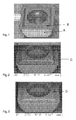
- Fig. 1 is light microscope photo showing that the (golden) top layer is intact at the clearance face (A) while it is fully removed on the rake face (B).
- Fig. 2 is an SEM back scattered electron micrograph showing that the second TIC x N y O z layer (light contrast) is exposed due to the removal of the alumina layer (dark contrast) at the area near the edge (C).
- Fig. 3 is an SEM micrograph using back scattered electrons showing that the second TIC x N y O z layer is exposed at most of the rake face (D).
- cemented carbide inserts of a substrate and a coating with excellent toughness properties particularly useful for toughness demanding short hole drilling, in general of steels the substrate comprising WC and 8-11 wt-% Co, preferably 9.5-10.5 wt-% Co and 0.2-0.5 wt-% Cr.
- the WC-grains have an average grain size of 0.5-1.5 ⁇ m.
- the cobalt binder phase is rather highly alloyed with W.
- the CW-value is a function of the W content in the Co binder phase. A CW-value of about 1 corresponds to a low W-content in the binder phase and a CW-value of about 0.75-0.8 correspond to a high W-content in the binder phase.
- the CW-ratio in inserts according to the present invention shall be 0.80-0.90.
- the coating comprises:
- the second TiC x N y O z layer at the rake face should be in the compressive stress state of from 0 to 2500 MPa, preferably 500-1500 MPa.
- the invention also relates to a method of making coated cemented carbide inserts with excellent toughness properties particularly useful for toughness demanding short hole drilling in general steels and stainless steels.
- the cemented carbide comprises WC and 8-11 wt-% Co, preferably 9.5-10.5 wt-% Co and 0.2-0.5 wt-% Cr.
- the WC-grains have an average grain size of 0.5-1.5 ⁇ m.
- the raw materials powders are wet milled to form a slurry with a pressing agent, small additions of carbon black or pure tungsten powder to obtain a CW-ratio in the sintered inserts of 0.80-0.90. After the wet milling, the slurry is dried to a powder, compacted and sintered. After conventional post sintering treatment a coating comprising:
- Inserts made of cemented carbide with composition WC + 10 wt-% Co, 0.39 wt% Cr and average WC grain size of 1.0 ⁇ m and a CW-ratio of 0.86 were coated with a 0.5 ⁇ m equiaxed TiC 0.05 N 0.95 -layer (with a high nitrogen content corresponding to an estimated C/N-ratio of 0.05) followed by a 4 ⁇ m thick TiC 0.54 N 0.46 -layer, with columnar grains using MTCVD-technique, temperature 885-850 °C and CH 3 CN as the carbon/nitrogen source.
- a 1.0 ⁇ m thick layer of Al 2 O 3 was deposited using a temperature of 970 °C and a concentration of H 2 S dopant of 0.4 % as disclosed in EP-A-523 021 .
- a 0.3 ⁇ m layer of TiN was deposited on top according to known CVD-technique. XRD-measurement showed that the Al 2 O 3 -layer consisted of 100 % K-phase.
- Inserts from example 1 were treated by wet blasting with a blasting pressure of 2.2 bar. As a result of the blasting treatment all the top TiN-layer and parts of the Al 2 O 3 -layer at the rake face was removed. At the rake face area at the edge line and 100 ⁇ m inwards, in the direction perpendicular to the edge line, most of the alumina was gone and as a result the second TiC 0.54 N 0.46 -layer was exposed at >80% of this surface area. At the clearance face most of the top TiN layer was still intact.
- the stress state in the second TiC 0.54 N 0.46 -layer was measured using X-ray diffraction. At the rake face the coating has compressive stress, -800 to -940 MPa. At the clearance face the stress state was tensile, +900 MPa.
- the method for evaluating the stress state of the second TiC 0.54 N 0.46 -layer in this and the following examples was according the well known sin 2 ⁇ method as described by I.C. Noyan, J.B. Cohen, Residual Stress Measurement by Diffraction and Interpretation, Springer-Verlag, New York, 1987 (pp 117-130 ).
- the stress evaluation was carried out by using ⁇ -geometry on a X-ray diffractometer Bruker D8 Discover-GADDS equipped with laser-video positioning, Euler 1/4-cradle, rotating anode as X-ray source (CuK ⁇ -radiation) and an area detector (Hi-star). A collimator of size 0.5 mm was used to focus the beam.
- Inserts from example 1 were treated with a blasting pressure of 2.4 and 2.6 bar respectively. As a result most of the alumina layer on the rake face was removed.
- the stress state in the second TiC 0.54 N 0.46 -layer was measured using X-ray diffraction. At the rake face the layer had compressive stress:
- the exposed second TiC 0.54 N 0.46 -layer was intact apart from some small dots ( ⁇ edge radius) at the very edge line.
- the example shows that high blasting pressure resulting in high compressive stresses can be applied without any major damages on the second TiC 0.54 N 0.46 -layer.
- Inserts from example 1 were treated by brushing of the edge line. The treatment resulted in a removal the top TIC x N y O z layer at the edge line as well as generating a smooth edge as disclosed in e.g. US 5,861,210 .
- Inserts from example 2 were tested and compared with inserts from Sandvik commercial grade GC4044 in a short hole drilling operation. The tested inserts were mechanically clamped on the periphery of the drill head. In the centre, inserts from Sandvik commercial grade GC1044 were used. Tool life criteria: crater wear, plastic deformation, flank wear, or chipping >0.25 mm.
- Drilled length at tool life A B C Inserts invention 20 meters >23 meters 22 meters Inserts reference tool failure after 13 meters 13 meters 15 meters
- Inserts from example 2 were tested and compared with inserts from Sandvik commercial grade 4044 in a short hole drilling operation. The tested inserts were mechanically clamped on the periphery of the drill head. In the center, inserts from Sandvik commercial grade 1044 were used. Tool life criteria: crater wear, plastic deformation, flank wear, or chipping >0.25 mm.
- Drilled length at tool life A B Inserts invention >25 meters 19 meters Inserts reference tool failure after 14 meters 13 meters
- Inserts from example 2 were tested and compared with inserts from Sandvik commercial grade 4044 in a short hole drilling operation. The tested inserts were mechanically clamped on the periphery of the drill head. In the center, inserts from Sandvik commercial grade 1044 were used. Tool life criteria: crater wear, plastic deformation, flank wear, or chipping >0.25 mm.
- Drilled length at tool life A B C Inserts invention 10 meters >16 meters >16 meters Inserts reference tool failure after 5 meters 7 meters 9 meters
- Inserts from example 2 were tested and compared with inserts from Sandvik commercial grades 4024 with respect to toughness in a short hole drilling operation. The tested inserts were mechanically clamped on the periphery of the drill head. In the center, inserts from Sandvik commercial grade 1044 were used. Tool life criteria: crater wear, plastic deformation, flank wear, or chipping >0.25 mm.
- Inserts from example 2 and example 4 were tested and compared with respect to toughness in a short hole drilling operation.
- the tested inserts were mechanically clamped on the periphery of the drill head.
- inserts from Sandvik commercial grade 1044 were used.
- Tool life criteria crater wear, plastic deformation, flank wear, or chipping >0.25 mm.
Landscapes
- Chemical & Material Sciences (AREA)
- Mechanical Engineering (AREA)
- Engineering & Computer Science (AREA)
- Organic Chemistry (AREA)
- Materials Engineering (AREA)
- Metallurgy (AREA)
- Chemical Kinetics & Catalysis (AREA)
- Inorganic Chemistry (AREA)
- General Chemical & Material Sciences (AREA)
- Chemical Vapour Deposition (AREA)
- Cutting Tools, Boring Holders, And Turrets (AREA)
- Drilling Tools (AREA)
- Powder Metallurgy (AREA)
Abstract
- a first (innermost) layer of TiCxNyOz with a thickness <1.5 µm,
- a layer of TiCxNyOz with a thickness of 1-8 µm with columnar grains,
- a layer of fine-grained grain κ-Al2O3 with a thickness of 0.5-5 µm and
- a further layer <1 µm thick of TiCxNyOz whereby at the rake face the outermost TiCxNyOz-layer and Al2O3-layer are fully or partly missing.
Description
- The present invention relates to a CVD coated cutting tool insert particularly useful for toughness demanding short hole drilling in general steel materials.
- Drilling in metals is divided generally in two types: long hole drilling and short hole drilling. By short hole drilling is meant generally drilling to a depth of up to 3-5 times the drill diameter.
- Long hole drilling puts large demands on good chip formation, lubrication, cooling and chip transport. This is achieved through specially developed drilling systems with specially designed drilling heads fastened to a drill rod and fulfilling the above mentioned demands.
- In short hole drilling, the demands are lower, enabling the use of simple helix drills formed either of solid cemented carbide or as solid tool steel or of tool steel provided with a number of cutting inserts of cemented carbide placed in such a way that they together form the necessary cutting edge. In the centre of the head, a tough grade of insert is sometimes used and on the periphery a more wear resistant one. The cutting inserts are brazed or mechanically clamped.
- The inserts are normally coated with a wear resistance coating. Two coating techniques are dominating: Physical Vapor Deposition (PVD) and Chemical Vapor Deposition (CVD).
-
WO 2006/080888 discloses PVD-coated cutting inserts with excellent toughness properties particularly useful for toughness demanding short hole drilling in low alloy and stainless steels. The inserts comprise a substrate and a coating. The substrate consists of WC with an average WC-grain size of 0.5-1.5 µm, 8-11 wt-% Co and 0.2-0.5 wt-% Cr with a coating of a laminar, multilayered structure of TiN+Ti1-xAlxN in polycrystalline, non-repetitive form deposited by arc evaporation technique. -
WO 2006/080889 discloses CVD-coated cutting inserts for short hole drilling in steel at high speed and moderate feed. The cemented carbide includes WC, 2-10 wt-% Co, and 4-12 wt-% cubic carbides of metals from groups IVa, Va or VIa. The Co-binder phase is highly alloyed with W with a CW-ratio of 0.75-0.90. The insert has a binder phase enriched and essentially cubic carbide free surface zone of a thickness of less than 20 µm. Along a line essentially bisecting the edge in the direction from the edge to the centre of the insert, a binder phase content increases essentially monotonously until it reaches the bulk composition. Binder phase content at the edge in vol-% is 0.65-0.75 times binder phase content of the bulk. The depth of the binder phase depletion is 100-300 µm. -
EP-A-1655390 discloses CVD-coated inserts particularly useful for milling under wet conditions. The inserts are characterised by a WC-Co cemented carbide substrate with a low content of cubic carbides and a coating including an inner layer of TICxNy with columnar grains followed by a layer of κ-Al2O3 and a top layer of TiN. - PVD-coatings improve the wear resistance but also improve the toughness. CVD-coatings show superior wear resistance in comparison to PVD-coatings but inferior toughness properties. Consequently, CVD-coated inserts are most commonly used in operations with high demands regarding wear resistance and PVD-coated inserts in operations with high toughness demands.
- The object of the present invention is to provide a CVD-coated cutting tool insert useful for toughness demanding short hole drilling in steel.
-
Fig. 1 is light microscope photo showing that the (golden) top layer is intact at the clearance face (A) while it is fully removed on the rake face (B). -
Fig. 2 is an SEM back scattered electron micrograph showing that the second TICxNyOz layer (light contrast) is exposed due to the removal of the alumina layer (dark contrast) at the area near the edge (C). -
Fig. 3 is an SEM micrograph using back scattered electrons showing that the second TICxNyOz layer is exposed at most of the rake face (D). - According to the invention, there is now provided cemented carbide inserts of a substrate and a coating with excellent toughness properties particularly useful for toughness demanding short hole drilling, in general of steels, the substrate comprising WC and 8-11 wt-% Co, preferably 9.5-10.5 wt-% Co and 0.2-0.5 wt-% Cr. The WC-grains have an average grain size of 0.5-1.5 µm.
- The cobalt binder phase is rather highly alloyed with W. The content of W in the binder phase is expressed as the

where magnetic-% Co is the weight percentage of magnetic Co and wt-% Co is the weight percentage of Co in the cemented carbide. The CW-value is a function of the W content in the Co binder phase. A CW-value of about 1 corresponds to a low W-content in the binder phase and a CW-value of about 0.75-0.8 correspond to a high W-content in the binder phase. The CW-ratio in inserts according to the present invention shall be 0.80-0.90. - The coating comprises:
- a first (innermost) layer of TiCxNyOz with x+y+z=1, preferably y>x and z<0.2, most preferably y>0.8 and z=0, with equiaxed grains with size <0.5 µm and a total thickness <1.5 µm, preferably >0.1 µm.
- a layer of TiCxNyOz with x+y+z=1, preferably with z=0, x>0.3 and y>0.3, most preferably x>0.5, with a thickness of 1-8 µm, preferably 2-7 µm, most preferably <6 µm, with columnar grains and with an average diameter of <5 µm, preferably 0.1-2 µm.
- a layer of a smooth, fine-grained, grain size about 0.5-2 µm, Al2O3 consisting essentially of the K-phase. However, the layer may contain small amounts, 1-3 vol-%, of the θ- or the α-phases as determined by XRD-measurement. The Al2O3-layer has a thickness of 0.5-5 µm, preferably 0.5-2 µm, and most preferably 0.5-1.5 µm. The Al2O3-layer is followed by a further layer, <1 µm, preferably 0.1-0.5 µm thick, of TiCxNyOz with x+y+z=1, preferably with y>x and z<0.3, most preferably y>0.8.The outermost TiCxNyOz-layer and the Al2O3-layer are fully or partly removed on 80% of the rake face surface area between the edge line and 100 µm inwards, in the direction perpendicular to the edge line.
- Furthermore, the second TiCxNyOz layer at the rake face should be in the compressive stress state of from 0 to 2500 MPa, preferably 500-1500 MPa.
- The invention also relates to a method of making coated cemented carbide inserts with excellent toughness properties particularly useful for toughness demanding short hole drilling in general steels and stainless steels. The cemented carbide comprises WC and 8-11 wt-% Co, preferably 9.5-10.5 wt-% Co and 0.2-0.5 wt-% Cr. The WC-grains have an average grain size of 0.5-1.5 µm. The raw materials powders are wet milled to form a slurry with a pressing agent, small additions of carbon black or pure tungsten powder to obtain a CW-ratio in the sintered inserts of 0.80-0.90. After the wet milling, the slurry is dried to a powder, compacted and sintered. After conventional post sintering treatment a coating comprising:
- a first (innermost) layer of TiCxNyOz with x+y+z=1, preferably y>x and z<0.2, most preferably y>0.8 and z=0, with equiaxed grains with size <0.5 µm and a total thickness <1.5 µm, preferably >0.1 µm, using known CVD-methods.
- a layer of TiCxNyOz with x+y+z=1, preferably with z=0, x>0.3 and y>0.3, most preferably x>0.5, with a thickness of 1-8 µm, preferably 2-7 µm, most preferably <6 µm, with columnar grains and with an average diameter of about <5 µm, preferably 0.1-2 µm, using preferably MTCVD-technique using acetonitrile as the carbon and nitrogen source for forming the layer in the temperature range of 700-900 °C. The exact conditions, however, depend to a certain extent on the design of the equipment used.
- a smooth Al2O3-layer consisting essentially of κ-Al2O3 is deposited under known conditions, such as disclosed in, e.g.,
EP-A-523 021 - Inserts made of cemented carbide with composition WC + 10 wt-% Co, 0.39 wt% Cr and average WC grain size of 1.0 µm and a CW-ratio of 0.86 were coated with a 0.5 µm equiaxed TiC0.05N0.95-layer (with a high nitrogen content corresponding to an estimated C/N-ratio of 0.05) followed by a 4 µm thick TiC0.54N0.46-layer, with columnar grains using MTCVD-technique, temperature 885-850 °C and CH3CN as the carbon/nitrogen source. In subsequent steps during the same coating cycle, a 1.0 µm thick layer of Al2O3 was deposited using a temperature of 970 °C and a concentration of H2S dopant of 0.4 % as disclosed in
EP-A-523 021 - Inserts from example 1 were treated by wet blasting with a blasting pressure of 2.2 bar. As a result of the blasting treatment all the top TiN-layer and parts of the Al2O3-layer at the rake face was removed. At the rake face area at the edge line and 100 µm inwards, in the direction perpendicular to the edge line, most of the alumina was gone and as a result the second TiC0.54N0.46-layer was exposed at >80% of this surface area. At the clearance face most of the top TiN layer was still intact.
- The stress state in the second TiC0.54N0.46-layer was measured using X-ray diffraction. At the rake face the coating has compressive stress, -800 to -940 MPa. At the clearance face the stress state was tensile, +900 MPa.
- The method for evaluating the stress state of the second TiC0.54N0.46-layer in this and the following examples was according the well known sin2ψ method as described by I.C. Noyan, J.B. Cohen, Residual Stress Measurement by Diffraction and Interpretation, Springer-Verlag, New York, 1987 (pp 117-130). The stress evaluation was carried out by using ψ-geometry on a X-ray diffractometer Bruker D8 Discover-GADDS equipped with laser-video positioning, Euler 1/4-cradle, rotating anode as X-ray source (CuKα-radiation) and an area detector (Hi-star). A collimator of size 0.5 mm was used to focus the beam. The analysis was performed on the TiCxNy (422) reflection using the goniometer settings 2θ=126°, ω=63° and Φ=0°, 90°, 180°, 270°. Eight ψ tilts between 0° and 70° were performed for each Φ-angle. The sin2ψ method was used to evaluate the residual stress using the software DIFFRACPlus Stress32 v. 1.04 from Bruker AXS with the constants Young's modulus, E=480 GPa and Poisson's ratio, V=0.20 and locating the reflection using the Pseudo-Voigt-Fit function. A biaxial stress state was confirmed and the average value was used as the residual stress value.
- Inserts from example 1 were treated with a blasting pressure of 2.4 and 2.6 bar respectively. As a result most of the alumina layer on the rake face was removed.
- The stress state in the second TiC0.54N0.46-layer was measured using X-ray diffraction. At the rake face the layer had compressive stress:
- 2.4 bar
- -1840 MPa
- 2.6 bar
- -2400 MPa
- 2.4 bar
- +850 MPa
- 2.6 bar
- +860 MPa
- The exposed second TiC0.54N0.46-layer was intact apart from some small dots (< edge radius) at the very edge line. The example shows that high blasting pressure resulting in high compressive stresses can be applied without any major damages on the second TiC0.54N0.46-layer.
- Inserts from example 1 were treated by brushing of the edge line. The treatment resulted in a removal the top TICxNyOz layer at the edge line as well as generating a smooth edge as disclosed in e.g.
US 5,861,210 . - Inserts from example 2 were tested and compared with inserts from Sandvik commercial grade GC4044 in a short hole drilling operation. The tested inserts were mechanically clamped on the periphery of the drill head. In the centre, inserts from Sandvik commercial grade GC1044 were used. Tool life criteria: crater wear, plastic deformation, flank wear, or chipping >0.25 mm.
- Material:
- Low alloy steel SS2541-03, 285 HB.
- Emulsion:
- Blasocut BC25, 8%.
- Operation:
- Through hole, 45 mm.
- Results. A surprisingly significant difference in tool life, regarding plastic deformation and flank wear resistance, was seen. The inserts according to the invention showed a much improved flank wear resistance compared to the reference.
- Drilled length at tool life:
A B C Inserts invention 20 meters >23 meters 22 meters Inserts reference tool failure after 13 meters 13 meters 15 meters - Inserts from example 2 were tested and compared with inserts from Sandvik commercial grade 4044 in a short hole drilling operation. The tested inserts were mechanically clamped on the periphery of the drill head. In the center, inserts from Sandvik commercial grade 1044 were used. Tool life criteria: crater wear, plastic deformation, flank wear, or chipping >0.25 mm.
- Material:
- Low alloy steel SS2541-03, 285 HB.
- Emulsion:
- Blasocut BC25, 8%.
- Operation:
- Through hole, 48 mm.
- Results. A surprisingly significant difference in tool life, regarding plastic deformation and flank wear resistance, was seen. The inserts according to the invention showed a much improved flank wear resistance compared to the reference.
- Drilled length at tool life:
A B Inserts invention >25 meters 19 meters Inserts reference tool failure after 14 meters 13 meters - Inserts from example 2 were tested and compared with inserts from Sandvik commercial grade 4044 in a short hole drilling operation. The tested inserts were mechanically clamped on the periphery of the drill head. In the center, inserts from Sandvik commercial grade 1044 were used. Tool life criteria: crater wear, plastic deformation, flank wear, or chipping >0.25 mm.
- Material:
- Stainless steel SS2343, 160 HB.
- Emulsion:
- Blasocut BC25, 8%.
- Operation:
- Through hole, 40 mm.
- Results. A surprisingly significant difference in tool life, regarding plastic deformation and flank wear resistance, was seen. The inserts according to the invention showed a much improved flank wear resistance compared to the inserts reference.
- Drilled length at tool life:
A B C Inserts invention 10 meters >16 meters >16 meters Inserts reference tool failure after 5 meters 7 meters 9 meters - Inserts from example 2 were tested and compared with inserts from Sandvik commercial grades 4024 with respect to toughness in a short hole drilling operation. The tested inserts were mechanically clamped on the periphery of the drill head. In the center, inserts from Sandvik commercial grade 1044 were used. Tool life criteria: crater wear, plastic deformation, flank wear, or chipping >0.25 mm.
- Material:
- Stainless steel SS2343, 160 HB.
- Emulsion:
- Blasocut BC25, 8%.
- Operation:
- Through hole, 50 mm.
- Cutting speed:
- 180 m/min
- Feed:
- 0.13 mm/r
- Drill:
-
Diameter 18 mm, 3XD - Insert style:
- CoroDrill 880-0303W06H-P, LM
- Results. An improvement in toughness behavior was seen. The inserts according to the invention showed a much improved toughness compared to the inserts reference.
- Drilled length at tool life:
- Inserts invention >20 meters
- Inserts reference tool failure after 17 meters
- Inserts from example 2 and example 4 were tested and compared with respect to toughness in a short hole drilling operation. The tested inserts were mechanically clamped on the periphery of the drill head. In the center, inserts from Sandvik commercial grade 1044 were used. Tool life criteria: crater wear, plastic deformation, flank wear, or chipping >0.25 mm.
- Material:
- Low alloy steel SS2541-03, 285 HB.
- Emulsion:
- Blasocut BC25, 8%.
- Operation:
- Through hole, 45 mm.
- Cutting speed:
- 240 m/min
- Feed:
- 0.10 mm/r
- Drill:
-
Diameter 15 mm, 3xD - Insert style:
- CoroDrill 880-0202W05H-P, GR
- Results. A significant difference in toughness behavior was seen. The insert from example 2 got controlled flank wear whilst the insert from example 4 failed due to occurrence of a big crack penetrating half of the insert together with edge breakage adjacent to the crack.
Drilled length at tool life: - Inserts invention 20 meters
- Inserts example 4 tool failure after 9 meters
| A | B | C | |
| Cutting speed: | 200 m/min | 180 m/min | 160 m/min |
| Feed: | 0.12 mm/r | 0.13 mm/r | 0.15 mm/r |
| Drill: | | ||
| Insert style: | CoroDrill 880-0202W05H-P, GR | ||
| A | B | |
| Cutting speed: | 170 m/min | 195 m/min |
| Feed: | 0.15 mm/r | 0.13 mm/r |
| Drill: | | |
| Insert style: | CoroDrill 880-0303W06H-P, GR | |
| A | B | C | |
| Cutting speed: | 240 m/min | 220 m/min | 200/m/min |
| Feed: | 0.10 mm/r | 0.10 mm/r | 0,11 mm/r |
| Drill: | | ||
| Insert style: | CoroDrill 880-0202W05H-P, LM | ||
Claims (3)
- Cemented carbide inserts comprising a substrate and a coating with excellent toughness properties particularly useful for toughness demanding short hole drilling in general steels
characterised in the substrate comprising WC having an average grain size of 0.5-1.5 µm and 8-11 wt-% Co, preferably 9.5-10.5 wt-% Co, and 0.2-0.5 wt-% Cr whereby the cobalt binder phase has a CW-ratio of 0.80-0.90 and the coating comprising- a first, innermost layer of TiCxNyOz with x+y+z=1, preferably y>x and z<0.2, most preferably y>0.8 and z=0, with equiaxed grains of a size <0.5 µm and a total thickness <1.5 µm, preferably >0.1 µm,- a layer of TiCxNyOz with x+y+z=1, preferably with z=0, x>0.3 and y>0.3, most preferably x>0.5, with a thickness of 1-8 µm, preferably 2-7 µm, most preferably <6 µm, with columnar grains and with an average diameter of <5 µm, preferably 0.1-2 µm,- a layer of smooth, fine-grained, grain size about 0.5-2 µm Al2O3 consisting essentially of the K-phase with a thickness of 0.5-5 µm, preferably 0.5-2 µm, and- a further layer <1 µm thick, preferably 0.1-0.5 µm thick, of TICxNyOz with x+y+z=1, preferably with y>x and z<0.3 whereby at the rake face the outermost TiCxNyOz-layer and Al2O3-layer are fully or partly missing on 80% of the rake face surface area between the edge line and 100 µm inwards, in the direction perpendicular to the edge line. - Cemented carbide insert according to claim 1
characterised in that the second TiCxNyOz layer at the rake face has a compressive stress state of from 0 to 2500 MPa, preferably from 500 to 1500 MPa. - Method of making coated cemented carbide inserts with excellent toughness properties particularly useful for toughness demanding short hole drilling in general steels
characterised in providing a cemented carbide substrate comprising WC having an average grain size of 0.5-1.5 µm, 8-11 wt-% Co, preferably 9.5-10.5 wt-% Co and 0.2-0.5 wt-% Cr by wetmilling powders with pressing agent, and small additions of carbon black or pure tungsten powder to obtain a CW-ratio in the sintered inserts of 0.80-0.90, in a slurry, drying the slurry to a powder, compacting and sintering and after conventional post sintering treatment depositing a coating comprising- a first, innermost layer of TiCxNyOz with x+y+z=1, preferably y>x and z<0.2, most preferably y>0.8 and z=0, with equiaxed grains with size <0.5 µm and a total thickness <1.5 µm, preferably >0.1 µm, using known CVD-methods,- a layer of TICxNyOz with x+y+z=1, preferably with z=0, x>0.3 and y>0.3, most preferably x>0.5, with a thickness of 1-8 µm, preferably 2-7 µm, most preferably <6 µm, with columnar grains and with an average diameter of about <5 µm, preferably 0.1-2 µm, using preferably MTCVD-technique with acetonitrile as the carbon and nitrogen source for forming the layer in the temperature range of 700-900 °C,- a layer of smooth fine-grained grain size about 0.5-2 µm Al2O3 consisting essentially of the K-phase with a thickness of 0.5-5 µm, preferably 0.5-2 µm, using known CVD-methods,- a further layer <1 µm, preferably 0.1-0.5 µm thick, of TICxNyOz with x+y+z=1, preferably with y>x and z<0.3, using known CVD-methods,- fully or partly removing the outermost TiCxNyOz-layer and Al2O3-layer on at least 80 % of the rake face surface area between the edge line and 100 µm inwards in the direction perpendicular to the edge line by wet blasting the coated surface with fine-grained, 400-150 mesh, alumina powder.
Applications Claiming Priority (1)
| Application Number | Priority Date | Filing Date | Title |
|---|---|---|---|
| SE0602812A SE0602812L (en) | 2006-12-27 | 2006-12-27 | CVD coated cemented carbide inserts for toughness requiring short hole drilling operations |
Publications (1)
| Publication Number | Publication Date |
|---|---|
| EP1944391A1 true EP1944391A1 (en) | 2008-07-16 |
Family
ID=39272093
Family Applications (1)
| Application Number | Title | Priority Date | Filing Date |
|---|---|---|---|
| EP07121947A Withdrawn EP1944391A1 (en) | 2006-12-27 | 2007-11-30 | CVD coated cemented carbide insert for toughness demanding short hole drilling operations |
Country Status (6)
| Country | Link |
|---|---|
| US (1) | US20080166527A1 (en) |
| EP (1) | EP1944391A1 (en) |
| JP (1) | JP2008207317A (en) |
| KR (1) | KR20080061313A (en) |
| CN (1) | CN101219591A (en) |
| SE (1) | SE0602812L (en) |
Cited By (2)
| Publication number | Priority date | Publication date | Assignee | Title |
|---|---|---|---|---|
| KR100397163B1 (en) * | 1999-08-03 | 2003-09-06 | 에스엠시 가부시키가이샤 | Input-output unit for serial-parallel signal conversion |
| CN101941085A (en) * | 2009-07-03 | 2011-01-12 | 山特维克知识产权股份有限公司 | The cutting tool insert of band coating |
Families Citing this family (8)
| Publication number | Priority date | Publication date | Assignee | Title |
|---|---|---|---|---|
| JP5462549B2 (en) * | 2009-08-20 | 2014-04-02 | 住友電気工業株式会社 | Cemented carbide |
| RU2545858C1 (en) * | 2013-12-26 | 2015-04-10 | Открытое акционерное общество Производственное объединение "Стрела" | Method of reinforcement coating application |
| US10895001B2 (en) * | 2015-03-26 | 2021-01-19 | Sandvik Intellectual Property Ab | Rock drill button |
| JP6955549B2 (en) * | 2017-03-29 | 2021-10-27 | 京セラ株式会社 | Cutting inserts and cutting tools equipped with them |
| US12109625B2 (en) * | 2018-09-28 | 2024-10-08 | Mitsubishi Materials Corporation | Surface-coated TiN-based cermet cutting tool in which hard coating layer exhibits excellent chipping resistance |
| KR102450097B1 (en) * | 2020-11-16 | 2022-10-05 | 한국야금 주식회사 | Hard film for cutting tools |
| CN114457222B (en) * | 2021-09-30 | 2023-07-14 | 中国船舶重工集团公司第七一八研究所 | Method for improving processability of high-purity tungsten |
| CN117305806B (en) * | 2023-11-29 | 2024-03-08 | 赣州澳克泰工具技术有限公司 | Coated cutting insert and method of making same |
Citations (11)
| Publication number | Priority date | Publication date | Assignee | Title |
|---|---|---|---|---|
| EP0523021A1 (en) | 1991-06-25 | 1993-01-13 | Sandvik Aktiebolag | Method of manufacturing an alumina coated sintered body |
| EP0683244A2 (en) * | 1994-04-27 | 1995-11-22 | Sumitomo Electric Industries, Ltd. | Coated hard alloy tool |
| US5861210A (en) | 1994-07-20 | 1999-01-19 | Sandvik Ab | Aluminum oxide coated tool |
| EP1038989A2 (en) * | 1999-03-26 | 2000-09-27 | Sandvik Aktiebolag | Coated milling insert |
| WO2001016389A1 (en) * | 1999-09-01 | 2001-03-08 | Sandvik Ab; (Publ) | Coated milling insert |
| EP1205569A2 (en) * | 2000-11-08 | 2002-05-15 | Sandvik Aktiebolag | Coated inserts for rough milling |
| EP1563933A1 (en) * | 2004-02-17 | 2005-08-17 | Sandvik Intellectual Property HB | Cutting tool for bimetal machining |
| EP1655390A1 (en) | 2004-11-08 | 2006-05-10 | Sandvik Intellectual Property AB | Coated inserts for wet milling |
| WO2006080888A1 (en) | 2005-01-31 | 2006-08-03 | Sandvik Intellectual Property Ab | Cemented carbide insert for toughness demanding short hole drilling operations |
| WO2006080889A1 (en) | 2005-01-31 | 2006-08-03 | Sandvik Intellectual Property Ab | Cemented carbide insert for wear resistance demanding short hole drilling operations |
| EP1803835A1 (en) * | 2005-12-30 | 2007-07-04 | Sandvik Intellectual Property AB | Coated cutting tool insert |
Family Cites Families (4)
| Publication number | Priority date | Publication date | Assignee | Title |
|---|---|---|---|---|
| JP3061041B2 (en) * | 1998-01-22 | 2000-07-10 | 住友電気工業株式会社 | Coated cemented carbide tool |
| JPH11229143A (en) * | 1998-02-20 | 1999-08-24 | Mitsubishi Materials Corp | Surface-coated cemented carbide end mill with excellent fracture resistance |
| SE519106C2 (en) * | 1999-04-06 | 2003-01-14 | Sandvik Ab | Ways to manufacture submicron cemented carbide with increased toughness |
| EP1609883B1 (en) * | 2004-06-24 | 2017-09-20 | Sandvik Intellectual Property AB | Coated metal cutting tool |
-
2006
- 2006-12-27 SE SE0602812A patent/SE0602812L/en not_active Application Discontinuation
-
2007
- 2007-11-30 EP EP07121947A patent/EP1944391A1/en not_active Withdrawn
- 2007-12-20 US US12/003,198 patent/US20080166527A1/en not_active Abandoned
- 2007-12-26 JP JP2007334861A patent/JP2008207317A/en active Pending
- 2007-12-26 KR KR1020070137978A patent/KR20080061313A/en not_active Withdrawn
- 2007-12-27 CN CNA2007101606004A patent/CN101219591A/en active Pending
Patent Citations (11)
| Publication number | Priority date | Publication date | Assignee | Title |
|---|---|---|---|---|
| EP0523021A1 (en) | 1991-06-25 | 1993-01-13 | Sandvik Aktiebolag | Method of manufacturing an alumina coated sintered body |
| EP0683244A2 (en) * | 1994-04-27 | 1995-11-22 | Sumitomo Electric Industries, Ltd. | Coated hard alloy tool |
| US5861210A (en) | 1994-07-20 | 1999-01-19 | Sandvik Ab | Aluminum oxide coated tool |
| EP1038989A2 (en) * | 1999-03-26 | 2000-09-27 | Sandvik Aktiebolag | Coated milling insert |
| WO2001016389A1 (en) * | 1999-09-01 | 2001-03-08 | Sandvik Ab; (Publ) | Coated milling insert |
| EP1205569A2 (en) * | 2000-11-08 | 2002-05-15 | Sandvik Aktiebolag | Coated inserts for rough milling |
| EP1563933A1 (en) * | 2004-02-17 | 2005-08-17 | Sandvik Intellectual Property HB | Cutting tool for bimetal machining |
| EP1655390A1 (en) | 2004-11-08 | 2006-05-10 | Sandvik Intellectual Property AB | Coated inserts for wet milling |
| WO2006080888A1 (en) | 2005-01-31 | 2006-08-03 | Sandvik Intellectual Property Ab | Cemented carbide insert for toughness demanding short hole drilling operations |
| WO2006080889A1 (en) | 2005-01-31 | 2006-08-03 | Sandvik Intellectual Property Ab | Cemented carbide insert for wear resistance demanding short hole drilling operations |
| EP1803835A1 (en) * | 2005-12-30 | 2007-07-04 | Sandvik Intellectual Property AB | Coated cutting tool insert |
Non-Patent Citations (1)
| Title |
|---|
| I.C. NOYAN; J.B. COHEN: "Residual Stress Measurement by Diffraction and Interpretation", 1987, SPRINGER-VERLAG, pages: 117 - 130 |
Cited By (5)
| Publication number | Priority date | Publication date | Assignee | Title |
|---|---|---|---|---|
| KR100397163B1 (en) * | 1999-08-03 | 2003-09-06 | 에스엠시 가부시키가이샤 | Input-output unit for serial-parallel signal conversion |
| CN101941085A (en) * | 2009-07-03 | 2011-01-12 | 山特维克知识产权股份有限公司 | The cutting tool insert of band coating |
| EP2287359A1 (en) * | 2009-07-03 | 2011-02-23 | Sandvik Intellectual Property AB | Coated cutting tool insert |
| CN101941085B (en) * | 2009-07-03 | 2015-05-13 | 山特维克知识产权股份有限公司 | Coated cutting tool insert |
| US9109290B2 (en) | 2009-07-03 | 2015-08-18 | Sandvik Intellectual Property Ab | Coated cutting tool insert |
Also Published As
| Publication number | Publication date |
|---|---|
| KR20080061313A (en) | 2008-07-02 |
| US20080166527A1 (en) | 2008-07-10 |
| CN101219591A (en) | 2008-07-16 |
| SE0602812L (en) | 2008-06-28 |
| JP2008207317A (en) | 2008-09-11 |
Similar Documents
| Publication | Publication Date | Title |
|---|---|---|
| US20080166527A1 (en) | CVD-coated cemented carbide insert for toughness demanding short hole drilling operations | |
| EP2791387B1 (en) | Method of manufacturing a coated cutting tool. | |
| US5945207A (en) | Coated cutting insert | |
| US6221479B1 (en) | Cemented carbide insert for turning, milling and drilling | |
| US20060286410A1 (en) | Cemented carbide insert for toughness demanding short hole drilling operations | |
| EP2006040B1 (en) | Cutting tool, method for producing same and cutting method | |
| EP1528125A2 (en) | Coated cutting insert for rough turning | |
| EP2287359B1 (en) | Coated cutting tool insert | |
| EP1100979B1 (en) | Coated grooving or parting insert | |
| WO1997020083A1 (en) | Coated cutting insert and method of making it | |
| EP3456858B1 (en) | Coated cutting tool | |
| US20080298921A1 (en) | Coated cutting tool insert | |
| EP2459771A1 (en) | Coated cutting tool insert for turning of steels | |
| US8053063B2 (en) | Coated cutting insert for milling applications | |
| US8142848B2 (en) | Coated cutting insert for milling | |
| US7150772B2 (en) | CVD coated cutting tool insert | |
| JP5088481B2 (en) | Surface coated cutting tool with excellent wear resistance with hard coating layer in heavy cutting | |
| US20070160843A1 (en) | Coated cemented carbide inserts | |
| US20060188748A1 (en) | Cemented carbide insert for wear resistance demanding short hole drilling operations | |
| US20070160844A1 (en) | Coated inserts | |
| USRE40005E1 (en) | Coated cutting insert | |
| JPH0919807A (en) | Surface-coated WC-based cemented carbide cutting tool | |
| JP2007186743A (en) | Member coated with multilayered film |
Legal Events
| Date | Code | Title | Description |
|---|---|---|---|
| PUAI | Public reference made under article 153(3) epc to a published international application that has entered the european phase |
Free format text: ORIGINAL CODE: 0009012 |
|
| AK | Designated contracting states |
Kind code of ref document: A1 Designated state(s): AT BE BG CH CY CZ DE DK EE ES FI FR GB GR HU IE IS IT LI LT LU LV MC MT NL PL PT RO SE SI SK TR |
|
| AX | Request for extension of the european patent |
Extension state: AL BA HR MK RS |
|
| 17P | Request for examination filed |
Effective date: 20090116 |
|
| 17Q | First examination report despatched |
Effective date: 20090223 |
|
| AKX | Designation fees paid |
Designated state(s): AT BE BG CH CY CZ DE DK EE ES FI FR GB GR HU IE IS IT LI LT LU LV MC MT NL PL PT RO SE SI SK TR |
|
| STAA | Information on the status of an ep patent application or granted ep patent |
Free format text: STATUS: THE APPLICATION IS DEEMED TO BE WITHDRAWN |
|
| 18D | Application deemed to be withdrawn |
Effective date: 20090908 |