EP1944207A1 - Pretensioner and seat belt device - Google Patents
Pretensioner and seat belt device Download PDFInfo
- Publication number
- EP1944207A1 EP1944207A1 EP06822788A EP06822788A EP1944207A1 EP 1944207 A1 EP1944207 A1 EP 1944207A1 EP 06822788 A EP06822788 A EP 06822788A EP 06822788 A EP06822788 A EP 06822788A EP 1944207 A1 EP1944207 A1 EP 1944207A1
- Authority
- EP
- European Patent Office
- Prior art keywords
- wire
- seat belt
- housing
- piston
- agent
- Prior art date
- Legal status (The legal status is an assumption and is not a legal conclusion. Google has not performed a legal analysis and makes no representation as to the accuracy of the status listed.)
- Withdrawn
Links
- 239000003795 chemical substances by application Substances 0.000 claims description 35
- 238000004804 winding Methods 0.000 claims description 10
- 230000000452 restraining effect Effects 0.000 claims description 8
- 229920001651 Cyanoacrylate Polymers 0.000 claims description 4
- 239000004593 Epoxy Substances 0.000 claims description 4
- MWCLLHOVUTZFKS-UHFFFAOYSA-N Methyl cyanoacrylate Chemical compound COC(=O)C(=C)C#N MWCLLHOVUTZFKS-UHFFFAOYSA-N 0.000 claims description 4
- 229920001296 polysiloxane Polymers 0.000 claims description 4
- 238000004519 manufacturing process Methods 0.000 abstract description 7
- 238000007789 sealing Methods 0.000 abstract description 4
- 230000007423 decrease Effects 0.000 description 2
- 230000000694 effects Effects 0.000 description 2
- 239000000654 additive Substances 0.000 description 1
- 239000000853 adhesive Substances 0.000 description 1
- 230000001070 adhesive effect Effects 0.000 description 1
- 239000011248 coating agent Substances 0.000 description 1
- 238000001514 detection method Methods 0.000 description 1
- 229920001971 elastomer Polymers 0.000 description 1
- 239000000463 material Substances 0.000 description 1
- 239000002184 metal Substances 0.000 description 1
- 238000012986 modification Methods 0.000 description 1
- 230000004048 modification Effects 0.000 description 1
- 238000012856 packing Methods 0.000 description 1
- 239000005060 rubber Substances 0.000 description 1
- 229920003051 synthetic elastomer Polymers 0.000 description 1
- 229920003002 synthetic resin Polymers 0.000 description 1
- 239000000057 synthetic resin Substances 0.000 description 1
- 239000005061 synthetic rubber Substances 0.000 description 1
Images


Classifications
-
- B—PERFORMING OPERATIONS; TRANSPORTING
- B60—VEHICLES IN GENERAL
- B60R—VEHICLES, VEHICLE FITTINGS, OR VEHICLE PARTS, NOT OTHERWISE PROVIDED FOR
- B60R22/00—Safety belts or body harnesses in vehicles
- B60R22/18—Anchoring devices
- B60R22/195—Anchoring devices with means to tension the belt in an emergency, e.g. means of the through-anchor or splitted reel type
- B60R22/1952—Transmission of tensioning power by cable; Return motion locking means therefor
-
- B—PERFORMING OPERATIONS; TRANSPORTING
- B60—VEHICLES IN GENERAL
- B60R—VEHICLES, VEHICLE FITTINGS, OR VEHICLE PARTS, NOT OTHERWISE PROVIDED FOR
- B60R22/00—Safety belts or body harnesses in vehicles
- B60R22/18—Anchoring devices
- B60R22/195—Anchoring devices with means to tension the belt in an emergency, e.g. means of the through-anchor or splitted reel type
- B60R22/1954—Anchoring devices with means to tension the belt in an emergency, e.g. means of the through-anchor or splitted reel type characterised by fluid actuators, e.g. pyrotechnic gas generators
- B60R22/1955—Linear actuators
Definitions
- the present invention relates to a pretensioner and a seat belt apparatus which retracts a seat belt buckle at the time of a rapid deceleration of a vehicle so as to restrain an occupant with a seat belt.
- a seat belt apparatus for restraining occupants each of which prevents the occupant from being thrown forward due to an inertial force when an impact is generated, for example, at the time of a rapid deceleration or a collision of the vehicle.
- a seat belt apparatus is generally provided with an Emergency Locking Retractor (hereinafter, referred to as an ELR) which does not restrain motion of the occupant in normal driving but locks a winding shaft for the seat belt to prevent the seat belt from being further withdrawn only when an impact is generated to the vehicle.
- the ELR locks the winding shaft within a very short time after detecting a deceleration equal to or higher than a predetermined value, thereby preventing the seat belt from being further withdrawn.
- the pretensioner as disclosed in Patent document 1 comprises a wire of which one end is connected to a seat belt buckle and the other end is fixed to a piston in a cylinder and a housing through which the wire is passed and which supports the cylinder. According to this pretensioner, when a deceleration of the vehicle is detected, high-pressure gas is spouted into a gas chamber formed in the housing so as to move the piston, thereby retracting the wire. In the gas chamber of the housing, a guide pipe is disposed to protect the wire from the high-pressure gas. In the housing, a packing for sealing a clearance between the wire and the housing is disposed adjacent to the guide pipe.
- Patent document 1 JP-A-2003-146184 ( Fig. 2 and Fig. 4 ).
- the object of the present invention is to provide a pretensioner and a seat belt apparatus capable of projecting a wire without leading to increase in manufacturing cost.
- the first invention is a pretensioner for restraining an occupant with a seat belt by retracting a seat belt buckle at the time of generation of an impact to a vehicle, comprising: a wire of which one end is connected to said seat belt buckle; a piston which is connected to the other end of said wire; a cylinder which accommodates said piston therein such that said piston is slidable; a housing through which said wire is passed and which supports said cylinder; a gas supply unit which supplies gas, for moving said piston in a direction of retracting said wire, into said cylinder through said housing; and a seal member which is disposed inside said housing to seal a clearance between said wire and the inner wall of said housing, and is characterized in that an agent for improving the heat resistance is applied to said wire.
- gas for moving the piston (hereinafter, referred to as high-pressure gas) is spouted out from the gas supply unit at the time of generation of an impact to a vehicle.
- the high-pressure gas is supplied to the cylinder through the inside of the housing. Then, the piston is moved by the high-pressure gas to retract the wire, thereby retracting the seat belt buckle.
- the wire Since the heat resistance of the wire is improved by applying the aforementioned agent to the wire, the wire is protected even if the high-pressure gas spouted out from the gas supply unit into the housing collides with the wire. This can eliminate the need for separately preparing a guide pipe as the prior art, thereby reducing the number of parts, solving the problem of complication of assembly, and thus reducing the manufacturing cost.
- the second invention is characterized in that, in the aforementioned first invention, said agent is applied to at least a portion, positioned inside said housing, of said wire.
- the agent is applied to a portion inside the housing where can be exposed to the high-pressure gas from the gas supply unit, it is possible to protect the wire from the high-pressure gas.
- the third invention is characterized in that, in the aforementioned second invention, said agent is applied to at least a portion, positioned between said seal member and said piston, of said wire positioned within said housing.
- the agent is applied to a portion between the seal member and the piston within the housing where is easily exposed to the high-pressure gas from the gas supply unit, it is possible to protect the wire from the high-pressure gas.
- the fourth invention is characterized in that, in any of the aforementioned first through third inventions, said agent is at least one of a group consisting of cyanoacrylate agent, silicone agent, and epoxy agent.
- the fifth invention is a seat belt apparatus comprising: a seat belt; a retractor for winding up said seat belt; a tongue attached to said seat belt; a seat belt buckle with which said tongue is detachably latched; and a pretensioner for restraining an occupant with said seat belt by retracting said seat belt buckle at the time of generation of an impact to a vehicle
- said pretensioner comprises: a wire of which one end is connected to said seat belt buckle; a piston which is connected to the other end of said wire; a cylinder which accommodates said piston therein such that said piston is slidable; a housing through which said wire is passed and which supports said cylinder; a gas supply unit which supplies gas, for moving said piston in a direction of retracting said wire, into said cylinder through said housing; and a seal member which is disposed inside said housing to seal a clearance between said wire and the inner wall of said housing, and is characterized in that an agent for improving the heat resistance is applied to said wire.
- the aforementioned pretensioner is provided, thereby reducing the number of parts of the pretensioner, solving the problem of complication of assembly, and thus reducing the manufacturing cost.
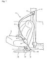
- Fig. 1 is a perspective view showing a seat belt apparatus with a pretensioner of the embodiment according to the present invention.
- the seat belt apparatus 1 comprises a seat belt 3 for restraining an occupant which can be withdrawn from a retractor 2.
- the retractor 2 is a device for winding up the seat belt 3 and is fixed to a lower portion of a center pillar 4 in a cabin of a vehicle (an automobile in this example).
- the seat belt 3 withdrawn from the retractor 2 to extend toward an upper portion of the vehicle passes through a through ring 5 and is bent at the through ring 5 to extend toward a lower portion of the vehicle.
- the distal end of the seat belt 3 is fixed to an anchor plate 7 which is disposed between the center pillar 4 and a seat 6.
- a tongue 8 is attached to the seat belt 3 such that the seat belt 3 passes through the tongue 8.
- the tongue 8 can be latched with a seat belt buckle 9 which is disposed on a side opposite to the anchor plate 7 relative to the seat 6.
- the pretensioner 10 of this embodiment is mounted to the seat belt buckle 9.
- the pretensioner 10 is a device for retracting the seat belt buckle 9 when an impact is generated, for example, at the time of a sudden stop or a collision of the vehicle, thereby restraining the occupant with the seat belt 3.
- the pretensioner 10 comprises a wire 11 connected to the seat belt buckle 9, a housing 12 which is fixed to, for example, a vehicle body directly or via brackets (not shown) and through which the wire 11 is inserted, a holder 13 which is attached to one side of the housing 12 and has a guide portion 13a (see Fig. 2 ) for guiding the wire 11 such that a portion of the wire 11 is bent, and a cylinder 14 which is attached to the other side of the housing 12.
- Fig. 2 is a vertical sectional view of the pretensioner 10.
- one end of the wire 11 is connected to the seat belt buckle 9 (see Fig. 1 ) and the other end of the wire 11 is connected to the piston 15.
- the piston 15 is slidably accommodated in the cylinder 14.
- the piston 15 comprises a piston main body 16 through which the wire 11 is inserted, and a wire holding portion 17 which is connected to an end of the piston main body 16 and fixes the other end of the wire 11.
- the piston main body 16 is provided with an annular groove 18 in which an O-ring 19 for sealing a clearance between the piston main body 16 and an inner wall of the cylinder 14 is disposed.
- the piston main body 16 has a tapered portion 20 which is formed on the distal end side (on the side of the wire holding portion 17) relative to the annular groove 18 and gradually increases in diameter toward the distal end side. Between the tapered portion 20 and the inner wall of the cylinder 14, a ball ring 21 and a plurality of balls 22 are arranged. This arrangement allows the piston 15 to move in a direction toward the distal end (direction A) and prevents the piston 15 from moving in a direction toward the proximal end (direction B).
- the housing 12 for supporting the cylinder 14 is provided with a gas generator 23 which generates high-pressure gas for moving the piston 15 in the direction A.
- the gas generator 23 has a gas generating section and an ignition section which are not shown. As a rapid deceleration of the vehicle is detected by, for example, a sensor (not shown), an ignition signal is transmitted to the ignition section so that the ignition section is activated and the gas generating section spouts out high-temperature high-pressure gas.
- a gas passage 24 for supplying the high-pressure gas spouted from the gas generator 23 to the cylinder 14 and a seal receiving portion 25 which gradually decreases in diameter toward the holder 13 are formed inside the housing 12.
- the gas passage 24 is formed between the cylinder 14 and the seal receiving portion 25 in the housing 12.
- a seal member 30 for sealing a clearance between the wire 11 and the inner wall of the housing 12.
- the seal member 30 has a tapered shape which gradually decreases in diameter toward the holder 13 corresponding to the diameter of the seal receiving portion 25 as shown in Figs. 2 and 3 .
- the seal member 30 is made of, for example, a rubber material (such as a synthetic rubber containing additives), a synthetic resin, or a metal having elasticity.
- the inner diameter of the through hole 28 of the seal member 30 is slightly larger than the outer diameter of the wire 11 such that the wire 11 is slidable relative to the seal member 30.
- the wire 11 is disposed to pass a radial center of the gas passage 24 in the axial direction.
- the region shown by X in Fig. 2 of the wire 11 at least positioned within the gas passage 24 (for example, between the piston 15 and the seal member 30) is an agent applied portion 11A on which a predetermined agent for improving the heat resistance of the wire 11 is previously applied (including a state where the wire is dipped in an impregnating bath so that the wire is impregnated with the agent and a state where the agent component is supplied and bonded to the wire as well as a state where the wire is daubed with the agent).
- the agent applied portion 11A may extend a wider region along the axial direction of the wire including, for example, an area positioned inside the seal member 30 and an area positioned inside the piston main body 16 (or the wire holding portion 17) in addition to the region shown by X.
- the entire area of the wire 11 positioned inside the housing 12 and the entire area positioned inside the cylinder 14 may be the agent applied portion 11A.
- an agent containing at least one of a group consisting of cyanoacrylate, silicone, and epoxy may be used.
- an agent which is known in the art to be used as a coating agent or adhesive and contributes to improvement of the heat resistance of the wire 11 may be used.
- the gas generator 23 and the gas passage 24 compose a gas supplying device as claimed in claims.
- the seal member 30 is pushed toward the seal receiving portion 25 by the high-pressure gas within the gas passage 24 so that the seal member 30 is kept in close contact with the seal receiving portion 25 as shown in Fig. 4 .
- the wire 11 is displaced sliding relative to the seal member 30.
- the wire 11 since the heat resistance of the wire 11 is improved by applying the aforementioned agent to the wire 11, the wire 11 is protected even if the high-pressure gas spouted out from the gas generator 23 into the housing 12 as mentioned above collides with the wire 11. This can eliminate the need for separately preparing a guide pipe as the prior art, thereby reducing the number of parts, solving the problem of complication of assembly, and thus reducing the manufacturing cost.
- the present invention is not limited to the aforementioned structure, various modifications and variations can be made without departing from the technical spirit of the invention.
- the configuration of the seal member 30 is a tapered shape in the aforementioned embodiment, the configuration of the seal member is not limited thereto and may be a cylindrical shape of which outer diameter is entirely uniform in the axial direction.
- the present invention is not limited thereto and can be applied to any vehicle provided with a seat belt for restraining an occupant to a seat or a predetermined position, for example, vehicles including rail vehicles such as a train, a bullet train, and a monorail, boats including a hovercraft and a hydrofoil craft, and other transport facilities, and further a vehicle installed at an amusement park as an amusement park ride, and a business or general elevator machine installed in a building.
- a seat belt for restraining an occupant to a seat or a predetermined position
- vehicles including rail vehicles such as a train, a bullet train, and a monorail, boats including a hovercraft and a hydrofoil craft, and other transport facilities, and further a vehicle installed at an amusement park as an amusement park ride, and a business or general elevator machine installed in a building.
Landscapes
- Engineering & Computer Science (AREA)
- Mechanical Engineering (AREA)
- Automotive Seat Belt Assembly (AREA)
Abstract
[PROBLEMS] To protect a wire without increasing the manufacturing cost.
[MEANS FOR SOLVING THE PROBLEMS] A pretensioner 10 comprises a housing 12 through which the wire 11 is passed and a cylinder 14 supported to the housing 12. One end of the wire 11 is connected to a seat belt buckle, and the other end of the wire 11 is connected to a piston 15 slidably received in the cylinder 14. A gas generator 23 for generating a high-pressure gas for moving the piston 15 in the direction of retracting the wire 11 is provided on the housing 12. Furthermore, a seal member 30 for sealing a clearance between the wire 11 and the inner wall of the housing 12 is provided in the housing 12. An agent for improving heat resistance is applied onto an agent applied portion 11A of the wire 11 positioned within a gas passage 24.
Description
- The present invention relates to a pretensioner and a seat belt apparatus which retracts a seat belt buckle at the time of a rapid deceleration of a vehicle so as to restrain an occupant with a seat belt.
- Conventionally, vehicles are equipped with seat belt apparatuses for restraining occupants each of which prevents the occupant from being thrown forward due to an inertial force when an impact is generated, for example, at the time of a rapid deceleration or a collision of the vehicle. Such a seat belt apparatus is generally provided with an Emergency Locking Retractor (hereinafter, referred to as an ELR) which does not restrain motion of the occupant in normal driving but locks a winding shaft for the seat belt to prevent the seat belt from being further withdrawn only when an impact is generated to the vehicle. The ELR locks the winding shaft within a very short time after detecting a deceleration equal to or higher than a predetermined value, thereby preventing the seat belt from being further withdrawn.
- However, according to the aforementioned ELR which merely locks the winding shaft, in case where the seat belt is loosely wound onto the winding shaft when worn by the occupant, a certain amount of the seat belt may be withdrawn even when the winding shaft is locked. Even when the seat belt is not loosely wound, the seat belt may still be withdrawn between the time of detection of a deceleration equal to or higher than the predetermined value and the time of locking of the winding shaft.
- As a device for canceling the looseness of the seat belt and the withdrawal of the seat belt caused by the time lag until the winding shaft is locked to some extent, there is known a pretensioner which retracts the seat belt buckle when a predetermined deceleration is detected (see Patent document 1, for example).
- The pretensioner as disclosed in Patent document 1 comprises a wire of which one end is connected to a seat belt buckle and the other end is fixed to a piston in a cylinder and a housing through which the wire is passed and which supports the cylinder. According to this pretensioner, when a deceleration of the vehicle is detected, high-pressure gas is spouted into a gas chamber formed in the housing so as to move the piston, thereby retracting the wire. In the gas chamber of the housing, a guide pipe is disposed to protect the wire from the high-pressure gas. In the housing, a packing for sealing a clearance between the wire and the housing is disposed adjacent to the guide pipe.
Patent document 1:JP-A-2003-146184 Fig. 2 andFig. 4 ). - However, in the aforementioned prior art, it is necessary to separately prepare the guide pipe for protecting the wire, thus leading to increase in number of parts, making the assembly cumbersome and complicated, and leading to increase in manufacturing cost.
- Therefore, the object of the present invention is to provide a pretensioner and a seat belt apparatus capable of projecting a wire without leading to increase in manufacturing cost.
- To achieve the aforementioned object, the first invention is a pretensioner for restraining an occupant with a seat belt by retracting a seat belt buckle at the time of generation of an impact to a vehicle, comprising: a wire of which one end is connected to said seat belt buckle; a piston which is connected to the other end of said wire; a cylinder which accommodates said piston therein such that said piston is slidable; a housing through which said wire is passed and which supports said cylinder; a gas supply unit which supplies gas, for moving said piston in a direction of retracting said wire, into said cylinder through said housing; and a seal member which is disposed inside said housing to seal a clearance between said wire and the inner wall of said housing, and is characterized in that an agent for improving the heat resistance is applied to said wire.
- In the pretensioner having the aforementioned structure, gas for moving the piston (hereinafter, referred to as high-pressure gas) is spouted out from the gas supply unit at the time of generation of an impact to a vehicle. The high-pressure gas is supplied to the cylinder through the inside of the housing. Then, the piston is moved by the high-pressure gas to retract the wire, thereby retracting the seat belt buckle.
- Since the heat resistance of the wire is improved by applying the aforementioned agent to the wire, the wire is protected even if the high-pressure gas spouted out from the gas supply unit into the housing collides with the wire. This can eliminate the need for separately preparing a guide pipe as the prior art, thereby reducing the number of parts, solving the problem of complication of assembly, and thus reducing the manufacturing cost.
- The second invention is characterized in that, in the aforementioned first invention, said agent is applied to at least a portion, positioned inside said housing, of said wire.
- Since the agent is applied to a portion inside the housing where can be exposed to the high-pressure gas from the gas supply unit, it is possible to protect the wire from the high-pressure gas.
- The third invention is characterized in that, in the aforementioned second invention, said agent is applied to at least a portion, positioned between said seal member and said piston, of said wire positioned within said housing.
- Since the agent is applied to a portion between the seal member and the piston within the housing where is easily exposed to the high-pressure gas from the gas supply unit, it is possible to protect the wire from the high-pressure gas.
- The fourth invention is characterized in that, in any of the aforementioned first through third inventions, said agent is at least one of a group consisting of cyanoacrylate agent, silicone agent, and epoxy agent.
- This enables to improve the heat resistance of the wire to which the agent is applied, thereby protecting the wire from high-temperature and high pressure gas spouted out from the gas supply unit.
- To achieve the aforementioned object, the fifth invention is a seat belt apparatus comprising: a seat belt; a retractor for winding up said seat belt; a tongue attached to said seat belt; a seat belt buckle with which said tongue is detachably latched; and a pretensioner for restraining an occupant with said seat belt by retracting said seat belt buckle at the time of generation of an impact to a vehicle, wherein said pretensioner comprises: a wire of which one end is connected to said seat belt buckle; a piston which is connected to the other end of said wire; a cylinder which accommodates said piston therein such that said piston is slidable; a housing through which said wire is passed and which supports said cylinder; a gas supply unit which supplies gas, for moving said piston in a direction of retracting said wire, into said cylinder through said housing; and a seal member which is disposed inside said housing to seal a clearance between said wire and the inner wall of said housing, and is characterized in that an agent for improving the heat resistance is applied to said wire.
- In the seat belt apparatus as mentioned above, the aforementioned pretensioner is provided, thereby reducing the number of parts of the pretensioner, solving the problem of complication of assembly, and thus reducing the manufacturing cost.
- According to the present invention, it is possible to protect the wire without leading to increase in manufacturing cost of parts.
- Hereinafter, a preferred embodiment of a pretensioner and a seat belt apparatus according to the present invention will be described in detail with reference to attached drawings.
-
Fig. 1 is a perspective view showing a seat belt apparatus with a pretensioner of the embodiment according to the present invention. - In this drawing, the seat belt apparatus 1 comprises a
seat belt 3 for restraining an occupant which can be withdrawn from aretractor 2. Theretractor 2 is a device for winding up theseat belt 3 and is fixed to a lower portion of acenter pillar 4 in a cabin of a vehicle (an automobile in this example). Theseat belt 3 withdrawn from theretractor 2 to extend toward an upper portion of the vehicle passes through athrough ring 5 and is bent at thethrough ring 5 to extend toward a lower portion of the vehicle. The distal end of theseat belt 3 is fixed to ananchor plate 7 which is disposed between thecenter pillar 4 and aseat 6. - At a portion of the
seat belt 3 between the throughring 5 and theanchor plate 7, atongue 8 is attached to theseat belt 3 such that theseat belt 3 passes through thetongue 8. Thetongue 8 can be latched with aseat belt buckle 9 which is disposed on a side opposite to theanchor plate 7 relative to theseat 6. - The
pretensioner 10 of this embodiment is mounted to theseat belt buckle 9. Thepretensioner 10 is a device for retracting theseat belt buckle 9 when an impact is generated, for example, at the time of a sudden stop or a collision of the vehicle, thereby restraining the occupant with theseat belt 3. - The
pretensioner 10 comprises awire 11 connected to theseat belt buckle 9, ahousing 12 which is fixed to, for example, a vehicle body directly or via brackets (not shown) and through which thewire 11 is inserted, aholder 13 which is attached to one side of thehousing 12 and has aguide portion 13a (seeFig. 2 ) for guiding thewire 11 such that a portion of thewire 11 is bent, and acylinder 14 which is attached to the other side of thehousing 12. -
Fig. 2 is a vertical sectional view of thepretensioner 10. In this drawing, one end of thewire 11 is connected to the seat belt buckle 9 (seeFig. 1 ) and the other end of thewire 11 is connected to thepiston 15. Thepiston 15 is slidably accommodated in thecylinder 14. - The
piston 15 comprises a pistonmain body 16 through which thewire 11 is inserted, and awire holding portion 17 which is connected to an end of the pistonmain body 16 and fixes the other end of thewire 11. The pistonmain body 16 is provided with anannular groove 18 in which an O-ring 19 for sealing a clearance between the pistonmain body 16 and an inner wall of thecylinder 14 is disposed. - The piston
main body 16 has atapered portion 20 which is formed on the distal end side (on the side of the wire holding portion 17) relative to theannular groove 18 and gradually increases in diameter toward the distal end side. Between thetapered portion 20 and the inner wall of thecylinder 14, aball ring 21 and a plurality ofballs 22 are arranged. This arrangement allows thepiston 15 to move in a direction toward the distal end (direction A) and prevents thepiston 15 from moving in a direction toward the proximal end (direction B). - The
housing 12 for supporting thecylinder 14 is provided with agas generator 23 which generates high-pressure gas for moving thepiston 15 in the direction A. Thegas generator 23 has a gas generating section and an ignition section which are not shown. As a rapid deceleration of the vehicle is detected by, for example, a sensor (not shown), an ignition signal is transmitted to the ignition section so that the ignition section is activated and the gas generating section spouts out high-temperature high-pressure gas. - Inside the
housing 12, agas passage 24 for supplying the high-pressure gas spouted from thegas generator 23 to thecylinder 14 and aseal receiving portion 25 which gradually decreases in diameter toward theholder 13 are formed. Thegas passage 24 is formed between thecylinder 14 and theseal receiving portion 25 in thehousing 12. - Arranged in the
seal receiving portion 25 is aseal member 30 for sealing a clearance between thewire 11 and the inner wall of thehousing 12. Theseal member 30 has a tapered shape which gradually decreases in diameter toward theholder 13 corresponding to the diameter of theseal receiving portion 25 as shown inFigs. 2 and3 . Theseal member 30 is made of, for example, a rubber material (such as a synthetic rubber containing additives), a synthetic resin, or a metal having elasticity. The inner diameter of the throughhole 28 of theseal member 30 is slightly larger than the outer diameter of thewire 11 such that thewire 11 is slidable relative to theseal member 30. - The
wire 11 is disposed to pass a radial center of thegas passage 24 in the axial direction. The region shown by X inFig. 2 of thewire 11 at least positioned within the gas passage 24 (for example, between thepiston 15 and the seal member 30) is an agent appliedportion 11A on which a predetermined agent for improving the heat resistance of thewire 11 is previously applied (including a state where the wire is dipped in an impregnating bath so that the wire is impregnated with the agent and a state where the agent component is supplied and bonded to the wire as well as a state where the wire is daubed with the agent). It should be understood that the agent appliedportion 11A may extend a wider region along the axial direction of the wire including, for example, an area positioned inside theseal member 30 and an area positioned inside the piston main body 16 (or the wire holding portion 17) in addition to the region shown by X. Alternatively, the entire area of thewire 11 positioned inside thehousing 12 and the entire area positioned inside thecylinder 14 may be the agent appliedportion 11A. - As an example of the agent, an agent containing at least one of a group consisting of cyanoacrylate, silicone, and epoxy may be used. Also an agent which is known in the art to be used as a coating agent or adhesive and contributes to improvement of the heat resistance of the
wire 11 may be used. - As described in the above, the
gas generator 23 and thegas passage 24 compose a gas supplying device as claimed in claims. - In this embodiment having the aforementioned structure, as the sensor detects a rapid deceleration of the vehicle, for example, due to occurrence of a sudden stop or a collision of the vehicle, an ignition signal is transmitted to the ignition section of the
gas generator 23 so that high-pressure gas is spouted out from thegas generator 23. Then, the high-pressure gas is supplied to thecylinder 14 through thegas passage 24 in thehousing 12. Thus, thepiston 15 is displaced in a direction A inFig. 2 so that thewire 11 is retracted as shown inFig. 4 . According to the retraction of thewire 11, theseat belt buckle 9 is retracted. - During this, the
seal member 30 is pushed toward theseal receiving portion 25 by the high-pressure gas within thegas passage 24 so that theseal member 30 is kept in close contact with theseal receiving portion 25 as shown inFig. 4 . As a result, thewire 11 is displaced sliding relative to theseal member 30. In the embodiment, since the heat resistance of thewire 11 is improved by applying the aforementioned agent to thewire 11, thewire 11 is protected even if the high-pressure gas spouted out from thegas generator 23 into thehousing 12 as mentioned above collides with thewire 11. This can eliminate the need for separately preparing a guide pipe as the prior art, thereby reducing the number of parts, solving the problem of complication of assembly, and thus reducing the manufacturing cost. - In case that a function of reducing the spaces among a plurality of wire elements (wire threads) composing the wire 11 (a function of contracting and reducing the sectional area of the entire wire) is obtained by using the cyanoacrylate agent, the silicone agent, and/or the epoxy agent, particularly great effect of improving the strength of the
entire wire 11 is obtained, thus also increasing the durability. - The present invention is not limited to the aforementioned structure, various modifications and variations can be made without departing from the technical spirit of the invention. For instance, though the configuration of the
seal member 30 is a tapered shape in the aforementioned embodiment, the configuration of the seal member is not limited thereto and may be a cylindrical shape of which outer diameter is entirely uniform in the axial direction. - Though the aforementioned description has been made for an example where the present invention is applied to an automobile as a vehicle in the aforementioned embodiment, the present invention is not limited thereto and can be applied to any vehicle provided with a seat belt for restraining an occupant to a seat or a predetermined position, for example, vehicles including rail vehicles such as a train, a bullet train, and a monorail, boats including a hovercraft and a hydrofoil craft, and other transport facilities, and further a vehicle installed at an amusement park as an amusement park ride, and a business or general elevator machine installed in a building.
-
- [
Fig. 1] Fig. 1 is a perspective view showing a seat belt apparatus with a pretensioner of an embodiment according to the present invention. - [
Fig. 2] Fig. 2 is a vertical sectional view of the pretensioner shown inFig. 1 . - [
Fig. 3] Fig. 3 is a perspective view showing a seal member shown inFig. 2 . - [
Fig. 4] Fig. 4 is a vertical sectional view of the pretensioner shown inFig. 2 in operation. -
- 1
- seat belt apparatus
- 2
- retractor
- 3
- seat belt
- 8
- tongue
- 9
- seat belt buckle
- 10
- pretensioner
- 11
- wire
- 11A
- agent applied portion
- 12
- housing
- 14
- cylinder
- 15
- piston
- 16a
- proximal face
- 23
- gas generator (gas supply unit)
- 24
- gas passage (gas supply unit)
- 30
- seal member
Claims (5)
- A pretensioner for restraining an occupant with a seat belt by retracting a seat belt buckle at the time of generation of an impact to a vehicle, comprising:a wire of which one end is connected to said seat belt buckle;a piston which is connected to the other end of said wire;a cylinder which accommodates said piston therein such that said piston is slidable;a housing through which said wire is passed and which supports said cylinder;a gas supply unit which supplies gas, for moving said piston in a direction of retracting said wire, into said cylinder through said housing; anda seal member which is disposed inside said housing to seal a clearance between said wire and the inner wall of said housing, characterized in thatan agent for improving the heat resistance is applied to said wire.
- A pretensioner as claimed in claim 1, characterized in that
said agent is applied to at least a portion, positioned inside said housing, of said wire. - A pretensioner as claimed in claim 2, characterized in that
said agent is applied to at least a portion, positioned between said seal member and said piston, of said wire positioned within said housing. - A pretensioner as claimed in claim 1, characterized in that
said agent is at least one of a group consisting of cyanoacrylate agent, silicone agent, and epoxy agent. - A seat belt apparatus comprising:a seat belt;a retractor for winding up said seat belt;a tongue attached to said seat belt;a seat belt buckle with which said tongue is detachably latched; anda pretensioner for restraining an occupant with said seat belt by retracting said seat belt buckle at the time of generation of an impact to a vehicle, whereinsaid pretensioner comprises:a wire of which one end is connected to said seat belt buckle;a piston which is connected to the other end of said wire;a cylinder which accommodates said piston therein such that said piston is slidable;a housing through which said wire is passed and which supports said cylinder;a gas supply unit which supplies gas, for moving said piston in a direction of retracting said wire, into said cylinder through said housing; anda seal member which is disposed inside said housing to seal a clearance between said wire and the inner wall of said housing, characterized in thatan agent for improving the heat resistance is applied to said wire.
Applications Claiming Priority (2)
| Application Number | Priority Date | Filing Date | Title |
|---|---|---|---|
| JP2005321270A JP4623655B2 (en) | 2005-11-04 | 2005-11-04 | Pretensioner and seat belt device |
| PCT/JP2006/321859 WO2007052700A1 (en) | 2005-11-04 | 2006-11-01 | Pretensioner and seat belt device |
Publications (2)
| Publication Number | Publication Date |
|---|---|
| EP1944207A1 true EP1944207A1 (en) | 2008-07-16 |
| EP1944207A4 EP1944207A4 (en) | 2011-05-11 |
Family
ID=38005853
Family Applications (1)
| Application Number | Title | Priority Date | Filing Date |
|---|---|---|---|
| EP06822788A Withdrawn EP1944207A4 (en) | 2005-11-04 | 2006-11-01 | Pretensioner and seat belt device |
Country Status (5)
| Country | Link |
|---|---|
| US (1) | US7784832B2 (en) |
| EP (1) | EP1944207A4 (en) |
| JP (1) | JP4623655B2 (en) |
| CN (1) | CN101277856A (en) |
| WO (1) | WO2007052700A1 (en) |
Cited By (1)
| Publication number | Priority date | Publication date | Assignee | Title |
|---|---|---|---|---|
| WO2015172793A1 (en) * | 2014-05-12 | 2015-11-19 | Trw Automotive Gmbh | Belt-tensioner cable-guiding part, and belt tensioner |
Families Citing this family (17)
| Publication number | Priority date | Publication date | Assignee | Title |
|---|---|---|---|---|
| JP4623655B2 (en) * | 2005-11-04 | 2011-02-02 | タカタ株式会社 | Pretensioner and seat belt device |
| WO2009008039A1 (en) * | 2007-07-06 | 2009-01-15 | Autoliv Development Ab | Pretensioner and process for manufacturing the same |
| KR100961517B1 (en) | 2008-09-18 | 2010-06-07 | 자동차부품연구원 | Seat belt multi-stage explosive pretensioner |
| JP5199208B2 (en) * | 2008-10-15 | 2013-05-15 | 株式会社東海理化電機製作所 | Pretensioner |
| JP2010095080A (en) * | 2008-10-15 | 2010-04-30 | Tokai Rika Co Ltd | Pre-tensioner |
| US7997620B1 (en) * | 2010-03-10 | 2011-08-16 | GM Global Technology Operations LLC | Adaptive load-limiting seat belt buckle presenter |
| JP5489826B2 (en) * | 2010-04-05 | 2014-05-14 | タカタ株式会社 | Tong painting method, tongs and seat belt device |
| JP5710297B2 (en) * | 2011-02-01 | 2015-04-30 | 芦森工業株式会社 | Pretensioner device and seat belt device |
| DE102011117056B4 (en) * | 2011-10-27 | 2024-03-21 | Zf Automotive Germany Gmbh | Belt tensioner for a seat belt system |
| CN103213558A (en) * | 2012-01-20 | 2013-07-24 | 德昌电机(深圳)有限公司 | Safety belt buckle assembly |
| KR101326489B1 (en) * | 2012-08-30 | 2013-11-08 | 현대자동차주식회사 | Anchor pre-tensioner for safety seat belt |
| DE102015010807B4 (en) * | 2015-08-21 | 2025-10-09 | Zf Automotive Germany Gmbh | Belt tensioners |
| US9827947B2 (en) * | 2016-02-10 | 2017-11-28 | Ford Global Technologies, Llc | Load limiting seat belt buckle assemblies |
| JP2019051860A (en) * | 2017-09-15 | 2019-04-04 | Joyson Safety Systems Japan株式会社 | Pretensioner and seat belt device |
| CN108762177A (en) * | 2018-06-18 | 2018-11-06 | 郝清海 | A kind of amusement facility multiplies people's safeguard protection electric-control system |
| DE102020213098A1 (en) * | 2020-10-16 | 2022-04-21 | Volkswagen Aktiengesellschaft | Restraint device with a safety belt and with a belt tensioner |
| CN115158215B (en) * | 2022-07-29 | 2024-04-30 | 宁波均胜汽车安全系统有限公司 | Waist safety belt pre-tightening device and car seat |
Family Cites Families (10)
| Publication number | Priority date | Publication date | Assignee | Title |
|---|---|---|---|---|
| DE3215926C2 (en) * | 1982-04-29 | 1985-09-19 | Bayern-Chemie Gesellschaft für flugchemische Antriebe mbH, 8261 Aschau | Winding device with back tensioner for seat belts in vehicles |
| US5286053A (en) * | 1990-11-13 | 1994-02-15 | Trw Vehicle Safety Systems Inc. | Apparatus for preventing undesired ignition of a pyrotechnic transmission line |
| DE9303276U1 (en) * | 1993-03-06 | 1993-04-22 | TRW Repa GmbH, 7077 Alfdorf | Belt tensioners in a safety belt system for vehicles |
| JP3526313B2 (en) * | 1993-06-10 | 2004-05-10 | タカタ株式会社 | Inflatable structure of seat belt device |
| JP3837764B2 (en) * | 1995-10-24 | 2006-10-25 | 東亞合成株式会社 | Coated wire sealing composition and coated wire sealing method |
| DE29609054U1 (en) * | 1996-05-20 | 1996-09-19 | Trw Occupant Restraint Systems Gmbh, 73551 Alfdorf | Belt tensioners for a vehicle occupant restraint system |
| DE29708880U1 (en) * | 1997-05-20 | 1997-09-18 | TRW Occupant Restraint Systems GmbH, 73553 Alfdorf | Belt tensioners for a vehicle occupant restraint system |
| JP3836708B2 (en) * | 2001-11-13 | 2006-10-25 | 株式会社東海理化電機製作所 | Pretensioner device |
| JP4623655B2 (en) * | 2005-11-04 | 2011-02-02 | タカタ株式会社 | Pretensioner and seat belt device |
| JP5113540B2 (en) * | 2008-01-23 | 2013-01-09 | タカタ株式会社 | Pretensioner and seat belt device |
-
2005
- 2005-11-04 JP JP2005321270A patent/JP4623655B2/en not_active Expired - Fee Related
-
2006
- 2006-11-01 CN CNA2006800362330A patent/CN101277856A/en active Pending
- 2006-11-01 EP EP06822788A patent/EP1944207A4/en not_active Withdrawn
- 2006-11-01 US US11/990,993 patent/US7784832B2/en not_active Expired - Fee Related
- 2006-11-01 WO PCT/JP2006/321859 patent/WO2007052700A1/en not_active Ceased
Cited By (1)
| Publication number | Priority date | Publication date | Assignee | Title |
|---|---|---|---|---|
| WO2015172793A1 (en) * | 2014-05-12 | 2015-11-19 | Trw Automotive Gmbh | Belt-tensioner cable-guiding part, and belt tensioner |
Also Published As
| Publication number | Publication date |
|---|---|
| EP1944207A4 (en) | 2011-05-11 |
| CN101277856A (en) | 2008-10-01 |
| US7784832B2 (en) | 2010-08-31 |
| WO2007052700A1 (en) | 2007-05-10 |
| JP4623655B2 (en) | 2011-02-02 |
| JP2007126042A (en) | 2007-05-24 |
| US20090115179A1 (en) | 2009-05-07 |
Similar Documents
| Publication | Publication Date | Title |
|---|---|---|
| US7784832B2 (en) | Pretensioner and seat belt apparatus | |
| CN101492038B (en) | Pretensioner and seat belt apparatus | |
| US8287049B2 (en) | Pretensioner and seat belt apparatus | |
| JP4621281B2 (en) | Seat belt pretensioner | |
| EP1749712B1 (en) | Pretensioner and seat belt apparatus | |
| EP3293060B1 (en) | Pretensioner, retractor and seat belt device | |
| EP2246223A1 (en) | Pretensioner, seat belt retractor having the same, and seat belt apparatus provided therewith | |
| JP4981614B2 (en) | Pretensioner and seat belt device | |
| US7878439B2 (en) | Retractor with pretensioner for auxiliary load limitation | |
| JP5294444B2 (en) | Vehicle seat | |
| US5911440A (en) | Pretensioner for vehicle safety restraint | |
| US20050218647A1 (en) | Pre-tensioner | |
| US20180043859A1 (en) | Pretensioner, retractor and seat belt device | |
| KR101766841B1 (en) | Pretensioner apparatus | |
| US8678440B1 (en) | Retractor-lap pretensioner with single micro-gas generator | |
| JP4863284B2 (en) | Pretensioner and seat belt device | |
| KR100902254B1 (en) | Piston O-Rings for Pretensioners | |
| JP2009161144A (en) | Pretensioner and seat belt device | |
| JP6725341B2 (en) | Pretensioner and seat belt device | |
| KR102687313B1 (en) | Pretensioner apparatus of seat for vehicle | |
| JP5111992B2 (en) | Actuator for vehicle seat | |
| EP1580089B1 (en) | Belt pretensioner | |
| JP7324149B2 (en) | Pretensioner and seat belt device | |
| KR20070040486A (en) | Retractor on vehicle seat belt | |
| GB2315986A (en) | Pretensioner for a vehicle safety restraint |
Legal Events
| Date | Code | Title | Description |
|---|---|---|---|
| PUAI | Public reference made under article 153(3) epc to a published international application that has entered the european phase |
Free format text: ORIGINAL CODE: 0009012 |
|
| 17P | Request for examination filed |
Effective date: 20080304 |
|
| AK | Designated contracting states |
Kind code of ref document: A1 Designated state(s): DE FR GB |
|
| DAX | Request for extension of the european patent (deleted) | ||
| RBV | Designated contracting states (corrected) |
Designated state(s): DE FR GB |
|
| A4 | Supplementary search report drawn up and despatched |
Effective date: 20110408 |
|
| 17Q | First examination report despatched |
Effective date: 20111212 |
|
| STAA | Information on the status of an ep patent application or granted ep patent |
Free format text: STATUS: THE APPLICATION IS DEEMED TO BE WITHDRAWN |
|
| 18D | Application deemed to be withdrawn |
Effective date: 20120424 |