EP1944198A1 - Device for supporting cable - Google Patents
Device for supporting cable Download PDFInfo
- Publication number
- EP1944198A1 EP1944198A1 EP06780960A EP06780960A EP1944198A1 EP 1944198 A1 EP1944198 A1 EP 1944198A1 EP 06780960 A EP06780960 A EP 06780960A EP 06780960 A EP06780960 A EP 06780960A EP 1944198 A1 EP1944198 A1 EP 1944198A1
- Authority
- EP
- European Patent Office
- Prior art keywords
- guide member
- cable
- opening
- supporting
- rotational angle
- Prior art date
- Legal status (The legal status is an assumption and is not a legal conclusion. Google has not performed a legal analysis and makes no representation as to the accuracy of the status listed.)
- Granted
Links
- 230000002093 peripheral effect Effects 0.000 claims abstract description 18
- 238000003780 insertion Methods 0.000 claims abstract description 4
- 230000037431 insertion Effects 0.000 claims abstract description 4
- 238000006073 displacement reaction Methods 0.000 description 16
- 238000010276 construction Methods 0.000 description 11
- 230000004048 modification Effects 0.000 description 7
- 238000012986 modification Methods 0.000 description 7
- 238000010586 diagram Methods 0.000 description 6
- 238000005452 bending Methods 0.000 description 5
- 238000007599 discharging Methods 0.000 description 5
- 230000010485 coping Effects 0.000 description 3
- 239000000428 dust Substances 0.000 description 2
- 230000000694 effects Effects 0.000 description 2
- 239000011347 resin Substances 0.000 description 2
- 229920005989 resin Polymers 0.000 description 2
- 239000004576 sand Substances 0.000 description 2
- XLYOFNOQVPJJNP-UHFFFAOYSA-N water Substances O XLYOFNOQVPJJNP-UHFFFAOYSA-N 0.000 description 2
- 239000011796 hollow space material Substances 0.000 description 1
- 238000009434 installation Methods 0.000 description 1
- 238000004519 manufacturing process Methods 0.000 description 1
- 239000007787 solid Substances 0.000 description 1
- 238000004804 winding Methods 0.000 description 1
Images






Classifications
-
- H—ELECTRICITY
- H02—GENERATION; CONVERSION OR DISTRIBUTION OF ELECTRIC POWER
- H02G—INSTALLATION OF ELECTRIC CABLES OR LINES, OR OF COMBINED OPTICAL AND ELECTRIC CABLES OR LINES
- H02G3/00—Installations of electric cables or lines or protective tubing therefor in or on buildings, equivalent structures or vehicles
- H02G3/02—Details
- H02G3/04—Protective tubing or conduits, e.g. cable ladders or cable troughs
- H02G3/0462—Tubings, i.e. having a closed section
- H02G3/0475—Tubings, i.e. having a closed section formed by a succession of articulated units
-
- B—PERFORMING OPERATIONS; TRANSPORTING
- B60—VEHICLES IN GENERAL
- B60R—VEHICLES, VEHICLE FITTINGS, OR VEHICLE PARTS, NOT OTHERWISE PROVIDED FOR
- B60R16/00—Electric or fluid circuits specially adapted for vehicles and not otherwise provided for; Arrangement of elements of electric or fluid circuits specially adapted for vehicles and not otherwise provided for
- B60R16/02—Electric or fluid circuits specially adapted for vehicles and not otherwise provided for; Arrangement of elements of electric or fluid circuits specially adapted for vehicles and not otherwise provided for electric constitutive elements
- B60R16/0207—Wire harnesses
- B60R16/0215—Protecting, fastening and routing means therefor
-
- H—ELECTRICITY
- H02—GENERATION; CONVERSION OR DISTRIBUTION OF ELECTRIC POWER
- H02G—INSTALLATION OF ELECTRIC CABLES OR LINES, OR OF COMBINED OPTICAL AND ELECTRIC CABLES OR LINES
- H02G11/00—Arrangements of electric cables or lines between relatively-movable parts
Definitions
- the present invention relates to a cable supporting device and is particularly designed to support a cable spanning between a slide door of a vehicle and a vehicle body in such a manner as to be able to follow the cable when the cable changes its angle in vertical, transverse and oblique directions as the slide door is opened and closed.
- Electrical parts such as a power window and a door lock are installed a door of an automotive vehicle, and a cable (door harness) for constantly feeding power is connected with these electrical parts.
- the cable is arranged to extend toward the vehicle body and connected with a power-supply side cable in the vehicle body. If the door is a slide door, it may move in vertical direction normal to a sliding direction and transverse direction at the time of being closed and opened. Thus, the angle of the cable spanning between the slide door and the vehicle body changes with respect to transverse and vertical directions.
- the cable spanning between the slide door and the vehicle body is fixed to and supported on the vehicle body, but it is necessary to provide a mechanism capable of following the angular change of the cable in vertical, transverse and oblique directions in the supporting device.
- Japanese Unexamined Patent Publication No. 2004-40862 proposes a device shown in FIG. 15 as a cable supporting device of this type.
- a cable spanning between a vehicle body and a slide door is covered by a cable guide 2 formed by connecting a plurality of link members 1, one end of the cable guide 2 is connected with a supporting member 3 fixed to the vehicle body and the cable inserted through the cable guide 2 is passed through the supporting member 3.
- the supporting member 3 and the link member 1 a at the leading end of the cable guide 2 are rotatably connected via a connection pin P1 extending in horizontal direction, so that the link member 1 is swingably connected with the supporting member 3 in vertical direction so as to follow the angular change of the cable in vertical direction.
- connection pins P2 extending in vertical direction so as to be able to follow the angular change of the cable in transverse direction.
- a mechanism can follow the angular change of the cable in vertical and transverse directions.
- An amount of vertical angular change of a slide door of an automotive vehicle differs depending on the vehicle type. Further, the slide door is constructed to obliquely move with respect to vertical direction as being slid from a closed state to an open state. This angle of inclination also differs depending on the vehicle type. Further, the mounting position and mounting angle of the cable supporting device on the vehicle also differ. If the vertical rotational angular range is restricted as in patent document 1, it takes time to consider the mounting position and mounting angle of the cable supporting device for each vehicle type. If the vertical displacement of the cable is large or the angle of inclination thereof is large, the cable itself is twisted in the construction of patent document 1. However, such a displacement or inclination may not be absorbed in some cases.
- the link member 1 a at the leading end of the cable guide 2 is swingably connected with the cable supporting member 3 in vertical direction, and the link members 1 successively connected with the vertically swingable link member 1a in forward and backward directions are swingably connected in transverse direction.
- the cable passing through the link member 1a at the leading end is swung in vertical direction, but cannot be swung in transverse direction, and a transverse swinging movement is caused by the link member 1 connected with the link member 1a and the following link members 1. Therefore, the cable can make no transverse swinging movement at a position proximate to the cable supporting member 3, thereby being twisted in the link members.
- Patent Document 1 Japanese Unexamined Patent Publication No. 2004-40862
- the present invention was developed to solve the above problems of document 1 and an object thereof is to provide a cable supporting device capable of coping with amounts of vertical and transverse angular changes of a cable despite their magnitudes, coping with angular changes of the cable in oblique directions and, hence, sufficiently coping with angular changes of the cable even if the mounting position and mounting angle thereof on a vehicle slightly differ.
- the invention is directed to a cable supporting device for supporting a cable arranged between a vehicle body and a movable member movably connected to the vehicle body, comprising:
- the cable is supported by being inserted through the hollow portion of the rotatably supported guide member as described above, thereby being able to change its angle over a wide range in any of vertical, transverse and oblique directions.
- amounts of angular displacements can be set over wider ranges. Therefore, such amounts of angular displacements are applicable to vehicle types having different directions of displacement and also to vehicle types having different angles of inclination in oblique directions, resulting in good versatility.
- the supporting device of the present invention can cope with any angular changes in vertical, transverse and oblique directions over wide ranges, it is not necessary to consider the mounting position and mounting angle of the supporting device on a vehicle or the like and assemblability at the time of manufacturing can be improved. Since only the vertical angular change is made and no transverse angular change is made between the supporting member and the link member at the leading end in patent document 1, there is a likelihood that the cable is twisted at this position to exert an excessive load on the cable. However, in the supporting device of the present invention, angular changes can be simultaneously made in vertical, transverse and oblique directions, wherefore there is no likelihood of twisting the cable, thereby protecting the cable.
- the transverse rotation of the guide member is restricted by the contact of the tubular portion of the guide member with the peripheral edge of the opening of the supporting member and the vertical and oblique rotations thereof are restricted by the contact of the rotational angle restricting portion of the guide member with the contact portion of the supporting member, the damage of the cable due to excessive bending or twisting can be prevented.
- the angles of inclination of the facing surfaces of the rotational angle restricting portion of the guide member and the contact portion of the supporting member are differentiated to bring the rotational angle restricting portion and the contact portion into surface contact when the guide member rotates in vertical or oblique direction. Therefore, the rotational angles of the guide member in vertical and oblique directions can be more accurately and reliably restricted.
- the angle of inclination of the facing surface of the contact portion of the supporting member with respect to the facing surface of the projection of the guide member is preferably 3 to 10°.
- the first opening and the tubular portion of the guide member are provided at one side surface of the frame body, the second opening is formed in the upper end surface substantially orthogonal to the first opening and a tube or a shaft projects from the bottom end surface of the frame body to serve as a first rotational angle restricting portion, whereas the supporting member includes a first contact portion, which is a bearing portion to be engaged with the first rotation restricting portion, the first contact portion and the first rotational angle restricting portion are fitted while being spaced apart, either one of the inner and outer circumferential surfaces facing each other is an inclined surface, and the angles of the guide member in vertical and oblique directions are restricted by the angle of inclination of the inclined surface.
- the outer circumferential surface of the first rotational angle restricting portion which is the tube or shaft provided on the guide member
- the inner circumferential surface of the first contact portion which is the bearing portion provided on the supporting member
- the first and second openings are preferably located at orthogonal positions circumferentially spaced apart by 90°, but the angular spacing between the first and second openings is not limited to 90° and is sufficient to be an angle smaller than 180°. Alternatively, the first and second openings may face each other.
- annular projection may project as a second rotational angle restricting portion from a peripheral edge surrounding the second opening of the guide member and/or a peripheral edge at a side vertically opposite to the second opening
- the supporting member may include a second contact portion, which is a tubular projection fittable to the second rotational angle restricting portion while being spaced apart, at least either one of vertically facing surfaces of the second contact portion and the second rotational angle restricting portion may be an inclined surface, and the angles of the guide member in vertical and oblique directions may be restricted by the angle of inclination of the inclined surface.
- a bearing portion of the first contact portion doubles as the second contact portion and the upper end surface thereof is vertically opposed to the lower end surface of the annular projection of the second rotational angle restricting portion.
- the left and right peripheral edges of the opening of the supporting member are formed by mounting contact members separate from the main body of the supporting member.
- the rotational angle of the guide member in transverse direction can be adjusted by replacing only angle restricting members, and the main bodies of other supporting members can be commonly used for other different vehicle types.
- the guide member is a spherical guide member including a spherical frame body, the first opening and the second opening of the guide member are located at orthogonal positions, and the leading end of a covering member, which is a chained link member or a corrugate tube covering the cable, is so connected to the first opening as to be rotatable within a specified angular range, whereas the cable extending from the leading end of the covering member is passed through the hollow portion of the guide member from the first opening, and pulled out from the second opening to be fixed to the supporting member.
- a covering member which is a chained link member or a corrugate tube covering the cable
- the link member at the leading end rotates only in directions different from the other link members in patent document 1, whereas the link member at the leading end rotates in the same directions as the other link members in the case of using the supporting device of the present invention.
- an arrangement space can be reduced.
- the guide member as the supporting device itself rotates in the supporting device of the present invention, the arrangement space can be further reduced if the guide member is rotated in the same direction as the link members.
- the cable is covered by a corrugate tube between the vehicle body and the movable member such as the slide door in some cases other than by the covering member made of the chained link member disclosed in the prior art.
- the corrugate tube can follow the cable not only in transverse direction, but also in vertical direction, but its angular ranges are limited. Therefore, by also supporting the cable covered by the corrugate tube in the vehicle body and/or the slide door using the cable supporting device of the present invention, the supporting device can follow the angular changes of the cable over wider ranges.
- the corrugate tube instead of the covering member in the form of the chained link member in this way, it is preferable to restrict the bending direction of the corrugate tube to prevent the corrugate tube from coming into contact with an external contact member, for example, by forming ribs extending in lengthwise direction in a specified section to project at a required position of the outer circumferential surface of the corrugate tube.
- a supporting surface of the supporting member for rotatably supporting the arcuate surface of the guide member is preferably formed with grooves for discharging foreign matters.
- the supporting device for a cable arranged between a slide door and a vehicle body dust, sand and water is likely to enter from the outside at an installation location of this supporting device.
- foreign matters such as dust, sand and water deposit on rotational sliding surfaces of the guide member and the supporting member.
- the grooves for discharging these foreign matters are provided, a possibility that foreign matters are fixed to the rotational sliding surfaces to hinder the rotation of the guide member can be reliably eliminated.
- the cable supporting device of the present invention constructed as described above can be optimally used as the one for a cable arranged between a vehicle body and a slide door, and the angular change of the cable can be followed by the rotation of the guide member as the slide door is opened and closed by fixing the supporting member rotatably tightly holding the guide member to the vehicle body and/or the door.
- the cable may be a flat cable in which conductive members are arranged in parallel and laminated with an insulating resin sheet or an insulated round wire.
- the cable is supported by being inserted through the hollow portion of the guide member rotatably supported by the supporting member.
- the angle of the cable changes, such an angular change can be followed by the rotation of the guide member, wherefore no excessive load such as a twist is exerted on the cable.
- displacements in vertical and transverse directions can be coped with despite their magnitudes and angular changes of the cable in oblique directions can be coped with.
- the rotational angles of the guide member in vertical and oblique directions can be more accurately and reliably restricted.
- FIGS. 1 to 7 show a first embodiment of the present invention, and a cable supporting device 10 (hereinafter, referred to as a “supporting device 10") is for supporting a cable 20 arranged to span between an automotive vehicle body (not shown) and a slide door (not shown) slidably connected to the vehicle body by allowing the cable to be inserted therethrough.
- a cable supporting device 10 hereinafter, referred to as a "supporting device 10”
- a cable supporting device 10 is for supporting a cable 20 arranged to span between an automotive vehicle body (not shown) and a slide door (not shown) slidably connected to the vehicle body by allowing the cable to be inserted therethrough.
- the supporting device 10 includes a spherical guide member 11 made of resin and a pair of first and second supporting members 12, 13 rotatably holding the spherical guide member 11 therebetween.
- the spherical guide member 11 has a spherical frame body 11a, a first opening 11 b communicating with a spherical hollow portion S1 of the frame body 11 a is formed in one side surface of the frame body 11a, and a second opening 11c communicating with the hollow portion S1 is formed in the upper side spaced apart by 90° from the first opening 11b.
- a cylindrical tubular portion 11d projects from the peripheral edge of the first opening 11 b, and a pair of connecting pieces 11e project from the opposite upper and lower edges at the leading end of the tubular portion 11 d, wherein pin-shaped projections 11f are provided on these connecting pieces 11e.
- a cylindrical tube 11 g which serves as a (first) rotational angle restricting portion, projects downward from the bottom end of the frame body 11a orthogonal to the first opening 11 b.
- the tube 11 g has a uniform outer diameter from the upper end to the bottom end.
- the rotational angle restricting portion is a tube, it may be a solid shaft.
- the cable 20 is covered by a chained link member 22 in which a multitude of link members are successively rotatably connected.
- the pair of connecting pieces 11 e are placed on and rotatably connected with a leading-end link member 21 A of this chained link member 22.
- the chained link member 22 is so connected with the spherical guide member 11 as to be able to change its angle in transverse direction (swingable in transverse direction).
- the first supporting member 12 for tightly holding the spherical guide member 11 at one side includes supporting frames 12a in the form of upper and lower frames for rotatably tightly supporting the spherical guide member 11 and vehicle-body fixing portions 12b in the form of plates projecting sideways from the opposite left and right sides of the supporting frames 12a.
- a substantially rectangular opening 12c surrounded by the upper and lower supporting frames 12a and the left and right vehicle-body fixing portions 12b is formed in the center of the first supporting member 12.
- the transverse center of the lower supporting frame 12a is arcuately recessed to form a bearing portion 12d, which serves as a (first) contact portion.
- the inner circumferential surface of the bearing portion 12d is widened toward the bottom end, and a plurality of grooves 12g for discharging foreign matters are formed in the inner circumferential surface of the bearing portion 12d to extend from the upper end to the bottom end while being circumferential spaced apart. Further, bolt holes 12f are formed in the vehicle-body fixing portions 12b of the first supporting member 12.
- the second supporting member 13 for tightly holding the spherical guide member 11 at the other side includes a supporting portion 13a in the form of a thick plate for rotatably tightly supporting the spherical guide member 11, vehicle-body fixing portions 13b in the form of thin plates projecting sideways from the opposite left and right sides of the supporting portion 13a, and a tubular portion 13c projecting upward from the upper side of the supporting portion 13a and having a hollow portion S2.
- a recessed portion 13d in conformity with the outer surface of the frame body 11a of the spherical guide member 11 is formed in the center of the supporting portion 13a, and a bearing portion 13e, which has the same shape as the bearing portion 12d of the first supporting member 12 and serves as a (first) contact portion, is provided below the recessed portion 13d.
- a plurality of grooves 13h for discharging foreign matters are formed in the inner circumferential surface of the bearing portion 13e to extend from the upper end to the bottom end while being circumferential spaced apart.
- the locking pieces 13f of the second supporting member 13 are inserted into the locking holes 12e of the first supporting member 12 for locking engagement to connect the first and second supporting members 12, 13 as shown in FIG. 1 , whereby the spherical guide member 11 is rotatably tightly held by the first and second supporting members 12, 13.
- the upper and lower connecting pieces 11 e of the first opening 11 b of the spherical guide member 11 are caused to project from the opening 12c of the first supporting member 12, whereas the second opening 11c communicates with the hollow portion S2 of the tubular portion 13c of the second supporting member 13.
- bearing portion 12d of the first supporting member 12 and the bearing portion 13e of the second supporting member 13 are opposed to each other, thereby forming one bearing portion (contact portion) having a truncated conical shape and an inner circumferential surface widened toward the bottom end.
- the inner circumferential surfaces of the bearing portions 12d, 13e are inclined by 5° with respect to the vertical outer circumferential surface of the tube 11 g of the spherical guide member 11.
- the cable 20 as a bundle of a plurality of wires arranged between the slide door and the vehicle body is inserted through the supporting device 10 having the spherical guide member 11 and the first and second supporting members 12, 13 assembled as above.
- the cable 20 inserted into the hollow portion S1 of the spherical guide member 11 from the first opening 11 b is bent at 90° and inserted into the hollow space S2 of the tubular portion 13c through the second opening 11c, and the cable 20 pulled out from the upper end of the tubular portion 13c is fixed to the upper end of the tubular portion 13c by winding a tape T.
- the supporting device 10 upon being mounted on the vehicle, the supporting device 10 is fixed to a vehicle body panel by inserting unillustrated bolts (fastening members) through the communicating bolt holes 12f, 13g.
- the cable 20 pulled out from the tubular portion 13c of the second supporting member 13 of the supporting device 10 is arranged in the vehicle body to be connected with a floor harness (not shown) by means of a connector, whereas the cable 20 inserted into the first opening 11 b of the spherical guide member 11 is arranged to span between the vehicle body and the slide door and connected with a door harness (not shown) by means of a connector. In this way, the floor harness and the door harness are electrically connected via the cable 20.
- the cable 20 inserted into the first opening 11 b is covered by the chained link member 22 in which a plurality of link members 21 are connected.
- the link members 21 have a rectangular tubular shape. As shown in FIG. 3 , a round through hole 21 a is formed at the front or rear side of each of the upper and lower walls opposed to each other, and a pin-shaped projection 21 b is provided on the opposite side thereof.
- a plurality of link members are so connected with each other as to be rotatable in transverse direction by fitting the pin-shaped projections 21 b of one link member 21 into the through holes 21 a of the adjacent link member 21.
- the through holes 21 a of the leading-end link member 21A of the chained link member 22 covering the cable 20 are engaged with the pin-shaped projections 11f of the connecting pieces 11e of the spherical guide member 11 to rotatably connect the leading-end link member 21 A.
- the chained link member 22 can be bent in transverse direction.
- the link members and the leading-end link member and the spherical guide member 11 may be rotatably connected using separate pins.
- the cable 20 spanning between the vehicle body and the slide door is covered by the chained link member 22, inserted into the first opening 11 b of the spherical guide member 11 connected with the leading-end link member 21 A of the chained link member 22 at the vehicle body side, brought to the second opening 11c after passing the hollow portion S1 and pulled out through the hollow portion S2 of the tubular portion 13c from the second opening 11c.
- the chained link member 22 is bendable only in transverse direction, but the spherical guide member 11 is rotatably supported by the first and second supporting members 12, 13 so as to be rotatable in vertical, transverse and oblique directions.
- the spherical guide member 11 rotates to follow this angular change, wherefore the angle of the cable 20 smoothly changes.
- the spherical guide member 11 rotates in transverse direction in the first and second supporting members 12, 13 as shown in FIGS. 4 , whereby the angle changes in transverse direction over a wider range as compared to the transverse angular displacement only by the chained link member 22 to follow the angular change of the cable 20 in transverse direction.
- the tubular portion 11 d of the spherical guide member 11 comes into contact with the left and right contact portions 13i of the second guide member 13 as shown in FIG. 5 , whereby the transverse rotation of the spherical guide member 11 is restricted to a required angle.
- the spherical guide member 11 rotates in vertical direction in the first and second supporting members 12, 13 as shown in FIGS. 6 , whereby a vertical angular change, which is impossible in the chained link member 22, is caused to follow a vertical displacement of the cable. If the spherical guide member 11 is rotated to move the first opening 12b upward, the tube 11 g of the spherical guide member 11 is inclined toward the first supporting member 12 and the outer circumferential surface of the tube 11g comes into surface contact with the inner circumferential surface of the bearing portion 12d of the first supporting member 12 as shown in FIG.
- the spherical guide member 11 rotates only by 5° upward and downward.
- the spherical guide member 11 rotates in circumferential direction in the first and second supporting members 12, 13 with respect to the opening 12c, whereby the angle of the chained link member 22 changes to follow the angular displacement of the cable 20 in an oblique direction.
- the outer circumferential surface of the tube 11 g of the spherical guide member 11 comes into surface contact with the inner circumferential surfaces of the bearing portions 12d, 13e of the first and second supporting members 12, 13 to restrict the rotation of the spherical guide member 11 to a required angle
- the angular changes of the cable in vertical, transverse and oblique directions can be followed by the rotation of the spherical guide member 11 and the amount of displacement of the cable is large. Therefore, this supporting device 10 can be used for other types of vehicles. Since the rotations of the spherical guide member 11 in vertical and oblique directions are restricted by the surface contact of the tube 11 g of the spherical guide member 11 with the bearing portions 12d, 13e of the first and second supporting members 12, 13, the rotational angles of the spherical guide member 11 in vertical and oblique directions can be more accurately and reliably restricted.
- the leading-end link member can have the same shape as the other link members, wherefore the number of parts can be reduced and the leading-end link member and the supporting member can be easily connected.
- the supporting device 10 is fixed to the vehicle body in this embodiment, it may be provided on the slide door depending on the vehicle type or may be provided on both the vehicle body and the slide door. If the supporting device 10 is provided on both the vehicle body and the slide door, the movable range of the cable can be widened.
- FIG. 8 shows a modification of the first embodiment.
- the tube 11 g of the spherical guide member 11 has a truncated conical shape narrowed toward the bottom end, whereas the inner circumferential surfaces of the bearing portions 12d, 12e of the first and second supporting members 12, 13 have the same diameter from the upper end to the bottom end.
- FIGS. 9 to 12 show a second embodiment of the present invention.
- a cable supporting device 30 of this embodiment is provided with a spherical guide member 31 having substantially the same shape as in the first embodiment, a supporting member main body 34 comprised of first and second supporting members 32, 33 for tightly supporting the spherical guide member 31 and contact members 35 for restricting the transverse rotational angle of the spherical guide member 31.
- annular projections 31 h, 31 i which serve as second rotational angle restricting portions and surround a second opening 11c and a tube 11 g, project at positions of the outer surface of the spherical frame body 11 a at required distances from both upper and lower ends.
- These annular projections 31 h, 31i project sideways from the outer surface of the frame body 11 and, as shown in FIG. 12 , an upper surface 31 j of the upper annular projection 31 h is inclined downward toward the outer projecting end, whereas a lower surface 31 k of the lower annular projection 31i is inclined upward toward the outer projecting end.
- the first supporting member 32 for tightly holding the spherical guide member 31 from above is in the form of a flat plate, a through hole 32a used for the insertion of a cable is formed in the center of the first supporting member 32, and a tubular projection 32b (second contact portion) projects downward from the lower peripheral edge of the through hole 32a.
- a lower surface 32c of the tubular projection 32b is a horizontal surface, which serves as a contact surface with the annular projection 31 h provided on the spherical guide member 31.
- an arcuate surface 32e in conformity with the outer circumferential surface of the spherical guide member 31 is formed in the lower surface 32c of the tubular projection 32b along the peripheral edge of the through hole 32a.
- the second supporting member 33 for tightly holding the spherical guide member 31 from below is comprised of a bottom wall portion 33a in the form of a flat plate and an L-shaped side wall portion 33b projecting upward from the bottom wall portion 33a.
- the bottom wall portion 33a is formed with a bearing portion 33c, which is a through hole having a truncated conical shape similar to the first embodiment and serves as a first contact portion, at a position facing the through hole 32a of the first supporting member 32.
- the bearing portion 33c is also formed with a plurality of grooves (not shown) for discharging foreign matters, which extend from the upper end to the bottom end while being circumferential spaced apart.
- a tubular projection 33d projects upward also from the upper peripheral edge of the bearing portion 33c, and a horizontal upper surface 33e of the tubular projection 33d serves as a contact surface with the annular projection 31 i provided on the spherical guide member 31. Further, an arcuate surface 33g in conformity with the outer circumferential surface of the spherical guide member 31 is formed in the upper surface 33e of the tubular projection 33d along the peripheral edge of the bearing portion 33c.
- the second supporting member 33 is provided with a vehicle-body fixing portion 33f, and the supporting device 30 is fixed to a vehicle body by fastening bolts inserted through bolt holes (not shown) formed in the vehicle-body fixing portion 33f.
- the contact members 35 are fixed at the opposite left and right sides of a space defined between the first and second supporting members 32, 33.
- An arcuate recessed portion 35a to be brought into contact with the tubular portion 11 d of the spherical guide member 31 rotating in transverse direction is formed in the inner surface of each contact member 35.
- a chained link member similar to that of the first embodiment is rotatably connected with the connecting pieces 11e of the spherical guide member 31, and a cable is inserted through the chained link member to span between the vehicle body and a slide door.
- the spherical guide member 11 rotates in transverse direction in the first and second supporting members 32, 33, whereby the angle changes in transverse direction over a wider range as compared to angular displacements in transverse direction only by the chained link member to follow the displacement of the cable.
- the tubular portion 11 d of the spherical guide member 31 comes into contact with the contact member 35, whereby the transverse rotation of the spherical guide member 11 is restricted to the required angle.
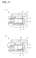
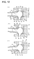
- the spherical guide member 31 rotates in vertical direction in the first and second supporting members 32, 33 as shown in FIGS. 11 , whereby a vertical angular change, which is impossible in the chained link member, is caused to follow a vertical displacement of the cable. If the spherical guide member 31 is rotated to move the first opening 12b upward, the outer circumferential surface of the tube 11 g of the spherical guide member 11 comes into surface contact with the inner circumferential surface of the bearing portion 33c of the second supporting member 33 as shown in FIG. 12(B) .
- the upper surface 31 j of the annular projection 31 h comes into surface contact with the lower surface 32c of the tubular projection 32b of the first supporting member 32 at the side of the spherical guide member 31 toward the first opening 12b and the lower surface 31 k of the annular projection 31 i comes into surface contact with the upper surface 33e of the tubular projection 33d of the second supporting member 33 at the side opposite to the first opening 12b to restrict the rotation of the spherical guide member 11 to the required angle.
- the lower surface 31 k of the annular projection 31 i comes into surface contact with the upper surface 33e of the tubular projection 33d of the second supporting member 33 at the side of the spherical guide member 31 toward the first opening 12b and the upper surface 31 j of the annular projection 31 h comes into surface contact with the lower surface 32c of the tubular projection 32b of the first supporting member 32 at the side opposite to the first opening 12b to restrict the rotation of the spherical guide member 11 to the required angle.
- the spherical guide member 31 rotates in circumferential direction in the first and second supporting members 32, 33 with respect to the opening, whereby the angle of the chained link member changes to follow the angular displacement of the cable in an oblique direction.
- the outer circumferential surface of the tube 11 g of the spherical guide member 31 comes into surface contact with the inner circumferential surface of the bearing portion 33c of the second supporting member 33 and the upper surface 31 j of the annular projection 31h of the spherical guide member 31 or the lower surface 31 k of the annular projection 31i thereof comes into surface contact with the lower surface 32c of the first supporting member 32 or the upper surface 33e of the second supporting member 33 to restrict the rotation of the spherical guide member 31 to the required angle.
- FIG. 13 shows a modification of the second embodiment.
- the annular projections 31 h, 31 i as the second rotational angle restricting portions and the tubular projections 32b, 33d as the second contact portions differ from those of the second embodiment.
- the upper surface 31j of the annular projection 31 h and the lower surface 31 k of the annular projection 31i are horizontal surfaces normal to the longitudinal direction of the tube 11 g, whereas the lower surface 32c of the tubular projection 32b of the first supporting member 32 is inclined upward toward the outer side and the upper surface 33e of the tubular projection 33d of the second supporting member 33 is inclined downward toward the outer side.
- FIG. 14 shows a third embodiment of the present invention.
- the covering member covering the cable drawn out from the spherical guide member 11 of the supporting device 10 differs from that of the first embodiment.
- a corrugate tube 40 in which projected portions and recessed portions are alternately arranged in longitudinal direction, is mounted instead of the chained link member, and an end of the corrugate tube 40 toward the spherical guide member 11 is fitted and fixed in the tubular portion 11 d of the spherical guide member 11.
- the corrugate tube 40 has an oblong cross-sectional shape along a direction normal to the longitudinal direction thereof, wherein the major axis direction of the corrugate tube 40 is a vertical direction and the minor axis direction thereof is a horizontal direction. Further, ribs 41 extending in longitudinal direction are provided at the opposite upper and lower ends of the outer circumferential surface of the corrugate tube 40, thereby making the corrugate tube 40 difficult to vertically bend and easy to transversely bend for the restriction of the bending direction.
- the cross-sectional shape of the corrugate tube along the direction normal to longitudinal direction is not limited to the oblong shape, and may be an elliptical shape or a rectangular shape. If the bending direction can be restricted by the cross-sectional shape of the corrugate tube, it is not necessary to provide the ribs on the outer circumferential surface.
- the cable is not shown in FIG. 13 .
- the bending direction of the corrugate tube 40 is restricted to transverse direction, wherefore the cable can be bent in vertical direction and oblique direction by the rotation of the spherical guide member 11 while being prevented from hanging down.
- the corrugate tube may be connected with the spherical guide member 30 of the second embodiment.
Landscapes
- Engineering & Computer Science (AREA)
- Mechanical Engineering (AREA)
- Architecture (AREA)
- Civil Engineering (AREA)
- Structural Engineering (AREA)
- Electric Cable Arrangement Between Relatively Moving Parts (AREA)
- Details Of Indoor Wiring (AREA)
Abstract
Description
- The present invention relates to a cable supporting device and is particularly designed to support a cable spanning between a slide door of a vehicle and a vehicle body in such a manner as to be able to follow the cable when the cable changes its angle in vertical, transverse and oblique directions as the slide door is opened and closed.
- Electrical parts such as a power window and a door lock are installed a door of an automotive vehicle, and a cable (door harness) for constantly feeding power is connected with these electrical parts. The cable is arranged to extend toward the vehicle body and connected with a power-supply side cable in the vehicle body.
If the door is a slide door, it may move in vertical direction normal to a sliding direction and transverse direction at the time of being closed and opened. Thus, the angle of the cable spanning between the slide door and the vehicle body changes with respect to transverse and vertical directions.
The cable spanning between the slide door and the vehicle body is fixed to and supported on the vehicle body, but it is necessary to provide a mechanism capable of following the angular change of the cable in vertical, transverse and oblique directions in the supporting device. - Japanese Unexamined Patent Publication No.
2004-40862 FIG. 15 as a cable supporting device of this type. In this device, a cable spanning between a vehicle body and a slide door is covered by acable guide 2 formed by connecting a plurality of link members 1, one end of thecable guide 2 is connected with a supporting member 3 fixed to the vehicle body and the cable inserted through thecable guide 2 is passed through the supporting member 3.
The supporting member 3 and thelink member 1 a at the leading end of thecable guide 2 are rotatably connected via a connection pin P1 extending in horizontal direction, so that the link member 1 is swingably connected with the supporting member 3 in vertical direction so as to follow the angular change of the cable in vertical direction. On the other hand, the adjacent link members 1 of thecable guide 2 are connected rotatably in transverse direction by connection pins P2 extending in vertical direction so as to be able to follow the angular change of the cable in transverse direction.
Specifically, by setting the mounting direction of the pins P2 connecting the link members 1 of thecable guide 2 and that of the pin P1 connecting the link member 1 of thecable guide 2 at the leading end of the cable guide and the supporting member 3 orthogonal to each other, a mechanism can follow the angular change of the cable in vertical and transverse directions. - In the cable supporting device of patent document 1, an amount of vertical displacement is restricted to a vertical angular range in which the
link member 1a at the leading end of thecable guide 2 can rotate about the pin P1 and an amount of transverse displacement is restricted to a transverse angular range in which the link members 1 of thecable guide 2 can rotate about the pins P2. Further, the construction of patent document 1 cannot cope with inclining movements in oblique directions. - An amount of vertical angular change of a slide door of an automotive vehicle differs depending on the vehicle type. Further, the slide door is constructed to obliquely move with respect to vertical direction as being slid from a closed state to an open state. This angle of inclination also differs depending on the vehicle type. Further, the mounting position and mounting angle of the cable supporting device on the vehicle also differ.
If the vertical rotational angular range is restricted as in patent document 1, it takes time to consider the mounting position and mounting angle of the cable supporting device for each vehicle type. If the vertical displacement of the cable is large or the angle of inclination thereof is large, the cable itself is twisted in the construction of patent document 1. However, such a displacement or inclination may not be absorbed in some cases. - In patent document 1, the
link member 1 a at the leading end of thecable guide 2 is swingably connected with the cable supporting member 3 in vertical direction, and the link members 1 successively connected with the verticallyswingable link member 1a in forward and backward directions are swingably connected in transverse direction. In other words, the cable passing through thelink member 1a at the leading end is swung in vertical direction, but cannot be swung in transverse direction, and a transverse swinging movement is caused by the link member 1 connected with thelink member 1a and the following link members 1. Therefore, the cable can make no transverse swinging movement at a position proximate to the cable supporting member 3, thereby being twisted in the link members.
Further, since the connecting direction of the verticallyswingable link member 1 a at the leading end with the supporting member 3 by the pin and that of the transversely swingable link members by the pins differ in patent document 1, all the link members cannot have the same shape and thelink member 1a at the leading end needs to be separately provided. This increases the number of parts and, since thelink member 1 a at the leading end is essential, there is a problem of requiring a larger arrangement space. - [Patent Document 1]
Japanese Unexamined Patent Publication No.2004-40862 - The present invention was developed to solve the above problems of document 1 and an object thereof is to provide a cable supporting device capable of coping with amounts of vertical and transverse angular changes of a cable despite their magnitudes, coping with angular changes of the cable in oblique directions and, hence, sufficiently coping with angular changes of the cable even if the mounting position and mounting angle thereof on a vehicle slightly differ.
- In order to solve the above problems, the invention is directed to a cable supporting device for supporting a cable arranged between a vehicle body and a movable member movably connected to the vehicle body, comprising:
- a guide member including a frame body having a three-dimensional surface on the outer surface thereof; and
- a supporting member for rotatably tightly holding the arcuate surface of the guide member, the supporting member being fixed to the vehicle body and/or the movable member,
- wherein:
- the frame body of the guide member includes a first opening and a second opening communicating with a hollow portion thereof and used for the insertion of the cable, a tubular portion projecting from the peripheral edge of the first opening and a rotational angle restricting portion projecting from the outer circumferential surface of the frame body while being spaced apart by a required angle from the tubular portion,
- whereas the supporting member includes a contact portion engageable with the rotational angle restricting portion and at least either one of facing surfaces of the contact portion and the rotational angle restricting portion is an inclined surface, and
- the cable is inserted into the second opening from the first opening of the guide member through the hollowing portion, the changing rotational angle of the cable in transverse direction is restricted by bringing the tubular portion of the guide member into contact with the peripheral edge of the opening of the supporting member, whereas angular changes in vertical and oblique directions are restricted to required angles by bringing the rotational angle restricting portion of the guide member and the contact portion of the supporting member into contact.
- According to the present invention, the cable is supported by being inserted through the hollow portion of the rotatably supported guide member as described above, thereby being able to change its angle over a wide range in any of vertical, transverse and oblique directions.
Thus, as compared to a supporting device as disclosed in patent document 1 in which the angle of a cable can be changed in vertical direction within a specified angular range only between a supporting member and t a link member at the leading end and it can be changed in transverse direction within a specified angular range through the connection of the link members, amounts of angular displacements can be set over wider ranges. Therefore, such amounts of angular displacements are applicable to vehicle types having different directions of displacement and also to vehicle types having different angles of inclination in oblique directions, resulting in good versatility. - Further, since the supporting device of the present invention can cope with any angular changes in vertical, transverse and oblique directions over wide ranges, it is not necessary to consider the mounting position and mounting angle of the supporting device on a vehicle or the like and assemblability at the time of manufacturing can be improved.
Since only the vertical angular change is made and no transverse angular change is made between the supporting member and the link member at the leading end in patent document 1, there is a likelihood that the cable is twisted at this position to exert an excessive load on the cable. However, in the supporting device of the present invention, angular changes can be simultaneously made in vertical, transverse and oblique directions, wherefore there is no likelihood of twisting the cable, thereby protecting the cable. - Since the transverse rotation of the guide member is restricted by the contact of the tubular portion of the guide member with the peripheral edge of the opening of the supporting member and the vertical and oblique rotations thereof are restricted by the contact of the rotational angle restricting portion of the guide member with the contact portion of the supporting member, the damage of the cable due to excessive bending or twisting can be prevented. Particularly, the angles of inclination of the facing surfaces of the rotational angle restricting portion of the guide member and the contact portion of the supporting member are differentiated to bring the rotational angle restricting portion and the contact portion into surface contact when the guide member rotates in vertical or oblique direction. Therefore, the rotational angles of the guide member in vertical and oblique directions can be more accurately and reliably restricted.
The angle of inclination of the facing surface of the contact portion of the supporting member with respect to the facing surface of the projection of the guide member is preferably 3 to 10°. - Specifically, the first opening and the tubular portion of the guide member are provided at one side surface of the frame body, the second opening is formed in the upper end surface substantially orthogonal to the first opening and a tube or a shaft projects from the bottom end surface of the frame body to serve as a first rotational angle restricting portion,
whereas the supporting member includes a first contact portion, which is a bearing portion to be engaged with the first rotation restricting portion, the first contact portion and the first rotational angle restricting portion are fitted while being spaced apart, either one of the inner and outer circumferential surfaces facing each other is an inclined surface, and the angles of the guide member in vertical and oblique directions are restricted by the angle of inclination of the inclined surface. - According to the above construction, if the guide member rotates by the required angle in vertical or oblique direction, the outer circumferential surface of the first rotational angle restricting portion, which is the tube or shaft provided on the guide member, and the inner circumferential surface of the first contact portion, which is the bearing portion provided on the supporting member, come into surface contact, whereby the rotational angles of the guide member in vertical and oblique directions can be more accurately and reliably restricted.
If the angle of the cable changes in transverse direction, the first rotational angle restricting portion of the guide member rotates in the first contact portion of the supporting member, whereby the guide member smoothly follows the rotation of the cable.
The first and second openings are preferably located at orthogonal positions circumferentially spaced apart by 90°, but the angular spacing between the first and second openings is not limited to 90° and is sufficient to be an angle smaller than 180°. Alternatively, the first and second openings may face each other. - Further, an annular projection may project as a second rotational angle restricting portion from a peripheral edge surrounding the second opening of the guide member and/or a peripheral edge at a side vertically opposite to the second opening, and
the supporting member may include a second contact portion, which is a tubular projection fittable to the second rotational angle restricting portion while being spaced apart, at least either one of vertically facing surfaces of the second contact portion and the second rotational angle restricting portion may be an inclined surface, and the angles of the guide member in vertical and oblique directions may be restricted by the angle of inclination of the inclined surface.
Even with the above construction, if the guide member rotates by the required angle in vertical or oblique direction, the vertically facing surfaces of the second rotational angle restricting portion, which is the annular projection provided on the guide member, and the second contact portion, which is the tubular projection of the supporting member, come into surface contact, whereby the rotational angles of the guide member in vertical and oblique directions can be more accurately and reliably restricted. - Preferably, a bearing portion of the first contact portion doubles as the second contact portion and the upper end surface thereof is vertically opposed to the lower end surface of the annular projection of the second rotational angle restricting portion.
By providing the guide member with both first and second rotational angle restricting portions and providing the supporting member with both first and second contact portions, the guide member comes into contact with the supporting member at least at two positions when rotating in vertical or oblique direction, whereby the rotational angles of the guide member in vertical and oblique directions can be more accurately and reliably restricted. - Preferably, the left and right peripheral edges of the opening of the supporting member are formed by mounting contact members separate from the main body of the supporting member.
According to the above construction, the rotational angle of the guide member in transverse direction can be adjusted by replacing only angle restricting members, and the main bodies of other supporting members can be commonly used for other different vehicle types. - Preferably, the guide member is a spherical guide member including a spherical frame body, the first opening and the second opening of the guide member are located at orthogonal positions, and the leading end of a covering member, which is a chained link member or a corrugate tube covering the cable, is so connected to the first opening as to be rotatable within a specified angular range, whereas the cable extending from the leading end of the covering member is passed through the hollow portion of the guide member from the first opening, and pulled out from the second opening to be fixed to the supporting member.
- According to the above construction, in the case of using the chained link member as the covering member for the cable, angular changes in vertical direction, which cannot be made by the chained link member, can be made by the rotation of the guide member. Thus, it is not necessary to connect the link member with the guide member in such a manner as to be vertically swingable, wherefore the link connected with the guide member can have the same shape as the other link members and may be so connected with the guide member as to be transversely swingable. As a result, there is no need to provide the link shaped differently from the other link members as in patent document 1 and the number of parts can be reduced.
The link member at the leading end rotates only in directions different from the other link members in patent document 1, whereas the link member at the leading end rotates in the same directions as the other link members in the case of using the supporting device of the present invention. Thus, an arrangement space can be reduced. Further, since the guide member as the supporting device itself rotates in the supporting device of the present invention, the arrangement space can be further reduced if the guide member is rotated in the same direction as the link members. - The cable is covered by a corrugate tube between the vehicle body and the movable member such as the slide door in some cases other than by the covering member made of the chained link member disclosed in the prior art. In such a case where the cable is covered by the corrugate tube, the corrugate tube can follow the cable not only in transverse direction, but also in vertical direction, but its angular ranges are limited. Therefore, by also supporting the cable covered by the corrugate tube in the vehicle body and/or the slide door using the cable supporting device of the present invention, the supporting device can follow the angular changes of the cable over wider ranges.
In the case of using the corrugate tube instead of the covering member in the form of the chained link member in this way, it is preferable to restrict the bending direction of the corrugate tube to prevent the corrugate tube from coming into contact with an external contact member, for example, by forming ribs extending in lengthwise direction in a specified section to project at a required position of the outer circumferential surface of the corrugate tube. - A supporting surface of the supporting member for rotatably supporting the arcuate surface of the guide member is preferably formed with grooves for discharging foreign matters.
In the case of using the supporting device for a cable arranged between a slide door and a vehicle body, dust, sand and water is likely to enter from the outside at an installation location of this supporting device. Thus, there is a high risk that foreign matters such as dust, sand and water deposit on rotational sliding surfaces of the guide member and the supporting member. In such a case, if the grooves for discharging these foreign matters are provided, a possibility that foreign matters are fixed to the rotational sliding surfaces to hinder the rotation of the guide member can be reliably eliminated. - The cable supporting device of the present invention constructed as described above can be optimally used as the one for a cable arranged between a vehicle body and a slide door, and the angular change of the cable can be followed by the rotation of the guide member as the slide door is opened and closed by fixing the supporting member rotatably tightly holding the guide member to the vehicle body and/or the door.
The cable may be a flat cable in which conductive members are arranged in parallel and laminated with an insulating resin sheet or an insulated round wire. - As described above, according to the present invention, the cable is supported by being inserted through the hollow portion of the guide member rotatably supported by the supporting member. Thus, regardless of in which of vertical, transverse and oblique directions the angle of the cable changes, such an angular change can be followed by the rotation of the guide member, wherefore no excessive load such as a twist is exerted on the cable. Further, only by the supporting device, displacements in vertical and transverse directions can be coped with despite their magnitudes and angular changes of the cable in oblique directions can be coped with.
Further, since the vertical and oblique rotations of the guide member are restricted by bringing the rotational angle restricting portion of the guide member into surface contact with the contact portion of the supporting member, the rotational angles of the guide member in vertical and oblique directions can be more accurately and reliably restricted. -
-
FIG. 1 is a perspective view of a cable supporting device according to a first embodiment of the invention, -
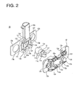
FIG. 2 is an exploded perspective view of the cable supporting device, -
FIG. 3 is a vertical section of the cable supporting device, -
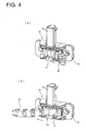
FIGS. 4(A) and 4(B) are diagrams showing a state where a spherical guide member is rotated in transverse direction, -
FIG. 5 is a horizontal section when the spherical guide member is rotated in transverse direction, -
FIGS. 6(A) and 6(B) are diagrams showing a state where the spherical guide member is rotated in vertical direction, -
FIG. 7 is a vertical section when the spherical guide member is rotated in vertical direction, -
FIG. 8 is a diagram showing a modification of the first embodiment, -
FIG. 9 is a perspective view of a cable supporting device according to a second embodiment of the invention, -
FIG. 10 is an exploded perspective view of the cable supporting device, -
FIGS. 11 (A) and 11 (B) are diagrams showing a state where a spherical guide member is rotated in vertical direction, -
FIG. 12(A) is a vertical section showing a state where the spherical guide member is not rotated, andFIGS. 12(B) and 12(C) are vertical sections when the spherical guide member is rotated in vertical direction, -
FIGS. 13(A) to 13(C) are diagrams showing a modification of the second embodiment, -
FIG. 14 is a perspective view of a supporting device according to a third embodiment, and -
FIGS. 15(A) and 15(B) are diagrams showing a prior art device. -
- 10, 30
- cable supporting device
- 11, 31
- spherical guide member
- 11a
- frame body
- 11b
- first opening
- 11c
- second opening
- 11d
- tubular portion
- 11b
- tube (rotational angle restricting portion)
- 12
- first supporting member
- 12c
- opening
- 12d
- bearing portion (contact portion)
- 13
- second supporting member
- 13e
- bearing portion (contact portion)
- 20
- cable
- 21
- link member
- 21 A
- leading-end link member
- 22
- chained link member
- 31 h, 31
- i annular projection (second rotational angle restricting portion)
- 32
- first supporting member
- 32b
- tubular projection (second contact portion)
- 33
- second supporting member
- 33c
- bearing portion (first contact portion)
- 33d
- tubular projection (second contact portion)
- 40
- corrugate tube
-
FIGS. 1 to 7 show a first embodiment of the present invention, and a cable supporting device 10 (hereinafter, referred to as a "supportingdevice 10") is for supporting acable 20 arranged to span between an automotive vehicle body (not shown) and a slide door (not shown) slidably connected to the vehicle body by allowing the cable to be inserted therethrough. - As shown in
FIGS. 1 and2 , the supportingdevice 10 includes aspherical guide member 11 made of resin and a pair of first and second supportingmembers spherical guide member 11 therebetween.
Thespherical guide member 11 has aspherical frame body 11a, afirst opening 11 b communicating with a spherical hollow portion S1 of theframe body 11 a is formed in one side surface of theframe body 11a, and asecond opening 11c communicating with the hollow portion S1 is formed in the upper side spaced apart by 90° from thefirst opening 11b. Acylindrical tubular portion 11d projects from the peripheral edge of thefirst opening 11 b, and a pair of connectingpieces 11e project from the opposite upper and lower edges at the leading end of thetubular portion 11 d, wherein pin-shapedprojections 11f are provided on these connectingpieces 11e. Further, acylindrical tube 11 g, which serves as a (first) rotational angle restricting portion, projects downward from the bottom end of theframe body 11a orthogonal to thefirst opening 11 b. Thetube 11 g has a uniform outer diameter from the upper end to the bottom end.
Although the rotational angle restricting portion is a tube, it may be a solid shaft. - On the other hand, the
cable 20 is covered by a chainedlink member 22 in which a multitude of link members are successively rotatably connected. The pair of connectingpieces 11 e are placed on and rotatably connected with a leading-end link member 21 A of this chainedlink member 22. Thus, the chainedlink member 22 is so connected with thespherical guide member 11 as to be able to change its angle in transverse direction (swingable in transverse direction). - The first supporting
member 12 for tightly holding thespherical guide member 11 at one side includes supportingframes 12a in the form of upper and lower frames for rotatably tightly supporting thespherical guide member 11 and vehicle-body fixing portions 12b in the form of plates projecting sideways from the opposite left and right sides of the supportingframes 12a. A substantiallyrectangular opening 12c surrounded by the upper and lower supportingframes 12a and the left and right vehicle-body fixing portions 12b is formed in the center of the first supportingmember 12. The transverse center of the lower supportingframe 12a is arcuately recessed to form abearing portion 12d, which serves as a (first) contact portion. The inner circumferential surface of the bearingportion 12d is widened toward the bottom end, and a plurality ofgrooves 12g for discharging foreign matters are formed in the inner circumferential surface of the bearingportion 12d to extend from the upper end to the bottom end while being circumferential spaced apart. Further,bolt holes 12f are formed in the vehicle-body fixing portions 12b of the first supportingmember 12. - The second supporting
member 13 for tightly holding thespherical guide member 11 at the other side includes a supportingportion 13a in the form of a thick plate for rotatably tightly supporting thespherical guide member 11, vehicle-body fixing portions 13b in the form of thin plates projecting sideways from the opposite left and right sides of the supportingportion 13a, and atubular portion 13c projecting upward from the upper side of the supportingportion 13a and having a hollow portion S2. A recessedportion 13d in conformity with the outer surface of theframe body 11a of thespherical guide member 11 is formed in the center of the supportingportion 13a, and a bearingportion 13e, which has the same shape as the bearingportion 12d of the first supportingmember 12 and serves as a (first) contact portion, is provided below the recessedportion 13d. A plurality ofgrooves 13h for discharging foreign matters are formed in the inner circumferential surface of the bearingportion 13e to extend from the upper end to the bottom end while being circumferential spaced apart. Left andright contact portions 13i for restricting the rotational angle of thespherical guide member 11 in transverse direction project at the opposite left and right sides of the recessedportion 13d, and fourlocking pieces 13f to be inserted into the lockingholes 12e of the first supportingmember 12 for locking engagement are formed around the recessedportion 13d. Further, the vehicle-body fixing portions 13b are formed withbolt holes 13g. - With the
spherical guide member 11 tightly held by the first and second supportingmembers pieces 13f of the second supportingmember 13 are inserted into the lockingholes 12e of the first supportingmember 12 for locking engagement to connect the first and second supportingmembers FIG. 1 , whereby thespherical guide member 11 is rotatably tightly held by the first and second supportingmembers pieces 11 e of thefirst opening 11 b of thespherical guide member 11 are caused to project from theopening 12c of the first supportingmember 12, whereas thesecond opening 11c communicates with the hollow portion S2 of thetubular portion 13c of the second supportingmember 13. Further, the bearingportion 12d of the first supportingmember 12 and the bearingportion 13e of the second supportingmember 13 are opposed to each other, thereby forming one bearing portion (contact portion) having a truncated conical shape and an inner circumferential surface widened toward the bottom end. In this embodiment, the inner circumferential surfaces of the bearingportions tube 11 g of thespherical guide member 11. - The
cable 20 as a bundle of a plurality of wires arranged between the slide door and the vehicle body is inserted through the supportingdevice 10 having thespherical guide member 11 and the first and second supportingmembers cable 20 inserted into the hollow portion S1 of thespherical guide member 11 from thefirst opening 11 b is bent at 90° and inserted into the hollow space S2 of thetubular portion 13c through thesecond opening 11c, and thecable 20 pulled out from the upper end of thetubular portion 13c is fixed to the upper end of thetubular portion 13c by winding a tape T.
Further, upon being mounted on the vehicle, the supportingdevice 10 is fixed to a vehicle body panel by inserting unillustrated bolts (fastening members) through the communicatingbolt holes - The
cable 20 pulled out from thetubular portion 13c of the second supportingmember 13 of the supportingdevice 10 is arranged in the vehicle body to be connected with a floor harness (not shown) by means of a connector, whereas thecable 20 inserted into thefirst opening 11 b of thespherical guide member 11 is arranged to span between the vehicle body and the slide door and connected with a door harness (not shown) by means of a connector. In this way, the floor harness and the door harness are electrically connected via thecable 20. - The
cable 20 inserted into thefirst opening 11 b is covered by the chainedlink member 22 in which a plurality oflink members 21 are connected. Thelink members 21 have a rectangular tubular shape. As shown inFIG. 3 , a round throughhole 21 a is formed at the front or rear side of each of the upper and lower walls opposed to each other, and a pin-shapedprojection 21 b is provided on the opposite side thereof. A plurality of link members are so connected with each other as to be rotatable in transverse direction by fitting the pin-shapedprojections 21 b of onelink member 21 into the throughholes 21 a of theadjacent link member 21. The through holes 21 a of the leading-end link member 21A of the chainedlink member 22 covering thecable 20 are engaged with the pin-shapedprojections 11f of the connectingpieces 11e of thespherical guide member 11 to rotatably connect the leading-end link member 21 A. By connecting in this way, the chainedlink member 22 can be bent in transverse direction.
It should be noted that the link members and the leading-end link member and thespherical guide member 11 may be rotatably connected using separate pins. - As described above, according to the present invention, the
cable 20 spanning between the vehicle body and the slide door is covered by the chainedlink member 22, inserted into thefirst opening 11 b of thespherical guide member 11 connected with the leading-end link member 21 A of the chainedlink member 22 at the vehicle body side, brought to thesecond opening 11c after passing the hollow portion S1 and pulled out through the hollow portion S2 of thetubular portion 13c from thesecond opening 11c. - Structurally, the chained
link member 22 is bendable only in transverse direction, but thespherical guide member 11 is rotatably supported by the first and second supportingmembers cable 20 inserted through thespherical guide member 11 changes in vertical, transverse or oblique direction, thespherical guide member 11 rotates to follow this angular change, wherefore the angle of thecable 20 smoothly changes. - For example, if the slide door is moved in transverse direction and the
cable 20 is displaced also in transverse direction, thespherical guide member 11 rotates in transverse direction in the first and second supportingmembers FIGS. 4 , whereby the angle changes in transverse direction over a wider range as compared to the transverse angular displacement only by the chainedlink member 22 to follow the angular change of thecable 20 in transverse direction. At this time, thetubular portion 11 d of thespherical guide member 11 comes into contact with the left andright contact portions 13i of thesecond guide member 13 as shown inFIG. 5 , whereby the transverse rotation of thespherical guide member 11 is restricted to a required angle. - Further, if the slide door is moved in vertical direction and the
cable 20 is displaced also in vertical direction, thespherical guide member 11 rotates in vertical direction in the first and second supportingmembers FIGS. 6 , whereby a vertical angular change, which is impossible in the chainedlink member 22, is caused to follow a vertical displacement of the cable. If thespherical guide member 11 is rotated to move thefirst opening 12b upward, thetube 11 g of thespherical guide member 11 is inclined toward the first supportingmember 12 and the outer circumferential surface of thetube 11g comes into surface contact with the inner circumferential surface of the bearingportion 12d of the first supportingmember 12 as shown inFIG. 7 , whereby the rotation of thespherical guide member 11 is restricted to a required angle. Conversely, if thespherical guide member 11 is rotated to move thefirst opening 12b downward, thetube 11 g of thespherical guide member 11 is inclined toward the second supportingmember 13 and the outer circumferential surface of thetube 11 g comes into surface contact with the inner circumferential surface of the bearingportion 13e of the second supportingmember 13, whereby the rotation of thespherical guide member 11 is restricted to a required angle. Since the inner circumferential surfaces of the bearingportions tube 11 g of thespherical guide member 11 in this embodiment, thespherical guide member 11 rotates only by 5° upward and downward. - Furthermore, if the slide door is inclined during its sliding movement and the angle of inclination of the
cable 20 is also changed, thespherical guide member 11 rotates in circumferential direction in the first and second supportingmembers opening 12c, whereby the angle of the chainedlink member 22 changes to follow the angular displacement of thecable 20 in an oblique direction. At this time as well, the outer circumferential surface of thetube 11 g of thespherical guide member 11 comes into surface contact with the inner circumferential surfaces of the bearingportions members spherical guide member 11 to a required angle - As described above, in the supporting
device 10 of the present invention, the angular changes of the cable in vertical, transverse and oblique directions can be followed by the rotation of thespherical guide member 11 and the amount of displacement of the cable is large. Therefore, this supportingdevice 10 can be used for other types of vehicles.
Since the rotations of thespherical guide member 11 in vertical and oblique directions are restricted by the surface contact of thetube 11 g of thespherical guide member 11 with the bearingportions members spherical guide member 11 in vertical and oblique directions can be more accurately and reliably restricted.
Further, since the connecting mode of the link members of the chained link member and that of the leading-end link member and the first supporting member of the supporting device are the same, the leading-end link member can have the same shape as the other link members, wherefore the number of parts can be reduced and the leading-end link member and the supporting member can be easily connected. - Although the supporting
device 10 is fixed to the vehicle body in this embodiment, it may be provided on the slide door depending on the vehicle type or may be provided on both the vehicle body and the slide door. If the supportingdevice 10 is provided on both the vehicle body and the slide door, the movable range of the cable can be widened. -
FIG. 8 shows a modification of the first embodiment.
In this modification, thetube 11 g of thespherical guide member 11 has a truncated conical shape narrowed toward the bottom end, whereas the inner circumferential surfaces of the bearingportions members
Even with the above construction, if thespherical guide member 11 is rotated in vertical or oblique direction, thetube 11 g of thespherical guide member 11 comes into surface contact with the bearingportions members spherical guide member 11 in vertical and oblique directions can be more precisely and reliably restricted.
Since the other construction, functions and effects are the same as in the first embodiment, no description is given thereon by identifying the other construction by the same reference numerals. -
FIGS. 9 to 12 show a second embodiment of the present invention.
Acable supporting device 30 of this embodiment is provided with aspherical guide member 31 having substantially the same shape as in the first embodiment, a supporting membermain body 34 comprised of first and second supportingmembers spherical guide member 31 andcontact members 35 for restricting the transverse rotational angle of thespherical guide member 31. - Although the
spherical guide member 31 has substantially the same shape as in the first embodiment,annular projections second opening 11c and atube 11 g, project at positions of the outer surface of thespherical frame body 11 a at required distances from both upper and lower ends. Theseannular projections frame body 11 and, as shown inFIG. 12 , anupper surface 31 j of the upperannular projection 31 h is inclined downward toward the outer projecting end, whereas alower surface 31 k of the lowerannular projection 31i is inclined upward toward the outer projecting end. - The first supporting
member 32 for tightly holding thespherical guide member 31 from above is in the form of a flat plate, a throughhole 32a used for the insertion of a cable is formed in the center of the first supportingmember 32, and atubular projection 32b (second contact portion) projects downward from the lower peripheral edge of the throughhole 32a. Alower surface 32c of thetubular projection 32b is a horizontal surface, which serves as a contact surface with theannular projection 31 h provided on thespherical guide member 31. Further, anarcuate surface 32e in conformity with the outer circumferential surface of thespherical guide member 31 is formed in thelower surface 32c of thetubular projection 32b along the peripheral edge of the throughhole 32a. - The second supporting
member 33 for tightly holding thespherical guide member 31 from below is comprised of abottom wall portion 33a in the form of a flat plate and an L-shapedside wall portion 33b projecting upward from thebottom wall portion 33a. Thebottom wall portion 33a is formed with a bearingportion 33c, which is a through hole having a truncated conical shape similar to the first embodiment and serves as a first contact portion, at a position facing the throughhole 32a of the first supportingmember 32. The bearingportion 33c is also formed with a plurality of grooves (not shown) for discharging foreign matters, which extend from the upper end to the bottom end while being circumferential spaced apart. Atubular projection 33d (second contact portion) projects upward also from the upper peripheral edge of the bearingportion 33c, and a horizontalupper surface 33e of thetubular projection 33d serves as a contact surface with theannular projection 31 i provided on thespherical guide member 31. Further, anarcuate surface 33g in conformity with the outer circumferential surface of thespherical guide member 31 is formed in theupper surface 33e of thetubular projection 33d along the peripheral edge of the bearingportion 33c.
The second supportingmember 33 is provided with a vehicle-body fixing portion 33f, and the supportingdevice 30 is fixed to a vehicle body by fastening bolts inserted through bolt holes (not shown) formed in the vehicle-body fixing portion 33f. - The
contact members 35 are fixed at the opposite left and right sides of a space defined between the first and second supportingmembers portion 35a to be brought into contact with thetubular portion 11 d of thespherical guide member 31 rotating in transverse direction is formed in the inner surface of eachcontact member 35. With thespherical guide member 31, the first and second supportingmembers contact members 35 assembled with each other, thespherical guide member 31 is rotatably tightly held from above and below by thearcuate surfaces tubular projections tubular projections annular projections
Although not shown, the first and second supportingmembers contact members 35 are interlocked with each other. - A chained link member similar to that of the first embodiment is rotatably connected with the connecting
pieces 11e of thespherical guide member 31, and a cable is inserted through the chained link member to span between the vehicle body and a slide door. - If the slide door is displaced in transverse direction and the cable is also displaced in transverse direction, the
spherical guide member 11 rotates in transverse direction in the first and second supportingmembers tubular portion 11 d of thespherical guide member 31 comes into contact with thecontact member 35, whereby the transverse rotation of thespherical guide member 11 is restricted to the required angle. - If the slide door is displaced in vertical direction and the cable is also displaced in vertical direction, the
spherical guide member 31 rotates in vertical direction in the first and second supportingmembers FIGS. 11 , whereby a vertical angular change, which is impossible in the chained link member, is caused to follow a vertical displacement of the cable. If thespherical guide member 31 is rotated to move thefirst opening 12b upward, the outer circumferential surface of thetube 11 g of thespherical guide member 11 comes into surface contact with the inner circumferential surface of the bearingportion 33c of the second supportingmember 33 as shown inFIG. 12(B) . Further, theupper surface 31 j of theannular projection 31 h comes into surface contact with thelower surface 32c of thetubular projection 32b of the first supportingmember 32 at the side of thespherical guide member 31 toward thefirst opening 12b and thelower surface 31 k of theannular projection 31 i comes into surface contact with theupper surface 33e of thetubular projection 33d of the second supportingmember 33 at the side opposite to thefirst opening 12b to restrict the rotation of thespherical guide member 11 to the required angle. Conversely, if thespherical guide member 31 is rotated to move thefirst opening 12b downward, the outer circumferential surface of thetube 11 g of thespherical guide member 31 comes into surface contact with the inner circumferential surface of the bearingportion 33c of the second supportingmember 33 as shown inFIG. 12(C) . Further, thelower surface 31 k of theannular projection 31 i comes into surface contact with theupper surface 33e of thetubular projection 33d of the second supportingmember 33 at the side of thespherical guide member 31 toward thefirst opening 12b and theupper surface 31 j of theannular projection 31 h comes into surface contact with thelower surface 32c of thetubular projection 32b of the first supportingmember 32 at the side opposite to thefirst opening 12b to restrict the rotation of thespherical guide member 11 to the required angle. - Furthermore, if the slide door is inclined during its sliding movement and the angle of inclination of the cable is also changed, the
spherical guide member 31 rotates in circumferential direction in the first and second supportingmembers tube 11 g of thespherical guide member 31 comes into surface contact with the inner circumferential surface of the bearingportion 33c of the second supportingmember 33 and theupper surface 31 j of theannular projection 31h of thespherical guide member 31 or thelower surface 31 k of theannular projection 31i thereof comes into surface contact with thelower surface 32c of the first supportingmember 32 or theupper surface 33e of the second supportingmember 33 to restrict the rotation of thespherical guide member 31 to the required angle. -
FIG. 13 shows a modification of the second embodiment.
In this modification, theannular projections tubular projections upper surface 31j of theannular projection 31 h and thelower surface 31 k of theannular projection 31i are horizontal surfaces normal to the longitudinal direction of thetube 11 g, whereas thelower surface 32c of thetubular projection 32b of the first supportingmember 32 is inclined upward toward the outer side and theupper surface 33e of thetubular projection 33d of the second supportingmember 33 is inclined downward toward the outer side. - Even with the above construction, if the
spherical guide member 11 is rotated in vertical or oblique direction, theupper surface 31 j of theannular projection 31 h of thespherical guide member 31 or thelower surface 31 k of theannular projection 31 i thereof comes into surface contact with the inclinedlower surface 32c of thetubular projection 32b or the inclinedupper surface 33e of thetubular projection 33d to restrict the rotation of thespherical guide member 11 to a required angle. -
FIG. 14 shows a third embodiment of the present invention.
In this embodiment, the covering member covering the cable drawn out from thespherical guide member 11 of the supportingdevice 10 differs from that of the first embodiment. Specifically, in this embodiment, acorrugate tube 40, in which projected portions and recessed portions are alternately arranged in longitudinal direction, is mounted instead of the chained link member, and an end of thecorrugate tube 40 toward thespherical guide member 11 is fitted and fixed in thetubular portion 11 d of thespherical guide member 11. Thecorrugate tube 40 has an oblong cross-sectional shape along a direction normal to the longitudinal direction thereof,
wherein the major axis direction of thecorrugate tube 40 is a vertical direction and the minor axis direction thereof is a horizontal direction. Further,ribs 41 extending in longitudinal direction are provided at the opposite upper and lower ends of the outer circumferential surface of thecorrugate tube 40, thereby making thecorrugate tube 40 difficult to vertically bend and easy to transversely bend for the restriction of the bending direction.
The cross-sectional shape of the corrugate tube along the direction normal to longitudinal direction is not limited to the oblong shape, and may be an elliptical shape or a rectangular shape. If the bending direction can be restricted by the cross-sectional shape of the corrugate tube, it is not necessary to provide the ribs on the outer circumferential surface.
The cable is not shown inFIG. 13 . - According to the above construction, the bending direction of the
corrugate tube 40 is restricted to transverse direction, wherefore the cable can be bent in vertical direction and oblique direction by the rotation of thespherical guide member 11 while being prevented from hanging down.
It should be noted that the corrugate tube may be connected with thespherical guide member 30 of the second embodiment.
Claims (7)
- A cable supporting device for supporting a cable arranged between a vehicle body and a movable member movably connected to the vehicle body, comprising:a guide member including a frame body having a three-dimensional surface on the outer surface thereof; anda supporting member for rotatably tightly holding the arcuate surface of the guide member, the supporting member being fixed to the vehicle body and/or the movable member,wherein:the frame body of the guide member includes a first opening and a second opening communicating with a hollow portion thereof and used for the insertion of the cable, a tubular portion projecting from the peripheral edge of the first opening and a rotational angle restricting portion projecting from the outer circumferential surface of the frame body while being spaced apart by a required angle from the tubular portion,whereas the supporting member includes a contact portion engageable with the rotational angle restricting portion and at least either one of facing surfaces of the contact portion and the rotational angle restricting portion is an inclined surface, andthe cable is inserted into the second opening from the first opening of the guide member through the hollowing portion, the changing rotational angle of the cable in transverse direction is restricted by bringing the tubular portion of the guide member into contact with the peripheral edge of the opening of the supporting member, whereas angular changes in vertical and oblique directions are restricted to required angles by bringing the rotational angle restricting portion of the guide member and the contact portion of the supporting member into contact.
- A cable supporting device according to claim 1, wherein:the first opening and the tubular portion of the guide member are provided at one side surface of the frame body, the second opening is formed in the upper end surface substantially orthogonal to the first opening and a tube or a shaft projects from the bottom end surface of the frame body to serve as a first rotational angle restricting portion,whereas the supporting member includes a first contact portion, which is a bearing portion to be engaged with the first rotation restricting portion, the first contact portion and the first rotational angle restricting portion are fitted while being spaced apart, either one of the inner and outer circumferential surfaces facing each other is an inclined surface, and the angles of the guide member in vertical and oblique directions are restricted by the angle of inclination of the inclined surface.
- A cable supporting device according to claim 1 or 2, wherein:an annular projection projects as a second rotational angle restricting portion from a peripheral edge surrounding the second opening of the guide member and/or a peripheral edge at a side vertically opposite to the second opening, andthe supporting member includes a second contact portion, which is a tubular projection fittable to the second rotational angle restricting portion while being spaced apart, at least either one of vertically facing surfaces of the second contact portion and the second rotational angle restricting portion is an inclined surface, and the angles of the guide member in vertical and oblique directions are restricted by the angle of inclination of the inclined surface.
- A cable supporting device according to claim 3, wherein a bearing portion of the first contact portion doubles as the second contact portion and the upper end surface thereof is vertically opposed to the lower end surface of the annular projection of the second rotational angle restricting portion.
- A cable supporting device according to any one of claims 1 to 4,
wherein the left and right peripheral edges of the opening of the supporting member surrounding the tubular portion of the guide member are formed by mounting contact members separate from a supporting member main body. - A cable supporting device according to any one of claims 1 to 5,
wherein:the guide member is a spherical guide member including a spherical frame body,the first opening and the second opening of the guide member are located at orthogonal positions, andthe leading end of a covering member, which is a chained link member or a corrugate tube covering the cable, is so connected to the first opening as to be rotatable within a specified angular range, whereas the cable extending from the leading end of the covering member is passed through the hollow portion of the guide member from the first opening, and pulled out from the second opening to be fixed to the supporting member. - A cable supporting device according to any one of claims 1 to 6,
wherein:the cable is arranged between the vehicle body and a slide door,the supporting member for rotatably tightly holding the guide member is fixed to the vehicle body and/or the slide door, andthe guide member rotates to follow the angular change of the cable as the slide door is opened and closed.
Applications Claiming Priority (2)
| Application Number | Priority Date | Filing Date | Title |
|---|---|---|---|
| JP2005315809A JP4862358B2 (en) | 2005-10-31 | 2005-10-31 | Cable support device |
| PCT/JP2006/313739 WO2007052386A1 (en) | 2005-10-31 | 2006-07-11 | Device for supporting cable |
Publications (3)
| Publication Number | Publication Date |
|---|---|
| EP1944198A1 true EP1944198A1 (en) | 2008-07-16 |
| EP1944198A4 EP1944198A4 (en) | 2010-06-16 |
| EP1944198B1 EP1944198B1 (en) | 2011-12-21 |
Family
ID=38005547
Family Applications (1)
| Application Number | Title | Priority Date | Filing Date |
|---|---|---|---|
| EP06780960A Expired - Lifetime EP1944198B1 (en) | 2005-10-31 | 2006-07-11 | Device for supporting cable |
Country Status (5)
| Country | Link |
|---|---|
| US (1) | US7804027B2 (en) |
| EP (1) | EP1944198B1 (en) |
| JP (1) | JP4862358B2 (en) |
| CN (1) | CN101300155B (en) |
| WO (1) | WO2007052386A1 (en) |
Cited By (3)
| Publication number | Priority date | Publication date | Assignee | Title |
|---|---|---|---|---|
| GB2458754A (en) * | 2008-03-31 | 2009-10-07 | Mitsubishi Motors Corp | Vehicle power line supporting structure |
| WO2021160884A1 (en) * | 2020-02-16 | 2021-08-19 | Volkswagen Ag | Cable guide and motor vehicle |
| DE112014004691B4 (en) | 2013-10-11 | 2021-08-26 | Yazaki Corporation | Power supply device |
Families Citing this family (32)
| Publication number | Priority date | Publication date | Assignee | Title |
|---|---|---|---|---|
| JP4997944B2 (en) * | 2006-03-07 | 2012-08-15 | 日産自動車株式会社 | Power supply unit |
| JP5012063B2 (en) * | 2007-02-05 | 2012-08-29 | 住友電装株式会社 | Wiring harness wiring structure for automobile |
| JP4978342B2 (en) * | 2007-07-02 | 2012-07-18 | 日産自動車株式会社 | Power supply unit |
| JP4998161B2 (en) * | 2007-09-11 | 2012-08-15 | 住友電装株式会社 | Joint holder |
| WO2009113636A1 (en) * | 2008-03-14 | 2009-09-17 | 矢崎総業株式会社 | Protector structure of power supply device |
| JP5200964B2 (en) * | 2009-02-03 | 2013-06-05 | 住友電装株式会社 | Support device for wire harness for sliding door |
| JP4858590B2 (en) * | 2009-09-30 | 2012-01-18 | ブラザー工業株式会社 | Image processing device |
| JP5605163B2 (en) * | 2010-10-25 | 2014-10-15 | 住友電装株式会社 | Sliding door feeding structure |
| JP5356357B2 (en) * | 2010-11-02 | 2013-12-04 | 古河電気工業株式会社 | Power supply device for sliding door |
| JP5929029B2 (en) * | 2011-08-04 | 2016-06-01 | 住友電装株式会社 | Wire harness wiring device |
| JP5826615B2 (en) * | 2011-11-24 | 2015-12-02 | 矢崎総業株式会社 | Shield connection unit |
| CN103511751B (en) * | 2012-06-20 | 2015-09-02 | 南车青岛四方机车车辆股份有限公司 | Flexible pipe line angle fixing device |
| JP6029138B2 (en) * | 2013-01-22 | 2016-11-24 | 矢崎総業株式会社 | Power supply device |
| US9762043B2 (en) * | 2013-09-03 | 2017-09-12 | Marmon Utility Llc | Impact-absorbing wire and cable fixture, system, and related methods |
| JP6146909B2 (en) * | 2013-10-11 | 2017-06-14 | 矢崎総業株式会社 | Power feeding device and method for assembling power feeding device |
| US9956928B2 (en) * | 2015-06-30 | 2018-05-01 | Fca Us Llc | Track assembly for sliding vehicle door |
| JP6202057B2 (en) * | 2015-07-29 | 2017-09-27 | 住友電装株式会社 | Cable guide mounting structure |
| JP6558312B2 (en) * | 2016-06-24 | 2019-08-14 | 住友電装株式会社 | Guide end of cable guide, cable guide and wire harness |
| JP6594541B2 (en) * | 2016-06-24 | 2019-10-30 | 住友電装株式会社 | Cable guide device and wire harness |
| JP2018077396A (en) * | 2016-11-10 | 2018-05-17 | 株式会社リコー | Image forming apparatus |
| JP6873828B2 (en) * | 2017-05-31 | 2021-05-19 | 株式会社ミツバ | Vehicle switchgear |
| JP6841724B2 (en) * | 2017-06-07 | 2021-03-10 | 住友電装株式会社 | Electric wire guide device |
| JP2019100513A (en) * | 2017-12-07 | 2019-06-24 | 矢崎総業株式会社 | Corrugate tube holder |
| JP6804490B2 (en) * | 2018-06-27 | 2020-12-23 | 矢崎総業株式会社 | Wire harness, power supply device equipped with the wire harness |
| KR102272965B1 (en) * | 2019-01-16 | 2021-07-05 | 윤종철 | Cable supporting module and cable unit having the same |
| JP7278683B2 (en) * | 2019-01-24 | 2023-05-22 | 矢崎総業株式会社 | power supply |
| JP6807418B2 (en) * | 2019-02-08 | 2021-01-06 | 株式会社城南製作所 | Wind regulator |
| CN110629673B (en) * | 2019-09-25 | 2024-11-22 | 中交二公局第五工程有限公司 | Cable strand free rotation anchor head connection device |
| CN110994489B (en) * | 2019-11-25 | 2021-06-11 | 马鞍山南凌新能源汽车电器有限公司 | Soft backplate of multilayer for low pressure car pencil |
| JP7526146B2 (en) * | 2021-08-19 | 2024-07-31 | 株式会社ハイレックスコーポレーション | Drives and boots |
| EP4147916B1 (en) * | 2021-09-09 | 2025-05-07 | Newfrey LLC | Pivoting arrangement and cable-guide arrangement |
| CN114336442B (en) * | 2021-11-25 | 2023-06-02 | 北京特种机械研究所 | Differential wheel set self-adaptive wiring mechanism |
Family Cites Families (15)
| Publication number | Priority date | Publication date | Assignee | Title |
|---|---|---|---|---|
| GB1560099A (en) * | 1976-12-08 | 1980-01-30 | Bowthorpe Hellermann Ltd | Clip for fixing and electric cable to a support structure |
| DE29622261U1 (en) * | 1996-12-21 | 1997-03-20 | EMU Unterwasserpumpen GmbH, 95030 Hof | Protection device for the power cable of a submersible pump |
| US6285565B1 (en) * | 1999-06-04 | 2001-09-04 | Telefonaktiebolaget Lm Ericsson (Publ) | Cable support apparatus |
| JP3743279B2 (en) * | 2000-10-30 | 2006-02-08 | 日産自動車株式会社 | Slide harness door harness wiring structure |
| US7073754B2 (en) * | 2002-02-28 | 2006-07-11 | Ductmate Industries, Inc. | Cable support systems |
| JP3836758B2 (en) | 2002-07-01 | 2006-10-25 | 本田技研工業株式会社 | Cable support structure |
| JP4261947B2 (en) | 2003-03-14 | 2009-05-13 | 矢崎総業株式会社 | Harness fixture for sliding door feeding and feeding structure using it |
| US6953896B2 (en) * | 2003-04-29 | 2005-10-11 | Carlyle, Inc. | Cable support device for rack-mounted equipment and the like |
| US7485801B1 (en) * | 2005-03-11 | 2009-02-03 | Marathon Petroleum Co. | Heat trace or control cable support with insulating jackets |
| US7473846B2 (en) * | 2006-03-29 | 2009-01-06 | Hewlett-Packard Development Company, L.P. | Reversible cable support arm |
| US7304240B1 (en) * | 2006-06-20 | 2007-12-04 | Arlington Industries, Inc. | Cable support assembly for minimizing bend radius of cables |
| US7470859B1 (en) * | 2006-06-20 | 2008-12-30 | Arlington Industries, Inc. | Cable support assembly for minimizing the bend radius of cables |
| US7915542B2 (en) * | 2007-07-09 | 2011-03-29 | Forbis Robert C | Electrical cable support bracket |
| US7770344B2 (en) * | 2007-10-03 | 2010-08-10 | Cooper Technologies Company | Under-floor cable support system |
| US20090283318A1 (en) * | 2008-05-13 | 2009-11-19 | Honeywell International Inc. | Integrated EMI Shield Termination and Cable Support Apparatus |
-
2005
- 2005-10-31 JP JP2005315809A patent/JP4862358B2/en not_active Expired - Fee Related
-
2006
- 2006-07-11 WO PCT/JP2006/313739 patent/WO2007052386A1/en not_active Ceased
- 2006-07-11 EP EP06780960A patent/EP1944198B1/en not_active Expired - Lifetime
- 2006-07-11 US US12/083,712 patent/US7804027B2/en active Active
- 2006-07-11 CN CN2006800408461A patent/CN101300155B/en not_active Expired - Fee Related
Non-Patent Citations (2)
| Title |
|---|
| No further relevant documents disclosed * |
| See also references of WO2007052386A1 * |
Cited By (5)
| Publication number | Priority date | Publication date | Assignee | Title |
|---|---|---|---|---|
| GB2458754A (en) * | 2008-03-31 | 2009-10-07 | Mitsubishi Motors Corp | Vehicle power line supporting structure |
| GB2458754B (en) * | 2008-03-31 | 2010-06-09 | Mitsubishi Motors Corp | Vehicle power line supporting structure |
| DE112014004691B4 (en) | 2013-10-11 | 2021-08-26 | Yazaki Corporation | Power supply device |
| WO2021160884A1 (en) * | 2020-02-16 | 2021-08-19 | Volkswagen Ag | Cable guide and motor vehicle |
| US12162414B2 (en) | 2020-02-16 | 2024-12-10 | Newfrey Llc | Cable guide and motor vehicle |
Also Published As
| Publication number | Publication date |
|---|---|
| JP2007118849A (en) | 2007-05-17 |
| US20090140107A1 (en) | 2009-06-04 |
| JP4862358B2 (en) | 2012-01-25 |
| CN101300155A (en) | 2008-11-05 |
| US7804027B2 (en) | 2010-09-28 |
| EP1944198A4 (en) | 2010-06-16 |
| WO2007052386A1 (en) | 2007-05-10 |
| EP1944198B1 (en) | 2011-12-21 |
| CN101300155B (en) | 2010-12-29 |
Similar Documents
| Publication | Publication Date | Title |
|---|---|---|
| EP1944198B1 (en) | Device for supporting cable | |
| EP1936767B1 (en) | Device for supporting cable | |
| EP3766742B1 (en) | Slide door harness | |
| US9150168B2 (en) | Sliding door wire harness routing structure | |
| US20070158092A1 (en) | Harness wire cover and harness wiring structure having the same | |
| US20200194948A1 (en) | Support assembly with a support member and a track assembly | |
| EP2119600A1 (en) | Wire harness cabling structure for automobile | |
| US20070127193A1 (en) | Wiring fixing member | |
| CN116653807B (en) | Wire harness routing structure, connecting rod type sliding door and wire harness | |
| US6428341B2 (en) | Inspecting jig for wire harness | |
| JP7430740B2 (en) | Wire harness wiring structure, link type sliding door, and wire harness | |
| JP4893332B2 (en) | Wire harness wiring support device | |
| JP2007159372A (en) | Cable guide | |
| JP2007174735A (en) | Cable guiding apparatus | |
| JP2007159369A (en) | Cable guide | |
| JP2007181333A (en) | Power feeding device for slide structure | |
| JP7723026B2 (en) | Protectors and Wire Harnesses | |
| US20250333009A1 (en) | Protector and wire harness | |
| JP7732850B2 (en) | Clamps and clamp-equipped wire harnesses | |
| JP2025032516A (en) | Protector unit and wire harness | |
| JP2007143212A (en) | Protective structure of wire harness | |
| KR20260053164A (en) | Cable-veyor assembly of wiring module between body and sliding door for vehicle | |
| HK1182999B (en) | Sliding door wire harness routing structure | |
| JP2008094191A (en) | Power supply device |
Legal Events
| Date | Code | Title | Description |
|---|---|---|---|
| PUAI | Public reference made under article 153(3) epc to a published international application that has entered the european phase |
Free format text: ORIGINAL CODE: 0009012 |
|
| 17P | Request for examination filed |
Effective date: 20080417 |
|
| AK | Designated contracting states |
Kind code of ref document: A1 Designated state(s): DE FR |
|
| DAX | Request for extension of the european patent (deleted) | ||
| RBV | Designated contracting states (corrected) |
Designated state(s): DE FR |
|
| A4 | Supplementary search report drawn up and despatched |
Effective date: 20100520 |
|
| GRAP | Despatch of communication of intention to grant a patent |
Free format text: ORIGINAL CODE: EPIDOSNIGR1 |
|
| RIC1 | Information provided on ipc code assigned before grant |
Ipc: H02G 3/04 20060101ALI20110110BHEP Ipc: B60R 16/02 20060101AFI20110110BHEP Ipc: H02G 11/00 20060101ALI20110110BHEP |
|
| GRAS | Grant fee paid |
Free format text: ORIGINAL CODE: EPIDOSNIGR3 |
|
| GRAA | (expected) grant |
Free format text: ORIGINAL CODE: 0009210 |
|
| AK | Designated contracting states |
Kind code of ref document: B1 Designated state(s): DE FR |
|
| REG | Reference to a national code |
Ref country code: DE Ref legal event code: R096 Ref document number: 602006026566 Country of ref document: DE Effective date: 20120322 |
|
| PLBE | No opposition filed within time limit |
Free format text: ORIGINAL CODE: 0009261 |
|
| STAA | Information on the status of an ep patent application or granted ep patent |
Free format text: STATUS: NO OPPOSITION FILED WITHIN TIME LIMIT |
|
| 26N | No opposition filed |
Effective date: 20120924 |
|
| REG | Reference to a national code |
Ref country code: DE Ref legal event code: R097 Ref document number: 602006026566 Country of ref document: DE Effective date: 20120924 |
|
| REG | Reference to a national code |
Ref country code: FR Ref legal event code: PLFP Year of fee payment: 11 |
|
| PGFP | Annual fee paid to national office [announced via postgrant information from national office to epo] |
Ref country code: FR Payment date: 20160613 Year of fee payment: 11 |
|
| PGFP | Annual fee paid to national office [announced via postgrant information from national office to epo] |
Ref country code: DE Payment date: 20160705 Year of fee payment: 11 |
|
| REG | Reference to a national code |
Ref country code: DE Ref legal event code: R119 Ref document number: 602006026566 Country of ref document: DE |
|
| REG | Reference to a national code |
Ref country code: FR Ref legal event code: ST Effective date: 20180330 |
|
| PG25 | Lapsed in a contracting state [announced via postgrant information from national office to epo] |
Ref country code: DE Free format text: LAPSE BECAUSE OF NON-PAYMENT OF DUE FEES Effective date: 20180201 |
|
| PG25 | Lapsed in a contracting state [announced via postgrant information from national office to epo] |
Ref country code: FR Free format text: LAPSE BECAUSE OF NON-PAYMENT OF DUE FEES Effective date: 20170731 |