EP1944086B1 - A shredder arrangement - Google Patents
A shredder arrangement Download PDFInfo
- Publication number
- EP1944086B1 EP1944086B1 EP07022133A EP07022133A EP1944086B1 EP 1944086 B1 EP1944086 B1 EP 1944086B1 EP 07022133 A EP07022133 A EP 07022133A EP 07022133 A EP07022133 A EP 07022133A EP 1944086 B1 EP1944086 B1 EP 1944086B1
- Authority
- EP
- European Patent Office
- Prior art keywords
- guard
- feed slot
- aperture
- sheet material
- configuration
- Prior art date
- Legal status (The legal status is an assumption and is not a legal conclusion. Google has not performed a legal analysis and makes no representation as to the accuracy of the status listed.)
- Active
Links
Images




Classifications
-
- B—PERFORMING OPERATIONS; TRANSPORTING
- B02—CRUSHING, PULVERISING, OR DISINTEGRATING; PREPARATORY TREATMENT OF GRAIN FOR MILLING
- B02C—CRUSHING, PULVERISING, OR DISINTEGRATING IN GENERAL; MILLING GRAIN
- B02C18/00—Disintegrating by knives or other cutting or tearing members which chop material into fragments
- B02C18/0007—Disintegrating by knives or other cutting or tearing members which chop material into fragments specially adapted for disintegrating documents
-
- B—PERFORMING OPERATIONS; TRANSPORTING
- B02—CRUSHING, PULVERISING, OR DISINTEGRATING; PREPARATORY TREATMENT OF GRAIN FOR MILLING
- B02C—CRUSHING, PULVERISING, OR DISINTEGRATING IN GENERAL; MILLING GRAIN
- B02C18/00—Disintegrating by knives or other cutting or tearing members which chop material into fragments
- B02C18/06—Disintegrating by knives or other cutting or tearing members which chop material into fragments with rotating knives
- B02C18/16—Details
- B02C18/22—Feed or discharge means
- B02C18/2225—Feed means
-
- B—PERFORMING OPERATIONS; TRANSPORTING
- B02—CRUSHING, PULVERISING, OR DISINTEGRATING; PREPARATORY TREATMENT OF GRAIN FOR MILLING
- B02C—CRUSHING, PULVERISING, OR DISINTEGRATING IN GENERAL; MILLING GRAIN
- B02C18/00—Disintegrating by knives or other cutting or tearing members which chop material into fragments
- B02C18/06—Disintegrating by knives or other cutting or tearing members which chop material into fragments with rotating knives
- B02C18/16—Details
- B02C18/22—Feed or discharge means
- B02C18/2225—Feed means
- B02C18/2291—Feed chute arrangements
-
- B—PERFORMING OPERATIONS; TRANSPORTING
- B02—CRUSHING, PULVERISING, OR DISINTEGRATING; PREPARATORY TREATMENT OF GRAIN FOR MILLING
- B02C—CRUSHING, PULVERISING, OR DISINTEGRATING IN GENERAL; MILLING GRAIN
- B02C23/00—Auxiliary methods or auxiliary devices or accessories specially adapted for crushing or disintegrating not provided for in preceding groups or not specially adapted to apparatus covered by a single preceding group
- B02C23/04—Safety devices
-
- B—PERFORMING OPERATIONS; TRANSPORTING
- B02—CRUSHING, PULVERISING, OR DISINTEGRATING; PREPARATORY TREATMENT OF GRAIN FOR MILLING
- B02C—CRUSHING, PULVERISING, OR DISINTEGRATING IN GENERAL; MILLING GRAIN
- B02C18/00—Disintegrating by knives or other cutting or tearing members which chop material into fragments
- B02C18/0007—Disintegrating by knives or other cutting or tearing members which chop material into fragments specially adapted for disintegrating documents
- B02C2018/0015—Disintegrating by knives or other cutting or tearing members which chop material into fragments specially adapted for disintegrating documents for disintegrating CDs, DVDs and/or credit cards
-
- B—PERFORMING OPERATIONS; TRANSPORTING
- B02—CRUSHING, PULVERISING, OR DISINTEGRATING; PREPARATORY TREATMENT OF GRAIN FOR MILLING
- B02C—CRUSHING, PULVERISING, OR DISINTEGRATING IN GENERAL; MILLING GRAIN
- B02C18/00—Disintegrating by knives or other cutting or tearing members which chop material into fragments
- B02C18/06—Disintegrating by knives or other cutting or tearing members which chop material into fragments with rotating knives
- B02C18/16—Details
- B02C2018/162—Shape or inner surface of shredder-housings
-
- B—PERFORMING OPERATIONS; TRANSPORTING
- B02—CRUSHING, PULVERISING, OR DISINTEGRATING; PREPARATORY TREATMENT OF GRAIN FOR MILLING
- B02C—CRUSHING, PULVERISING, OR DISINTEGRATING IN GENERAL; MILLING GRAIN
- B02C18/00—Disintegrating by knives or other cutting or tearing members which chop material into fragments
- B02C18/06—Disintegrating by knives or other cutting or tearing members which chop material into fragments with rotating knives
- B02C18/16—Details
- B02C2018/168—User safety devices or measures in shredders
Definitions
- THE PRESENT INVENTION relates to a shredder arrangement suitable for shredding sheet material, particularly a shredder arrangement including a protective guard suitable for preventing fragments of relatively rigid sheet material from striking a user.
- Shredding machines are most commonly used for shredding paper, for example in the office or domestic environment, but can also be used to shred relatively rigid sheet materials such as, in particular, CDs or "credit cards” (which includes other similar sized plastic cards such as bank cards, ID cards, library cards etc.).
- EP 1036595 discloses a shredding device having a non-adjustable hinged guard plate and cutting disks with recesses that have a relatively narrow overlap. This ensures that, given the small cutter roller diameter (c.5 mm), good particle cutting of plastic discs is obtained.
- a collector box can be used with the shredder as a transport container so that the particles can be retained without impurities and sent for recycling.
- a problem associated with the shredding of relatively rigid materials is that the rigidity of the material may be such that there is a risk of fragments of the sheet material striking the user as the sheet material is being shredded.
- fragments may break away from the main body of the sheet material (due to the material being somewhat brittle).
- sufficient kinetic energy may be imparted to the fragments (for example during fragmentation or as a result of the fragments subsequently falling within the rotary cutting mechanism) to "throw" the fragments back towards the user, whereby they may strike the user and cause injury, particularly to sensitive areas of the face such as the eyes.
- the protective guard In order to combat the above risk of injury, conventional shredders have been provided with protective guards to act as a barrier preventing fragments of the sheet material from reaching the user.
- the protective guard typically takes the form of a plastic barrier which is positioned across the feed slot of the shredder.
- the guard In order to allow the rigid sheet material to nevertheless be fed into the feed slot for shredding, the guard includes an aperture so that the sheet material can be inserted through the guard and into the feed slot of the shredder.
- the size of the aperture is selected so as to correspond to the cross-sectional dimensions of the sheet material being shredded.
- the size of the aperture is selected to correspond to the cross-section of a CD
- a guard for use in shredding "credit cards” would be provided with a (smaller) aperture corresponding to the cross-section of a standard "credit card”.
- the guard is provided with two respective separate corresponding apertures positioned alongside one another, with one aperture generally being closed-off whilst the other aperture is in use.
- a problem associated with such conventional guards is that, as the corresponding plurality of apertures are positioned alongside one another, at least one of the apertures will be "off-set” from the central region of the shredder feed slot, with the result that the sheet material being fed into the "off-set” aperture is necessarily fed towards the cutting mechanism on one side of the feed slot.
- This can be disadvantageous because it is generally preferred that items to be shredded be inserted "centrally", particularly if, for example, the guard is used in conjunction with a shredder incorporating an "auto-start” sensor. In such cases, it is common for the auto-start sensor to be centrally positioned along one wall of the feed slot, so that feeding the sheet material into the central region of the shredder feed slot is essential to ensure correct operation of the shredder.
- a shredder arrangement comprising:
- the protective guard is manually moveable to adjust the size of the aperture.
- the size of the aperture corresponds to the cross-section of a standard credit card and, when the guard is in the second configuration, the size of the aperture corresponds to the cross-section of a standard Compact Disc.
- the protective guard is mounted to the housing for selective movement between a non-operative position, away from the feed slot, and an operative position, across the feed slot.
- the protective guard is at least partially retracted within the housing.
- the guard when the guard is in the second configuration, the guard extends across substantially the entire area of the feed slot.
- the guard further extends across substantially the entire area of the feed slot when the guard is in the first configuration.
- the guard comprises two guard members which together define the aperture, the guard members being slidable relative to one another for symmetrically adjusting the size of the aperture.
- FIG. 1 shows a shredder arrangement 1 comprising a housing 2 which incorporates a feed slot assembly 3 defining an elongate feed slot 3a.
- the feed slot 3a is suitable for receiving sheet material inserted by a user, including paper, CDs and credit cards.
- a motor-driven rotary cutting mechanism 4 (shown only schematically in Figure 1 ) is located within the housing 2, directly below the feed slot 3a, whereby sheet material fed through the feed slot 3 engages, and is shredded by, the cutting mechanism 4.
- the configuration and operation of the cutting mechanism may be entirely conventional, and various forms of cutting mechanism will readily be appreciated by the skilled person.
- the entire housing 2 may be mounted, in conventional manner, on some sort of bin, which collects the shredded material beneath the cutting mechanism 4; alternatively, the housing may itself define a bin region, below the cutting mechanism, again in conventional manner.
- the shredder arrangement 1 may optionally include a whole manner of other features such as, for example, an auto-start sensor (not shown) to energise the cutting mechanism automatically once sheet material is inserted through the feed slot 3a.
- an auto-start sensor (not shown) to energise the cutting mechanism automatically once sheet material is inserted through the feed slot 3a.
- FIGS. 2 and 3 show the feed slot assembly 3 in more detail, with the remainder of the shredder arrangement 1 omitted for clarity.
- the feed slot assembly 3 comprises an elongate body portion 3b which defines the elongate feed slot 3a.
- the shape of the elongate body portion 3b may be conveniently thought of in terms of a conventional circular funnel which has been stretched along one axis to form an elongate, oval funnel.
- the body portion 3b comprises a laterally extending peripheral flange portion 3c, an upper elongate, circumferential wall section 3d which tapers downwardly from the inner edge of the flange portion 3c at a relatively shallow angle to the horizontal, and a lower elongate, circumferential wall section 3e depending from the lower edge of the upper wall section 3d and tapering downwardly at a relatively steep angle to the horizontal.
- the upper and lower circumferential wall sections thus effectively define a two-step downwardly tapering circumferential wall for the feed slot 3a.
- the inner edge of the peripheral flange portion 3c is recessed to form a pair of corresponding elongate shoulder portions 5a, 5b positioned centrally along opposite edges of the mouth of the feed slot 3a, and is further recessed, at the centre of each shoulder portion 5a, 5b to form a pair of corresponding, relatively small finger recesses 6a, 6b, the utility of which will become apparent below.
- the shoulder portion 5a is provided with an elongate slot 5c, extending along the full length of the shoulder 5a, alongside the mouth of the feed slot 3a.
- the feed slot assembly is further provided with an elongate protective guard 7, which extends through the slot 5c in the shoulder 5a and which, in Figures 2 and 3 , is shown in its non-operative, retracted position within the housing, away from the feed slot 3a.
- the protective guard 7 has a generally "S-shaped" cross section and comprises a generally flat, rectangular base panel portion 7a which extends through the slot 5c, and two oppositely directed “return” portions 7b, 7c located either side of the slot 5c, the latter "return” portion further including a pair of outwardly extending lugs 8 (of which only one is shown in Figure 3 ).
- the length of the base portion 7a is very slightly less than the length of the shoulder portions 5a, 5b, as well as the length of slot 5c.
- the base panel portion 7a further incorporates an elongate guide slot 7d extending along the central longitudinal axis of the guard 7 (substantially parallel with the feed slot 3a).
- the guide slot 7d is slightly longer than the diameter of a standard CD, so that a standard CD could, in principle, be inserted through the guide slot 7d with a little room to spare on either side of the CD.
- a pair of identical generally "C-shaped" guard members 8a, 8b is mounted on the upper surface of the base panel portion 7a for sliding movement relative to the base panel portion 7a, along the guide slot 7d.
- each of the "C-shaped" guard members 8a, 8b is provided with a securing tab (not shown) which extends down into the guide slot 7d and slidably engages the guide slot 7d to allow the guard members 8a, 8b to slide along the guide slot 7d, relative to one another, over the upper surface of the base panel portion 7a.
- both of the guard members 8a, 8b are adjacent the centre-line A of the base panel portion 7a.
- the guard members 8a, 8b together form a relatively narrow entry slot 8c which is aligned directly above the guide slot 7d to form a first aperture 9 through the guard 7.
- each of the guard members 8a, 8b is simply manually slid along the guide slot 7d until the respective tabs engage with the respective outer ends of the elongate guide slot 7d, so that each guard member 8a, 8b.
- the guard members 8a, 8b combine with t he elongate guide slot to form a second, alternative aperture 10 (see Fig 6 ) through the guard 7.
- the dimensions of the guard members 8a, 8b and length of the elongate guide slot 7d are selected such that the size of the aperture 9 is slightly larger than the cross-section of a standard "credit-card” sized card, whilst the size of the second alternative aperture 10 is slightly larger than the cross-section of a standard CD.
- the guard 7 is not positively secured to the body portion 3b of the feed slot assembly in any way, but rather is effectively “floating” in relation to the feed slot assembly 3 (and housing 2).
- the guard 7 effectively "hangs” freely from the body portion 3b (specifically the peripheral flange portion 3c), with the return portion 7b preventing the guard 7 from 'falling' down through the slot 5c.
- the return portion 7b is specifically configured so that, when the guard 7 is 'hanging' in its retracted position, the return portion 7b effectively forms a continuation of upper circumferential wall portion 3d (see Fig 2 ).
- the guard 7 is effectively retained in the operative position until such time as the user manually moves the guard 7 back to the 'hanging' retracted position.
- the shoulder portions 5a, 5b provide adequate support for the guard 7 on either side of the feed slot, but also effectively prevent any lateral sideways movement of the guard 7 (i.e. along the feed slot 3a).
- the lugs 8 effectively prevent the guard 7 from being pulled or pushed upwardly through the slot 5c.
- the guard 7 can then be manually adjusted between two configurations, depending upon the particular relatively rigid sheet material to be shredded.
- the first configuration for the guard 7 corresponds to the first symmetric configuration for the pair of guard members 8a, 8b, whereby the first aperture 9 is formed through the guard 7.
- the guard 7 in this configuration, credit-card sized articles may be inserted through the aperture 9 in the guard 7 and fed into the feed slot 3a for shredding by the cutting mechanism 4, whilst the guard 7 protects the user against flying fragments of rigid sheet material being thrown upwardly through the feed slot 3a.
- the guard 7 can be manually adjusted to its second configuration shown in Figure 6 , corresponding to the second symmetric configuration for the pair of guard members 8a, 8b, whereby the larger, alternative aperture 10 is formed through the guard 7.
- CDs or the like can be inserted through the larger aperture 10 in the guard 7 and fed into the feed slot 3a for shredding by the cutting mechanism 4.
- the guard 7 will protect the user against fragments of rigid sheet material being thrown upwardly through the feed slot 3a.
- the guard members 8a, 8b actually extend to the outer edges the feed slot 3a, so that the guard 7a extends substantially entirely across the entire area of the feed slot 3a.
- guard members 8a, 8b are each symmetric about the centre-line A
- movement from one configuration to another configuration represents a symmetric adjustment of the size of the aperture in the guard 7, from aperture 9 to aperture 10 and vice versa.
- the guard 7 provides for adjustment between two aperture sizes, whilst still ensuring that each aperture is 'centralised' above the feed slot 3a and cutting mechanism 4.
- the guard 7 can be retract and stowed away in the position shown in Figure 3 , away from the slot. With the guard in this position, paper can be shredded inserted into the feed slot 3a in the normal manner, whilst the return portion 7b (forming a continuation of the wall portion 3c) eases the feeding of sheet material into the feed slot 3a.
- guard 7 is a "floating" guard, which may be retracted into the housing when not in use, it is envisaged that the guard could actually be entirely removable from the shredder, so that the user could simply place the guard across the feed slot as and when required. When not in use, the guard could simply be stowed away in a drawer, preferably in the shredder housing itself.
- apertures 9 and 10 are dimensioned accordingly, apertures 9 and 10 could be provided in all manner of different sizes, depending upon the intended use of the guard.
Landscapes
- Engineering & Computer Science (AREA)
- Food Science & Technology (AREA)
- Crushing And Pulverization Processes (AREA)
Description
- THE PRESENT INVENTION relates to a shredder arrangement suitable for shredding sheet material, particularly a shredder arrangement including a protective guard suitable for preventing fragments of relatively rigid sheet material from striking a user.
- Shredding machines, or "shredders" as they are commonly known, are most commonly used for shredding paper, for example in the office or domestic environment, but can also be used to shred relatively rigid sheet materials such as, in particular, CDs or "credit cards" (which includes other similar sized plastic cards such as bank cards, ID cards, library cards etc.).
-
EP 1036595 discloses a shredding device having a non-adjustable hinged guard plate and cutting disks with recesses that have a relatively narrow overlap. This ensures that, given the small cutter roller diameter (c.5 mm), good particle cutting of plastic discs is obtained. A collector box can be used with the shredder as a transport container so that the particles can be retained without impurities and sent for recycling. - A problem associated with the shredding of relatively rigid materials is that the rigidity of the material may be such that there is a risk of fragments of the sheet material striking the user as the sheet material is being shredded.
- Thus, as a user feeds the relatively rigid sheet material into the shredder and the cutting mechanism begins to the shred the sheet material, fragments may break away from the main body of the sheet material (due to the material being somewhat brittle). In certain cases, sufficient kinetic energy may be imparted to the fragments (for example during fragmentation or as a result of the fragments subsequently falling within the rotary cutting mechanism) to "throw" the fragments back towards the user, whereby they may strike the user and cause injury, particularly to sensitive areas of the face such as the eyes.
- In order to combat the above risk of injury, conventional shredders have been provided with protective guards to act as a barrier preventing fragments of the sheet material from reaching the user. The protective guard typically takes the form of a plastic barrier which is positioned across the feed slot of the shredder. In order to allow the rigid sheet material to nevertheless be fed into the feed slot for shredding, the guard includes an aperture so that the sheet material can be inserted through the guard and into the feed slot of the shredder. In order to reduce the likelihood of fragments being thrown back through the aperture in the guard, the size of the aperture is selected so as to correspond to the cross-sectional dimensions of the sheet material being shredded.
- Thus, for example, in the case of a guard for use in shredding CDs, the size of the aperture is selected to correspond to the cross-section of a CD, whereas a guard for use in shredding "credit cards" would be provided with a (smaller) aperture corresponding to the cross-section of a standard "credit card". Where a guard is designed for use with both CDs and credit cards, the guard is provided with two respective separate corresponding apertures positioned alongside one another, with one aperture generally being closed-off whilst the other aperture is in use.
- A problem associated with such conventional guards is that, as the corresponding plurality of apertures are positioned alongside one another, at least one of the apertures will be "off-set" from the central region of the shredder feed slot, with the result that the sheet material being fed into the "off-set" aperture is necessarily fed towards the cutting mechanism on one side of the feed slot. This can be disadvantageous because it is generally preferred that items to be shredded be inserted "centrally", particularly if, for example, the guard is used in conjunction with a shredder incorporating an "auto-start" sensor. In such cases, it is common for the auto-start sensor to be centrally positioned along one wall of the feed slot, so that feeding the sheet material into the central region of the shredder feed slot is essential to ensure correct operation of the shredder.
- It will also be appreciated that arranging a plurality of apertures alongside one another is a rather space-inefficent design, particularly where those apertures are arranged "end-to-end".
- It is an object of the present invention to seek to provide an improved shredding arrangement which preferably overcomes one or more of the above problems.
- According to the present invention there is provided a shredder arrangement comprising:
- i) a housing defining a feed slot for receiving sheet material inserted by a user;
- ii) a cutting mechanism for shredding the sheet material inserted through the feed slot; and
- iii) a protective guard for positioning across the feed slot to prevent relatively rigid sheet material from striking the user during shredding of such sheet material, the guard defining an aperture allowing said sheet material to be
- inserted through the guard and into the feed slot; wherein: the protective guard is moveable between a first configuration and a second configuration to symmetrically adjust the size of the aperture.
- Optionally, the protective guard is manually moveable to adjust the size of the aperture.
- Preferably, when the guard is in the first configuration, the size of the aperture corresponds to the cross-section of a standard credit card and, when the guard is in the second configuration, the size of the aperture corresponds to the cross-section of a standard Compact Disc.
- Conveniently, the protective guard is mounted to the housing for selective movement between a non-operative position, away from the feed slot, and an operative position, across the feed slot.
- Preferably, in the non-operative position, the protective guard is at least partially retracted within the housing.
- Optionally, when the guard is in the second configuration, the guard extends across substantially the entire area of the feed slot.
- Preferably, the guard further extends across substantially the entire area of the feed slot when the guard is in the first configuration.
- Conveniently, the guard comprises two guard members which together define the aperture, the guard members being slidable relative to one another for symmetrically adjusting the size of the aperture.
- So that the invention may be readily understood, embodiments of the invention will now be described, by way of example, with reference to the accompanying drawings, in which:
-
FIGURE 1 shows a schematic perspective view of a shredder arrangement according to a first aspect of the present invention; -
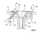
FIGURE 2 shows schematic cross sectional view of part of the shredder arrangement offigure 1 in more detail, with the protective guard in a retracted, non-operative position; -
FIGURE 3 shows a schematic perspective view corresponding toFigure 2 ; -
FIGURE 4 shows a schematic cross-sectional view corresponding toFigure 2 , but with the protective guard in an operative position; -
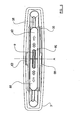
FIGURE 5 shows a schematic plan view corresponding toFigure 4 , illustrating the protective guard in a first configuration; -
FIGURE 6 shows a schematic plan view corresponding toFigure 4 , but illustrating the guard in a second configuration. -
Figure 1 shows ashredder arrangement 1 comprising ahousing 2 which incorporates afeed slot assembly 3 defining anelongate feed slot 3a. Thefeed slot 3a is suitable for receiving sheet material inserted by a user, including paper, CDs and credit cards. A motor-driven rotary cutting mechanism 4 (shown only schematically inFigure 1 ) is located within thehousing 2, directly below thefeed slot 3a, whereby sheet material fed through thefeed slot 3 engages, and is shredded by, thecutting mechanism 4. The configuration and operation of the cutting mechanism may be entirely conventional, and various forms of cutting mechanism will readily be appreciated by the skilled person. - The
entire housing 2 may be mounted, in conventional manner, on some sort of bin, which collects the shredded material beneath thecutting mechanism 4; alternatively, the housing may itself define a bin region, below the cutting mechanism, again in conventional manner. - It will be appreciated to those skilled in the art that the
shredder arrangement 1 may optionally include a whole manner of other features such as, for example, an auto-start sensor (not shown) to energise the cutting mechanism automatically once sheet material is inserted through thefeed slot 3a. - However, in the interests of conciseness, no detailed description of features which do not specifically relate to the invention is included here.
-
Figures 2 and3 show thefeed slot assembly 3 in more detail, with the remainder of theshredder arrangement 1 omitted for clarity. - The
feed slot assembly 3 comprises anelongate body portion 3b which defines theelongate feed slot 3a. - The shape of the
elongate body portion 3b may be conveniently thought of in terms of a conventional circular funnel which has been stretched along one axis to form an elongate, oval funnel. - Thus, referring to
Figure 2 in particular, which shows thebody portion 3b in cross-section, thebody portion 3b comprises a laterally extending peripheral flange portion 3c, an upper elongate,circumferential wall section 3d which tapers downwardly from the inner edge of the flange portion 3c at a relatively shallow angle to the horizontal, and a lower elongate,circumferential wall section 3e depending from the lower edge of theupper wall section 3d and tapering downwardly at a relatively steep angle to the horizontal. The upper and lower circumferential wall sections thus effectively define a two-step downwardly tapering circumferential wall for thefeed slot 3a. - As shown most clearly in
Figure 3 , the inner edge of the peripheral flange portion 3c is recessed to form a pair of correspondingelongate shoulder portions feed slot 3a, and is further recessed, at the centre of eachshoulder portion small finger recesses shoulder portion 5a is provided with an elongate slot 5c, extending along the full length of theshoulder 5a, alongside the mouth of thefeed slot 3a. - Still referring to
Figures 2 and3 , the feed slot assembly is further provided with an elongate protective guard 7, which extends through the slot 5c in theshoulder 5a and which, inFigures 2 and3 , is shown in its non-operative, retracted position within the housing, away from thefeed slot 3a. - As best seen in
Figure 3 , the protective guard 7 has a generally "S-shaped" cross section and comprises a generally flat, rectangularbase panel portion 7a which extends through the slot 5c, and two oppositely directed "return"portions 7b, 7c located either side of the slot 5c, the latter "return" portion further including a pair of outwardly extending lugs 8 (of which only one is shown inFigure 3 ). The length of thebase portion 7a is very slightly less than the length of theshoulder portions - Still referring principally to
Figure 3 , thebase panel portion 7a further incorporates anelongate guide slot 7d extending along the central longitudinal axis of the guard 7 (substantially parallel with thefeed slot 3a). For reasons which will become apparent below, theguide slot 7d is slightly longer than the diameter of a standard CD, so that a standard CD could, in principle, be inserted through theguide slot 7d with a little room to spare on either side of the CD. - As best shown in
Figure 3 , a pair of identical generally "C-shaped"guard members base panel portion 7a for sliding movement relative to thebase panel portion 7a, along theguide slot 7d. - Thus, each of the "C-shaped"
guard members guide slot 7d and slidably engages theguide slot 7d to allow theguard members guide slot 7d, relative to one another, over the upper surface of thebase panel portion 7a. - It will be appreciated that the outer edges of the
guide slot 7d effectively act as "stops" for the (sliding) tabs, preventing further outward sliding movement of theguard members base panel portion 7a. In a similar manner, additional stop elements (not shown) are provided on the underside of the base panel portion which prevent theguard members Fig 3 ) of thebase panel portion 7a. - There are therefore two configurations for the pair of
guard members Fig 3 ), and the pair ofguide members - In the first such symmetric configuration, both of the
guard members base panel portion 7a. In this configuration, theguard members guide slot 7d to form afirst aperture 9 through the guard 7. - To move from the first symmetric configuration to the second symmetric configuration, each of the
guard members guide slot 7d until the respective tabs engage with the respective outer ends of theelongate guide slot 7d, so that eachguard member guard members Fig 6 ) through the guard 7. - The dimensions of the
guard members elongate guide slot 7d are selected such that the size of theaperture 9 is slightly larger than the cross-section of a standard "credit-card" sized card, whilst the size of the secondalternative aperture 10 is slightly larger than the cross-section of a standard CD. - It is to be noted that the guard 7 is not positively secured to the
body portion 3b of the feed slot assembly in any way, but rather is effectively "floating" in relation to the feed slot assembly 3 (and housing 2). Thus, in the "retracted", non-operative position shown inFigure 2 , the guard 7 effectively "hangs" freely from thebody portion 3b (specifically the peripheral flange portion 3c), with thereturn portion 7b preventing the guard 7 from 'falling' down through the slot 5c. Thereturn portion 7b is specifically configured so that, when the guard 7 is 'hanging' in its retracted position, thereturn portion 7b effectively forms a continuation of uppercircumferential wall portion 3d (seeFig 2 ). - On the other hand, it will be appreciated that, by manually grasping the
return portion 7b (in the region of thefinger recess 6a), a user may nevertheless manually pull the guard 7 up through the slot 5c in the direction A (seeFigure 2 ), whereby the radius of the return portion 7c will eventually engage the peripheral flange portion 3c, causing the guard 7 to pivot in the direction B (seeFigure2 ). In this manner, when shredding relatively rigid sheet material, a user can conveniently move the guard 7 from the retracted, non-operative position shown inFigure 2 to the operative position shown inFigures 4 and5 , where the guard 7 extends centrally across thefeed slot 3a, and engages theshoulder portions - It will be appreciated, referring to
Figures 4 and5 , that the guard 7 is effectively retained in the operative position until such time as the user manually moves the guard 7 back to the 'hanging' retracted position. Thus, theshoulder portions feed slot 3a). At the same time, thelugs 8 effectively prevent the guard 7 from being pulled or pushed upwardly through the slot 5c. - Once the guard 7 has been manually moved to the position shown in
Figure 4 , the guard 7 can then be manually adjusted between two configurations, depending upon the particular relatively rigid sheet material to be shredded. - Thus, referring to
Figure 5 , the first configuration for the guard 7 corresponds to the first symmetric configuration for the pair ofguard members first aperture 9 is formed through the guard 7. With the guard 7 in this configuration, credit-card sized articles may be inserted through theaperture 9 in the guard 7 and fed into thefeed slot 3a for shredding by thecutting mechanism 4, whilst the guard 7 protects the user against flying fragments of rigid sheet material being thrown upwardly through thefeed slot 3a. - In the case where a user desires to shred CDs or CD-sized articles, the guard 7 can be manually adjusted to its second configuration shown in
Figure 6 , corresponding to the second symmetric configuration for the pair ofguard members alternative aperture 10 is formed through the guard 7. With the guard 7 adjusted to this second configuration, CDs or the like can be inserted through thelarger aperture 10 in the guard 7 and fed into thefeed slot 3a for shredding by thecutting mechanism 4. Again, the guard 7 will protect the user against fragments of rigid sheet material being thrown upwardly through thefeed slot 3a. Here, it is to be noted that, in the second configuration, theguard members feed slot 3a, so that theguard 7a extends substantially entirely across the entire area of thefeed slot 3a. - It should be noted that, as the two configurations for the pair of
guard members aperture 9 toaperture 10 and vice versa. In this manner, the guard 7 provides for adjustment between two aperture sizes, whilst still ensuring that each aperture is 'centralised' above thefeed slot 3a andcutting mechanism 4. - Nevertheless, it will be appreciated that, where it is desired to shred relatively flexible material such as, for example, paper or the like, the guard 7 can be retract and stowed away in the position shown in
Figure 3 , away from the slot. With the guard in this position, paper can be shredded inserted into thefeed slot 3a in the normal manner, whilst thereturn portion 7b (forming a continuation of the wall portion 3c) eases the feeding of sheet material into thefeed slot 3a. - Whilst the guard 7 is a "floating" guard, which may be retracted into the housing when not in use, it is envisaged that the guard could actually be entirely removable from the shredder, so that the user could simply place the guard across the feed slot as and when required. When not in use, the guard could simply be stowed away in a drawer, preferably in the shredder housing itself.
- It will be appreciated that, whilst the present embodiment is directed towards use with CDs and credit cards, and
apertures apertures - When used in this specification and claims, the terms "comprises" and "comprising" and variations thereof mean that the specified features, steps or integers are included. The terms are not to be interpreted to exclude the presence of other features, steps or components.
- The features disclosed in the foregoing description, or the following claims, or the accompanying drawings, expressed in their specific forms or in terms of a means for performing the disclosed function, or a method or process for attaining the disclosed result, as appropriate, may, separately, or in any combination of such features, be utilised for realising the invention in diverse forms thereof.
Claims (8)
- A shredder arrangement (1) comprising:i) a housing (2) defining a feed slot (3a) for receiving sheet material inserted by a user;ii) a cutting mechanism (4) for shredding the sheet material inserted through the feed slot (3a); andiii) a protective guard (7) for positioning across the feed slot (3a) to prevent relatively rigid sheet material from striking the user during shredding of such sheet material, the guard (7) defining an aperture (9) allowing said sheet material to be inserted through the guard (7) and into the feed slot (3a);characterized in that :the protective guard (7) is moveable between a first configuration and a second configuration to symmetrically adjust the size of the aperture (9).
- A shredder arrangement (1) according to claim 1, wherein the protective guard (7) is manually moveable to adjust the size of the aperture (9).
- A shredder arrangement (1) according to claim 1 or 2 wherein, when the guard (1) is in the first configuration, the size of the aperture (9) corresponds to the cross-section of a standard credit card and, when the guard (7) is in the second configuration, the size of the aperture (9) corresponds to the cross-section of a standard Compact Disc.
- A shredder arrangement (1) according to any preceding claim, wherein the protective guard (7) is mounted to the housing for selective movement between a non-operative position, away from the feed slot (3a), and an operative position, across the feed slot (3a).
- A shredder arrangement (1) according to claim 4, wherein in the non-operative position, the protective guard (7) is at least partially retracted within the housing (2).
- A shredder arrangement (1) according to claim 3, wherein when the guard (7) is in the second configuration, the guard (7) extends across substantially the entire area of the feed slot (3a).
- A shredder arrangement (1) according to claim 6, wherein the guard (7) further extends across substantially the entire area of the feed slot (3a) when the guard (7) is in the first configuration.
- A shredder arrangement (1) according to any preceding claim, wherein the guard (7) comprises two guard members (8a, 8b) which together define the aperture (9), the guard members being slidable relative to one another for
symmetrically adjusting the size of the aperture (9).
Applications Claiming Priority (1)
| Application Number | Priority Date | Filing Date | Title |
|---|---|---|---|
| GB0700758A GB2445543B (en) | 2007-01-15 | 2007-01-15 | A shredder arrangement |
Publications (2)
| Publication Number | Publication Date |
|---|---|
| EP1944086A1 EP1944086A1 (en) | 2008-07-16 |
| EP1944086B1 true EP1944086B1 (en) | 2012-08-08 |
Family
ID=37809982
Family Applications (1)
| Application Number | Title | Priority Date | Filing Date |
|---|---|---|---|
| EP07022133A Active EP1944086B1 (en) | 2007-01-15 | 2007-11-14 | A shredder arrangement |
Country Status (3)
| Country | Link |
|---|---|
| US (1) | US7618001B2 (en) |
| EP (1) | EP1944086B1 (en) |
| GB (1) | GB2445543B (en) |
Families Citing this family (8)
| Publication number | Priority date | Publication date | Assignee | Title |
|---|---|---|---|---|
| GB2451513B (en) | 2007-08-02 | 2012-04-18 | Acco Uk Ltd | A shredding machine |
| US7819351B2 (en) * | 2007-09-26 | 2010-10-26 | Aron Abramson | Shredder head adapted to shred data bearing documents and bottles |
| USD686656S1 (en) | 2011-04-13 | 2013-07-23 | Acco Uk Limited | Shredder |
| USD686655S1 (en) | 2011-04-13 | 2013-07-23 | Acco Uk Limited | Shredder |
| US8967511B1 (en) * | 2012-12-01 | 2015-03-03 | Emily Lo | Slidable cover mechanism of a paper shredder |
| DE102019126015A1 (en) * | 2019-09-26 | 2021-04-01 | Acco Uk Ltd. | paper shredder |
| JP7524715B2 (en) * | 2020-10-29 | 2024-07-30 | セイコーエプソン株式会社 | Crushing Equipment |
| CN116510869B (en) * | 2023-05-16 | 2025-07-15 | 北银金融科技有限责任公司 | A bank card shredding device |
Family Cites Families (6)
| Publication number | Priority date | Publication date | Assignee | Title |
|---|---|---|---|---|
| JPH0319944Y2 (en) * | 1986-10-03 | 1991-04-26 | ||
| DE19912036A1 (en) * | 1999-03-17 | 2000-09-21 | Schleicher & Co Int | Crushing device for data carrier disks and disposal system therefor |
| US20040188553A1 (en) * | 2003-03-27 | 2004-09-30 | Hsien-Li Lo | Disc shredder |
| US7213780B2 (en) * | 2005-02-09 | 2007-05-08 | Aurora Global Investment Ltd. | Multifunctional paper shredder |
| DE202006014905U1 (en) * | 2006-09-28 | 2006-12-07 | Lo, Emily, Hsin Chuang City | Feed mechanism for file shredder comprises two rollers bearing against one another to seal inlet in normal rest position but forced apart by insertion of file and papers |
| US7398936B1 (en) * | 2007-01-05 | 2008-07-15 | Michilin Prosperity Co., Ltd. | Top and side loading shredder with optional handle |
-
2007
- 2007-01-15 GB GB0700758A patent/GB2445543B/en active Active
- 2007-11-14 EP EP07022133A patent/EP1944086B1/en active Active
- 2007-11-20 US US11/943,234 patent/US7618001B2/en active Active
Also Published As
| Publication number | Publication date |
|---|---|
| GB2445543B (en) | 2011-08-24 |
| US7618001B2 (en) | 2009-11-17 |
| EP1944086A1 (en) | 2008-07-16 |
| GB2445543A (en) | 2008-07-16 |
| US20080169370A1 (en) | 2008-07-17 |
| GB0700758D0 (en) | 2007-02-21 |
Similar Documents
| Publication | Publication Date | Title |
|---|---|---|
| US7618001B2 (en) | Shredder arrangement | |
| US7721982B2 (en) | File shredder with feed unit | |
| TW449533B (en) | An apparatus including a rotatable cutting member or a rotatable abrading member | |
| CN103495475B (en) | There is staple and the shredder of paperclip remover | |
| EP2010330B1 (en) | A shredding machine | |
| US7926753B2 (en) | Material and packaging shredding machine | |
| US20060157600A1 (en) | Paper shredder having a manual paper pressing device | |
| US20110198425A1 (en) | Auto feed shredder apparatus and methods | |
| CA1096349A (en) | Device for comminuting waste of different kinds, especially industrial waste and bulk refuse | |
| US7823814B2 (en) | Shredder head adapted to shred data bearing documents and bottles | |
| WO2008048637A1 (en) | A shredder | |
| US8061638B2 (en) | Shredder head adapted to shred data bearing documents and bottles | |
| US20120280070A1 (en) | Horizontally-fed paper shredder with turnover cover | |
| US8439286B2 (en) | Paper cleaning device for a shredder | |
| CN104646143A (en) | Leave crushing machine | |
| US20170087559A1 (en) | Safety shredder with jam clear | |
| CN119998070A (en) | Shutter cutting machine | |
| US20070295736A1 (en) | Wastebasket or bin having rocking springs at bottom | |
| ES2209713T3 (en) | CRUSHING DEVICE FOR MATERIAL TO BE CRUSHED BY CUTTING ACTION, WITH A ROTOR DISPOSED IN A HOUSING. | |
| CN201175674Y (en) | Substrate breaking device with common rotary axis | |
| JPH0749903B2 (en) | Ice breaker safety device | |
| JP3154631U (en) | shredder | |
| CN208788665U (en) | A kind of cutting edge for small kraut cutter and the vegetable-chopper using the blade | |
| KR102026143B1 (en) | Small Type Document Shredder | |
| JP2008055269A (en) | shredder |
Legal Events
| Date | Code | Title | Description |
|---|---|---|---|
| PUAI | Public reference made under article 153(3) epc to a published international application that has entered the european phase |
Free format text: ORIGINAL CODE: 0009012 |
|
| AK | Designated contracting states |
Kind code of ref document: A1 Designated state(s): AT BE BG CH CY CZ DE DK EE ES FI FR GB GR HU IE IS IT LI LT LU LV MC MT NL PL PT RO SE SI SK TR |
|
| AX | Request for extension of the european patent |
Extension state: AL BA HR MK RS |
|
| 17P | Request for examination filed |
Effective date: 20090115 |
|
| 17Q | First examination report despatched |
Effective date: 20090216 |
|
| AKX | Designation fees paid |
Designated state(s): AT BE BG CH CY CZ DE DK EE ES FI FR GB GR HU IE IS IT LI LT LU LV MC MT NL PL PT RO SE SI SK TR |
|
| GRAP | Despatch of communication of intention to grant a patent |
Free format text: ORIGINAL CODE: EPIDOSNIGR1 |
|
| GRAS | Grant fee paid |
Free format text: ORIGINAL CODE: EPIDOSNIGR3 |
|
| GRAA | (expected) grant |
Free format text: ORIGINAL CODE: 0009210 |
|
| AK | Designated contracting states |
Kind code of ref document: B1 Designated state(s): AT BE BG CH CY CZ DE DK EE ES FI FR GB GR HU IE IS IT LI LT LU LV MC MT NL PL PT RO SE SI SK TR |
|
| REG | Reference to a national code |
Ref country code: GB Ref legal event code: FG4D |
|
| REG | Reference to a national code |
Ref country code: AT Ref legal event code: REF Ref document number: 569456 Country of ref document: AT Kind code of ref document: T Effective date: 20120815 Ref country code: CH Ref legal event code: EP |
|
| REG | Reference to a national code |
Ref country code: IE Ref legal event code: FG4D |
|
| REG | Reference to a national code |
Ref country code: DE Ref legal event code: R096 Ref document number: 602007024488 Country of ref document: DE Effective date: 20120927 |
|
| REG | Reference to a national code |
Ref country code: NL Ref legal event code: VDEP Effective date: 20120808 |
|
| REG | Reference to a national code |
Ref country code: AT Ref legal event code: MK05 Ref document number: 569456 Country of ref document: AT Kind code of ref document: T Effective date: 20120808 |
|
| REG | Reference to a national code |
Ref country code: LT Ref legal event code: MG4D Effective date: 20120808 |
|
| PG25 | Lapsed in a contracting state [announced via postgrant information from national office to epo] |
Ref country code: FI Free format text: LAPSE BECAUSE OF FAILURE TO SUBMIT A TRANSLATION OF THE DESCRIPTION OR TO PAY THE FEE WITHIN THE PRESCRIBED TIME-LIMIT Effective date: 20120808 Ref country code: CY Free format text: LAPSE BECAUSE OF FAILURE TO SUBMIT A TRANSLATION OF THE DESCRIPTION OR TO PAY THE FEE WITHIN THE PRESCRIBED TIME-LIMIT Effective date: 20120808 Ref country code: LT Free format text: LAPSE BECAUSE OF FAILURE TO SUBMIT A TRANSLATION OF THE DESCRIPTION OR TO PAY THE FEE WITHIN THE PRESCRIBED TIME-LIMIT Effective date: 20120808 Ref country code: IS Free format text: LAPSE BECAUSE OF FAILURE TO SUBMIT A TRANSLATION OF THE DESCRIPTION OR TO PAY THE FEE WITHIN THE PRESCRIBED TIME-LIMIT Effective date: 20121208 Ref country code: AT Free format text: LAPSE BECAUSE OF FAILURE TO SUBMIT A TRANSLATION OF THE DESCRIPTION OR TO PAY THE FEE WITHIN THE PRESCRIBED TIME-LIMIT Effective date: 20120808 |
|
| PG25 | Lapsed in a contracting state [announced via postgrant information from national office to epo] |
Ref country code: LV Free format text: LAPSE BECAUSE OF FAILURE TO SUBMIT A TRANSLATION OF THE DESCRIPTION OR TO PAY THE FEE WITHIN THE PRESCRIBED TIME-LIMIT Effective date: 20120808 Ref country code: PL Free format text: LAPSE BECAUSE OF FAILURE TO SUBMIT A TRANSLATION OF THE DESCRIPTION OR TO PAY THE FEE WITHIN THE PRESCRIBED TIME-LIMIT Effective date: 20120808 Ref country code: BE Free format text: LAPSE BECAUSE OF FAILURE TO SUBMIT A TRANSLATION OF THE DESCRIPTION OR TO PAY THE FEE WITHIN THE PRESCRIBED TIME-LIMIT Effective date: 20120808 Ref country code: PT Free format text: LAPSE BECAUSE OF FAILURE TO SUBMIT A TRANSLATION OF THE DESCRIPTION OR TO PAY THE FEE WITHIN THE PRESCRIBED TIME-LIMIT Effective date: 20121210 Ref country code: SE Free format text: LAPSE BECAUSE OF FAILURE TO SUBMIT A TRANSLATION OF THE DESCRIPTION OR TO PAY THE FEE WITHIN THE PRESCRIBED TIME-LIMIT Effective date: 20120808 Ref country code: SI Free format text: LAPSE BECAUSE OF FAILURE TO SUBMIT A TRANSLATION OF THE DESCRIPTION OR TO PAY THE FEE WITHIN THE PRESCRIBED TIME-LIMIT Effective date: 20120808 Ref country code: GR Free format text: LAPSE BECAUSE OF FAILURE TO SUBMIT A TRANSLATION OF THE DESCRIPTION OR TO PAY THE FEE WITHIN THE PRESCRIBED TIME-LIMIT Effective date: 20121109 |
|
| PG25 | Lapsed in a contracting state [announced via postgrant information from national office to epo] |
Ref country code: NL Free format text: LAPSE BECAUSE OF FAILURE TO SUBMIT A TRANSLATION OF THE DESCRIPTION OR TO PAY THE FEE WITHIN THE PRESCRIBED TIME-LIMIT Effective date: 20120808 |
|
| PG25 | Lapsed in a contracting state [announced via postgrant information from national office to epo] |
Ref country code: ES Free format text: LAPSE BECAUSE OF FAILURE TO SUBMIT A TRANSLATION OF THE DESCRIPTION OR TO PAY THE FEE WITHIN THE PRESCRIBED TIME-LIMIT Effective date: 20121119 Ref country code: CZ Free format text: LAPSE BECAUSE OF FAILURE TO SUBMIT A TRANSLATION OF THE DESCRIPTION OR TO PAY THE FEE WITHIN THE PRESCRIBED TIME-LIMIT Effective date: 20120808 Ref country code: RO Free format text: LAPSE BECAUSE OF FAILURE TO SUBMIT A TRANSLATION OF THE DESCRIPTION OR TO PAY THE FEE WITHIN THE PRESCRIBED TIME-LIMIT Effective date: 20120808 Ref country code: DK Free format text: LAPSE BECAUSE OF FAILURE TO SUBMIT A TRANSLATION OF THE DESCRIPTION OR TO PAY THE FEE WITHIN THE PRESCRIBED TIME-LIMIT Effective date: 20120808 Ref country code: EE Free format text: LAPSE BECAUSE OF FAILURE TO SUBMIT A TRANSLATION OF THE DESCRIPTION OR TO PAY THE FEE WITHIN THE PRESCRIBED TIME-LIMIT Effective date: 20120808 |
|
| PG25 | Lapsed in a contracting state [announced via postgrant information from national office to epo] |
Ref country code: IT Free format text: LAPSE BECAUSE OF FAILURE TO SUBMIT A TRANSLATION OF THE DESCRIPTION OR TO PAY THE FEE WITHIN THE PRESCRIBED TIME-LIMIT Effective date: 20120808 Ref country code: SK Free format text: LAPSE BECAUSE OF FAILURE TO SUBMIT A TRANSLATION OF THE DESCRIPTION OR TO PAY THE FEE WITHIN THE PRESCRIBED TIME-LIMIT Effective date: 20120808 |
|
| PLBE | No opposition filed within time limit |
Free format text: ORIGINAL CODE: 0009261 |
|
| STAA | Information on the status of an ep patent application or granted ep patent |
Free format text: STATUS: NO OPPOSITION FILED WITHIN TIME LIMIT |
|
| REG | Reference to a national code |
Ref country code: CH Ref legal event code: PL |
|
| 26N | No opposition filed |
Effective date: 20130510 |
|
| PG25 | Lapsed in a contracting state [announced via postgrant information from national office to epo] |
Ref country code: CH Free format text: LAPSE BECAUSE OF NON-PAYMENT OF DUE FEES Effective date: 20121130 Ref country code: BG Free format text: LAPSE BECAUSE OF FAILURE TO SUBMIT A TRANSLATION OF THE DESCRIPTION OR TO PAY THE FEE WITHIN THE PRESCRIBED TIME-LIMIT Effective date: 20121108 Ref country code: LI Free format text: LAPSE BECAUSE OF NON-PAYMENT OF DUE FEES Effective date: 20121130 |
|
| REG | Reference to a national code |
Ref country code: IE Ref legal event code: MM4A |
|
| REG | Reference to a national code |
Ref country code: DE Ref legal event code: R097 Ref document number: 602007024488 Country of ref document: DE Effective date: 20130510 |
|
| PG25 | Lapsed in a contracting state [announced via postgrant information from national office to epo] |
Ref country code: IE Free format text: LAPSE BECAUSE OF NON-PAYMENT OF DUE FEES Effective date: 20121114 |
|
| PG25 | Lapsed in a contracting state [announced via postgrant information from national office to epo] |
Ref country code: MT Free format text: LAPSE BECAUSE OF FAILURE TO SUBMIT A TRANSLATION OF THE DESCRIPTION OR TO PAY THE FEE WITHIN THE PRESCRIBED TIME-LIMIT Effective date: 20120808 |
|
| PGFP | Annual fee paid to national office [announced via postgrant information from national office to epo] |
Ref country code: FR Payment date: 20131118 Year of fee payment: 7 |
|
| PG25 | Lapsed in a contracting state [announced via postgrant information from national office to epo] |
Ref country code: MC Free format text: LAPSE BECAUSE OF NON-PAYMENT OF DUE FEES Effective date: 20121130 Ref country code: TR Free format text: LAPSE BECAUSE OF FAILURE TO SUBMIT A TRANSLATION OF THE DESCRIPTION OR TO PAY THE FEE WITHIN THE PRESCRIBED TIME-LIMIT Effective date: 20120808 |
|
| PG25 | Lapsed in a contracting state [announced via postgrant information from national office to epo] |
Ref country code: LU Free format text: LAPSE BECAUSE OF NON-PAYMENT OF DUE FEES Effective date: 20121114 |
|
| PG25 | Lapsed in a contracting state [announced via postgrant information from national office to epo] |
Ref country code: HU Free format text: LAPSE BECAUSE OF FAILURE TO SUBMIT A TRANSLATION OF THE DESCRIPTION OR TO PAY THE FEE WITHIN THE PRESCRIBED TIME-LIMIT Effective date: 20071114 |
|
| REG | Reference to a national code |
Ref country code: FR Ref legal event code: ST Effective date: 20150731 |
|
| PG25 | Lapsed in a contracting state [announced via postgrant information from national office to epo] |
Ref country code: FR Free format text: LAPSE BECAUSE OF NON-PAYMENT OF DUE FEES Effective date: 20141201 |
|
| PGFP | Annual fee paid to national office [announced via postgrant information from national office to epo] |
Ref country code: DE Payment date: 20251022 Year of fee payment: 19 |
|
| PGFP | Annual fee paid to national office [announced via postgrant information from national office to epo] |
Ref country code: GB Payment date: 20251023 Year of fee payment: 19 |