EP1943987A2 - Implant with one-piece swivel joint - Google Patents
Implant with one-piece swivel joint Download PDFInfo
- Publication number
- EP1943987A2 EP1943987A2 EP08101635A EP08101635A EP1943987A2 EP 1943987 A2 EP1943987 A2 EP 1943987A2 EP 08101635 A EP08101635 A EP 08101635A EP 08101635 A EP08101635 A EP 08101635A EP 1943987 A2 EP1943987 A2 EP 1943987A2
- Authority
- EP
- European Patent Office
- Prior art keywords
- implant according
- base body
- axis
- load
- load axis
- Prior art date
- Legal status (The legal status is an assumption and is not a legal conclusion. Google has not performed a legal analysis and makes no representation as to the accuracy of the status listed.)
- Granted
Links
Images


Classifications
-
- A—HUMAN NECESSITIES
- A61—MEDICAL OR VETERINARY SCIENCE; HYGIENE
- A61F—FILTERS IMPLANTABLE INTO BLOOD VESSELS; PROSTHESES; DEVICES PROVIDING PATENCY TO, OR PREVENTING COLLAPSING OF, TUBULAR STRUCTURES OF THE BODY, e.g. STENTS; ORTHOPAEDIC, NURSING OR CONTRACEPTIVE DEVICES; FOMENTATION; TREATMENT OR PROTECTION OF EYES OR EARS; BANDAGES, DRESSINGS OR ABSORBENT PADS; FIRST-AID KITS
- A61F2/00—Filters implantable into blood vessels; Prostheses, i.e. artificial substitutes or replacements for parts of the body; Appliances for connecting them with the body; Devices providing patency to, or preventing collapsing of, tubular structures of the body, e.g. stents
- A61F2/02—Prostheses implantable into the body
- A61F2/30—Joints
- A61F2/44—Joints for the spine, e.g. vertebrae, spinal discs
- A61F2/442—Intervertebral or spinal discs, e.g. resilient
-
- A—HUMAN NECESSITIES
- A61—MEDICAL OR VETERINARY SCIENCE; HYGIENE
- A61B—DIAGNOSIS; SURGERY; IDENTIFICATION
- A61B17/00—Surgical instruments, devices or methods, e.g. tourniquets
- A61B17/56—Surgical instruments or methods for treatment of bones or joints; Devices specially adapted therefor
- A61B17/58—Surgical instruments or methods for treatment of bones or joints; Devices specially adapted therefor for osteosynthesis, e.g. bone plates, screws, setting implements or the like
- A61B17/68—Internal fixation devices, including fasteners and spinal fixators, even if a part thereof projects from the skin
- A61B17/70—Spinal positioners or stabilisers ; Bone stabilisers comprising fluid filler in an implant
- A61B17/7001—Screws or hooks combined with longitudinal elements which do not contact vertebrae
- A61B17/7002—Longitudinal elements, e.g. rods
- A61B17/7019—Longitudinal elements having flexible parts, or parts connected together, such that after implantation the elements can move relative to each other
- A61B17/7026—Longitudinal elements having flexible parts, or parts connected together, such that after implantation the elements can move relative to each other with a part that is flexible due to its form
-
- A—HUMAN NECESSITIES
- A61—MEDICAL OR VETERINARY SCIENCE; HYGIENE
- A61F—FILTERS IMPLANTABLE INTO BLOOD VESSELS; PROSTHESES; DEVICES PROVIDING PATENCY TO, OR PREVENTING COLLAPSING OF, TUBULAR STRUCTURES OF THE BODY, e.g. STENTS; ORTHOPAEDIC, NURSING OR CONTRACEPTIVE DEVICES; FOMENTATION; TREATMENT OR PROTECTION OF EYES OR EARS; BANDAGES, DRESSINGS OR ABSORBENT PADS; FIRST-AID KITS
- A61F2/00—Filters implantable into blood vessels; Prostheses, i.e. artificial substitutes or replacements for parts of the body; Appliances for connecting them with the body; Devices providing patency to, or preventing collapsing of, tubular structures of the body, e.g. stents
- A61F2/02—Prostheses implantable into the body
- A61F2/28—Bones
-
- A—HUMAN NECESSITIES
- A61—MEDICAL OR VETERINARY SCIENCE; HYGIENE
- A61F—FILTERS IMPLANTABLE INTO BLOOD VESSELS; PROSTHESES; DEVICES PROVIDING PATENCY TO, OR PREVENTING COLLAPSING OF, TUBULAR STRUCTURES OF THE BODY, e.g. STENTS; ORTHOPAEDIC, NURSING OR CONTRACEPTIVE DEVICES; FOMENTATION; TREATMENT OR PROTECTION OF EYES OR EARS; BANDAGES, DRESSINGS OR ABSORBENT PADS; FIRST-AID KITS
- A61F2/00—Filters implantable into blood vessels; Prostheses, i.e. artificial substitutes or replacements for parts of the body; Appliances for connecting them with the body; Devices providing patency to, or preventing collapsing of, tubular structures of the body, e.g. stents
- A61F2/02—Prostheses implantable into the body
- A61F2/30—Joints
- A61F2/44—Joints for the spine, e.g. vertebrae, spinal discs
-
- A—HUMAN NECESSITIES
- A61—MEDICAL OR VETERINARY SCIENCE; HYGIENE
- A61B—DIAGNOSIS; SURGERY; IDENTIFICATION
- A61B17/00—Surgical instruments, devices or methods, e.g. tourniquets
- A61B17/56—Surgical instruments or methods for treatment of bones or joints; Devices specially adapted therefor
- A61B17/58—Surgical instruments or methods for treatment of bones or joints; Devices specially adapted therefor for osteosynthesis, e.g. bone plates, screws, setting implements or the like
- A61B17/68—Internal fixation devices, including fasteners and spinal fixators, even if a part thereof projects from the skin
- A61B17/70—Spinal positioners or stabilisers ; Bone stabilisers comprising fluid filler in an implant
- A61B17/7001—Screws or hooks combined with longitudinal elements which do not contact vertebrae
- A61B17/7002—Longitudinal elements, e.g. rods
- A61B17/7004—Longitudinal elements, e.g. rods with a cross-section which varies along its length
-
- A—HUMAN NECESSITIES
- A61—MEDICAL OR VETERINARY SCIENCE; HYGIENE
- A61B—DIAGNOSIS; SURGERY; IDENTIFICATION
- A61B17/00—Surgical instruments, devices or methods, e.g. tourniquets
- A61B17/56—Surgical instruments or methods for treatment of bones or joints; Devices specially adapted therefor
- A61B17/58—Surgical instruments or methods for treatment of bones or joints; Devices specially adapted therefor for osteosynthesis, e.g. bone plates, screws, setting implements or the like
- A61B17/68—Internal fixation devices, including fasteners and spinal fixators, even if a part thereof projects from the skin
- A61B17/70—Spinal positioners or stabilisers ; Bone stabilisers comprising fluid filler in an implant
- A61B17/7001—Screws or hooks combined with longitudinal elements which do not contact vertebrae
- A61B17/7035—Screws or hooks, wherein a rod-clamping part and a bone-anchoring part can pivot relative to each other
- A61B17/7037—Screws or hooks, wherein a rod-clamping part and a bone-anchoring part can pivot relative to each other wherein pivoting is blocked when the rod is clamped
-
- A—HUMAN NECESSITIES
- A61—MEDICAL OR VETERINARY SCIENCE; HYGIENE
- A61B—DIAGNOSIS; SURGERY; IDENTIFICATION
- A61B17/00—Surgical instruments, devices or methods, e.g. tourniquets
- A61B17/56—Surgical instruments or methods for treatment of bones or joints; Devices specially adapted therefor
- A61B17/58—Surgical instruments or methods for treatment of bones or joints; Devices specially adapted therefor for osteosynthesis, e.g. bone plates, screws, setting implements or the like
- A61B17/68—Internal fixation devices, including fasteners and spinal fixators, even if a part thereof projects from the skin
- A61B17/84—Fasteners therefor or fasteners being internal fixation devices
- A61B17/86—Pins or screws or threaded wires; nuts therefor
-
- A—HUMAN NECESSITIES
- A61—MEDICAL OR VETERINARY SCIENCE; HYGIENE
- A61F—FILTERS IMPLANTABLE INTO BLOOD VESSELS; PROSTHESES; DEVICES PROVIDING PATENCY TO, OR PREVENTING COLLAPSING OF, TUBULAR STRUCTURES OF THE BODY, e.g. STENTS; ORTHOPAEDIC, NURSING OR CONTRACEPTIVE DEVICES; FOMENTATION; TREATMENT OR PROTECTION OF EYES OR EARS; BANDAGES, DRESSINGS OR ABSORBENT PADS; FIRST-AID KITS
- A61F2/00—Filters implantable into blood vessels; Prostheses, i.e. artificial substitutes or replacements for parts of the body; Appliances for connecting them with the body; Devices providing patency to, or preventing collapsing of, tubular structures of the body, e.g. stents
- A61F2/02—Prostheses implantable into the body
- A61F2/30—Joints
- A61F2/44—Joints for the spine, e.g. vertebrae, spinal discs
- A61F2/442—Intervertebral or spinal discs, e.g. resilient
- A61F2/4425—Intervertebral or spinal discs, e.g. resilient made of articulated components
-
- A—HUMAN NECESSITIES
- A61—MEDICAL OR VETERINARY SCIENCE; HYGIENE
- A61F—FILTERS IMPLANTABLE INTO BLOOD VESSELS; PROSTHESES; DEVICES PROVIDING PATENCY TO, OR PREVENTING COLLAPSING OF, TUBULAR STRUCTURES OF THE BODY, e.g. STENTS; ORTHOPAEDIC, NURSING OR CONTRACEPTIVE DEVICES; FOMENTATION; TREATMENT OR PROTECTION OF EYES OR EARS; BANDAGES, DRESSINGS OR ABSORBENT PADS; FIRST-AID KITS
- A61F2/00—Filters implantable into blood vessels; Prostheses, i.e. artificial substitutes or replacements for parts of the body; Appliances for connecting them with the body; Devices providing patency to, or preventing collapsing of, tubular structures of the body, e.g. stents
- A61F2/02—Prostheses implantable into the body
- A61F2/30—Joints
- A61F2002/30001—Additional features of subject-matter classified in A61F2/28, A61F2/30 and subgroups thereof
- A61F2002/30108—Shapes
- A61F2002/30199—Three-dimensional shapes
- A61F2002/30224—Three-dimensional shapes cylindrical
- A61F2002/30235—Three-dimensional shapes cylindrical tubular, e.g. sleeves
-
- A—HUMAN NECESSITIES
- A61—MEDICAL OR VETERINARY SCIENCE; HYGIENE
- A61F—FILTERS IMPLANTABLE INTO BLOOD VESSELS; PROSTHESES; DEVICES PROVIDING PATENCY TO, OR PREVENTING COLLAPSING OF, TUBULAR STRUCTURES OF THE BODY, e.g. STENTS; ORTHOPAEDIC, NURSING OR CONTRACEPTIVE DEVICES; FOMENTATION; TREATMENT OR PROTECTION OF EYES OR EARS; BANDAGES, DRESSINGS OR ABSORBENT PADS; FIRST-AID KITS
- A61F2/00—Filters implantable into blood vessels; Prostheses, i.e. artificial substitutes or replacements for parts of the body; Appliances for connecting them with the body; Devices providing patency to, or preventing collapsing of, tubular structures of the body, e.g. stents
- A61F2/02—Prostheses implantable into the body
- A61F2/30—Joints
- A61F2002/30001—Additional features of subject-matter classified in A61F2/28, A61F2/30 and subgroups thereof
- A61F2002/30316—The prosthesis having different structural features at different locations within the same prosthesis; Connections between prosthetic parts; Special structural features of bone or joint prostheses not otherwise provided for
- A61F2002/30535—Special structural features of bone or joint prostheses not otherwise provided for
- A61F2002/30565—Special structural features of bone or joint prostheses not otherwise provided for having spring elements
- A61F2002/30571—Leaf springs
-
- A—HUMAN NECESSITIES
- A61—MEDICAL OR VETERINARY SCIENCE; HYGIENE
- A61F—FILTERS IMPLANTABLE INTO BLOOD VESSELS; PROSTHESES; DEVICES PROVIDING PATENCY TO, OR PREVENTING COLLAPSING OF, TUBULAR STRUCTURES OF THE BODY, e.g. STENTS; ORTHOPAEDIC, NURSING OR CONTRACEPTIVE DEVICES; FOMENTATION; TREATMENT OR PROTECTION OF EYES OR EARS; BANDAGES, DRESSINGS OR ABSORBENT PADS; FIRST-AID KITS
- A61F2/00—Filters implantable into blood vessels; Prostheses, i.e. artificial substitutes or replacements for parts of the body; Appliances for connecting them with the body; Devices providing patency to, or preventing collapsing of, tubular structures of the body, e.g. stents
- A61F2/02—Prostheses implantable into the body
- A61F2/30—Joints
- A61F2/30767—Special external or bone-contacting surface, e.g. coating for improving bone ingrowth
- A61F2/30771—Special external or bone-contacting surface, e.g. coating for improving bone ingrowth applied in original prostheses, e.g. holes or grooves
- A61F2002/30772—Apertures or holes, e.g. of circular cross section
- A61F2002/30777—Oblong apertures
-
- A—HUMAN NECESSITIES
- A61—MEDICAL OR VETERINARY SCIENCE; HYGIENE
- A61F—FILTERS IMPLANTABLE INTO BLOOD VESSELS; PROSTHESES; DEVICES PROVIDING PATENCY TO, OR PREVENTING COLLAPSING OF, TUBULAR STRUCTURES OF THE BODY, e.g. STENTS; ORTHOPAEDIC, NURSING OR CONTRACEPTIVE DEVICES; FOMENTATION; TREATMENT OR PROTECTION OF EYES OR EARS; BANDAGES, DRESSINGS OR ABSORBENT PADS; FIRST-AID KITS
- A61F2/00—Filters implantable into blood vessels; Prostheses, i.e. artificial substitutes or replacements for parts of the body; Appliances for connecting them with the body; Devices providing patency to, or preventing collapsing of, tubular structures of the body, e.g. stents
- A61F2/02—Prostheses implantable into the body
- A61F2/30—Joints
- A61F2/30767—Special external or bone-contacting surface, e.g. coating for improving bone ingrowth
- A61F2/30771—Special external or bone-contacting surface, e.g. coating for improving bone ingrowth applied in original prostheses, e.g. holes or grooves
- A61F2002/30772—Apertures or holes, e.g. of circular cross section
- A61F2002/30784—Plurality of holes
- A61F2002/30787—Plurality of holes inclined obliquely with respect to each other
-
- A—HUMAN NECESSITIES
- A61—MEDICAL OR VETERINARY SCIENCE; HYGIENE
- A61F—FILTERS IMPLANTABLE INTO BLOOD VESSELS; PROSTHESES; DEVICES PROVIDING PATENCY TO, OR PREVENTING COLLAPSING OF, TUBULAR STRUCTURES OF THE BODY, e.g. STENTS; ORTHOPAEDIC, NURSING OR CONTRACEPTIVE DEVICES; FOMENTATION; TREATMENT OR PROTECTION OF EYES OR EARS; BANDAGES, DRESSINGS OR ABSORBENT PADS; FIRST-AID KITS
- A61F2/00—Filters implantable into blood vessels; Prostheses, i.e. artificial substitutes or replacements for parts of the body; Appliances for connecting them with the body; Devices providing patency to, or preventing collapsing of, tubular structures of the body, e.g. stents
- A61F2/02—Prostheses implantable into the body
- A61F2/30—Joints
- A61F2/30767—Special external or bone-contacting surface, e.g. coating for improving bone ingrowth
- A61F2/30771—Special external or bone-contacting surface, e.g. coating for improving bone ingrowth applied in original prostheses, e.g. holes or grooves
- A61F2002/30841—Sharp anchoring protrusions for impaction into the bone, e.g. sharp pins, spikes
-
- A—HUMAN NECESSITIES
- A61—MEDICAL OR VETERINARY SCIENCE; HYGIENE
- A61F—FILTERS IMPLANTABLE INTO BLOOD VESSELS; PROSTHESES; DEVICES PROVIDING PATENCY TO, OR PREVENTING COLLAPSING OF, TUBULAR STRUCTURES OF THE BODY, e.g. STENTS; ORTHOPAEDIC, NURSING OR CONTRACEPTIVE DEVICES; FOMENTATION; TREATMENT OR PROTECTION OF EYES OR EARS; BANDAGES, DRESSINGS OR ABSORBENT PADS; FIRST-AID KITS
- A61F2230/00—Geometry of prostheses classified in groups A61F2/00 - A61F2/26 or A61F2/82 or A61F9/00 or A61F11/00 or subgroups thereof
- A61F2230/0063—Three-dimensional shapes
- A61F2230/0069—Three-dimensional shapes cylindrical
Definitions
- the present invention relates to an implant for permanent or temporary transfer into the human or animal body according to the preamble of claim 1 or a placeholder for vertebral bodies, a disc replacement or a connecting rod for Pedikelschraubenan extracten and a stabilization system of these components.
- intervertebral discs can be replaced by corresponding wildcards, such as in the DE 43 23 034 C1 described.
- These placeholders which essentially have a cylindrical tube-shaped basic structure, must absorb substantially axial compressive forces in order to divert the load carried by the spinal column. For this purpose, a sufficient strength of the placeholder is required.
- the placeholders have some flexibility to accommodate movements of the spine, especially bends or twists.
- placeholders for vertebral bodies or intervertebral discs have been proposed according to the prior art, which realize a combination of the two functionalities, namely on the one hand strength, in particular in the axial compression direction, and on the other hand mobility, in particular bendability about a rotation axis perpendicular to the axle load direction.
- Examples for this are the DE 103 37 088 A1 as well as the WO 2005/039454 A2 ,
- a flexible area is provided in the middle area between the ends, which serve for arrangement or attachment in the adjacent tissue or adjacent vertebrae, which is achieved either by appropriate elastic materials or by a corresponding structure of the placeholder.
- the WO 2005/039454 proposes for this purpose to provide a spiral circumferential slot which gives the main body in the elastic central region a spring-like effect.
- WO 2005/039454 A2 discloses further that other implants, such as connecting rods for pedicle screw assemblies or similar stabilization systems, by appropriate helix shapes in addition to the ability to transmit forces may also have some flexibility.
- the present invention is based on the recognition that to improve a balanced ratio of flexibility or Mobility on the one hand and stiffness or strength and load capacity on the other hand defined hinges should be provided, on the one hand have a capacity for load transfer, for example in the axial load direction, but on the other hand allow rotation about the axis of rotation of the defined pivot joint and thus bending of the implant.
- Film hinge here means that a thin film or web portion or generally a wall portion is provided which allows by the dimensional design of a corresponding elasticity and thus rotational movement or pivotal movement, although the corresponding wall portion or the corresponding webs of the same, in particular itself rigid material are made, like the other areas.
- At least one such rotary joint is provided in order to allow tilting of the ends of the implant or bending at least in one direction.
- a plurality of hinges are provided, which are preferably arranged in different planes, in particular along the main load axis and twisted about the main load axis.
- a structure is preferred in which different axes of rotation are alternately offset in different planes by 90 ° to each other, so that a bending of the implant is ensured in each direction.
- the implant so that the substantially tubular, in particular cylindrical tube-shaped base body are constructed of a plurality of superimposed disc or ring elements, which are connected to each other by respective hinge or hinges, but otherwise arranged spaced from each other are such that there is a free path of movement in the rotation about the corresponding pivot joint.
- the hinges are each arranged along the bisectors of the individual ring or Scheibenelmente, while on both sides of the film hinge a recess connects, which provides the necessary space for movement.
- this slot-shaped spacing defines the possible tilting of adjacent disk or ring elements relative to one another and, at the same time, defines the potential mutual bearing surfaces which can serve for a load transfer during an axial compression along the main load axis of the implant.
- connecting means are preferably provided on the end plates or end disks or rings, which intervene and Ingression into adjacent body parts or attachment of the implant to other implant components allows.
- prongs, truncated spikes, depressions, recesses and the like are provided, which are also characterized in particular by the fact that they can be easily adapted by their design to a desired length.
- the film hinges are preferably formed so that, starting from the outer peripheral wall of the tubular body between the adjacent disc or ring elements radially inwardly extending webs are provided, which can be additionally connected by lateral plate elements with the corresponding disc or ring elements.
- the webs or film hinges are not carried out continuously, but there are two opposing webs are provided, which are spaced apart in the central region, so that along the central axis results in a through opening, which can be designed differently in their shape and structure, for example, cloverleaf, cruciform or the like.
- the material for the preferably integrally manufactured base body thus in particular the discs and rings or webs of the film hinges can be selected from different materials.
- all biocompatible metals, metal alloys or plastics are suitable here.
- Due to the structure of the basic body according to the invention very rigid materials can also be used per se, since the flexibility and mobility of the basic body is ensured by the structural design. Of course, however, it is also possible to use materials which inherently have a certain elasticity and thus ensure mobility and flexibility.
- Fig. 1 a perspective view of a placeholder according to the invention
- Fig. 2 a perspective view of a second blank according to the invention
- Fig. 3 a perspective view of a third blank according to the invention.
- Fig. 4 a side view of the placeholder Fig. 4 ;
- Fig. 5 a side view of the placeholder from the Fig. 1 and 4 , where the side view of Fig. 5 by 90 ° compared to that of Fig. 4 is turned;
- Fig. 6 a side view of the placeholder Fig. 3 ;
- Fig. 7 a side view of the placeholder from the Fig. 3 and 6 , where the side view of the placeholder in Fig. 7 by 90 ° compared to those from Fig. 6 is twisted;
- Fig. 8 a plan view of the placeholder Fig. 3 ;
- Fig. 9 a plan view of the placeholder Fig. 1 ;
- Fig. 10 a side view of part of the previously described placeholder in different load conditions in the sub-images a) to c);
- Fig. 11 a side view of part of the placeholder of the preceding examples in side view with a different in the sub-images a) to c) load;
- Fig. 12 a detailed view of the placeholder Fig. 1 ;
- Fig. 13 a lateral schematic representation of the placeholder Fig. 1 in interaction with a pedicle screw assembly
- Fig. 14 a lateral schematic representation of the interaction of the placeholder from Fig. 1 with another form of pedicle screw assembly
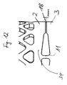
- Fig. 15 a schematic side view of the use of the placeholder from Fig. 3 ;
- Fig. 16 a lateral schematic representation of another use of the placeholder from Fig. 3 in cooperation with a pedicle screw assembly
- Fig. 17 a schematic side view of a connecting rod according to the invention.
- Fig. 18 a detailed view of the connecting rod according to the invention Fig. 17 in a partial sectional view;
- Fig. 19 a sectional view of the connecting rod FIGS. 17 and 18 ;
- Fig. 20 a perspective view of the connecting rod according to the invention from the Fig. 17 - 19 ;
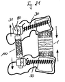
- Fig. 21 a schematic view of the use of the wildcard from the invention Fig. 1 and the connecting rod according to the invention Fig. 20 ,
- the Fig. 1 shows a perspective view of a first embodiment of an implant according to the invention in the form of a placeholder for the spine.
- the placeholder 1 has a substantially cylindrical tube-shaped base body, which is divided into six discs or rings 2 to 7, which are arranged one above the other along the longitudinal axis L, which is also the primary load axis L.
- the two end elements 2 and 7 have on the outwardly facing ends connecting elements 8 to 10, which are formed of blunt teeth, diamond-shaped or triangular recesses 9 and triangular depressions 10 between the blunt teeth.
- These connecting elements 8 to 10 serve to intervene and coalesce with adjacent tissue, cartilage or vertebral bodies. With the connecting elements 8 to 10 a secure arrangement of the placeholder 1 in the spine is guaranteed.
- the film hinges 11 to 15 do not extend completely to the central axis, which is parallel or identical to the load axis L, but are spaced apart from one another in the inner region, so that a continuous opening is formed, which will be explained later.
- the webs may be limited to a width corresponding to the wall thickness of the main body or the rings 2 to 7.
- the film hinges are alternately rotated by 90 °, so that the film hinge 11 is arranged perpendicular to the film hinge 12, while this is in turn arranged perpendicular to the film hinge 13, etc.
- the disks or ring elements 2 to 7 are connected to each other only by the respective film hinges 11 to 15, which separate two semicircular recesses between the corresponding disks or ring elements 2 to 7 from each other.
- the corresponding recesses have in the region of the film hinges 11 to 15 a greater thickness in the direction of the load axis L than in areas farther from the film hinges 11 to 15.
- the recesses between the disc or ring elements 2 to 7 are divided into two, wherein the first part forms a triangular in cross-section recess, starting from the webs of the film hinges 11 to 15 with a large thickness in the direction of the load axis with increasing distance from the Film hinges 11 to 15 decreases in thickness and finally expires in a second part in a thin slot 18 between the disc or ring elements 2 to 7.
- the substantially triangular shape in cross section of the recess 17 is optimized by rounded edges to the effect that no voltage spikes occur.
- FIGS. 2 and 3 Two further embodiments of a placeholder 1 'and 1 "are in perspective views of FIGS. 2 and 3 shown, wherein identical components are designated by identical reference numerals.
- the placeholder 1 ' has along the load axis L, are taken along the primary tensile and compressive forces of the placeholder 1', four disc or ring elements 2 ', 3', 4 'and 5'. These are connected to each other via hinges or film hinges 11, 12 and 13, wherein these each form rotational axes D perpendicular to the load axis L.
- Adjacent to the film hinges 11, 12 and 13 are provided on both sides of the webs of the film hinges 11 to 13 in cross-section substantially triangular recesses 17 which taper with increasing distance from the film hinges 11 to 13 and terminate in thin slots 18.
- cartilage or tissue are provided, being identical to the embodiment of Fig. 1 truncated spikes 8 and triangular recesses 10 are provided.
- disc elements 2 ", 3", 4 “and 5" are also connected to each other via alternately arranged, mutually perpendicular film hinges 11, 12 and 13, while in the other between the disc elements 2 ", 3", 4 “and 5" corresponding recesses are provided, which effect a spaced arrangement of the disc elements 2 ", 3", 4 “and 5" in the areas outside the film hinge.
- the distance between the writing elements 2 “, 3", 4 “and 5" is clear in the region of the triangular-shaped recess 17 in cross-section larger than in the area of the slot formation 18, here as well as in the other embodiments, approximately half of the circumference is provided in the region of the slot spacing, while the other half of the circumference has a greater distance between the disk elements 2 "to 5".
- FIGS. 4 to 7 illustrate again the constructive principle of the implant according to the invention by means of the placeholders 1 and 1 " FIGS. 4 and 5 two side views of the placeholder 1 are shown, which are rotated by 90 ° about the axis L to each other. It is clear in the comparison of FIGS. 4 and 5 to recognize that the film hinges 11, 13 and 15 on the one hand and the film hinges 12 and 14 on the other hand and the corresponding associated axes of rotation D are rotated by 90 ° to each other, through the slots 18 between the corresponding ring or Sclieibenelementen 2 to 7 a Tilting about the respective axes of rotation D is possible.
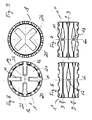
- FIGS. 8 and 9 show top views of the placeholders 1 "( FIG. 8 ) or 1 ( Fig. 9 ). It is clear from these plan views that both the placeholder 1 "and the placeholder 1 have a substantially cylindrical tube-shaped body which is constructed by the corresponding ring or disk elements and 12 of the wildcard 1 "in the Fig. 8 are formed by radially inwardly extending webs, which are executed in the middle but spaced from each other, so that there is a central opening 19 through the entire spacer 1 "along the load axis L is formed.
- the webs forming the film hinges can also laterally through corresponding plates 16 (see Fig. 1 ) stabilized or connected to the corresponding ring or disc elements 2 to 7.
- corresponding plates 16 see Fig. 1
- the films 16, as in the embodiment of Fig. 1 formed triangular, so results in a total in plan view, a cruciform continuous cavity 24, wherein the film hinges 11 to 15 forming webs in the region of the dashed lines 25 of Fig. 9 are arranged.
- FIGS. 10 and 11 show the mode of action of the structure according to the invention.
- the film hinge for example film hinge 12, or the corresponding webs is elastically compressed when an axial compressive force is applied along the primary load axis L.
- the axial load is absorbed not only by the webs of the film hinge 12, but also taken from the superimposed edge regions of the disk elements 3 and 4. In this way, the absorbable axial load is increased.
- the thin webs of the film hinge 12 allow a rotation about the axis perpendicular to the image plane. This way it comes to a one-sided investment of the edge regions of the disc elements 3 and 4 in the region of the slot formation 18 and a corresponding bending of the placeholder or tilting of the ends of the placeholder to each other. After this limited Verkipp- or Verbiege yogaeit it comes by the investment of the disc elements 3 and 4 together in the slot formation (see drawing b) Fig. 11 ) to a load transfer in the area of the slot formation, so that a further tilting is prevented and also with increasing load application stabilization by a correspondingly larger contact area (partial image c) Fig. 11 ) entry.
- FIGS. 10 and 11 It can be seen that a corresponding design of the recesses 17 and 18 between the disc or ring elements 3 and 4 allows adjustment of the possible Verkippungs- or bending region and the stability and strength of the entire implant. If the proportion of the slot area is increased overall, the result is a higher strength, since then more support surface is present. If the slot thickness, ie the distance of the discs, increased, the bendability increases.
- FIG. 12 illustrates again in detail the effect of the slot area between the ring or disc elements 2 and 3.
- the degree of mobility or tilting determined between the ring or disc elements 2 and 3.
- the size of the possible contact surface in the slot area 18 determines the size of the transferable load in the case of axial compression or corresponding bending.
- the formation of the ring or disc element 2 in the region 34 determines the bendability of the disc or the ring 2 and thus the elasticity in the direction of the load axis L.
- FIGS. 13 to 16 show different applications of inventive implants.
- Fig. 13 is the placeholder 1 in See in combination with a pedicle screw assembly, wherein the pedicle screws 30 are connected in the adjacent vertebral bodies at their screw heads 31 via a connecting rod 32 and exercise a stabilizing function.
- the connecting rod 32 is semi-rigid over its elasticity implied by the material.
- Fig. 14 shows the placeholder 1 in a similar application situation, wherein only in the Pedikelschraubenand eleven the semi-rigid connecting rod 32 is replaced by a flexible connecting rod 33, which in this case receives its flexibility by a helical spring-like construction with a core element.
- a connecting rod 33 and a connecting rod with the structure according to the invention of pivotally interconnected discs.
- FIGS. 15 and 16 show the field of application of the placeholder 1 ", once with stabilization device ( Fig. 16 ) and once without ( Fig. 15 ). Due to the smaller height of the placeholder 1 "here the placeholder is used as intervertebral disc replacement, again a stabilizing pedicle screw assembly with pedicle screws 30 and an elastic connecting rod 33 which is locked to the screw heads 31 may be provided.
- FIG. 17 shows a flexible connecting rod 100, which in a central region corresponding to the placeholder 1 basic body structure with articulated disc or ring elements 200, 300, 400 comprises, wherein the joints are alternately offset by 90 ° to each other.
- the joints are formed by film hinges 120, which are formed, for example, by corresponding connecting webs between the ring elements 200, 300, 400, the width of the webs 120 corresponding to the wall thickness of the rings 200, 300, 400.
- connecting rod 100 At the axial ends of the connecting rod 100 are connecting stub 80 for receiving in z. B screw heads provided by pedicle screws.
- the connecting pieces 80 When in the FIG. 17 shown Embodiment, the connecting pieces 80 have a smaller cross-section than the central region with the joint structure.
- rods are also conceivable, which have a consistently the same cross-section.
- FIG. 18 shows in a detailed view of the connecting rod 100 FIG. 17 in that in this case the corresponding ring elements 200 and 300 are likewise connected to one another only by corresponding web elements 120, while in the remaining wall region between the rings 200, 300 a bottle-shaped recess 170, 180 having a wide recess area 170 and a slot-shaped recess area 180 is provided.
- the shape of the recesses 170, 180 and in particular the thickness of the slot 180, in turn, the compressibility and the tiltability or flexibility of the connecting rod 100 is defined.
- FIG. 19 shows a sectional view of the connecting rod 100 of FIGS. 17 and 18 ,
- the connecting pieces 80 are integrally formed with the main body.
- FIG. 20 shows the flexible connecting rod 100 again in a perspective view, wherein it is clear that the cylinder tube-shaped basic structure with webs or hinges 120 hingedly connected ring members 200, 300,400 is constructed, wherein the webs or the film hinges of adjacent ring elements are each rotated by 90 ° to each other ,
- FIG. 21 shows an application for the inventive spacer 1 and the flexible connecting rod 100 and a stabilization system of a pedicle screw assembly.
- the screwed into the vertebral bodies pedicle screws 30 are connected to each other via the flexible connecting rod 100, wherein the connecting pieces 80 are received by the screw heads 31.
- Between the vertebral bodies of the placeholder 1 is provided.
- both the flexible configuration of the blank holder 1 and the connecting rod 100 are FIG. 21 indicated, a compression of the placeholder 1 with simultaneous elongation of the flexible connecting rod 100 or vice versa possible.
- both the flexible connection rod 100 and the flexible spacer 1 can perform corresponding bends or tilting of their axial ends. Overall, therefore, the desired requirements in terms of strength on the one hand and flexibility on the other hand can be ideally met.
- the present invention thus relates to an article having the following features:
- Implant for permanent or temporary transfer into the human or animal body with a base body for connecting spaced body parts and / or other implant components, which has a load axis (L) along which primarily tensile and / or compressive forces are transferable, transverse to the load axis at least an axis of rotation (D) is formed, which allows an at least limited bending of the base body about the axis of rotation, in particular of the arranged along the load axis ends of the base body, wherein the at least one axis of rotation by a hinge (11, 12, 13, 14, 15) is defined, which is integrally formed on the main body.
- L load axis
- D axis of rotation
- Implant according to the preceding features, wherein a plurality of rotary joints (11, 12, 13, 14, 15) with their axes of rotation in different planes transversely, in particular perpendicular to the load axis (L) are arranged.
- Implant according to the preceding features, wherein a plurality of rotary joints are provided with mutually about the load axis (L) twisted axes of rotation.
- Implant according to the preceding features, wherein a plurality of hinges (11, 12, 13, 14, 15) are provided in a plurality along the load axis superimposed planes, wherein alternately the hinges are offset from each other by 90 °.
- Implant according to the preceding features wherein the rotary joint (11, 12, 13, 14, 15) is designed in the form of a film hinge.
- Implant according to the preceding features wherein the rotary joint (11, 12, 13, 14, 15) by one, preferably two along the axis of rotation opposite, in a plane parallel to the load axis (L) extending webs is formed.
- Implant according to the preceding features wherein the rotary joint (11, 12, 13, 14, 15) by at least one, preferably two along the rotation axis opposite, extending from an outer peripheral wall of the base body in the direction of the load axis parallel to the central axis of the base body extending webs is formed.
- Implant according to the preceding features, wherein the base body in a plane perpendicular to the load axis (L), in which a hinge, in particular in the form of a perpendicular to this plane web is arranged, at least one, preferably two arranged on both sides of the roof joint recesses (17, 18), which allow tilting about the hinge.
- Implant according to the preceding features wherein the recess (17, 18), starting from the rotary joint (11, 12, 13, 14, 15) tapers at least in the wall region of the base body.
- Implant according to the preceding features, wherein the rotary joint (11, 12, 13, 14, 15) is arranged along a bisecting the main body.
- the base body at least two, preferably a plurality, each interconnected by a hinge discs or rings (2, 3, 4, 5, 6, 7).
- Implant according to the preceding features wherein the base body and in particular the discs or rings (2, 3, 4, 5, 6, 7) enclosed by the latter have a central, coaxial with the central axis arranged, along the load axis through opening (19 to 24).
- Implant according to one of the preceding features, wherein the opening (19 to 24) is star-shaped, cross-shaped or cloverleaf-shaped.
- Implant according to one of the preceding features, wherein two to ten, in particular two to six, preferably four to six discs or rings (2, 3, 4, 5, 6, 7) are provided.
- Implant according to one of the preceding features, wherein one to five, in particular three to five hinges (11, 12, 13, 14, 15) are provided.
- Implant according to one of the preceding features wherein the base body has an odd number of hinges (11, 12, 13, 14, 15) and an even number of discs or rings (2 to 7).
- Implant according to one of the preceding features, wherein the base body in the axial direction parallel to the load axis is elastically deformable, in particular compressible.
- Implant according to one of the preceding features wherein the disks or rings (2, 3, 4, 5, 6, 7) enclosed by the base body are designed such that predominantly they are elastically deformed under axial load along the load axis, in particular pressure load, in particular in the Be bent near the hinges.
- the base body is designed as a tube-like body with any cross-sectional shapes, in particular as a cylindrical tube-shaped body.
- Implant according to one of the preceding features, wherein the base body has at its arranged along the load axis ends connecting elements (8, 9, 10).
- connecting elements (8, 9, 10) are formed by openings, recesses, projections and / or teeth for engagement or ingrowth in adjacent body tissue.
- Intervertebral disc replacement according to one of the preceding features, wherein two to four discs or rings, which are connected to each other by means of one to three hinges, are provided.
- intervertebral disc replacement according to any one of the preceding features, wherein the connecting elements are formed by apertures, recesses, projections and / or prongs for engagement or ingrowth into adjacent body tissue.
- Stabilization system with one or more components comprising the components placeholder, disc replacement and connecting rod according to the preceding features.
Landscapes
- Health & Medical Sciences (AREA)
- Orthopedic Medicine & Surgery (AREA)
- Engineering & Computer Science (AREA)
- Biomedical Technology (AREA)
- Neurology (AREA)
- Life Sciences & Earth Sciences (AREA)
- Animal Behavior & Ethology (AREA)
- Veterinary Medicine (AREA)
- Heart & Thoracic Surgery (AREA)
- Public Health (AREA)
- General Health & Medical Sciences (AREA)
- Cardiology (AREA)
- Oral & Maxillofacial Surgery (AREA)
- Transplantation (AREA)
- Vascular Medicine (AREA)
- Surgery (AREA)
- Molecular Biology (AREA)
- Medical Informatics (AREA)
- Nuclear Medicine, Radiotherapy & Molecular Imaging (AREA)
- Prostheses (AREA)
- Surgical Instruments (AREA)
Abstract
Description
Die vorliegende Erfindung betrifft ein Implantat zur dauerhaften oder zeitweisen Verbringung in den menschlichen oder tierischen Körper gemäß dem Oberbegriff des Anspruchs 1 bzw. einen Platzhalter für Wirbelkörper, einen Bandscheibenersatz oder einen Verbindungsstab für Pedikelschraubenanordnungen sowie ein Stabilisierungssystem aus diesen Komponenten.The present invention relates to an implant for permanent or temporary transfer into the human or animal body according to the preamble of
In der modernen Medizin werden seit geraumer Zeit vielfältig Implantate verwendet, um nach Krankheiten, Verletzungen oder altersbedingten Abnutzungserscheinungen Teile des menschlichen Skeletts zu ersetzen. So ist es beispielsweise bekannt, bei Wirbelsäulenverletzungen, wie Brüchen oder bei einem Angriff von Teilen der Wirbelsäule durch einen Tumor, entsprechende Wirbelkörper durch Platzhalter zu ersetzen. Derartige Platzhalter sind beispielsweise in der europäischen Patentschrift
In ähnlicher Weise können auch Bandscheiben durch entsprechende Platzhalter ersetzt werden, wie beispielsweise in der
Darüber hinaus ist es jedoch wünschenswert, dass die Platzhalter eine gewisse Flexibilität aufweisen, um Bewegungen der Wirbelsäule, insbesondere Verbiegungen oder Verdrehungen mitzumachen. Zu diesem Zweck sind nach dem Stand der Technik Platzhalter für Wirbelkörper oder Bandscheiben vorgeschlagen worden, die eine Kombination der beiden Funktionalitäten, nämlich einerseits Festigkeit, insbesondere in axialer Druckrichtung, und andererseits Beweglichkeit, insbesondere Biegbarkeit um eine Drehachse senkrecht zur Achslastrichtung, realisieren. Beispiele hierfür sind die
Die
Obwohl mit diesen Lösungen sehr gute Ergebnisse hinsichtlich der erzielbaren Flexibilität erreicht werden, sind durch die Unbestimmtheit der Dreh- oder Biegeachsen derartiger Strukturen Defizite bezüglich der Festigkeit und der aufnehmbaren axialen Drucklast in Kauf zu nehmen.Although very good results in terms of achievable flexibility are achieved with these solutions, the uncertainty of the rotational or bending axes of such structures deficiencies in terms of strength and the absorbable axial pressure load to be accepted.
Es ist deshalb Aufgabe der vorliegenden Erfindung eine weitere Verbesserung des Eigenschaftsprofils hinsichtlich der an sich gegenläufigen Funktionalitäten, nämlich Flexibilität bzw. Beweglichkeit einerseits und Festigkeit bzw. Lastaufnahmefähigkeit andererseits, zu erzielen, wobei insgesamt das Implantat bzw. insbesondere der Platzhalter bei der Operation einfach einsetzbar und im übrigen einfach herstellbar sein soll.It is therefore an object of the present invention to achieve a further improvement of the property profile with respect to the opposing functionalities, namely flexibility or mobility on the one hand and strength or load-bearing capacity on the other hand, where the implant or in particular the placeholder in the operation easy to use and the rest should be easy to produce.
Diese Aufgabe wird gelöst mit einem Implantat mit den Merkmalen des Anspruchs 1. Vorteilhafte Ausgestaltungen sind Gegenstand der abhängigen Ansprüchen.This object is achieved with an implant having the features of
Die vorliegende Erfindung geht aus von der Erkenntnis, dass zur Verbesserung eines ausgewogenen Verhältnisses von Flexibilität bzw. Beweglichkeit einerseits und Steifigkeit bzw. Festigkeit und Lastaufnahmefähigkeit andererseits definierte Drehgelenke vorgesehen werden sollten, die einerseits eine Fähigkeit zur Lastübertragung, beispielsweise in axialer Lastrichtung, aufweisen, aber andererseits eine Drehung um die Drehachse des definierten Drehgelenks und somit Biegung des Implantats ermöglichen.The present invention is based on the recognition that to improve a balanced ratio of flexibility or Mobility on the one hand and stiffness or strength and load capacity on the other hand defined hinges should be provided, on the one hand have a capacity for load transfer, for example in the axial load direction, but on the other hand allow rotation about the axis of rotation of the defined pivot joint and thus bending of the implant.
Dies wird insbesondere dann möglich, wenn das Drehgelenk einstückig in dem Implantat ausgebildet wird, was vorzugsweise durch ein so genanntes Filmscharnier verwirklicht werden kann. Filmscharnier bedeutet hier, dass ein dünner Film- bzw. Stegbereich oder allgemein ein Wandbereich vorgesehen ist, der durch die dimensionale Auslegung eine entsprechende Elastizität und damit Drehbewegung bzw. Schwenkbewegung ermöglicht, obwohl der entsprechende Wandbereich oder die entsprechenden Stege aus dem gleichen, insbesondere an sich steifen Material gefertigt sind, wie die übrigen Bereiche.This is possible in particular when the rotary joint is formed integrally in the implant, which can preferably be realized by a so-called film hinge. Film hinge here means that a thin film or web portion or generally a wall portion is provided which allows by the dimensional design of a corresponding elasticity and thus rotational movement or pivotal movement, although the corresponding wall portion or the corresponding webs of the same, in particular itself rigid material are made, like the other areas.
Erfindungsgemäß ist mindestens ein derartiges Drehgelenk vorgesehen, um ein Verkippen der Enden des Implantats bzw. eine Verbiegung zumindest in eine Richtung zu ermöglichen. Vorzugsweise sind jedoch mehrere Drehgelenke vorgesehen, die vorzugsweise in verschiedenen Ebenen, insbesondere entlang der Hauptlastachse sowie verdreht um die Hauptlastachse angeordnet sind. Insbesondere wird eine Struktur bevorzugt, bei der verschiedene Drehachsen in verschiedenen Ebenen alternatierend um 90° zueinander versetzt sind, so dass eine Verbiegung des Implantats in jede Richtung gewährleistet wird.According to the invention, at least one such rotary joint is provided in order to allow tilting of the ends of the implant or bending at least in one direction. Preferably, however, a plurality of hinges are provided, which are preferably arranged in different planes, in particular along the main load axis and twisted about the main load axis. In particular, a structure is preferred in which different axes of rotation are alternately offset in different planes by 90 ° to each other, so that a bending of the implant is ensured in each direction.
Entsprechend ist es vorteilhaft, das Implantat so zu gestalten, dass der im wesentlichen rohrförmige, insbesondere zylinderrohrförmige Grundkörper aus mehreren übereinander angeordneten Scheiben- bzw. Ringelementen aufgebaut sind, die jeweils durch entsprechende Drehgelenk bzw. Filmscharniere miteinander verbunden sind, im übrigen aber beabstandet zueinander angeordnet sind, so dass ein freier Bewegungsweg bei der Drehung um das entsprechende Drehgelenk vorhanden ist.Accordingly, it is advantageous to make the implant so that the substantially tubular, in particular cylindrical tube-shaped base body are constructed of a plurality of superimposed disc or ring elements, which are connected to each other by respective hinge or hinges, but otherwise arranged spaced from each other are such that there is a free path of movement in the rotation about the corresponding pivot joint.
Vorzugsweise sind die Drehgelenke jeweils entlang der Halbierenden der einzelnen Ring- bzw. Scheibenelmente angeordnet, während sich beidseits des Filmscharniers eine Aussparung anschließt, die den notwendigen Bewegungsraum zur Verfügung stellt.Preferably, the hinges are each arranged along the bisectors of the individual ring or Scheibenelmente, while on both sides of the film hinge a recess connects, which provides the necessary space for movement.
Hier ist es vorteilhaft, wenn die Aussparung bzw. der Freiraum zwischen benachbarten Ring- bzw. Scheibenelementen, d.h. der Abstand zwischen diesen, ausgehend von dem Drehgelenk bzw. Filmscharnier abnimmt, so dass am Rand lediglich ein schlitzförmiger Abstand gegeben ist. Dieser schlitzförmige Abstand definiert einerseits die mögliche Verkippung benachbarter Scheiben- bzw. Ringelemente zueinander und definiert gleichzeitig bei einer axialen Stauchung entlang der Hauptlastachse des Implantats die potentiellen gegenseitigen Auflageflächen, die zu einer Lastabtragung dienen können. Dies führt dazu, dass bei einer axialen Druckbelastung entlang der Hauptlastachse zunächst das Drehgelenk bzw. Filmscharnier die Last aufnimmt. Durch die Ausgestaltung der über die Filmscharniere untereinander verbundenen Scheiben oder Ringe mit einer auf Grund der größeren Ausnehmungen geringeren Dicke der Scheiben oder Ringe in der Nähe der Filmscharniere, kommt es bei weiter zunehmender axialer Belastung zu einer elastischen Verformung bzw. insbesondere Verbiegung der Scheiben bzw. Ringe bis der schlitzförmige Abstand zwischen den benachbarten Scheiben- bzw. Ringelementen aufgebraucht ist. Sobald die benachbarten Scheiben- bzw. Ringelemente im Bereich der schlitzförmigen Ausnehmung aufeinander liegen, übernehmen diese Randbereiche der rohrförmigen Grundstruktur ebenfalls die Funktion der Lastabtragung, so dass auch bei sehr hohen axialen Drucklasten eine entsprechende Festigkeit vorhanden ist. Gleichzeitig wird aber durch die Mikrobewegung, die durch die schlitzförmigen Ausnehmungen sowohl in axialer Richtung z. B. durch Stauchung oder durch Drehung oder Biegung quer zur Hauptlastachse gewährleistet wird, eine Überlastung der Nachbarsegmente verhindert und ein schnelles Anwachsen der Endplatten eines entsprechenden Platzhalters erleichtert, da dieser kleine Bewegungen mitmacht, ohne dass es zu einem Abreißen an den Endplatten kommen würde.Here it is advantageous if the recess or space between adjacent ring or disc elements, i. the distance between them, starting from the hinge or film hinge decreases, so that the edge is given only a slot-shaped distance. On the one hand, this slot-shaped spacing defines the possible tilting of adjacent disk or ring elements relative to one another and, at the same time, defines the potential mutual bearing surfaces which can serve for a load transfer during an axial compression along the main load axis of the implant. As a result, when the axial load is applied along the main load axis, first the swivel joint or film hinge picks up the load. Due to the design of the interconnected via the film hinges discs or rings with a smaller due to the larger recesses thickness of the discs or rings in the vicinity of the film hinges, it comes with increasing axial load to an elastic deformation or particular bending of the discs or Rings until the slot-shaped distance between the adjacent disc or ring elements is used up. As soon as the adjacent disk or ring elements lie on top of one another in the region of the slot-shaped recess, these edge regions of the tubular basic structure also assume the function of load transfer, so that a corresponding strength is provided even with very high axial pressure loads. At the same time, however, by the micro-movement, which is due to the slot-shaped recesses in the axial direction z. B. is ensured by compression or by rotation or bending transversely to the main load axis, prevents overloading of neighboring segments and facilitates rapid growth of the end plates of a corresponding placeholder, as this participates small movements without it would come to a tearing on the end plates.
Entsprechend sind vorzugsweise an den Endplatten bzw. Endscheiben bzw. -ringen Verbindungsmittel vorgesehen, die ein Eingreifen und Einwachsen in benachbarte Körperteile bzw. eine Anbringung des Implantats an andere Implantatkomponenten ermöglicht. Hierzu sind Zacken, abgestumpfte Zacken, Vertiefungen, Ausnehmungen und dergleichen vorgesehen, die sich insbesondere auch dadurch auszeichnen, dass sie durch ihre Gestaltung leicht auf eine gewünschte Länge angepasst werden können.Accordingly, connecting means are preferably provided on the end plates or end disks or rings, which intervene and Ingression into adjacent body parts or attachment of the implant to other implant components allows. For this purpose, prongs, truncated spikes, depressions, recesses and the like are provided, which are also characterized in particular by the fact that they can be easily adapted by their design to a desired length.
Die Filmscharniere werden vorzugsweise so gebildet, dass ausgehend von der äußeren Umfangswand des rohrförmigen Grundkörpers zwischen den benachbarten Scheiben- bzw. Ringelementen radial nach innen verlaufende Stege vorgesehen sind, die zusätzlich durch seitliche Plattenelemente mit den entsprechenden Scheiben- bzw. Ringelementen verbunden werden können. Vorzugsweise werden die Stege bzw. Filmscharniere nicht durchgehend ausgeführt, sondern es werden zwei gegenüberliegende Stege vorgesehen, die im zentralen Bereich beabstandet zueinander angeordnet sind, so dass sich entlang der Mittelachse eine durchgehende Öffnung ergibt, die unterschiedlich in ihrer Form und Struktur gestaltet sein kann, beispielsweise kleeblattförmige, kreuzförmig oder dergleichen.The film hinges are preferably formed so that, starting from the outer peripheral wall of the tubular body between the adjacent disc or ring elements radially inwardly extending webs are provided, which can be additionally connected by lateral plate elements with the corresponding disc or ring elements. Preferably, the webs or film hinges are not carried out continuously, but there are two opposing webs are provided, which are spaced apart in the central region, so that along the central axis results in a through opening, which can be designed differently in their shape and structure, for example, cloverleaf, cruciform or the like.
Das Material für den vorzugsweise einstückig gefertigten Grundkörper also insbesondere die Scheiben und Ringe bzw. Stege der Filmscharniere kann aus unterschiedlichen Materialen gewählt werden. Insbesondere sind hier alle biokompatiblen Metalle, Metalllegierungen oder Kunststoffe geeignet. Durch die erfindungsgemäße Struktur des Grundkörpers können auch an sich sehr steife Materialien eingesetzt werden, da die Flexibilität und Beweglichkeit des Grundkörpers durch die konstruktive Gestaltung gewährleistet ist. Selbstverständlich können jedoch auch Werkstoffe eingesetzt werden, die von Haus aus eine gewisse Elastizität aufweisen und damit die Beweglichkeit und Flexibilität gewährleisten.The material for the preferably integrally manufactured base body thus in particular the discs and rings or webs of the film hinges can be selected from different materials. In particular, all biocompatible metals, metal alloys or plastics are suitable here. Due to the structure of the basic body according to the invention, very rigid materials can also be used per se, since the flexibility and mobility of the basic body is ensured by the structural design. Of course, however, it is also possible to use materials which inherently have a certain elasticity and thus ensure mobility and flexibility.
Weiter Vorteile, Kennzeichen und Merkmale der vorliegenden Erfindung werden bei der nachfolgenden detaillierten Beschreibung von Ausführungsbeispielen anhand der beigefügten Zeichnungen deutlich. Diese zeigen in rein schematische Weise inFurther advantages, characteristics and features of the present invention will become apparent in the following detailed description of embodiments with reference to the accompanying drawings. These show in a purely schematic way in
Die
Der Platzhalter 1 weist einen im Wesentlichen zylinderrohrförmigen Grundkörper auf, der in sechs Scheiben bzw. Ringe 2 bis 7 unterteilt ist, die entlang der Längsachse L, die zugleich die primäre Lastachse L ist, übereinander angeordnet sind. Die beiden Endelemente 2 und 7 weisen an den nach außen weisenden Enden Verbindungselemente 8 bis 10 auf, die aus stumpfen Zacken, rautenförmigen bzw. dreiecksförmigen Ausnehmungen 9 und dreiecksförmigen Vertiefungen 10 zwischen den stumpfen Zacken gebildet sind. Diese Verbindungselemente 8 bis 10 dienen zum Eingreifen und Verwachsen mit benachbartem Gewebe, Knorpeln oder Wirbelkörpern. Mit den Verbindungselementen 8 bis 10 wird eine sichere Anordnung des Platzhalters 1 in der Wirbelsäule gewährleistet.The
Zwischen den Scheiben- bzw. Ringelementen 2 bis 7 sind jeweils zwei von außen radial nach innen sich erstreckende Stege vorgesehen, die die Filmscharniere 11 bis 15 bilden. Die die Filmscharniere 11 bis 15 bildenden Stege verlaufen nicht komplett bis zur Mittelachse, welche parallel bzw. identisch zur Lastachse L ist, sondern sind im Innenbereich beabstandet zueinander, so dass sich eine durchgehende Öffnung bildet, die später noch erläutert wird. Alternativ können die Stege auch auf eine Breite entsprechend der Wanddicke des Grundkörpers bzw. der Ringe 2 bis 7 beschränkt sein.Between the disc or
Darüber hinaus sind die Filmscharniere abwechselnd um 90° verdreht, so dass das Filmscharnier 11 senkrecht zum Filmscharnier 12 angeordnet ist, während dieses wiederum senkrecht zum Filmscharnier 13 angeordnet ist usw..In addition, the film hinges are alternately rotated by 90 °, so that the
Die Scheiben bzw. Ringelemente 2 bis 7 sind jeweils nur durch die entsprechenden Filmscharniere 11 bis 15 miteinander verbunden, die zwei halbkreisförmige Ausnehmungen zwischen den entsprechenden Scheiben bzw. Ringelementen 2 bis 7 voneinander trennen. Die entsprechenden Ausnehmungen weisen im Bereich der Filmscharniere 11 bis 15 eine größere Dicke in Richtung der Lastachse L auf als in weiter von den Filmscharnieren 11 bis 15 entfernten Bereichen. Insbesondere sind die Ausnehmungen zwischen den Scheiben- bzw. Ringelementen 2 bis 7 zweigeteilt, wobei der erste Teil eine im Querschnitt dreiecksförmige Ausnehmung bildet, die ausgehend von den Stegen der Filmscharniere 11 bis 15 mit einer großen Dicke in Richtung der Lastachse mit zunehmendem Abstand von den Filmscharnieren 11 bis 15 in der Dicke abnimmt und schließlich in einem zweiten Teil in einen dünnen Schlitz 18 zwischen den Scheiben- bzw. Ringelementen 2 bis 7 ausläuft. Die im Wesentlichen im Querschnitt dreiecksförmige Gestalt der Ausnehmung 17 ist durch abgerundete Kanten dahingehend optimiert, dass keine Spannungsspitzen auftreten.The disks or
Durch die beidseitig der Filmscharniere vorgesehenen Ausnehmungen 17, 18 wird eine Verkippung des Platzhalters 1 um eine Drehachse parallel zu den Stegen der Filmscharniere 11 bis 15 ermöglicht, wie dies durch die Drehachsen D und die entsprechenden Drehpfeile angedeutet ist.By the two sides of the film hinges provided recesses 17, 18 tilting of the
Durch die um 90° versetzte Anordnung der Filmscharniere 11, 13 und 15 zu den Filmscharnieren 12 und 14 ist eine Verkippung bzw. Verbiegung des Platzhalters 1 in jede Richtung um die Lastachse L möglich, wobei saggitale Verkippungswinkel im Bereich von bis zu 5° erreicht werden.Due to the offset by 90 ° arrangement of the film hinges 11, 13 and 15 to the film hinges 12 and 14 tilting or bending of the
Zwei weitere Ausführungsformen eines Platzhalters 1' und 1" sind in perspektivischen Darstellungen der
Der Platzhalter 1' weist entlang der Lastachse L, entlang der primär Zug- und Druckkräfte von dem Platzhalter 1' aufgenommen werden, vier Scheiben- bzw. Ringelemente 2', 3', 4' und 5' auf. Diese sind miteinander über Drehgelenke bzw. Filmscharniere 11, 12 und 13 verbunden, wobei diese jeweils Drehachsen D senkrecht zur Lastachse L bilden.The placeholder 1 'has along the load axis L, are taken along the primary tensile and compressive forces of the placeholder 1', four disc or ring elements 2 ', 3', 4 'and 5'. These are connected to each other via hinges or film hinges 11, 12 and 13, wherein these each form rotational axes D perpendicular to the load axis L.
Benachbart zu den Filmscharnieren 11, 12 und 13 sind jeweils beidseitig von den Stegen der Filmscharniere 11 bis 13 im Querschnitt im wesentlichen dreiecksförmige Ausnehmungen 17 vorgesehen, die sich mit zunehmendem Abstand von den Filmscharnieren 11 bis 13 verjüngen und in dünne Schlitze 18 auslaufen.Adjacent to the film hinges 11, 12 and 13 are provided on both sides of the webs of the film hinges 11 to 13 in cross-section substantially
An den in Richtung der Lastachse L angeordneten Enden, nämlich den Ringelementen 2' und 5' sind Verbindungselemente zur Verbindung mit benachbarten Wirbelkörpern, Knorpeln oder Gewebe vorgesehen, wobei identisch zur Ausführungsform der
Eine weitere Verringerung des Kranzes an Verbindungselementen ist bei dem Platzhalter 1 ", der in
Im übrigen sind auch hier vier Scheibenelemente 2", 3", 4" und 5" über alternierend, senkrecht zueinander angeordnete Filmscharniere 11, 12 und 13 miteinander verbunden, während im übrigen zwischen den Scheibenelementen 2", 3", 4" und 5" entsprechende Ausnehmungen vorhanden sind, die eine beabstandete Anordnung der Scheibenelemente 2", 3", 4" und 5" in den Bereichen außerhalb der Filmscharnier bewirken. Der Abstand zwischen den Schreibenelementen 2", 3", 4" und 5" ist im Bereich der im Querschnitt dreiecksförmigen Ausnehmung 17 deutlich größer als im Bereich der Schlitzausbildung 18, wobei hier ebenso wie bei den anderen Ausführungsbeispielen ungefähr die Hälfte des Umfangs im Bereich des Schlitzabstandes vorgesehen ist, während die andere Hälfte des Umfangs einen größeren Abstand zwischen den Scheibenelementen 2" bis 5" aufweist.Incidentally, four
Die
Das gleiche ist in den
Die
Sofern die Stege der Filmscharniere 11 bis 15 lediglich über die Außenwand der verbundenen Ring- bzw. Scheibenelemente befestigt sind, ergeben sich zwischen den entsprechenden Stegen der Filmscharniere 11 bis 15 weitere Hohlräume 20 bis 23, die ebenfalls parallel zur Lastachse durchgehend sind, so dass sich insgesamt von oben bzw. unten ein kleeblattförmiger Freiraum 19 bis 23 beim Platzhalter 1" ergibt.If the webs of the film hinges 11 to 15 are fastened only via the outer wall of the connected ring or disk elements,
Alternativ können die die Filmscharniere bildenden Stege jedoch auch seitlich durch entsprechende Platten 16 (siehe
Die
Wie sich aus der
Bei einer Biegebelastung, wie sie in der
Entsprechend ist aus den
Die
Die
Die
Die
Die
Die Gelenke werden durch Filmscharniere 120 gebildet, die beispielsweise durch entsprechende Verbindungsstege zwischen den Ringelementen 200, 300,400 ausgebildet sind, wobei die Breite der Stege 120 der Wanddicke der Ringe 200,300,400 entspricht.The joints are formed by film hinges 120, which are formed, for example, by corresponding connecting webs between the
An den axialen Enden des Verbindungsstabs 100 sind Verbindungsstutzen 80 zur Aufnahme in z. B Schraubköpfen von Pedikelschrauben vorgesehen. Bei der in der
Die
Die
Die
Die
Die vorliegende Erfindung betrifft somit einen Gegenstand mit folgenden Merkmalen:The present invention thus relates to an article having the following features:
Implantat zur dauerhaften oder zeitweisen Verbringung in den menschlichen oder tierischen Körper mit einem Grundkörper zur Verbindung beabstandeter Körperteile und/oder anderer Implantatkomponenten, welcher eine Lastachse (L) aufweist, entlang der primär Zug- und/oder Druckkräfte übertragbar sind, wobei quer zur Lastachse mindestens eine Drehachse (D) ausgebildet ist, welche ein zumindest begrenztes Biegen des Grundkörpers um die Drehachse, insbesondere der entlang der Lastachse angeordneten Enden des Grundkörpers, ermöglicht, wobei die mindestens eine Drehachse durch ein Drehgelenk (11, 12, 13, 14, 15) definiert ist, welches einstückig am Grundkörper ausgebildet ist.Implant for permanent or temporary transfer into the human or animal body with a base body for connecting spaced body parts and / or other implant components, which has a load axis (L) along which primarily tensile and / or compressive forces are transferable, transverse to the load axis at least an axis of rotation (D) is formed, which allows an at least limited bending of the base body about the axis of rotation, in particular of the arranged along the load axis ends of the base body, wherein the at least one axis of rotation by a hinge (11, 12, 13, 14, 15) is defined, which is integrally formed on the main body.
Implantat nach den vorhergehenden Merkmalen, wobei mehrere Drehgelenke (11, 12, 13, 14, 15) mit ihren Drehachsen in unterschiedlichen Ebenen quer, insbesondere senkrecht zur Lastachse (L) angeordnet sind.Implant according to the preceding features, wherein a plurality of rotary joints (11, 12, 13, 14, 15) with their axes of rotation in different planes transversely, in particular perpendicular to the load axis (L) are arranged.
Implantat nach den vorhergehenden Merkmalen, wobei mehrere Drehgelenke mit gegenseitig um die Lastachse (L) verdrehten Drehachsen vorgesehen sind.Implant according to the preceding features, wherein a plurality of rotary joints are provided with mutually about the load axis (L) twisted axes of rotation.
Implantat nach den vorhergehenden Merkmalen, wobei mehrere Drehgelenke (11, 12, 13, 14, 15) in mehreren entlang der Lastachse übereinander liegenden Ebenen vorgesehen sind, wobei alternierend die Drehgelenke zueinander um 90° versetzt sind.Implant according to the preceding features, wherein a plurality of hinges (11, 12, 13, 14, 15) are provided in a plurality along the load axis superimposed planes, wherein alternately the hinges are offset from each other by 90 °.
Implantat nach den vorhergehenden Merkmalen, wobei das Drehgelenk (11, 12, 13, 14, 15) in Form eines Filmscharniers ausgebildet ist.Implant according to the preceding features, wherein the rotary joint (11, 12, 13, 14, 15) is designed in the form of a film hinge.
Implantat nach den vorhergehenden Merkmalen, wobei das Drehgelenk (11, 12, 13, 14, 15) durch einen, vorzugsweise zwei sich entlang der Drehachse gegenüberliegende, sich in einer Ebene parallel zur Lastachse (L) erstreckende Stege gebildet ist.Implant according to the preceding features, wherein the rotary joint (11, 12, 13, 14, 15) by one, preferably two along the axis of rotation opposite, in a plane parallel to the load axis (L) extending webs is formed.
Implantat nach den vorhergehenden Merkmalen, wobei das Drehgelenk (11, 12, 13, 14, 15) durch mindestens einen, vorzugsweise zwei sich entlang der Drehachse gegenüberliegende, sich von einer äußeren Umfangswand des Grundkörpers in Richtung der zur Lastachse parallelen Mittelachse des Grundkörpers erstreckenden Stege gebildet ist.Implant according to the preceding features, wherein the rotary joint (11, 12, 13, 14, 15) by at least one, preferably two along the rotation axis opposite, extending from an outer peripheral wall of the base body in the direction of the load axis parallel to the central axis of the base body extending webs is formed.
Implantat nach den vorhergehenden Merkmalen, wobei der Grundkörper in einer Ebene senkrecht zur Lastachse (L), in der ein Drehgelenk, insbesondere in Form eines senkrecht zu dieser Ebene vorgesehenen Stegs, angeordnet ist, mindestens eine, vorzugsweise zwei auf beiden Seiten des Dachgelenks angeordnete Ausnehmungen (17, 18) aufweist, die ein Kippen um das Drehgelenk ermöglichen.Implant according to the preceding features, wherein the base body in a plane perpendicular to the load axis (L), in which a hinge, in particular in the form of a perpendicular to this plane web is arranged, at least one, preferably two arranged on both sides of the roof joint recesses (17, 18), which allow tilting about the hinge.
Implantat nach den vorhergehenden Merkmalen, wobei die Ausnehmung (17, 18) sich ausgehend von dem Drehgelenk (11, 12, 13, 14, 15) zumindest im Wandbereich des Grundkörpers verjüngt.Implant according to the preceding features, wherein the recess (17, 18), starting from the rotary joint (11, 12, 13, 14, 15) tapers at least in the wall region of the base body.
Implantat nach den vorhergehenden Merkmalen, wobei das Drehgelenk (11, 12, 13, 14, 15) entlang einer den Grundkörper Halbierenden angeordnet ist.Implant according to the preceding features, wherein the rotary joint (11, 12, 13, 14, 15) is arranged along a bisecting the main body.
Implantat nach den vorhergehenden Merkmalen, wobei der Grundkörper mindestens zwei, vorzugsweise mehrere, durch jeweils ein Drehgelenk miteinander verbundene Scheiben oder Ringe (2, 3, 4, 5, 6, 7) aufweist.Implant according to the preceding features, wherein the base body at least two, preferably a plurality, each interconnected by a hinge discs or rings (2, 3, 4, 5, 6, 7).
Implantat nach den vorhergehenden Merkmalen, wobei der Grundkörper und insbesondere die von diesem umfassten Scheiben oder Ringe (2, 3, 4, 5, 6, 7) eine zentrale, koaxial zur Mittelachse angeordnete, entlang der Lastachse durchgehende Öffnung (19 bis 24) aufweisen.Implant according to the preceding features, wherein the base body and in particular the discs or rings (2, 3, 4, 5, 6, 7) enclosed by the latter have a central, coaxial with the central axis arranged, along the load axis through opening (19 to 24).
Implantat nach einem der vorhergehenden Merkmale, wobei die Öffnung (19 bis 24) stern-, kreuz- oder kleeblattförmig ist.Implant according to one of the preceding features, wherein the opening (19 to 24) is star-shaped, cross-shaped or cloverleaf-shaped.
Implantat nach einem der vorhergehenden Merkmale, wobei zwei bis zehn, insbesondere zwei bis sechs, vorzugsweise vier bis sechs Scheiben oder Ringe (2, 3, 4, 5, 6, 7) vorgesehen sind.Implant according to one of the preceding features, wherein two to ten, in particular two to six, preferably four to six discs or rings (2, 3, 4, 5, 6, 7) are provided.
Implantat nach einem der vorhergehenden Merkmale, wobei ein bis fünf, insbesondere drei bis fünf Drehgelenke (11, 12, 13, 14, 15) vorgesehen sind.Implant according to one of the preceding features, wherein one to five, in particular three to five hinges (11, 12, 13, 14, 15) are provided.
Implantat nach einem der vorhergehenden Merkmale, wobei der Grundkörper eine ungerade Anzahl von Drehgelenken (11, 12, 13, 14, 15) und eine gerade Anzahl von Scheiben oder Ringen (2 bis 7) aufweist.Implant according to one of the preceding features, wherein the base body has an odd number of hinges (11, 12, 13, 14, 15) and an even number of discs or rings (2 to 7).
Implantat nach einem der vorhergehenden Merkmale, wobei der Grundkörper in axialer Richtung parallel zur Lastachse elastisch verformbar, insbesondere komprimierbar ist.Implant according to one of the preceding features, wherein the base body in the axial direction parallel to the load axis is elastically deformable, in particular compressible.
Implantat nach einem der vorhergehenden Merkmale, wobei die vom Grundkörper umfassten Scheiben oder Ringe (2, 3, 4, 5, 6, 7) derart ausgebildet sind, dass überwiegend sie bei axialer Last entlang der Lastachse, insbesondere Drucklast elastisch verformt, insbesondere in der Nähe der Drehgelenke verbogen werden.Implant according to one of the preceding features, wherein the disks or rings (2, 3, 4, 5, 6, 7) enclosed by the base body are designed such that predominantly they are elastically deformed under axial load along the load axis, in particular pressure load, in particular in the Be bent near the hinges.
Implantat nach einem der vorhergehenden Merkmale, wobei der Grundkörper als rohrartiger Körper mit beliebigen Querschnittsformen, insbesondere als zylinderrohrförmiger Körper ausgebildet ist.Implant according to one of the preceding features, wherein the base body is designed as a tube-like body with any cross-sectional shapes, in particular as a cylindrical tube-shaped body.
Implantat nach einem der vorhergehenden Merkmale, wobei der Grundkörper an seinen entlang der Lastachse angeordneten Enden Verbindungselemente (8, 9, 10) aufweist.Implant according to one of the preceding features, wherein the base body has at its arranged along the load axis ends connecting elements (8, 9, 10).
Platzhalter für Wirbelkörper mit den Merkmalen des Implantats nach den vorhergehenden Merkmalen.Spacer for vertebral bodies with the features of the implant according to the preceding features.
Platzhalter nach einem der vorhergehenden Merkmale, wobei die Verbindungselemente (8, 9, 10) durch Durchbrüche, Ausnehmungen, Vorsprünge und/oder Zacken zum Eingreifen oder Einwachsen in benachbartes Körpergewebe gebildet sind.Spacer according to one of the preceding features, wherein the connecting elements (8, 9, 10) are formed by openings, recesses, projections and / or teeth for engagement or ingrowth in adjacent body tissue.
Platzhalter nach einem der vorhergehenden Merkmale, wobei vier bis sechs Scheiben oder Ringe, die mittels drei bis fünf Drehgelenken miteinander verbunden sind, vorgesehen sind.Spacer according to one of the preceding features, wherein four to six discs or rings, which are interconnected by means of three to five hinges, are provided.
Bandscheibenersatz für die Wirbelsäule mit den Merkmalen des Implantats nach den vorhergehenden Merkmalen.Intervertebral disc replacement for the spine with the features of the implant according to the preceding features.
Bandscheibenersatz nach einem der vorhergehenden Merkmale, wobei zwei bis vier Scheiben oder Ringe, die mittels einem bis drei Drehgelenken miteinander verbunden sind, vorgesehen sind.Intervertebral disc replacement according to one of the preceding features, wherein two to four discs or rings, which are connected to each other by means of one to three hinges, are provided.
Bandscheibenersatz nach einem der vorhergehenden Merkmale, wobei die Verbindungselemente durch Durchbrüche, Ausnehmungen, Vorsprünge und/oder Zacken zum Eingreifen oder Einwachsen in benachbartes Körpergewebe gebildet sind.An intervertebral disc replacement according to any one of the preceding features, wherein the connecting elements are formed by apertures, recesses, projections and / or prongs for engagement or ingrowth into adjacent body tissue.
Verbindungsstab für Pedikelschraubenanordnungen oder sonstige Stabilisierungseinrichtungen mit den Merkmalen des Implantats nach den vorhergehenden Merkmalen.Connecting rod for pedicle screw assemblies or other stabilizing devices with the features of the implant according to the preceding features.
Verbindungsstab nach den vorhergehenden Merkmalen, wobei die Verbindungselemente durch in Schraubverbindungen einklemmbare Stutzen oder dergleichen gebildet sind.Connecting rod according to the preceding features, wherein the connecting elements are formed by clamped in screw connection pieces or the like.
Stabilisierungssystem mit einem oder mehreren Komponenten umfassend die Bauteile Platzhalter, Bandscheibenersatz und Verbindungsstab nach den vorhergehenden Merkmalen.Stabilization system with one or more components comprising the components placeholder, disc replacement and connecting rod according to the preceding features.
Claims (20)
dadurch gekennzeichnet, dass
mehrere Drehgelenke (11, 12, 13, 14, 15) mit ihren Drehachsen in unterschiedlichen Ebenen quer zur Lastachse (L) und gegenseitig um die Lastachse (L) verdrehten Drehachsen vorgesehen sind und dass das Drehgelenk (11, 12, 13, 14, 15) in Form eines Filmscharniers ausgebildet ist.Implant for permanent or temporary transfer into the human or animal body with a base body for connecting spaced body parts and / or other implant components, which has a load axis (L) along which primarily tensile and / or compressive forces are transferable, transverse to the load axis at least an axis of rotation (D) is formed, which allows at least limited bending of the base body about the arranged along the load axis ends of the base body, said at least one axis of rotation by a hinge (11, 12, 13, 14, 15) is defined, which is integrally formed on the base body,
characterized in that
a plurality of hinges (11, 12, 13, 14, 15) are provided with their axes of rotation in different planes transverse to the load axis (L) and mutually about the load axis (L) twisted axes of rotation and that the pivot (11, 12, 13, 14, 15) is formed in the form of a film hinge.
dadurch gekennzeichnet, dass
mehrere Drehgelenke (11, 12, 13, 14, 15) mit ihren Drehachsen in unterschiedlichen Ebenen senkrecht zur Lastachse (L) angeordnet sind.Implant according to claim 1,
characterized in that
a plurality of hinges (11, 12, 13, 14, 15) are arranged with their axes of rotation in different planes perpendicular to the load axis (L).
dadurch gekennzeichnet, dass
mehrere Drehgelenke (11, 12, 13, 14, 15) in mehreren entlang der Lastachse übereinander liegenden Ebenen vorgesehen sind, wobei alternierend die Drehgelenke zueinander um 90° versetzt sind.Implant according to one of the preceding claims,
characterized in that
a plurality of hinges (11, 12, 13, 14, 15) are provided in a plurality along the load axis superimposed planes, wherein alternately the hinges are offset from each other by 90 °.
dadurch gekennzeichnet, dass
das Drehgelenk (11, 12, 13, 14, 15) durch einen, vorzugsweise zwei sich entlang der Drehachse gegenüberliegende, sich in einer Ebene parallel zur Lastachse (L) erstreckende Stege gebildet ist.Implant according to one of the preceding claims,
characterized in that
the rotary joint (11, 12, 13, 14, 15) is formed by one, preferably two, webs extending opposite one another along the axis of rotation and extending in a plane parallel to the load axis (L).
dadurch gekennzeichnet, dass
das Drehgelenk (11, 12, 13, 14, 15) durch mindestens einen, vorzugsweise zwei sich entlang der Drehachse gegenüberliegende, sich von einer äußeren Umfangswand des Grundkörpers in Richtung der zur Lastachse parallelen Mittelachse des Grundkörpers erstreckenden Stege gebildet ist.Implant according to one of the preceding claims,
characterized in that
the rotary joint (11, 12, 13, 14, 15) is formed by at least one, preferably two webs extending opposite one another along the axis of rotation and extending from an outer peripheral wall of the base body in the direction of the central axis of the base body parallel to the load axis.
dadurch gekennzeichnet, dass
der Grundkörper in einer Ebene senkrecht zur Lastachse (L), in der ein Drehgelenk, insbesondere in Form eines senkrecht zu dieser Ebene vorgesehenen Stegs, angeordnet ist, mindestens eine, vorzugsweise zwei auf beiden Seiten des Dachgelenks angeordnete Ausnehmungen (17, 18) aufweist, die ein Kippen um das Drehgelenk ermöglichen.Implant according to one of the preceding claims,
characterized in that
the base body is arranged in a plane perpendicular to the load axis (L), in which a swivel joint, in particular in the form of a web provided perpendicular to this plane, has at least one, preferably two, recesses (17, 18) arranged on both sides of the roof joint, which allow tilting around the hinge.
dadurch gekennzeichnet, dass
die Ausnehmung (17, 18) sich ausgehend von dem Drehgelenk (11, 12, 13, 14, 15) zumindest im Wandbereich des Grundkörpers verjüngt.Implant according to claim 6,
characterized in that
the recess (17, 18), starting from the rotary joint (11, 12, 13, 14, 15) tapers at least in the wall region of the base body.
dadurch gekennzeichnet, dass
das Drehgelenk (11, 12, 13, 14, 15) entlang einer den Grundkörper Halbierenden angeordnet ist.Implant according to one of the preceding claims,
characterized in that
the hinge (11, 12, 13, 14, 15) is arranged along a bisecting the main body.
dadurch gekennzeichnet, dass
der Grundkörper mindestens zwei, vorzugsweise mehrere, durch jeweils ein Drehgelenk miteinander verbundene Scheiben oder Ringe (2, 3, 4, 5, 6, 7) aufweist.Implant according to one of the preceding claims,
characterized in that
the base body has at least two, preferably a plurality of disks or rings (2, 3, 4, 5, 6, 7) connected to one another by a respective rotary joint.
dadurch gekennzeichnet, dass
der Grundkörper und insbesondere die von diesem umfassten Scheiben oder Ringe (2, 3, 4, 5, 6, 7) eine zentrale, koaxial zur Mittelachse angeordnete, entlang der Lastachse durchgehende Öffnung (19 bis 24) aufweisen.Implant according to one of the preceding claims,
characterized in that
the base body and in particular the discs or rings (2, 3, 4, 5, 6, 7) enclosed by the latter have a central opening (19 to 24) arranged coaxially with the central axis and passing along the load axis.
dadurch gekennzeichnet, dass
die Öffnung (19 bis 24) stern-, kreuz- oder kleeblattförmig ist.Implant according to claim 10,
characterized in that
the opening (19 to 24) is star-, cross- or cloverleaf-shaped.
dadurch gekennzeichnet, dass
zwei bis zehn, insbesondere zwei bis sechs, vorzugsweise vier bis sechs Scheiben oder Ringe (2, 3, 4, 5, 6, 7) vorgesehen sind.Implant according to claim 10 or 11,
characterized in that
two to ten, in particular two to six, preferably four to six discs or rings (2, 3, 4, 5, 6, 7) are provided.
dadurch gekennzeichnet, dass
ein bis fünf, insbesondere drei bis fünf Drehgelenke (11, 12, 13, 14, 15) vorgesehen sind.Implant according to one of the preceding claims,
characterized in that
one to five, in particular three to five hinges (11, 12, 13, 14, 15) are provided.
dadurch gekennzeichnet, dass
der Grundkörper eine ungerade Anzahl von Drehgelenken (11, 12, 13, 14, 15) und eine gerade Anzahl von Scheiben oder Ringen (2 bis 7) aufweist.Implant according to one of the preceding claims,
characterized in that
the base body has an odd number of hinges (11, 12, 13, 14, 15) and an even number of discs or rings (2 to 7).
dadurch gekennzeichnet, dass
der Grundkörper in axialer Richtung parallel zur Lastachse elastisch verformbar, insbesondere komprimierbar ist.Implant according to one of the preceding claims,
characterized in that
the base body in the axial direction parallel to the load axis is elastically deformable, in particular compressible.
dadurch gekennzeichnet, dass
die vom Grundkörper umfassten Scheiben oder Ringe (2, 3, 4, 5, 6, 7) derart ausgebildet sind, dass überwiegend sie bei axialer Last entlang der Lastachse, insbesondere Drucklast elastisch verformt, insbesondere in der Nähe der Drehgelenke verbogen werden.Implant according to one of the preceding claims,
characterized in that
the disks or rings (2, 3, 4, 5, 6, 7) encompassed by the base body are designed such that predominantly they are bent elastically under an axial load along the load axis, in particular pressure load, in particular in the vicinity of the rotary joints.
dadurch gekennzeichnet, dass
der Grundkörper als rohrartiger Körper mit beliebigen Querschnittsformen, insbesondere als zylinderrohrförmiger Körper ausgebildet ist.Implant according to one of the preceding claims,
characterized in that
the base body is designed as a tube-like body with arbitrary cross-sectional shapes, in particular as a cylindrical tube-shaped body.
dadurch gekennzeichnet, dass
der Grundkörper an seinen entlang der Lastachse angeordneten Enden Verbindungselemente (8, 9, 10) aufweist.Implant according to one of the preceding claims,
characterized in that
the base body at its along the load axis arranged ends connecting elements (8, 9, 10).
dadurch gekennzeichnet, dass
das Implantat ein Platzhalter für Wirbelkörper, ein Bandscheibenersatz oder ein Verbindungsstab für Pedikelschraubenanordnungen oder sonstige Stabilisierungseinrichtungen ist.Implant according to one of the preceding claims,
characterized in that
the implant is a placeholder for vertebral bodies, a disc replacement or a connecting rod for pedicle screw assemblies or other stabilizing means.
dadurch gekennzeichnet, dass
die Verbindungselemente (8, 9, 10) durch Durchbrüche, Ausnehmungen, Vorsprünge, Zacken zum Eingreifen oder Einwachsen in benachbartes Körpergewebe und/oder durch in Schraubverbindungen einklemmbare Stutzen oder dergleichen gebildet sind.Placeholder according to claim 18,
characterized in that
the connecting elements (8, 9, 10) are formed by apertures, recesses, projections, prongs for engagement or ingrowth into adjacent body tissue and / or through screw-in connections or the like.
Applications Claiming Priority (1)
| Application Number | Priority Date | Filing Date | Title |
|---|---|---|---|
| EP05110043A EP1779814B1 (en) | 2005-10-26 | 2005-10-26 | Implant having a single piece swivel joint |
Related Parent Applications (2)
| Application Number | Title | Priority Date | Filing Date |
|---|---|---|---|
| EP05110043.6 Division | 2005-10-26 | ||
| EP05110043A Division EP1779814B1 (en) | 2005-10-26 | 2005-10-26 | Implant having a single piece swivel joint |
Publications (3)
| Publication Number | Publication Date |
|---|---|
| EP1943987A2 true EP1943987A2 (en) | 2008-07-16 |
| EP1943987A3 EP1943987A3 (en) | 2009-01-14 |
| EP1943987B1 EP1943987B1 (en) | 2012-04-18 |
Family
ID=36061662
Family Applications (3)
| Application Number | Title | Priority Date | Filing Date |
|---|---|---|---|
| EP05110043A Not-in-force EP1779814B1 (en) | 2005-10-26 | 2005-10-26 | Implant having a single piece swivel joint |
| EP08101635A Not-in-force EP1943987B1 (en) | 2005-10-26 | 2005-10-26 | Implant with one-piece swivel joint |
| EP08101633A Not-in-force EP1943986B1 (en) | 2005-10-26 | 2005-10-26 | Implant with one-piece swivel joint |
Family Applications Before (1)
| Application Number | Title | Priority Date | Filing Date |
|---|---|---|---|
| EP05110043A Not-in-force EP1779814B1 (en) | 2005-10-26 | 2005-10-26 | Implant having a single piece swivel joint |
Family Applications After (1)
| Application Number | Title | Priority Date | Filing Date |
|---|---|---|---|
| EP08101633A Not-in-force EP1943986B1 (en) | 2005-10-26 | 2005-10-26 | Implant with one-piece swivel joint |
Country Status (8)
| Country | Link |
|---|---|
| US (1) | US8152849B2 (en) |
| EP (3) | EP1779814B1 (en) |
| JP (1) | JP5025221B2 (en) |
| KR (1) | KR101288232B1 (en) |
| CN (2) | CN102895023B (en) |
| DE (1) | DE502005006888D1 (en) |
| ES (2) | ES2322072T3 (en) |
| TW (2) | TWI458462B (en) |
Families Citing this family (31)
| Publication number | Priority date | Publication date | Assignee | Title |
|---|---|---|---|---|
| FR2812185B1 (en) | 2000-07-25 | 2003-02-28 | Spine Next Sa | SEMI-RIGID CONNECTION PIECE FOR RACHIS STABILIZATION |
| US7780706B2 (en) * | 2005-04-27 | 2010-08-24 | Trinity Orthopedics, Llc | Mono-planar pedicle screw method, system and kit |
| US7976549B2 (en) * | 2006-03-23 | 2011-07-12 | Theken Spine, Llc | Instruments for delivering spinal implants |
| US20070225810A1 (en) * | 2006-03-23 | 2007-09-27 | Dennis Colleran | Flexible cage spinal implant |
| US8506636B2 (en) * | 2006-09-08 | 2013-08-13 | Theken Spine, Llc | Offset radius lordosis |
| US20080077150A1 (en) * | 2006-09-22 | 2008-03-27 | Linh Nguyen | Steerable rasp/trial member inserter and method of use |
| US20080312694A1 (en) * | 2007-06-15 | 2008-12-18 | Peterman Marc M | Dynamic stabilization rod for spinal implants and methods for manufacturing the same |
| CN102292054B (en) * | 2008-12-17 | 2014-05-21 | 斯恩蒂斯有限公司 | Full-metal dampening intervertebral implant |
| EP2403548A1 (en) * | 2009-03-05 | 2012-01-11 | DSM IP Assets B.V. | Spinal fusion cage |
| WO2011055396A1 (en) * | 2009-11-09 | 2011-05-12 | Sintea Plustek S.R.L. | Modular element for dynamic spinal vertebra stabilization systems |
| CN102695465A (en) * | 2009-12-02 | 2012-09-26 | 斯帕泰克医疗股份有限公司 | Low profile spinal prosthesis incorporating a bone anchor having a deflectable post and a compound spinal rod |
| DE102010040228A1 (en) * | 2010-09-03 | 2012-03-08 | Aces Gmbh | Bone anchoring or connecting device that induces a stretch irritation |
| US9700425B1 (en) | 2011-03-20 | 2017-07-11 | Nuvasive, Inc. | Vertebral body replacement and insertion methods |
| EP2742914A1 (en) * | 2012-12-14 | 2014-06-18 | FACET-LINK Inc. | Infinitely height-adjustable vertebral fusion implant |
| EP2851021B1 (en) | 2013-09-19 | 2016-12-14 | Biedermann Technologies GmbH & Co. KG | Coupling assembly for coupling a rod to a bone anchoring element, polyaxial bone anchoring device and modular stabilization device |
| KR101660501B1 (en) | 2014-08-19 | 2016-09-29 | (주) 스리에스엠코리아 | A mask include tea-tree and alum a composition |
| US20160270928A1 (en) * | 2015-03-18 | 2016-09-22 | Baui Biotech Co., Ltd. | Spinal spacer |
| CN110946681B (en) | 2015-04-29 | 2021-12-24 | 肌肉骨骼科学教育研究所有限公司 | Coiled implants and systems and methods of use |
| US10449051B2 (en) | 2015-04-29 | 2019-10-22 | Institute for Musculoskeletal Science and Education, Ltd. | Implant with curved bone contacting elements |
| GB201609448D0 (en) | 2015-09-10 | 2016-07-13 | Obl S A | Medical device |
| DE102015117129A1 (en) * | 2015-10-07 | 2017-04-13 | Aesculap Ag | Artificial joint implant |
| DE102016211201A1 (en) | 2016-06-22 | 2017-12-28 | Aesculap Ag | A medical product, preferably for use in treating a bone cavity, method of making the medical product, and medical kit |
| US10537434B2 (en) * | 2016-08-08 | 2020-01-21 | Wu Jau Ching | Intervertebral implant |
| US10478312B2 (en) | 2016-10-25 | 2019-11-19 | Institute for Musculoskeletal Science and Education, Ltd. | Implant with protected fusion zones |
| US10512549B2 (en) | 2017-03-13 | 2019-12-24 | Institute for Musculoskeletal Science and Education, Ltd. | Implant with structural members arranged around a ring |
| US10357377B2 (en) | 2017-03-13 | 2019-07-23 | Institute for Musculoskeletal Science and Education, Ltd. | Implant with bone contacting elements having helical and undulating planar geometries |
| US10744001B2 (en) | 2017-11-21 | 2020-08-18 | Institute for Musculoskeletal Science and Education, Ltd. | Implant with improved bone contact |
| US10940015B2 (en) | 2017-11-21 | 2021-03-09 | Institute for Musculoskeletal Science and Education, Ltd. | Implant with improved flow characteristics |
| KR20220084653A (en) | 2020-12-14 | 2022-06-21 | 주식회사 신화그룹 | A biodegradable mask included tea-tree and biodegradable fiber contained PBS and PLA, AND Manufacturing method of the same |
| KR20220084637A (en) | 2020-12-14 | 2022-06-21 | (주)코마텍 | A biodegradable mask contained polyester fiber and tea-tree and Manufacturing method of the same |
| KR20220168047A (en) | 2021-06-15 | 2022-12-22 | 주식회사 엠케이플러스 | A biodegradable mask included tea-tree and biodegradable fiber contained PBS and Lactron, AND Manufacturing method of the same |
Citations (4)
| Publication number | Priority date | Publication date | Assignee | Title |
|---|---|---|---|---|
| EP0268115B1 (en) | 1986-11-03 | 1991-01-02 | Lutz Biedermann | Space keeping device, especially for a vertebra |
| DE4323034C1 (en) | 1993-07-09 | 1994-07-28 | Lutz Biedermann | Placeholders, especially for an intervertebral disc |
| DE10337088A1 (en) | 2003-08-12 | 2005-03-10 | Biedermann Motech Gmbh | Placeholder for vertebral bodies or intervertebral discs |
| WO2005039454A2 (en) | 2003-10-17 | 2005-05-06 | Biedermann Motech Gmbh | Flexible implant |
Family Cites Families (27)
| Publication number | Priority date | Publication date | Assignee | Title |
|---|---|---|---|---|
| US5458638A (en) * | 1989-07-06 | 1995-10-17 | Spine-Tech, Inc. | Non-threaded spinal implant |
| US5320644A (en) * | 1991-08-30 | 1994-06-14 | Sulzer Brothers Limited | Intervertebral disk prosthesis |
| US5299980A (en) * | 1992-06-24 | 1994-04-05 | Nordex Inc. | Constant velocity flexible coupling and connection with the drive and driven members |
| EP0677277A3 (en) * | 1994-03-18 | 1996-02-28 | Patrice Moreau | Spinal prosthetic assembly. |
| FR2728159B1 (en) * | 1994-12-16 | 1997-06-27 | Tornier Sa | ELASTIC DISC PROSTHESIS |
| CN1134810A (en) * | 1995-02-17 | 1996-11-06 | 索发默达纳集团股份有限公司 | Improved interbody spinal fusion implants |
| GB2316735B (en) * | 1996-08-30 | 2000-01-19 | Reliance Gear Co | Flexible coupling |
| FR2774581B1 (en) * | 1998-02-10 | 2000-08-11 | Dimso Sa | INTEREPINOUS STABILIZER TO BE ATTACHED TO SPINOUS APOPHYSIS OF TWO VERTEBRES |
| FR2775587B1 (en) * | 1998-03-03 | 2001-10-19 | Hassan Razian | ADJUSTABLE DISC / SHOCK ABSORBER AND ITS POSTERIOR SYSTEM |
| DE19816828A1 (en) * | 1998-04-16 | 1999-10-28 | Aesculap Ag & Co Kg | Intervertebral fusion implant |
| US6136031A (en) * | 1998-06-17 | 2000-10-24 | Surgical Dynamics, Inc. | Artificial intervertebral disc |
| NZ510441A (en) | 1998-10-20 | 2002-10-25 | Synthes Ag | Strain regulating fusion cage for spinal fusion surgery |
| US6159211A (en) * | 1998-10-22 | 2000-12-12 | Depuy Acromed, Inc. | Stackable cage system for corpectomy/vertebrectomy |
| US6579321B1 (en) * | 1999-05-17 | 2003-06-17 | Vanderbilt University | Intervertebral disc replacement prosthesis |
| JP4294901B2 (en) * | 1999-12-01 | 2009-07-15 | グラフ,アンリ | Intervertebral stabilizer |
| US7066957B2 (en) * | 1999-12-29 | 2006-06-27 | Sdgi Holdings, Inc. | Device and assembly for intervertebral stabilization |
| WO2001093785A2 (en) * | 2000-06-05 | 2001-12-13 | Laser Fare | Orthopedic implant and method of making metal articles |
| US6899734B2 (en) * | 2001-03-23 | 2005-05-31 | Howmedica Osteonics Corp. | Modular implant for fusing adjacent bone structure |
| GB0114783D0 (en) * | 2001-06-16 | 2001-08-08 | Sengupta Dilip K | A assembly for the stabilisation of vertebral bodies of the spine |
| GB2395996B (en) * | 2001-09-27 | 2005-05-11 | Gengarelly Inc | Flexible coupling with radially offset beams formed by asymmetric slot pairs |
| DE50300788D1 (en) * | 2002-05-21 | 2005-08-25 | Spinelab Gmbh Wabern | Elastic stabilization system for spinal columns |
| EP1628563B1 (en) * | 2003-05-23 | 2009-09-23 | Globus Medical, Inc. | Spine stabilization system |
| WO2005055871A2 (en) * | 2003-12-03 | 2005-06-23 | Nebojsa Kovacevic | Prosthetic shock absorber |
| US7553320B2 (en) * | 2003-12-10 | 2009-06-30 | Warsaw Orthopedic, Inc. | Method and apparatus for replacing the function of facet joints |
| US20080004704A1 (en) * | 2004-09-23 | 2008-01-03 | Katz Akiva R | Inter-Vertebral Disc Prosthesis |
| US20060241760A1 (en) * | 2005-04-26 | 2006-10-26 | Brandon Randall | Spinal implant |
| US8753399B2 (en) * | 2005-11-28 | 2014-06-17 | Stryker Spine | Dynamic interbody device |
-
2005
- 2005-10-26 EP EP05110043A patent/EP1779814B1/en not_active Not-in-force
- 2005-10-26 DE DE502005006888T patent/DE502005006888D1/en active Active
- 2005-10-26 ES ES05110043T patent/ES2322072T3/en active Active
- 2005-10-26 ES ES08101633T patent/ES2385618T3/en active Active
- 2005-10-26 EP EP08101635A patent/EP1943987B1/en not_active Not-in-force
- 2005-10-26 EP EP08101633A patent/EP1943986B1/en not_active Not-in-force
-
2006
- 2006-09-29 CN CN201210356413.4A patent/CN102895023B/en not_active Expired - Fee Related
- 2006-09-29 CN CN2006101410920A patent/CN1954786B/en not_active Expired - Fee Related
- 2006-10-18 JP JP2006283265A patent/JP5025221B2/en not_active Expired - Fee Related
- 2006-10-25 TW TW099106103A patent/TWI458462B/en not_active IP Right Cessation
- 2006-10-25 TW TW095139300A patent/TWI341191B/en not_active IP Right Cessation
- 2006-10-26 US US11/588,687 patent/US8152849B2/en not_active Expired - Fee Related
- 2006-10-26 KR KR1020060104518A patent/KR101288232B1/en not_active IP Right Cessation
Patent Citations (4)
| Publication number | Priority date | Publication date | Assignee | Title |
|---|---|---|---|---|
| EP0268115B1 (en) | 1986-11-03 | 1991-01-02 | Lutz Biedermann | Space keeping device, especially for a vertebra |
| DE4323034C1 (en) | 1993-07-09 | 1994-07-28 | Lutz Biedermann | Placeholders, especially for an intervertebral disc |
| DE10337088A1 (en) | 2003-08-12 | 2005-03-10 | Biedermann Motech Gmbh | Placeholder for vertebral bodies or intervertebral discs |
| WO2005039454A2 (en) | 2003-10-17 | 2005-05-06 | Biedermann Motech Gmbh | Flexible implant |
Also Published As
| Publication number | Publication date |
|---|---|
| EP1779814B1 (en) | 2009-03-18 |
| TWI341191B (en) | 2011-05-01 |
| ES2385618T3 (en) | 2012-07-27 |
| EP1943987A3 (en) | 2009-01-14 |
| JP5025221B2 (en) | 2012-09-12 |
| TWI458462B (en) | 2014-11-01 |
| EP1943986A2 (en) | 2008-07-16 |
| EP1943986B1 (en) | 2012-04-25 |
| CN1954786B (en) | 2012-11-14 |
| EP1779814A1 (en) | 2007-05-02 |
| EP1943987B1 (en) | 2012-04-18 |
| CN1954786A (en) | 2007-05-02 |
| ES2322072T3 (en) | 2009-06-16 |
| TW201034618A (en) | 2010-10-01 |
| DE502005006888D1 (en) | 2009-04-30 |
| KR20070045128A (en) | 2007-05-02 |
| US20070093904A1 (en) | 2007-04-26 |
| KR101288232B1 (en) | 2013-07-24 |
| CN102895023A (en) | 2013-01-30 |
| TW200716053A (en) | 2007-05-01 |
| CN102895023B (en) | 2018-02-06 |
| EP1943986A3 (en) | 2008-10-01 |
| JP2007117735A (en) | 2007-05-17 |
| US8152849B2 (en) | 2012-04-10 |
Similar Documents
| Publication | Publication Date | Title |
|---|---|---|
| EP1943986B1 (en) | Implant with one-piece swivel joint | |
| EP1658815B1 (en) | Elastic element for use in a stabilising device for bones or vertebrae | |
| EP1593357B1 (en) | Flexible spacer | |
| EP1865862B1 (en) | Pedicle screw | |
| EP1815812B1 (en) | Spinal implant | |
| EP1568329B1 (en) | Bone-anchoring element | |
| DE102012023042B3 (en) | Expandable cage for interbody fusion of lumbar vertebrae | |
| EP1586276B1 (en) | Stabilising device for bones and method of fabrication of an elastic element | |
| EP1570795B1 (en) | Apparatus for dynamic stabilisation of the spine or bones and rod-like element for same | |
| EP2114274B1 (en) | Plate-implant, in particular for use on a spinal column | |
| DE4038082C2 (en) | Vortex connection arrangement | |
| EP3081180B1 (en) | Fixation system for bones | |
| DE102005061932A1 (en) | Placeholder for implantation to the human vertebrae has three tubular bodies having different lengths and diameters that are inserted and connected to each other by pins so that they project over the edges of the next larger tubular body | |
| DE102006030124A1 (en) | Implant for insertion between two vertebral bodies of the spine | |
| DE102015008036A1 (en) | Pedicle screw with tulip | |
| WO2001030251A1 (en) | Implant for osteosyntheses | |
| DE102006003374A1 (en) | Connecting rod with outer flexible element | |
| WO1999039665A1 (en) | Spacer with adjustable axial length | |
| WO2001056489A1 (en) | Bone plate | |
| WO2005030066A1 (en) | Device for elastically stabilising vertebral bodies | |
| DE3916198A1 (en) | Anchoring element for spinal column support - incorporates U=shaped slot to receive shaft to support | |
| EP2158864A2 (en) | Wrist arthrodesis board and range | |
| DE10003968A1 (en) | Osteosynthesis plate | |
| WO2012048690A1 (en) | Dynamic stabilizing system for the spinal column | |
| EP4162903B1 (en) | Expandable intervertebral implant |
Legal Events
| Date | Code | Title | Description |
|---|---|---|---|
| PUAI | Public reference made under article 153(3) epc to a published international application that has entered the european phase |
Free format text: ORIGINAL CODE: 0009012 |
|
| AC | Divisional application: reference to earlier application |
Ref document number: 1779814 Country of ref document: EP Kind code of ref document: P |
|
| AK | Designated contracting states |
Kind code of ref document: A2 Designated state(s): CH DE ES FR GB IT LI |
|
| PUAL | Search report despatched |
Free format text: ORIGINAL CODE: 0009013 |
|
| AK | Designated contracting states |
Kind code of ref document: A3 Designated state(s): CH DE ES FR GB IT LI |
|
| 17P | Request for examination filed |
Effective date: 20090714 |
|
| AKX | Designation fees paid |
Designated state(s): CH DE ES FR GB IT LI |
|
| 17Q | First examination report despatched |
Effective date: 20090821 |
|
| GRAP | Despatch of communication of intention to grant a patent |
Free format text: ORIGINAL CODE: EPIDOSNIGR1 |
|
| GRAS | Grant fee paid |
Free format text: ORIGINAL CODE: EPIDOSNIGR3 |
|
| GRAA | (expected) grant |
Free format text: ORIGINAL CODE: 0009210 |
|
| AC | Divisional application: reference to earlier application |
Ref document number: 1779814 Country of ref document: EP Kind code of ref document: P |
|
| AK | Designated contracting states |
Kind code of ref document: B1 Designated state(s): CH DE ES FR GB IT LI |
|
| REG | Reference to a national code |
Ref country code: GB Ref legal event code: FG4D Free format text: NOT ENGLISH |
|
| REG | Reference to a national code |
Ref country code: CH Ref legal event code: EP |
|
| REG | Reference to a national code |
Ref country code: DE Ref legal event code: R096 Ref document number: 502005012657 Country of ref document: DE Effective date: 20120614 |
|
| REG | Reference to a national code |
Ref country code: ES Ref legal event code: FG2A Ref document number: 2385866 Country of ref document: ES Kind code of ref document: T3 Effective date: 20120801 |
|
| REG | Reference to a national code |
Ref country code: DE Ref legal event code: R082 Ref document number: 502005012657 Country of ref document: DE Representative=s name: LANGRAIBLE GBR PATENT- UND RECHTSANWAELTE, DE |
|
| REG | Reference to a national code |
Ref country code: DE Ref legal event code: R082 Ref document number: 502005012657 Country of ref document: DE Representative=s name: PRUEFER & PARTNER MBB PATENTANWAELTE RECHTSANW, DE Effective date: 20120821 Ref country code: DE Ref legal event code: R082 Ref document number: 502005012657 Country of ref document: DE Representative=s name: LANGPATENT ANWALTSKANZLEI IP LAW FIRM, DE Effective date: 20120821 Ref country code: DE Ref legal event code: R081 Ref document number: 502005012657 Country of ref document: DE Owner name: BIEDERMANN TECHNOLOGIES GMBH & CO. KG, DE Free format text: FORMER OWNER: BIEDERMANN MOTECH GMBH, 78054 VILLINGEN-SCHWENNINGEN, DE Effective date: 20120821 Ref country code: DE Ref legal event code: R082 Ref document number: 502005012657 Country of ref document: DE Representative=s name: LANGRAIBLE GBR PATENT- UND RECHTSANWAELTE, DE Effective date: 20120821 |
|
| REG | Reference to a national code |
Ref country code: GB Ref legal event code: 732E Free format text: REGISTERED BETWEEN 20120920 AND 20120926 |
|
| REG | Reference to a national code |
Ref country code: CH Ref legal event code: PUE Owner name: BIEDERMANN TECHNOLOGIES GMBH AND CO. KG, DE Free format text: FORMER OWNER: BIEDERMANN MOTECH GMBH, DE Ref country code: CH Ref legal event code: NV Representative=s name: LANGPATENT ANWALTSKANZLEI, CH |
|
| REG | Reference to a national code |
Ref country code: ES Ref legal event code: PC2A Owner name: BIEDERMANN MOTECH GMBH + CO.KG Effective date: 20130116 |
|
| REG | Reference to a national code |
Ref country code: ES Ref legal event code: PC2A Owner name: BIEDERMANN TECHNOLOGIES GMBH & CO.KG Effective date: 20130207 |
|
| PLBE | No opposition filed within time limit |
Free format text: ORIGINAL CODE: 0009261 |
|
| STAA | Information on the status of an ep patent application or granted ep patent |
Free format text: STATUS: NO OPPOSITION FILED WITHIN TIME LIMIT |
|
| REG | Reference to a national code |
Ref country code: FR Ref legal event code: TP Owner name: BIEDERMANN TECHNOLOGIES GMBH & CO. KG, DE Effective date: 20130218 Ref country code: FR Ref legal event code: CD Owner name: BIEDERMANN TECHNOLOGIES GMBH & CO. KG, DE Effective date: 20130218 |
|
| 26N | No opposition filed |
Effective date: 20130121 |
|
| REG | Reference to a national code |
Ref country code: DE Ref legal event code: R082 Ref document number: 502005012657 Country of ref document: DE Representative=s name: LANGPATENT ANWALTSKANZLEI IP LAW FIRM, DE Ref country code: DE Ref legal event code: R082 Ref document number: 502005012657 Country of ref document: DE Representative=s name: PRUEFER & PARTNER MBB PATENTANWAELTE RECHTSANW, DE |
|
| REG | Reference to a national code |
Ref country code: DE Ref legal event code: R097 Ref document number: 502005012657 Country of ref document: DE Effective date: 20130121 |
|
| REG | Reference to a national code |
Ref country code: FR Ref legal event code: PLFP Year of fee payment: 11 |
|
| REG | Reference to a national code |
Ref country code: FR Ref legal event code: PLFP Year of fee payment: 12 |
|
| REG | Reference to a national code |
Ref country code: CH Ref legal event code: PCAR Free format text: NEW ADDRESS: C/O CHRISTIAN LANG TAEAETSCHESTRASSE 38 POSTFACH 454, 3914 BLATTEN B. NATERS (CH) |
|
| PGFP | Annual fee paid to national office [announced via postgrant information from national office to epo] |
Ref country code: FR Payment date: 20161025 Year of fee payment: 12 |
|
| PGFP | Annual fee paid to national office [announced via postgrant information from national office to epo] |
Ref country code: ES Payment date: 20161025 Year of fee payment: 12 Ref country code: IT Payment date: 20161025 Year of fee payment: 12 |
|
| REG | Reference to a national code |
Ref country code: DE Ref legal event code: R082 Ref document number: 502005012657 Country of ref document: DE Representative=s name: PRUEFER & PARTNER MBB PATENTANWAELTE RECHTSANW, DE |
|
| REG | Reference to a national code |
Ref country code: CH Ref legal event code: NV Representative=s name: NOVAGRAAF INTERNATIONAL SA, CH |
|
| REG | Reference to a national code |
Ref country code: FR Ref legal event code: ST Effective date: 20180629 |
|
| PG25 | Lapsed in a contracting state [announced via postgrant information from national office to epo] |
Ref country code: FR Free format text: LAPSE BECAUSE OF NON-PAYMENT OF DUE FEES Effective date: 20171031 |
|
| PG25 | Lapsed in a contracting state [announced via postgrant information from national office to epo] |
Ref country code: IT Free format text: LAPSE BECAUSE OF NON-PAYMENT OF DUE FEES Effective date: 20171026 |
|
| REG | Reference to a national code |
Ref country code: ES Ref legal event code: FD2A Effective date: 20181221 |
|
| PG25 | Lapsed in a contracting state [announced via postgrant information from national office to epo] |
Ref country code: ES Free format text: LAPSE BECAUSE OF NON-PAYMENT OF DUE FEES Effective date: 20171027 |
|
| PGFP | Annual fee paid to national office [announced via postgrant information from national office to epo] |
Ref country code: DE Payment date: 20211028 Year of fee payment: 17 Ref country code: GB Payment date: 20211022 Year of fee payment: 17 |
|
| PGFP | Annual fee paid to national office [announced via postgrant information from national office to epo] |
Ref country code: CH Payment date: 20211022 Year of fee payment: 17 |
|
| REG | Reference to a national code |
Ref country code: DE Ref legal event code: R119 Ref document number: 502005012657 Country of ref document: DE |
|
| REG | Reference to a national code |
Ref country code: CH Ref legal event code: PL |
|
| GBPC | Gb: european patent ceased through non-payment of renewal fee |
Effective date: 20221026 |
|
| PG25 | Lapsed in a contracting state [announced via postgrant information from national office to epo] |
Ref country code: LI Free format text: LAPSE BECAUSE OF NON-PAYMENT OF DUE FEES Effective date: 20221031 Ref country code: DE Free format text: LAPSE BECAUSE OF NON-PAYMENT OF DUE FEES Effective date: 20230503 Ref country code: CH Free format text: LAPSE BECAUSE OF NON-PAYMENT OF DUE FEES Effective date: 20221031 |
|
| PG25 | Lapsed in a contracting state [announced via postgrant information from national office to epo] |
Ref country code: GB Free format text: LAPSE BECAUSE OF NON-PAYMENT OF DUE FEES Effective date: 20221026 |