EP1943722B1 - Robust electromechanical motor - Google Patents
Robust electromechanical motor Download PDFInfo
- Publication number
- EP1943722B1 EP1943722B1 EP06807093A EP06807093A EP1943722B1 EP 1943722 B1 EP1943722 B1 EP 1943722B1 EP 06807093 A EP06807093 A EP 06807093A EP 06807093 A EP06807093 A EP 06807093A EP 1943722 B1 EP1943722 B1 EP 1943722B1
- Authority
- EP
- European Patent Office
- Prior art keywords
- rail
- contacting portion
- motor according
- electromechanical motor
- main extension
- Prior art date
- Legal status (The legal status is an assumption and is not a legal conclusion. Google has not performed a legal analysis and makes no representation as to the accuracy of the status listed.)
- Active
Links
Images


Classifications
-
- H—ELECTRICITY
- H02—GENERATION; CONVERSION OR DISTRIBUTION OF ELECTRIC POWER
- H02N—ELECTRIC MACHINES NOT OTHERWISE PROVIDED FOR
- H02N2/00—Electric machines in general using piezoelectric effect, electrostriction or magnetostriction
-
- H—ELECTRICITY
- H02—GENERATION; CONVERSION OR DISTRIBUTION OF ELECTRIC POWER
- H02N—ELECTRIC MACHINES NOT OTHERWISE PROVIDED FOR
- H02N2/00—Electric machines in general using piezoelectric effect, electrostriction or magnetostriction
- H02N2/02—Electric machines in general using piezoelectric effect, electrostriction or magnetostriction producing linear motion, e.g. actuators; Linear positioners ; Linear motors
- H02N2/04—Constructional details
-
- F—MECHANICAL ENGINEERING; LIGHTING; HEATING; WEAPONS; BLASTING
- F16—ENGINEERING ELEMENTS AND UNITS; GENERAL MEASURES FOR PRODUCING AND MAINTAINING EFFECTIVE FUNCTIONING OF MACHINES OR INSTALLATIONS; THERMAL INSULATION IN GENERAL
- F16C—SHAFTS; FLEXIBLE SHAFTS; ELEMENTS OR CRANKSHAFT MECHANISMS; ROTARY BODIES OTHER THAN GEARING ELEMENTS; BEARINGS
- F16C29/00—Bearings for parts moving only linearly
- F16C29/02—Sliding-contact bearings
Definitions
- the present invention relates in general to small electromechanical motors.
- Micromotors based e.g. on utilization of the piezoelectric effect are used in many different applications today.
- the motors have a typical size from a couple of millimeters to a couple of centimeters and are therefore very suitable for small size applications.
- the motors are typically driven utilizing an interaction between a rotor or shuttle and a driving element.
- the driving principle is in many applications based on ultrasonic resonances, but also driving principles based on walking, stepping, stick-slip mechanisms etc. are also commonly occurring.
- the drive elements are typically fixed against a motor housing, which typically in turn are fixed against a support on the device in which the created motion is to be provided.
- the rotor or shuttle is typically attached to a movable part of the device. This movable part is thus given a corresponding movement as the rotor or shuttle.
- the driving elements of electromechanical motors are driven by supplying different electrical signals to the active elements.
- Such electrical signals have to be supplied in some way, typically by an electrical connection, such as a cable.
- an electrical connection such as a cable.
- mechanical protective means for preventing any electrical contacts to be exposed to large mechanical forces have to be provided.
- such protective means in small sizes are difficult to provide and increase the manufacturing costs even further.
- First and second guide means are provided to both a movable member which moves together with a vibration member, which is in press contact with a rail-shaped stator, and the rail-shaped stator.
- the first and second guide means restricts the degree of freedom of the movable member, and the second guide means receives a total compression counterforce of the vibration member.
- a general object of the present invention is thus to provide electromechanical motors with improved design allowing for more cost-efficient manufacturing.
- a further object of the present invention is to provide electromechanical motors adapted for a facilitated precision mounting.
- an object is to design for manufacturing of integrated parts where suitable, while providing for precision module mounting where required.
- Another further object of the present invention is to provide electromechanical motors that are more robust against errors in mounting and/or errors in handling.
- an object is to reduce the effects of mounting and/or handling errors on the actual operation of the motor.
- an electromechanical motor comprises a rail to be moved, a dry, non-lubricated, sliding bearing for the rail, and driving members imposing a mechanical driving force on the rail.
- the bearing has two rail contacting portions.
- a first rail contacting portion is in contact with the rail for obstructing displacements of the rail in a first direction transverse to a main extension of the rail.
- the first rail contacting portion also obstructs rotation of the rail around an axis parallel to the main extension.
- the second rail contacting portion is instead arranged for obstructing displacements of the rail in the first direction transverse to the main extension of the rail, while allowing in contrast to the first rail contacting portion at least a minor rotation of the second rail contacting portion relative to the rail around an axis transverse to the main extension of the rail.
- the rail has at least one pair of plane-parallel sides, against which the rail contacting portions are supporting.
- the first rail contacting portion has preferably at least a line contact, while the second rail contacting portion preferably presents point contacts.
- the rail contacting portions are preferably manufactured by injection-molding and preferably as an integral part of the housing.
- the driving means are mounted on flexible printed circuit boards in order to provide both mounting flexibility perpendicular to the rail surface, rigidness in other directions and robust electrical connections.
- One advantage with the present invention is that manufacturing costs for electromechanical motors can be reduced significantly.
- the second rail contacting portion 32 could be equal to the first rail contacting portion 31 but is in a preferred embodiment different from the first rail contacting portion 31.
- the second rail contacting portion 32 is then instead arranged for providing a rigid displacement support to the rail at the position of the second rail contacting portion 32, while being flexible against tilting and rotation. Tilting of one of the rail contacting portions relative the other rail contacting portion will result in a rotation of the inner surface 61, 62 relative the rail 10. There might be rotations around all three axes X, Y and Z.
- the inner surfaces 61, 62 are shaped for obstructing displacements of the rail 10 in the Z direction.
- the inner surface 62 is in contrast to inner surface 61 arranged for allowing a minor excessive rotation movement, i.e.
- the inner surface 62 is arranged for obstructing displacements of the rail 10 in the Y direction, while allowing a minor tilting of the second rail contacting portion 32 in the Y direction (i.e. a relative rotation around an axis along the Z direction).
- the rear end of the folded portions 72 of the flexible printed circuit board 70 is fixed against the support pillars 73.
- the flexible printed circuit board is simply pressed into a well determined volume, defined by the support pillars 73, the protruding edges 76 and the housing bottom.
- the shape of the housing 75 will thereby insure that the flexible printed circuit board will be correctly positioned.
- the basic alignment in the Z direction and rotation around the X axis of the drive elements relative to the drive rail is controlled by the support pillars 73.
Landscapes
- Engineering & Computer Science (AREA)
- General Engineering & Computer Science (AREA)
- Mechanical Engineering (AREA)
- General Electrical Machinery Utilizing Piezoelectricity, Electrostriction Or Magnetostriction (AREA)
- Motor Or Generator Frames (AREA)
- Sliding-Contact Bearings (AREA)
- Linear Motors (AREA)
- Valve Device For Special Equipments (AREA)
- Electrical Control Of Air Or Fuel Supplied To Internal-Combustion Engine (AREA)
- Lubrication Of Internal Combustion Engines (AREA)
Abstract
Description
- The present invention relates in general to small electromechanical motors.
- Micromotors based e.g. on utilization of the piezoelectric effect are used in many different applications today. The motors have a typical size from a couple of millimeters to a couple of centimeters and are therefore very suitable for small size applications. The motors are typically driven utilizing an interaction between a rotor or shuttle and a driving element. The driving principle is in many applications based on ultrasonic resonances, but also driving principles based on walking, stepping, stick-slip mechanisms etc. are also commonly occurring. The drive elements are typically fixed against a motor housing, which typically in turn are fixed against a support on the device in which the created motion is to be provided. The rotor or shuttle is typically attached to a movable part of the device. This movable part is thus given a corresponding movement as the rotor or shuttle.
- Small sizes of the part of the devices and small displacements of the movable parts put severe requirements on tolerances at mounting and operation. Even relatively small errors in dimensions and positions may severely influence the operation of the motor, since deflections and torsions between the shuttle/rotor and the driving elements strongly influence the interaction there between. Small errors in mounting precision may deform or even break bearings or other parts of the motor. As a result, a standard solution is to require extreme fine tolerances on many parts of the motor, which unfortunately results in high manufacturing costs and complex manufacturing procedures.
- Moreover, the driving elements of electromechanical motors are driven by supplying different electrical signals to the active elements. Such electrical signals have to be supplied in some way, typically by an electrical connection, such as a cable. During mounting and operation, it is relatively common that such an electrical connection is exposed for external forces, and mechanical protective means for preventing any electrical contacts to be exposed to large mechanical forces have to be provided. However, such protective means in small sizes are difficult to provide and increase the manufacturing costs even further.
- Mounting is typically the most costly part of the manufacturing of micromotors, and in particular the final mounting on the devices to be controlled. Precision for mounting and difficulties in cooperation with additional parts as e.g. sensors are well known areas of problems. All such problems typically sum up in expensive manufacturing of micromotors.
- In the
US patent 5,596,241 , a vibration wave driven linear-motor or printer is disclosed. First and second guide means are provided to both a movable member which moves together with a vibration member, which is in press contact with a rail-shaped stator, and the rail-shaped stator. The first and second guide means restricts the degree of freedom of the movable member, and the second guide means receives a total compression counterforce of the vibration member. - A general problem with micromotors of prior art is that requirements on precision and fine tolerances result in expensive manufacturing.
- A general object of the present invention is thus to provide electromechanical motors with improved design allowing for more cost-efficient manufacturing. A further object of the present invention is to provide electromechanical motors adapted for a facilitated precision mounting. In particular, an object is to design for manufacturing of integrated parts where suitable, while providing for precision module mounting where required. Another further object of the present invention is to provide electromechanical motors that are more robust against errors in mounting and/or errors in handling. In particular, an object is to reduce the effects of mounting and/or handling errors on the actual operation of the motor.
- The above objects are achieved by electromechanical motors according to the enclosed patent claims. A principle utilized in the present invention is to allow for mechanical flexibility at certain selected positions and to ensure immobility at other selected positions, in order to reduce the impact of externally induced displacements, torques and rotations at critical placed in the motor. In general words, an electromechanical motor comprises a rail to be moved, a dry, non-lubricated, sliding bearing for the rail, and driving members imposing a mechanical driving force on the rail. The bearing has two rail contacting portions. A first rail contacting portion is in contact with the rail for obstructing displacements of the rail in a first direction transverse to a main extension of the rail. The first rail contacting portion also obstructs rotation of the rail around an axis parallel to the main extension. The second rail contacting portion is instead arranged for obstructing displacements of the rail in the first direction transverse to the main extension of the rail, while allowing in contrast to the first rail contacting portion at least a minor rotation of the second rail contacting portion relative to the rail around an axis transverse to the main extension of the rail.
- The rail has at least one pair of plane-parallel sides, against which the rail contacting portions are supporting. The first rail contacting portion has preferably at least a line contact, while the second rail contacting portion preferably presents point contacts. The rail contacting portions are preferably manufactured by injection-molding and preferably as an integral part of the housing. In preferred embodiments, the driving means are mounted on flexible printed circuit boards in order to provide both mounting flexibility perpendicular to the rail surface, rigidness in other directions and robust electrical connections.
- One advantage with the present invention is that manufacturing costs for electromechanical motors can be reduced significantly.
- The invention, together with further objects and advantages thereof, may best be understood by making reference to the following description taken together with the accompanying drawings, in which:
-
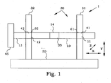
FIG. 1 is a schematic illustration of a sliding bearing in a micromotor; -
FIG. 2 is a schematic illustration of the displacement acceptance for an embodiment of the present invention; -
Fig. 3A illustrates a cross-sectional view of a first rail contacting portion not being part of the present invention; -
FIGS. 3B-G are schematic embodiments of a first rail contacting portion according to the present invention; -
FIGS. 4A-E are schematic embodiments of a second rail contacting portion according to the present invention; -
FIG. 5 is an elevation view of a preferred embodiment of an electromechanical motor according to the present invention with cover and spring removed; -
FIG. 6 is an explosion view of the embodiment ofFig. 5 ; -
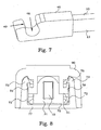
FIG. 7 is a detail illustration of a connection piece of the embodiment ofFig. 5 ; and -
FIG. 8 is a cross-sectional view of the embodiment ofFig. 5 , illustrating a flexible printed circuit board being fixed against support pillars. - In the present disclosure, a motor based on piezoelectric drive elements is used as an example during the detailed description. However, anyone skilled in the art realizes that the same principles are applicable also to other electromechanical driving principles as well. Likewise, even if the exemplary motor of the present disclosure is a linear motor, similar principles are also applicable to rotating motors. The moving part of the motor, i.e. in the linear case the shuttle, is in the present disclosure denoted by "rail". This term "rail" should not imply any unreasonable limitations, but should instead be understood as "the body to be moved", regardless of the actual shape.
-
Fig. 1 illustrates a simplified illustration of alinear motor 1, comprising arail 10, relative to which adriving element 20 applies a driving force in a direction X. Direction X is inFig. 1 illustrated as the direction left-right and coincides with a main extension of therail 10. A direction Z is defined as a direction substantially perpendicular to the surface of therail 10 on which the drivingelement 20 operates. Direction Z is therefore transverse to the main extension X of saidrail 10. A direction Y is finally defined as substantially perpendicular to both directions X and Z, i.e. the height dimension inFig. 1 . The direction Y is thus transverse to both the main extension X of the rail and transverse to the direction Z. - The
rail 10 is mounted by a bearing, generally denoted by 30, comprising a firstrail contacting portion 31 and a secondrail contacting portion 32. Therail 10 is typically supported by a mechanical static or sliding contact withinner surfaces rail contacting portion 31 and the secondrail contacting portion 32, respectively. Afront end 13 of therail 10 is attached to an externalmovable part 45, to which the motion of the motor is going to be transferred. Thebearing 30 is attached to ahousing 50 of themotor 1. Also the drivingelement 20 is by its rear end directly or indirectly attached to the housing 50 (not shown). - The motor output force will be reduced when the friction between the bearing 30 and the
rail 10 is increased. Therail contacting portions inner surfaces rail 10 when all components are in their ideal position. The manufacturing tolerances of the respective parts are included in this play. The play should be large enough to avoid undesired friction between the inner surfaces and the rail. In most motors the play can, however, not be made too large since the operation of the drivingelement 20 might be affected negatively and therefore other solutions than simply increasing the play has to be found. The present invention presents several embodiments of a solution to reduce undesired friction effects. -
Fig. 2 illustrates an embodiment of a motor according to the present invention. As before, thebearing 30 comprises the firstrail contacting portion 31 and the secondrail contacting portion 32. Therail 10 is typically supported by a mechanical static or sliding contact withinner surfaces rail contacting portion 31 and the secondrail contacting portion 32, respectively. Theinner surfaces hollow volumes -
Fig. 2 shows a situation, where the manufacturing of themotor housing 50 has resulted in a slight tilting of therail contacting portions rail 10 and therail contacting portions inner surfaces rail 10 with respect to therail contacting portions rail 10 will come into contact with therail contacting portions rail 10. This causes a drastic increase in the friction. - If the play in the
rail contacting portions rail 10 typically results in a deteriorated operation, since the ideal operations conditions at the drivingportion 14 are disturbed. If the displacement would be directed in the Z direction, the influence on the driving conditions would probably be even worse, since displacements are occurring in the contact force direction, which typically is more sensitive. - Moreover, if the external
movable part 45 imposes a rotation R of therail 10 around an axis parallel to the main extension X of therail 10, also this will probably cause difficult operational disturbances, in particular when a resonant piezoelectric drive element is used. The alignment of thedrive element 20 of a piezoelectric motor, e.g. according to the principles discussed in the U.S. patent application No.US 2006/175932 A1 is essential for proper operation. Here it is shown how smaller alignment errors can be compensated for by self-aligning configurations. Even if a partially self-aligning drive element support is used, excessive displacement or rotation will anyway result in deteriorated operation. - In cases where the
rail 10 is weaker, consists of assembled parts etc., also therail 10 may be subject of deformation. The result will eventually be the same, since it is the relative conditions between therail contacting portions rail 10 that are of importance. - The first
rail contacting portion 31 is arranged for providing a rigid support to therail 10 at the position of the firstrail contacting portion 31. In particular, theinner surface 61 is shaped for obstructing displacements of therail 10 in the Z direction. Preferably, theinner surface 61 is also shaped for obstructing rotation of therail 10 around an axis parallel to the main extension X of therail 10 that goes beyond what an appropriate play allows. In other words, theinner surface 61 is shaped for obstructing excessive displacements of therail 10 in the Z direction and preferably as well as for obstructing excessive rotation of therail 10 around an axis parallel to the main extension X of therail 10. Preferably, theinner surface 61 is further shaped also for obstructing displacements of therail 10 in the Y direction. Aportion 11 of therail 10 situated in thehollow volume 41 will thereby be kept in an essentially non-displaced position, i.e. within acceptable displacement tolerances for the piezoelectric drive element. - The second
rail contacting portion 32 could be equal to the firstrail contacting portion 31 but is in a preferred embodiment different from the firstrail contacting portion 31. The secondrail contacting portion 32 is then instead arranged for providing a rigid displacement support to the rail at the position of the secondrail contacting portion 32, while being flexible against tilting and rotation. Tilting of one of the rail contacting portions relative the other rail contacting portion will result in a rotation of theinner surface rail 10. There might be rotations around all three axes X, Y and Z. Theinner surfaces rail 10 in the Z direction. Theinner surface 62 is in contrast toinner surface 61 arranged for allowing a minor excessive rotation movement, i.e. relative rotation movements, larger than those allowed due to the designed mechanical play, between the rail and the secondrail contacting portion 32. In particular, at least one of a rotation of the secondrail contacting portion 32 around the axis parallel to the main extension X of saidrail 10, and a tilting of the secondrail contacting portion 32 is allowed (i.e. a relative rotation around an axis along the Y or Z direction). In preferred embodiments, all these movements are allowed. In further preferred embodiments, theinner surface 62 is arranged for obstructing displacements of therail 10 in the Y direction, while allowing a minor tilting of the secondrail contacting portion 32 in the Y direction (i.e. a relative rotation around an axis along the Z direction). - A
portion 12 of therail 10 situated in thehollow volume 42 will thereby be kept in position, while being allowed to rotate or tilt somewhat. Such rotation and/ or tilting will accommodate smaller manufacturing errors or deformations due to external forces on the motor housing, thereby reducing the risk for uncontrolled deformation or breakage of thebearing 30 and prohibiting or at least mitigating increased friction. - At the same time, the rigid support in the first
rail contacting portion 31 will reduce the effects of tilting and rotation at the drivingportion 14 of therail 10, thereby ensuring a reliable operation. This combination of rigidity and flexibility at different portions of therail 10 provides robustness to the entire arrangement. - When taking a predefined play into account, the second rail contacting portion is arranged for obstructing displacements of the rail in a first direction transverse to the main extension of the rail larger than the predefined play, while allowing at least a minor rotation of the rail relative to the second rail contacting portion in excess of what the predefined play allows.
- The actual shape of the
rail contacting portions bearing 30 can be designed in different ways.Figs. 3A illustrates one examples of a shapes usable for the firstrail contacting portion 31.Fig. 3A illustrates a cross-sectional view of a firstrail contacting portion 31. Theinner surface 61 presents in thisembodiment protruding portions 64 protruding into thehollow volume 41, coming into contact with therail 10. Thehollow volume 41 is in this embodiment a closed hollow volume, i.e. theinner surface 61 encircles the entirehollow volume 41. Therail 10 has in the present embodiment a rectangular cross-section, presenting two pairs of plane-parallel sides portions 64 provide apoint contact 63 at each of the four sides 15-18, which prevents displacements as well as rotations. -
Figs. 3B-G illustrates some examples of a shape usable for the firstrail contacting portion 31 according to the present invention. InFig. 3B , arail 10, having a rounded cross-sectional shape is illustrated. Therail 10 presents two plane-parallel sides inner surface 61 also here comprises protrudingportions 64, in this embodiment two at each side of therail 10. The protrudingportions 64 creates twopoint contacts 63 on eachside hollow volume 41, which does not provide restrictions in the Y direction. -
Fig. 3C illustrates a presently preferred embodiment of a firstrail contacting portion 31. The hatching is removed and only one reference figure of each number is shown in order to increase the figure readability. In this embodiment, therail 10 presents four plane sides 15-18. Theinner surface 61 comprises protrudingportions 64, but now with a flat top 65, which is in conformity with the rail sides 15-18. The flat top 65 thus provides aline contact 66 with therail 10, transverse to the main extension of therail 10. Theline contact 66 can also be viewed as a number of overlapping point contacts. The prevention of rotations and displacements in the Z and Y directions is very steady in the present embodiment. The protrudingportions 64 of the firstrail contacting portion 31 of the embodiment ofFig. 3C do not extend all the way along the rail sides 15-18. Instead,cavities 67 are provided at the corners of thehollow volume 41. Thesecavities 67 thus provide a space relative the corners of the rectangular cross section of therail 10, i.e. the rail edges.Such cavities 67 can easily accommodate irregularities at the rail edges, which may be present e.g. as a result of the manufacturing process, for example minor chips or bumps. Thecavities 67 allow for very sharp edges of therail 10 since even a small radius of the corners in a hollowrectangular volume 41 would result in increased friction. -
Fig. 3D illustrates a cross-sectional view of an embodiment of a firstrail contacting portion 31 taken along the axis of therail 10. Theinner surface 61 is here flat over thehollow volume 41, contacting thesurface rail 10 over essentially thewhole portion 11. Such an arrangement becomes very stable against tilting therail portion 11 within thehollow volume 41, since a two-dimensional area contacts 68 is created. Thearea contact 68 can also be viewed as a number of overlapping line contacts. However, there is a risk for jamming therail 10 in thehollow volume 41. -
Fig. 3E illustrates another embodiment, where the flat part of theinner surface 61 does not extend over theentire portion 11. Such an arrangement reduces the risk for jamming, however, the stability against tilting is reduced. In cases where tilting is not very severe, the extension of thearea contact 68 can be even further reduced. InFig. 3F , theinner surface 61 is vaulted in the X direction, i.e. along the main extension of saidrail 10. InFig. 3G , theinner surface 61 is inclined in the X direction, presenting a point contact or line contact at an edge of the firstrail contacting portion 31. - By designing the first
rail contacting portion 31 with an angle at the contact point, the firstrail contacting portion 31 can additionally be used to remove any impurities from the surface of therail 10. Such impurities may e.g. comprise wear debris from the driving element or rail during the operation. Excess material present on the surface of the rail may change the friction conditions considerably. Depending on the specific situation, both increased and decreased friction coefficients may be the result. -
Figs. 4A-E illustrate some examples of shapes usable for the secondrail contacting portion 32, i.e. the part of the bearing that preferably is closest to the part where any external devices are attached. InFig. 4A , arail 10 in the same shape as inFig. 3B is illustrated. Theinner surface 62presents protruding portions 43, contacting therail 10 atpoint contacts 63. Thehollow volume 42 is here open and the displacement in the Y direction is only prohibited by a support of one of the protrudingportions 43. Therail portion 12 in thehollow volume 42 is here allowed to rotate somewhat around the rail axis. - In
Fig. 4B , in a presently preferred embodiment, the protrudingportions 43 are rounded off, which provides a more gentle interaction with the secondrail contacting portion 32. Also here, a minor rotation around the rail axis is permitted. Furthermore, the secondrail contacting portion 32 encircles in this embodiment thehollow volume 42, and prevents therail 10 from all displacements also in the Y direction. -
Fig. 4C illustrates the secondrail contacting portion 32 in another cross-sectional view. One can here see that in order to allow for tilting the rail contacting portion somewhat, the extension of thecontact point 63 along therail 10 is kept small. Theinner surface 62 is here vaulted in the X direction, i.e. along the main extension of saidrail 10. InFig. 4D theinner surface 62 is inclined in the X direction, presenting a point contact at an edge of the secondrail contacting portion 32. InFig. 4E , the inner surface presents an angle shape in the X-direction. This can also help in cleaning the rail from worn material during the driving operation. - An embodiment of a motor according to the present invention is illustrated in an elevation view in
Fig. 5 , with a spring and cover removed. The scale is much enlarged in order to show the details. The entire motor assembly is in reality just about 15 mm long. Therail 10 is provided with astopper 47 at the rear end, prohibiting the rail to be pushed out from the motor. In thefront end 13, aconnection piece 46 is attached, which will be discussed more in detail below. - A
housing 75 is based on an injection molded piece, comprising the firstrail contacting portion 31 and the secondrail contacting portion 32. The housing of the present embodiment also comprises protrudingsupport pillars 73 at each corner of themotor 1. The drivingelements 20 compriseactive volumes 23 of piezoelectric material, i.e. the electromechanically active material, which interacts with therail 10 viapads 21. The drivingelements 20 are in this embodiment smaller than 1 centimeter. Theactive volumes 23 of the drivingelements 20 are attached to a flexible printedcircuit board 70 at a respective foldedportion 72. The foldedportions 72 also present pivot supports 71, on which the spring (not shown) will apply it force. The flexible printedcircuit board 70 is supported by the upper surface of the bottom part of thehousing 75 and by thesupport pillars 73. The flexible printedcircuit board 70 will be clamped by the cover (not shown), which will be discussed more in detail below. The electrical connections to the drivingelements 20 are made through the flexible printedcircuit board 70 and are extracted from the center of the motor by alongitudinal portion 74. -
Fig. 6 illustrates an exploded view of themotor 1 ofFig. 5 , now also including acover 90 and aspring 85. InFig. 6 , the folded shape of the flexible printedcircuit board 70 with the drivingelements 20 attached is easily distinguished. Likewise, the injection moldedhousing 75 is easily seen. The figure also comprises abase plate 80, which is to be fastened on a support of the device in which the motor should be operating, by utilizing the screw towers 81. Snap locks 82 are then easily inserted into corresponding openings in the housing, and themotor 1 is easily snapped onto thebase plate 80. - The
base plate 80 and the screw towers 81 are manufactured to be relatively pliant. The screw towers 81 are furthermore positioned on a minor elevation. Such arrangement allows the base plate to be fastened against a rough surface without causing excessive deformation of the motor housing and bearings. Such excessive deformation would influence the operational conditions of the motor. - The design of the
motor 1 is a mixture of modular thinking and integrated manufacturing. The flexible printedcircuit board 70 with the drivingelements 20 is manufactured in one piece, using standard techniques within electric circuit manufacturing. This facilitates the precision positioning of the different parts of the driving elements, thereby ensuring controlled driving properties. Likewise, thehousing 75, including thebearing 30, i.e. essentially the firstrail contacting portion 31 and the secondrail contacting portion 32, is manufactured in one piece. This ensures a high precision of relative positions and dimensions of the different portions of thehousing 75. Most dimensions that are tolerance critical are manufactured in this manner. - However, the separated parts shown in
Fig. 6 constitute in another view a base for a modular manufacturing thinking. A number of modules are prepared to fit together and are easily mounted by a few simple operations. Moreover, the different modules can easily be exchanged to other modules for particular purposes. In such a way, for instance driving elements having different driving properties can be provided with a separate flexible printed circuit board and anyway be combined with the other modules. Likewise, if additional features are required, e.g. if a sensor should be used to detect the position of the rail, thebase plate 80 can easily be exchanged for a base plate prepared to hold a sensor at the right position. -
Fig. 7 shows a detail illustration of thefront end 13 of the rail, together with an embodiment of aconnection piece 46. Theconnection piece 46 is prepared to hold a rod-shaped piece. Theconnection piece 46 therefore presents asurface 49 defining ahollow volume 48. Thehollow volume 48 has a main radius corresponding to the radius of the rod-shaped piece to attach. However, thesurface 49 is also curved in the transversal direction, thus giving a smallest radius of thehollow volume 48 at the middle and slightly larger radius at the sides of theconnection piece 46. This design resembles to some extent the design of the bearing discussed above, and is provided by similar reasons, i.e. to allow for small amounts of position or directional errors during mounting or operation, in this particular embodiment a directional error of ±3 degrees. Undesired friction effects in the bearing 30 from application related forces and torques are thus reduced. - The mounting of the driving elements relative to the rail also has preferably to involve a certain degree of flexibility. The contact angle between driving element and rail is often critical for a controlled and repeatable operation. Minor faults in dimensions or mounting errors should preferably be correctable by using a certain degree of movement freedom of the driving element. The driving element in the present embodiment is mounted on a flexible printed circuit board. In
Fig. 8 , the mounting of the flexible printed circuit board is illustrated. This mounting principle provides flexibility to the driving element positioning. As described before, the driving elements are mounted on the surface of foldedportions 72 of the flexible printedcircuit board 70. The flexible printedcircuit board 70 has the property of being flexible in directions transverse to the board plane and rotations around the X-direction, but relatively stiff concerning forces directed in the plane of the board. In particular in such small devices as the motors described here, the stiffness of the flexible printedcircuit board 70 becomes very large indeed compared to expected forces on the different portions. - For positioning reasons of the motor, it is required that motions of the driving element parallel to the rail only are due to electromechanical actions. Any displacement flexibility of the driving elements in this direction is therefore unwanted. To this end the folded
portions 72 of the flexible printedcircuit board 70 are positioned parallel to therail 10. FromFig. 8 it is easily seen that the foldedportions 72 are supported against thesupport pillars 73 of thehousing 75. A protrudingedge 76 of thesupport pillars 73 prohibits the foldedportions 72 to move upwards and by utilizing the rigidity of the flexible printedcircuit board 70, the flexible printedcircuit board 70 is thereby pressed against a bottom part of thehousing 75. Since the arrangement is symmetrical, both driving elements are thereby fixated in height, i.e. in the Y direction. The fixation in the X direction can be provided by letting the flexible printedcircuit board 70 support againsthousing 75 or cover portions (not shown). The driving elements are thus almost immovable in both the X and Y directions. - In contrary, as described further above, the driving elements are often required to be somewhat flexible to displacements in the Z direction, as well as to minor rotations around the X axis, in order to compensate for e.g. mounting induced errors. This is also provided by the flexible printed
circuit board 70. At the front end of the flexible printedcircuit board 70, i.e. at the end closest to the secondrail contacting portion 32, there is a small space provided inside of the flexible printedcircuit board 70 when mounted against thesupport pillars 73. The flexible printedcircuit board 70 may therefore bend a smaller distance away from thesupport pillars 73. The spring 85 (Fig. 6 ) pressing the driving element against therail 10 is mounted in such a way that a self-centering action is provided to the driving element. Any misalignment of therail 10 can therefore be compensated by a minor bending or rotation of the flexible printed circuit board. The flexible printed circuit board can also be provided with a reduced width between thepillars 73 and the drive elements to increase the flexibility. - However, in order to have some sort of control of the situation, the rear end of the folded
portions 72 of the flexible printedcircuit board 70 is fixed against thesupport pillars 73. Upon mounting, the flexible printed circuit board is simply pressed into a well determined volume, defined by thesupport pillars 73, the protruding edges 76 and the housing bottom. The shape of thehousing 75 will thereby insure that the flexible printed circuit board will be correctly positioned. The basic alignment in the Z direction and rotation around the X axis of the drive elements relative to the drive rail is controlled by thesupport pillars 73. - The
cover 90 is provided withtabs 78 which can be forced between thesupport pillars 73 and which will snap against the foldedportions 72 when coming below the protrudingedge 76. Thecover 90 is close to thesupport pillars 73 and stiff enough to prohibit bending of thesupport pillars 73 due to forces from thetabs 78. The foldedportions 72 are thereby clamped against thesupport pillars 73, prohibiting any motion at all of the foldedportions 72. The foldedportions 72 are thus kept in position primarily by the protruding edges 76 and then locked by thetabs 78. - The flexibility of the flexible printed
circuit board 70 should be adapted to the actual application. A deflection of the flexible printedcircuit board 70 will apply forces on the driving elements that are not completely controllable. It has been found that reliable operation can be achieved if the maximum allowed deflection of the flexible printedcircuit board 70 could be achieved by a force less than 20% of the spring force by which the driving element is pressed against the rail. Preferably, the force should be less than 10% or even lower. - As mentioned above, in connection with
Figs. 5 and6 , the housing is preferably manufactured as one integral piece. A presently preferred method is to utilize injection molding. The material used in the bearing can be selected in different ways. The bearing of the embodiment ofFigs. 5 to 8 is manufactured in a polymer material. Preferably, the material is a composite material also comprising e.g. glass fibers or other structural enforcing materials. The polymer material can also be provided by friction reducing microparticles e.g. teflon, thereby decreasing surface friction. However, also materials such as softer metals, e.g. aluminium can be possible to use for the housing. - The approach for solving bearing problems, i.e. using dry, sliding bearings without any lubrication, is to a large part connected to the small size of the motors. Gravitational forces caused by e.g. the rail will be almost negligible and the motor can be mounted in any direction without any consideration of gravity. Furthermore, the small size puts corresponding requirements on tolerances. The tolerances then become so strict that conventional approaches to bearing etc. can not be applied directly if the manufacturing costs have to be kept low.
- The embodiment of the motor presented in the
Figs. 5 to 8 can in certain applications be provided with additional positioning sensing functionality. A presently preferred way to achieve this is to provide the rail with a surface, having a variable light reflection along the X direction. A light source generates a light signal which is transmitted against a reflection region on the variable light reflection surface. Light reflected from the variable light reflection surface is detected by a light detector and the intensity of the reflected light is measured in comparison with the light intensity emitted by the source. Since the location of the reflection region at the rail is connected to the reflected amount of light, a position of the rail can be determined from the detected reflected light signal. - The embodiments described above are to be understood as a few illustrative examples of the present invention. It will be understood by those skilled in the art that various modifications, combinations and changes may be made to the embodiments without departing from the scope of the present invention. In particular, different part solutions in the different embodiments can be combined in other configurations, where technically possible. The scope of the present invention is, however, defined by the appended claims.
Claims (27)
- Electromechanical motor (1), comprising:a rail (10); andbearing (30) for said rail (10);said bearing (30) being a sliding bearing having a first rail contacting portion (31) and a second rail contacting portion (32);driving member (20);said first rail contacting, portion (31) being in contact with said rail (10) and having an inner surface (61) obstructing displacements of said rail (10) in a first direction (Z, Y) transverse to a main extension of said rail (10);said second rail contacting portion (32) having an inner surface (62) obstructing displacements of said rail (10) in said first direction transverse (Z, Y) to said main extension of said rail (10), while allowing in contrast to the inner surface (61) of said first rail contacting portion (31) at least a minor rotation of said second rail contacting portion (32) relative to said rail (10) around a first axis (Z, Y) transverse to said main extension of said rail (10),
characterised in thatsaid rail (10) is to be moved;said driving member (20 being arranged to impose a mechanical driving force on said rail (10);said rail (10) has a cross-section with at least one pair of plane-parallel sides (15-18); andsaid first rail contacting portion (31) having one of:at least two point contacts;a line contact; andan area contact,-with each of the plane-parallel sides (15-18). - Electromechanical motor according to claim 1, characterised in that said first rail contacting portion (31) is arranged for obstructing rotation of said rail (10) around an axis (X) parallel to said main extension of said rail (10).
- Electromechanical motor according to claim 1 or 2, characterised in that said minor rotation comprises a relative rotation between said rail (10) and said second rail contacting portion (32) around said axis (X) parallel to said main extension of said rail (10) and a relative rotation between said rail (10) and said second rail contacting portion (32) around said first axis (Z, Y) transverse to said main extension of said rail (10).
- Electromechanical motor according to any of the claims 1 to 3, characterised in that said first rail contacting portion (31) is further arranged for obstructing displacements of said rail (10) in a second direction (Y, Z) transverse to said main extension of said rail (10) and transverse to said first direction (Z, Y), and said second rail contacting portion (32) is further arranged for allowing at least a minor relative rotation between said rail (10) and said second rail contacting portion (32) around a second axis (Y, Z) transverse to said main extension of said rail (10).
- Electromechanical motor according to any of the claims 1 to 4, characterised in that said rail (10) being positioned through a first hollow volume (41) of said first rail contacting portion (31) and a second hollow volume (42) of said second rail contacting portion (32).
- Electromechanical motor according to claim 5, characterised in that said first hollow volume (41) is a first hole and said second hollow volume (42) is a second hole, whereby said first rail contacting portion (31) encircles said first hollow volume (41) and said second rail contacting portion (32) encircles said second hollow volume (42).
- Electromechanical motor according to any of the claims 1 to 6, characterised in that said at least two point contacts are parts of at least a line contact (66, 68) transverse to said main extension of said rail (10).
- Electromechanical motor according to claim 7, characterised in that said at least a line contact is a part of an area (68) contact parallel to said plane-parallel sides (15-18).
- Electromechanical motor according to any of the claims 1 to 8, characterised in that said second rail contacting portion (32) having at least one point contact (63) with each of the plane-parallel sides (15-18).
- Electromechanical motor according to any of the claims 1 to 9, characterised in that the inner surface (61, 62) of at least one of said first rail contacting portion (31) defining said first hollow volume (41) and said second rail contacting portion (32) defining said second hollow volume (42), being inclined in a direction along said main extension of said rail (10).
- Electromechanical motor according to claim 10, characterised in that said inner surface (61, 62) of at least one of said first rail contacting portion (31) defining said first hollow volume (41) and said second rail contacting portion (32) defining said second hollow volume (42), being vaulted in a direction along said main extension of said rail (10).
- Electromechanical motor according to claim 10 or 11, characterised in that a contact point between said inner surface (61, 62) and said rail (10) is situated at an edge of said first rail contacting portion (31) or said second rail contacting portion (32).
- Electromechanical motor according to any of the claims 1 to 12, characterised in that said rail (10) has a substantially rectangular cross section, whereby said first rail contacting portion (31) and said second rail contacting portion (32) have contact points with all plane-parallel surfaces (15-18) of said rectangular cross section.
- Electromechanical motor according to claim 13, characterised in that at least one of said first rail contacting portion (31) and said second rail contacting portion (32) is arranged with a space (67) relative corners of said rectangular cross section.
- Electromechanical motor according to any of the claims 1 to 14, characterised in that said bearing (30) is a dry, non-lubricated, sliding bearing.
- Electromechanical motor according to any of the claims 1 to 15, characterised in that said driving member (20) is arranged to impose a mechanical driving force on said rail (10) at a position between said first rail contacting portion (31) and said second rail contacting portion (32).
- Electromechanical motor according to any of the claims 1 to 16, characterised in that a motion of said driving member (20) being caused by shape changes of volumes (23) of electromechanically active material.
- Electromechanical motor according to claim 17, characterised in that said driving member (20) being smaller than 1 centimetre.
- Electromechanical motor according to any of the claims 1 to 18, characterised in that said first rail contacting portion (31) and said second rail contacting portion (32) are formed as one injection-moulded piece.
- Electromechanical motor according to any of the claims 1 to 19, characterised in that said driving member (20) comprises two driving elements arranged to interact with a respective plane-parallel side (15-18) of said rail (10), said driving elements being connected to a flexible printed circuit board (70), said flexible printed circuit board (70) being fastened against a housing (75) of said electromechanical motor (1) prohibiting motion relative said housing (75) along said main extension of said rail (10).
- Electromechanical motor according to claim 20, characterised in that said flexible printed circuit board (70) is fixed to said housing (75) at one side of said driving elements in said direction (X) of said main extension of said rail (10), while said flexible printed circuit board (70) is arranged with a minor displacement possibility in a direction (Z) perpendicular to said respective plane-parallel side (15-18) of said rail (10) at an opposite side of said driving elements in said direction (X) of said main extension of said rail (10).
- Electromechanical motor according to claim 20 or 21, characterised in that said flexible printed circuit board (70) is fixed to said housing (75) at one side of said driving elements in said direction (X) of said main extension of said rail (10), while said flexible printed circuit board (70) is arranged with a minor rotation possibility of said drive elements relative said rail (10).
- Electromechanical motor according to claim 21 or 22, characterised in that said minor displacement and/or rotation possibility allows for a displacement of said flexible printed circuit board (70) caused by a force that is 20 percent of a force by which said driving elements are pressed against said rail (10).
- Electromechanical motor according to any of the claims 21 to 23, characterised in that said flexible printed circuit board (70) is fixed to said housing (75) by snap clamping between a cover portion (90) and said housing (75).
- Electromechanical motor according to any of the claims 20 to 24, characterised in that said housing (75) is formed in one piece together with said first rail contacting portion (31) and said second rail contacting portion (32).
- Electromechanical motor according to any of the claims 20 to 25, characterised in that said housing (75) has a shape defining a volume in which said flexible printed circuit board (70) is to be mounted, whereby said flexible printed circuit board (70) is positioned in a well-defined position by said volume.
- Electromechanical motor according to any of the claims 1 to 26, characterised by further comprising a connection piece (46) attached to a front end (13) of said rail (10) for connection of a rod-shaped piece to be attached, said connection piece (46) presenting a surface defining a hollow volume, said hollow volume having a main radius (48) corresponding to a radius of the rod-shaped piece, said surface being further curved (49) in a direction along said rod-shaped piece, whereby minor directional errors are allowed.
Applications Claiming Priority (2)
| Application Number | Priority Date | Filing Date | Title |
|---|---|---|---|
| US11/262,797 US7348710B2 (en) | 2005-11-01 | 2005-11-01 | Robust electromechanical motor |
| PCT/EP2006/067207 WO2007051689A1 (en) | 2005-11-01 | 2006-10-09 | Robust electromechanical motor |
Publications (2)
| Publication Number | Publication Date |
|---|---|
| EP1943722A1 EP1943722A1 (en) | 2008-07-16 |
| EP1943722B1 true EP1943722B1 (en) | 2010-12-22 |
Family
ID=37763791
Family Applications (1)
| Application Number | Title | Priority Date | Filing Date |
|---|---|---|---|
| EP06807093A Active EP1943722B1 (en) | 2005-11-01 | 2006-10-09 | Robust electromechanical motor |
Country Status (7)
| Country | Link |
|---|---|
| US (1) | US7348710B2 (en) |
| EP (1) | EP1943722B1 (en) |
| JP (1) | JP5367373B2 (en) |
| KR (1) | KR101353734B1 (en) |
| AT (1) | ATE492911T1 (en) |
| DE (1) | DE602006019121D1 (en) |
| WO (1) | WO2007051689A1 (en) |
Cited By (1)
| Publication number | Priority date | Publication date | Assignee | Title |
|---|---|---|---|---|
| DE102013204026A1 (en) * | 2013-03-08 | 2014-09-11 | Physik Instrumente (Pi) Gmbh & Co. Kg | Actuator arrangement for an ultrasonic motor |
Families Citing this family (8)
| Publication number | Priority date | Publication date | Assignee | Title |
|---|---|---|---|---|
| JP4982795B2 (en) * | 2007-06-07 | 2012-07-25 | コニカミノルタアドバンストレイヤー株式会社 | DRIVE DEVICE AND DRIVE DEVICE UNIT |
| DE102008016684B4 (en) * | 2008-04-01 | 2015-10-08 | Minebea Co., Ltd. | Electromechanical motor |
| JP5254286B2 (en) * | 2010-08-17 | 2013-08-07 | アイシン・エーアイ株式会社 | Support structure for transmission fork shaft |
| USD659639S1 (en) * | 2010-10-23 | 2012-05-15 | NanoTechnology System Corporation (NATSYCO) | Platform connector |
| USD639737S1 (en) * | 2010-10-23 | 2011-06-14 | NanoTechnology System Corporation (NATSYCO) | Piezomotor connector |
| CN103427704B (en) * | 2013-07-31 | 2016-01-13 | 南京航空航天大学 | Biped drives piezoelectric linear motor and electric excitation mode |
| JP6520312B2 (en) * | 2015-03-31 | 2019-05-29 | ブラザー工業株式会社 | Ink jet recording device |
| CN113544966A (en) | 2019-02-22 | 2021-10-22 | 高压马达乌普萨拉有限公司 | Electromechanical motor and tunable filter including electromechanical motor |
Family Cites Families (25)
| Publication number | Priority date | Publication date | Assignee | Title |
|---|---|---|---|---|
| JPS55101622U (en) * | 1979-01-08 | 1980-07-15 | ||
| JPS5973622A (en) * | 1982-10-19 | 1984-04-25 | Nobuyuki Tsuboi | Slide bearing |
| JPS6162370A (en) * | 1984-08-31 | 1986-03-31 | Tokyo Juki Ind Co Ltd | Piezoelectric motor |
| JPH03212177A (en) * | 1990-01-11 | 1991-09-17 | Brother Ind Ltd | Ultrasonic transducer and method for manufacturing the ultrasonic transducer |
| JPH0595816A (en) * | 1991-10-04 | 1993-04-20 | Toshiba Corp | Bearing structure for electric toothbrush or the like |
| JP3107933B2 (en) * | 1992-12-03 | 2000-11-13 | キヤノン株式会社 | Vibration wave driving device and device provided with vibration wave driving device |
| JPH06276769A (en) * | 1993-03-16 | 1994-09-30 | Canon Inc | Vibrating-wave linear motor and printer |
| US5596241A (en) | 1993-01-18 | 1997-01-21 | Canon Kabushiki Kaisha | Vibration wave driven linear-motor or printer |
| JP3155109B2 (en) | 1993-01-22 | 2001-04-09 | キヤノン株式会社 | Vibration wave driving device and printer device |
| US5389845A (en) * | 1993-11-22 | 1995-02-14 | Technical Research Associates, Inc. | Linear actuator apparatus and method |
| JP3352260B2 (en) * | 1994-12-27 | 2002-12-03 | キヤノン株式会社 | Lens drive |
| US6218767B1 (en) | 1996-01-08 | 2001-04-17 | Canon Kabushiki Kaisha | Vibration device |
| JP3524248B2 (en) * | 1996-01-08 | 2004-05-10 | キヤノン株式会社 | Vibration device |
| JPH1146487A (en) * | 1997-07-28 | 1999-02-16 | Canon Inc | Vibration actuator |
| US6215605B1 (en) * | 1998-07-02 | 2001-04-10 | Minolta Co., Ltd. | Driving device |
| US6467669B1 (en) * | 1999-07-22 | 2002-10-22 | Kabushiki Kaisha Meiji Gomu Kasei | Pinch roller device |
| US6690101B2 (en) * | 2000-03-23 | 2004-02-10 | Elliptec Resonant Actuator Ag | Vibratory motors and methods of making and using same |
| JP4596610B2 (en) * | 2000-05-31 | 2010-12-08 | キヤノン株式会社 | Vibration wave drive |
| JP2002314156A (en) * | 2001-04-12 | 2002-10-25 | Denso Corp | Piezoelectric element |
| US6611080B2 (en) * | 2001-06-04 | 2003-08-26 | Nanyang Technological University | Linear piezoelectric motor with self locking means |
| JP2003079166A (en) * | 2001-08-31 | 2003-03-14 | Minolta Co Ltd | Moving mechanism |
| AU2002354358A1 (en) * | 2001-11-23 | 2003-06-10 | Ecicm B.V. | Method and devices for driving a body |
| JP2003161319A (en) * | 2001-11-27 | 2003-06-06 | Ndc Co Ltd | Linear guide plain bearing |
| US6747394B2 (en) | 2002-06-19 | 2004-06-08 | Piezomotor Uppsala Ab | Near-resonance electromechanical motor |
| FR2845440B1 (en) * | 2002-10-03 | 2006-03-31 | Sagem | DEVICE FOR CONTROLLING VALVES |
-
2005
- 2005-11-01 US US11/262,797 patent/US7348710B2/en not_active Expired - Lifetime
-
2006
- 2006-10-09 EP EP06807093A patent/EP1943722B1/en active Active
- 2006-10-09 KR KR1020087012905A patent/KR101353734B1/en not_active Expired - Fee Related
- 2006-10-09 JP JP2008538317A patent/JP5367373B2/en not_active Expired - Fee Related
- 2006-10-09 AT AT06807093T patent/ATE492911T1/en not_active IP Right Cessation
- 2006-10-09 WO PCT/EP2006/067207 patent/WO2007051689A1/en not_active Ceased
- 2006-10-09 DE DE602006019121T patent/DE602006019121D1/en active Active
Cited By (2)
| Publication number | Priority date | Publication date | Assignee | Title |
|---|---|---|---|---|
| DE102013204026A1 (en) * | 2013-03-08 | 2014-09-11 | Physik Instrumente (Pi) Gmbh & Co. Kg | Actuator arrangement for an ultrasonic motor |
| DE102013204026B4 (en) | 2013-03-08 | 2019-08-08 | Physik Instrumente (Pi) Gmbh & Co. Kg | Actuator arrangement for an ultrasonic motor |
Also Published As
| Publication number | Publication date |
|---|---|
| WO2007051689B1 (en) | 2007-08-02 |
| DE602006019121D1 (en) | 2011-02-03 |
| JP2009514501A (en) | 2009-04-02 |
| JP5367373B2 (en) | 2013-12-11 |
| ATE492911T1 (en) | 2011-01-15 |
| US20070096599A1 (en) | 2007-05-03 |
| KR101353734B1 (en) | 2014-01-21 |
| EP1943722A1 (en) | 2008-07-16 |
| KR20080074917A (en) | 2008-08-13 |
| WO2007051689A1 (en) | 2007-05-10 |
| US7348710B2 (en) | 2008-03-25 |
Similar Documents
| Publication | Publication Date | Title |
|---|---|---|
| US7973855B2 (en) | Image shake correction apparatus and method | |
| US7348710B2 (en) | Robust electromechanical motor | |
| KR101504048B1 (en) | Attachment mechanism | |
| US10247902B2 (en) | Motor and apparatus using the same | |
| JP5673649B2 (en) | Lens drive device | |
| CN102176644A (en) | Drive apparatus | |
| WO2010088932A1 (en) | Assembling procedure for a piezoelectric motor | |
| CN112799204B (en) | Lens driving device, camera device and electronic equipment | |
| US9991823B2 (en) | Assembly for an ultrasonic motor | |
| US8018125B2 (en) | Linear drive ultrasonic motor | |
| US11621654B2 (en) | Vibration-wave motor and apparatus using the same | |
| US20230393449A1 (en) | Optical-element driving device, camera module and camera-mounted device | |
| KR20240076699A (en) | Positioning device for positioning a movable element | |
| CN1812245B (en) | Ultrasonic driving apparatus | |
| KR102671955B1 (en) | Ultrasonic actuators and motors equipped with such ultrasonic actuators | |
| JP2015087648A (en) | Camera module and electronic equipment, and method of positioning imaging lens | |
| US20110037347A1 (en) | Linear drive ultrasonic motor | |
| US7732979B2 (en) | Linear drive ultrasonic motor | |
| US20060209427A1 (en) | Electrostatic actuator and image pickup apparatus using the same | |
| US20230029605A1 (en) | Lens driving device, camera module, and camera mount device | |
| JP4164144B2 (en) | Preloading method of piezoelectric element in fine movement stage device and fine movement stage device | |
| KR20220159993A (en) | Lens driving device, camera module and camera mounting device | |
| JP7545853B2 (en) | Nut Assembly and Drive Unit | |
| EP3734246B1 (en) | Multiaxial actuator comprising a load sensor | |
| CN117337542A (en) | Linear or rotary stages capable of movement in two dimensions |
Legal Events
| Date | Code | Title | Description |
|---|---|---|---|
| PUAI | Public reference made under article 153(3) epc to a published international application that has entered the european phase |
Free format text: ORIGINAL CODE: 0009012 |
|
| 17P | Request for examination filed |
Effective date: 20080325 |
|
| AK | Designated contracting states |
Kind code of ref document: A1 Designated state(s): AT BE BG CH CY CZ DE DK EE ES FI FR GB GR HU IE IS IT LI LT LU LV MC NL PL PT RO SE SI SK TR |
|
| RAP1 | Party data changed (applicant data changed or rights of an application transferred) |
Owner name: PIEZOMOTOR UPPSALA AB |
|
| RAP1 | Party data changed (applicant data changed or rights of an application transferred) |
Owner name: PIEZOMOTOR UPPSALA AKTIEBOLAG |
|
| 17Q | First examination report despatched |
Effective date: 20100217 |
|
| GRAP | Despatch of communication of intention to grant a patent |
Free format text: ORIGINAL CODE: EPIDOSNIGR1 |
|
| RIC1 | Information provided on ipc code assigned before grant |
Ipc: H01L 41/09 20060101AFI20100707BHEP Ipc: H02N 2/04 20060101ALI20100707BHEP |
|
| DAX | Request for extension of the european patent (deleted) | ||
| GRAS | Grant fee paid |
Free format text: ORIGINAL CODE: EPIDOSNIGR3 |
|
| GRAA | (expected) grant |
Free format text: ORIGINAL CODE: 0009210 |
|
| AK | Designated contracting states |
Kind code of ref document: B1 Designated state(s): AT BE BG CH CY CZ DE DK EE ES FI FR GB GR HU IE IS IT LI LT LU LV MC NL PL PT RO SE SI SK TR |
|
| REG | Reference to a national code |
Ref country code: GB Ref legal event code: FG4D |
|
| REG | Reference to a national code |
Ref country code: CH Ref legal event code: EP |
|
| REG | Reference to a national code |
Ref country code: IE Ref legal event code: FG4D |
|
| REF | Corresponds to: |
Ref document number: 602006019121 Country of ref document: DE Date of ref document: 20110203 Kind code of ref document: P |
|
| REG | Reference to a national code |
Ref country code: DE Ref legal event code: R096 Ref document number: 602006019121 Country of ref document: DE Effective date: 20110203 |
|
| REG | Reference to a national code |
Ref country code: NL Ref legal event code: VDEP Effective date: 20101222 |
|
| PG25 | Lapsed in a contracting state [announced via postgrant information from national office to epo] |
Ref country code: LT Free format text: LAPSE BECAUSE OF FAILURE TO SUBMIT A TRANSLATION OF THE DESCRIPTION OR TO PAY THE FEE WITHIN THE PRESCRIBED TIME-LIMIT Effective date: 20101222 |
|
| LTIE | Lt: invalidation of european patent or patent extension |
Effective date: 20101222 |
|
| PG25 | Lapsed in a contracting state [announced via postgrant information from national office to epo] |
Ref country code: AT Free format text: LAPSE BECAUSE OF FAILURE TO SUBMIT A TRANSLATION OF THE DESCRIPTION OR TO PAY THE FEE WITHIN THE PRESCRIBED TIME-LIMIT Effective date: 20101222 Ref country code: LV Free format text: LAPSE BECAUSE OF FAILURE TO SUBMIT A TRANSLATION OF THE DESCRIPTION OR TO PAY THE FEE WITHIN THE PRESCRIBED TIME-LIMIT Effective date: 20101222 Ref country code: SI Free format text: LAPSE BECAUSE OF FAILURE TO SUBMIT A TRANSLATION OF THE DESCRIPTION OR TO PAY THE FEE WITHIN THE PRESCRIBED TIME-LIMIT Effective date: 20101222 Ref country code: FI Free format text: LAPSE BECAUSE OF FAILURE TO SUBMIT A TRANSLATION OF THE DESCRIPTION OR TO PAY THE FEE WITHIN THE PRESCRIBED TIME-LIMIT Effective date: 20101222 Ref country code: BG Free format text: LAPSE BECAUSE OF FAILURE TO SUBMIT A TRANSLATION OF THE DESCRIPTION OR TO PAY THE FEE WITHIN THE PRESCRIBED TIME-LIMIT Effective date: 20110322 Ref country code: CY Free format text: LAPSE BECAUSE OF FAILURE TO SUBMIT A TRANSLATION OF THE DESCRIPTION OR TO PAY THE FEE WITHIN THE PRESCRIBED TIME-LIMIT Effective date: 20101222 Ref country code: SE Free format text: LAPSE BECAUSE OF FAILURE TO SUBMIT A TRANSLATION OF THE DESCRIPTION OR TO PAY THE FEE WITHIN THE PRESCRIBED TIME-LIMIT Effective date: 20101222 |
|
| PG25 | Lapsed in a contracting state [announced via postgrant information from national office to epo] |
Ref country code: PT Free format text: LAPSE BECAUSE OF FAILURE TO SUBMIT A TRANSLATION OF THE DESCRIPTION OR TO PAY THE FEE WITHIN THE PRESCRIBED TIME-LIMIT Effective date: 20110422 Ref country code: CZ Free format text: LAPSE BECAUSE OF FAILURE TO SUBMIT A TRANSLATION OF THE DESCRIPTION OR TO PAY THE FEE WITHIN THE PRESCRIBED TIME-LIMIT Effective date: 20101222 Ref country code: BE Free format text: LAPSE BECAUSE OF FAILURE TO SUBMIT A TRANSLATION OF THE DESCRIPTION OR TO PAY THE FEE WITHIN THE PRESCRIBED TIME-LIMIT Effective date: 20101222 Ref country code: ES Free format text: LAPSE BECAUSE OF FAILURE TO SUBMIT A TRANSLATION OF THE DESCRIPTION OR TO PAY THE FEE WITHIN THE PRESCRIBED TIME-LIMIT Effective date: 20110402 Ref country code: GR Free format text: LAPSE BECAUSE OF FAILURE TO SUBMIT A TRANSLATION OF THE DESCRIPTION OR TO PAY THE FEE WITHIN THE PRESCRIBED TIME-LIMIT Effective date: 20110323 Ref country code: EE Free format text: LAPSE BECAUSE OF FAILURE TO SUBMIT A TRANSLATION OF THE DESCRIPTION OR TO PAY THE FEE WITHIN THE PRESCRIBED TIME-LIMIT Effective date: 20101222 Ref country code: IS Free format text: LAPSE BECAUSE OF FAILURE TO SUBMIT A TRANSLATION OF THE DESCRIPTION OR TO PAY THE FEE WITHIN THE PRESCRIBED TIME-LIMIT Effective date: 20110422 |
|
| PG25 | Lapsed in a contracting state [announced via postgrant information from national office to epo] |
Ref country code: NL Free format text: LAPSE BECAUSE OF FAILURE TO SUBMIT A TRANSLATION OF THE DESCRIPTION OR TO PAY THE FEE WITHIN THE PRESCRIBED TIME-LIMIT Effective date: 20101222 Ref country code: PL Free format text: LAPSE BECAUSE OF FAILURE TO SUBMIT A TRANSLATION OF THE DESCRIPTION OR TO PAY THE FEE WITHIN THE PRESCRIBED TIME-LIMIT Effective date: 20101222 Ref country code: RO Free format text: LAPSE BECAUSE OF FAILURE TO SUBMIT A TRANSLATION OF THE DESCRIPTION OR TO PAY THE FEE WITHIN THE PRESCRIBED TIME-LIMIT Effective date: 20101222 Ref country code: SK Free format text: LAPSE BECAUSE OF FAILURE TO SUBMIT A TRANSLATION OF THE DESCRIPTION OR TO PAY THE FEE WITHIN THE PRESCRIBED TIME-LIMIT Effective date: 20101222 |
|
| PLBE | No opposition filed within time limit |
Free format text: ORIGINAL CODE: 0009261 |
|
| STAA | Information on the status of an ep patent application or granted ep patent |
Free format text: STATUS: NO OPPOSITION FILED WITHIN TIME LIMIT |
|
| PG25 | Lapsed in a contracting state [announced via postgrant information from national office to epo] |
Ref country code: DK Free format text: LAPSE BECAUSE OF FAILURE TO SUBMIT A TRANSLATION OF THE DESCRIPTION OR TO PAY THE FEE WITHIN THE PRESCRIBED TIME-LIMIT Effective date: 20101222 |
|
| 26N | No opposition filed |
Effective date: 20110923 |
|
| PG25 | Lapsed in a contracting state [announced via postgrant information from national office to epo] |
Ref country code: IT Free format text: LAPSE BECAUSE OF FAILURE TO SUBMIT A TRANSLATION OF THE DESCRIPTION OR TO PAY THE FEE WITHIN THE PRESCRIBED TIME-LIMIT Effective date: 20101222 |
|
| REG | Reference to a national code |
Ref country code: DE Ref legal event code: R097 Ref document number: 602006019121 Country of ref document: DE Effective date: 20110923 |
|
| PG25 | Lapsed in a contracting state [announced via postgrant information from national office to epo] |
Ref country code: MC Free format text: LAPSE BECAUSE OF NON-PAYMENT OF DUE FEES Effective date: 20111031 |
|
| REG | Reference to a national code |
Ref country code: CH Ref legal event code: PL |
|
| GBPC | Gb: european patent ceased through non-payment of renewal fee |
Effective date: 20111009 |
|
| REG | Reference to a national code |
Ref country code: FR Ref legal event code: ST Effective date: 20120629 |
|
| PG25 | Lapsed in a contracting state [announced via postgrant information from national office to epo] |
Ref country code: CH Free format text: LAPSE BECAUSE OF NON-PAYMENT OF DUE FEES Effective date: 20111031 Ref country code: LI Free format text: LAPSE BECAUSE OF NON-PAYMENT OF DUE FEES Effective date: 20111031 |
|
| REG | Reference to a national code |
Ref country code: IE Ref legal event code: MM4A |
|
| PG25 | Lapsed in a contracting state [announced via postgrant information from national office to epo] |
Ref country code: GB Free format text: LAPSE BECAUSE OF NON-PAYMENT OF DUE FEES Effective date: 20111009 Ref country code: FR Free format text: LAPSE BECAUSE OF NON-PAYMENT OF DUE FEES Effective date: 20111102 |
|
| PG25 | Lapsed in a contracting state [announced via postgrant information from national office to epo] |
Ref country code: IE Free format text: LAPSE BECAUSE OF NON-PAYMENT OF DUE FEES Effective date: 20111009 |
|
| PG25 | Lapsed in a contracting state [announced via postgrant information from national office to epo] |
Ref country code: LU Free format text: LAPSE BECAUSE OF NON-PAYMENT OF DUE FEES Effective date: 20111009 |
|
| PG25 | Lapsed in a contracting state [announced via postgrant information from national office to epo] |
Ref country code: TR Free format text: LAPSE BECAUSE OF FAILURE TO SUBMIT A TRANSLATION OF THE DESCRIPTION OR TO PAY THE FEE WITHIN THE PRESCRIBED TIME-LIMIT Effective date: 20101222 |
|
| PG25 | Lapsed in a contracting state [announced via postgrant information from national office to epo] |
Ref country code: HU Free format text: LAPSE BECAUSE OF FAILURE TO SUBMIT A TRANSLATION OF THE DESCRIPTION OR TO PAY THE FEE WITHIN THE PRESCRIBED TIME-LIMIT Effective date: 20101222 |
|
| REG | Reference to a national code |
Ref country code: DE Ref legal event code: R081 Ref document number: 602006019121 Country of ref document: DE Owner name: ACUVI AB, SE Free format text: FORMER OWNER: PIEZOMOTOR UPPSALA AKTIEBOLAG, UPPSALA, SE |
|
| PGFP | Annual fee paid to national office [announced via postgrant information from national office to epo] |
Ref country code: DE Payment date: 20251020 Year of fee payment: 20 |