EP1943468B1 - Dehumidifying cooling device for district heating - Google Patents
Dehumidifying cooling device for district heating Download PDFInfo
- Publication number
- EP1943468B1 EP1943468B1 EP07715547.1A EP07715547A EP1943468B1 EP 1943468 B1 EP1943468 B1 EP 1943468B1 EP 07715547 A EP07715547 A EP 07715547A EP 1943468 B1 EP1943468 B1 EP 1943468B1
- Authority
- EP
- European Patent Office
- Prior art keywords
- air
- channel
- circulated
- outside air
- circulated air
- Prior art date
- Legal status (The legal status is an assumption and is not a legal conclusion. Google has not performed a legal analysis and makes no representation as to the accuracy of the status listed.)
- Ceased
Links
Images


Classifications
-
- F—MECHANICAL ENGINEERING; LIGHTING; HEATING; WEAPONS; BLASTING
- F24—HEATING; RANGES; VENTILATING
- F24F—AIR-CONDITIONING; AIR-HUMIDIFICATION; VENTILATION; USE OF AIR CURRENTS FOR SCREENING
- F24F3/00—Air-conditioning systems in which conditioned primary air is supplied from one or more central stations to distributing units in the rooms or spaces where it may receive secondary treatment; Apparatus specially designed for such systems
- F24F3/12—Air-conditioning systems in which conditioned primary air is supplied from one or more central stations to distributing units in the rooms or spaces where it may receive secondary treatment; Apparatus specially designed for such systems characterised by the treatment of the air otherwise than by heating and cooling
- F24F3/14—Air-conditioning systems in which conditioned primary air is supplied from one or more central stations to distributing units in the rooms or spaces where it may receive secondary treatment; Apparatus specially designed for such systems characterised by the treatment of the air otherwise than by heating and cooling by humidification; by dehumidification
-
- F—MECHANICAL ENGINEERING; LIGHTING; HEATING; WEAPONS; BLASTING
- F24—HEATING; RANGES; VENTILATING
- F24F—AIR-CONDITIONING; AIR-HUMIDIFICATION; VENTILATION; USE OF AIR CURRENTS FOR SCREENING
- F24F3/00—Air-conditioning systems in which conditioned primary air is supplied from one or more central stations to distributing units in the rooms or spaces where it may receive secondary treatment; Apparatus specially designed for such systems
- F24F3/12—Air-conditioning systems in which conditioned primary air is supplied from one or more central stations to distributing units in the rooms or spaces where it may receive secondary treatment; Apparatus specially designed for such systems characterised by the treatment of the air otherwise than by heating and cooling
- F24F3/14—Air-conditioning systems in which conditioned primary air is supplied from one or more central stations to distributing units in the rooms or spaces where it may receive secondary treatment; Apparatus specially designed for such systems characterised by the treatment of the air otherwise than by heating and cooling by humidification; by dehumidification
- F24F3/1411—Air-conditioning systems in which conditioned primary air is supplied from one or more central stations to distributing units in the rooms or spaces where it may receive secondary treatment; Apparatus specially designed for such systems characterised by the treatment of the air otherwise than by heating and cooling by humidification; by dehumidification by absorbing or adsorbing water, e.g. using an hygroscopic desiccant
- F24F3/1423—Air-conditioning systems in which conditioned primary air is supplied from one or more central stations to distributing units in the rooms or spaces where it may receive secondary treatment; Apparatus specially designed for such systems characterised by the treatment of the air otherwise than by heating and cooling by humidification; by dehumidification by absorbing or adsorbing water, e.g. using an hygroscopic desiccant with a moving bed of solid desiccants, e.g. a rotary wheel supporting solid desiccants
-
- F—MECHANICAL ENGINEERING; LIGHTING; HEATING; WEAPONS; BLASTING
- F24—HEATING; RANGES; VENTILATING
- F24F—AIR-CONDITIONING; AIR-HUMIDIFICATION; VENTILATION; USE OF AIR CURRENTS FOR SCREENING
- F24F7/00—Ventilation
- F24F7/04—Ventilation with ducting systems, e.g. by double walls; with natural circulation
- F24F7/06—Ventilation with ducting systems, e.g. by double walls; with natural circulation with forced air circulation, e.g. by fan positioning of a ventilator in or against a conduit
- F24F7/08—Ventilation with ducting systems, e.g. by double walls; with natural circulation with forced air circulation, e.g. by fan positioning of a ventilator in or against a conduit with separate ducts for supplied and exhausted air with provisions for reversal of the input and output systems
-
- F—MECHANICAL ENGINEERING; LIGHTING; HEATING; WEAPONS; BLASTING
- F25—REFRIGERATION OR COOLING; COMBINED HEATING AND REFRIGERATION SYSTEMS; HEAT PUMP SYSTEMS; MANUFACTURE OR STORAGE OF ICE; LIQUEFACTION SOLIDIFICATION OF GASES
- F25B—REFRIGERATION MACHINES, PLANTS OR SYSTEMS; COMBINED HEATING AND REFRIGERATION SYSTEMS; HEAT PUMP SYSTEMS
- F25B5/00—Compression machines, plants or systems, with several evaporator circuits, e.g. for varying refrigerating capacity
-
- F—MECHANICAL ENGINEERING; LIGHTING; HEATING; WEAPONS; BLASTING
- F24—HEATING; RANGES; VENTILATING
- F24F—AIR-CONDITIONING; AIR-HUMIDIFICATION; VENTILATION; USE OF AIR CURRENTS FOR SCREENING
- F24F2203/00—Devices or apparatus used for air treatment
- F24F2203/10—Rotary wheel
- F24F2203/1024—Rotary wheel combined with a humidifier
-
- F—MECHANICAL ENGINEERING; LIGHTING; HEATING; WEAPONS; BLASTING
- F24—HEATING; RANGES; VENTILATING
- F24F—AIR-CONDITIONING; AIR-HUMIDIFICATION; VENTILATION; USE OF AIR CURRENTS FOR SCREENING
- F24F2203/00—Devices or apparatus used for air treatment
- F24F2203/10—Rotary wheel
- F24F2203/1032—Desiccant wheel
-
- F—MECHANICAL ENGINEERING; LIGHTING; HEATING; WEAPONS; BLASTING
- F24—HEATING; RANGES; VENTILATING
- F24F—AIR-CONDITIONING; AIR-HUMIDIFICATION; VENTILATION; USE OF AIR CURRENTS FOR SCREENING
- F24F2203/00—Devices or apparatus used for air treatment
- F24F2203/10—Rotary wheel
- F24F2203/104—Heat exchanger wheel
-
- F—MECHANICAL ENGINEERING; LIGHTING; HEATING; WEAPONS; BLASTING
- F24—HEATING; RANGES; VENTILATING
- F24F—AIR-CONDITIONING; AIR-HUMIDIFICATION; VENTILATION; USE OF AIR CURRENTS FOR SCREENING
- F24F2203/00—Devices or apparatus used for air treatment
- F24F2203/10—Rotary wheel
- F24F2203/1056—Rotary wheel comprising a reheater
-
- F—MECHANICAL ENGINEERING; LIGHTING; HEATING; WEAPONS; BLASTING
- F24—HEATING; RANGES; VENTILATING
- F24F—AIR-CONDITIONING; AIR-HUMIDIFICATION; VENTILATION; USE OF AIR CURRENTS FOR SCREENING
- F24F2203/00—Devices or apparatus used for air treatment
- F24F2203/10—Rotary wheel
- F24F2203/1072—Rotary wheel comprising two rotors
-
- F—MECHANICAL ENGINEERING; LIGHTING; HEATING; WEAPONS; BLASTING
- F24—HEATING; RANGES; VENTILATING
- F24F—AIR-CONDITIONING; AIR-HUMIDIFICATION; VENTILATION; USE OF AIR CURRENTS FOR SCREENING
- F24F2203/00—Devices or apparatus used for air treatment
- F24F2203/10—Rotary wheel
- F24F2203/1084—Rotary wheel comprising two flow rotor segments
-
- F—MECHANICAL ENGINEERING; LIGHTING; HEATING; WEAPONS; BLASTING
- F24—HEATING; RANGES; VENTILATING
- F24F—AIR-CONDITIONING; AIR-HUMIDIFICATION; VENTILATION; USE OF AIR CURRENTS FOR SCREENING
- F24F5/00—Air-conditioning systems or apparatus not covered by F24F1/00 or F24F3/00, e.g. using solar heat or combined with household units such as an oven or water heater
- F24F5/0042—Air-conditioning systems or apparatus not covered by F24F1/00 or F24F3/00, e.g. using solar heat or combined with household units such as an oven or water heater characterised by the application of thermo-electric units or the Peltier effect
-
- Y—GENERAL TAGGING OF NEW TECHNOLOGICAL DEVELOPMENTS; GENERAL TAGGING OF CROSS-SECTIONAL TECHNOLOGIES SPANNING OVER SEVERAL SECTIONS OF THE IPC; TECHNICAL SUBJECTS COVERED BY FORMER USPC CROSS-REFERENCE ART COLLECTIONS [XRACs] AND DIGESTS
- Y02—TECHNOLOGIES OR APPLICATIONS FOR MITIGATION OR ADAPTATION AGAINST CLIMATE CHANGE
- Y02E—REDUCTION OF GREENHOUSE GAS [GHG] EMISSIONS, RELATED TO ENERGY GENERATION, TRANSMISSION OR DISTRIBUTION
- Y02E20/00—Combustion technologies with mitigation potential
- Y02E20/14—Combined heat and power generation [CHP]
Definitions
- the present invention relates to a dehumidifying cooling device for district heating, and more particularly, to a dehumidifying cooling device for district heating which can carry out an air cooling operation by use of hot water supplied by large-scale or small-scale district heating systems and gas or oil boilers installed in individual households.
- the amount of energy consumed in domestic and business fields of Korean in 2003 is approximately 55 millions TOE a year, and occupies 25.2% of the total national consumption energy. This rate also corresponds to 41.9% on the basis of electricity.
- the energy consumption of domestic and business fields shows an average annual rate of increase of 5.3%, whereas the consumption of electricity shows an average annual rate of increase of 12%. Accordingly, it will be appreciated that the consumption of electricity particularly has a rapid increase.
- the collective-energy industry is evaluated as an effective industry capable of dealing with related international environmental restrictions including a climatic change convention, etc.
- a climatic change convention etc.
- approximately 1.2 million families share in the benefits of district heating in 2003, and in particular, 85% of supplied energy is generated by combined heat and power generation. Korea has a plan to expand the propagation range of district heating to 2 million families by 2010.
- the generation ratio of electricity to heat is fixed at 3 : 5. Therefore, it is important to keep the ratio of electricity to heat at an appropriate level for maximizing the effect of the collective-energy industry.
- the above mentioned generation ratio can be fulfilled in winter, but the summer of Korea has an increased electricity load for air cooling and substantially no heat load. As a result, the operation rate of distinct heating in summer decreases to less than 10%, and this causes a deterioration in the economical efficiency of cogeneration. Actually, no generation results reported between June and September in 2003.
- an absorption chiller is installed to a receptor, such as a large-scale building, etc. such that the chiller performs a central cooling operation using energy delivered from distinct heating facilities.
- the absorption chiller is designed to chill water flowing in a pipe by use of heat generated during the evaporation of a liquid-phase refrigerant and condense the evaporated gas-phase refrigerant for the reuse thereof.
- the absorption chiller has a limit in the improvement of performance due to a low temperature of a heating source.
- the absorption chiller has an uneconomical high water return temperature because it cannot use water having a temperature of 80°C or less, and suffers from a little difference between the temperature of supplied water and the temperature of water to be returned.
- the present invention has been made in view of the above problems, and it is an object of the present invention to provide a above mentioned generation ratio can be fulfilled in winter, but the summer of Korea has an increased electricity load for air cooling and substantially no heat load. As a result, the operation rate of distinct heating in summer decreases to less than 10%, and this causes a deterioration in the economical efficiency of cogeneration. Actually, no generation results reported between June and September in 2003.
- an absorption chiller is installed to a receptor, such as a large-scale building, etc. such that the chiller performs a central cooling operation using energy delivered from distinct heating facilities.
- the absorption chiller is designed to chill water flowing in a pipe by use of heat generated during the evaporation of a liquid-phase refrigerant and condense the evaporated gas-phase refrigerant for the reuse thereof.
- US 5,943 874 A discloses a dehumidifying cooling device having a wet channel, a dry channel, a sensible heat exchanger, a heating coil, and a dehumidifying wheel according to the preamble of claim 1.
- US 6,003,327 A discloses an air conditioning system for conditioning a process stream of air wherein the air is dehumidified and cooled to provide a conditional stream of air, the system comprised off and adsorption wheel, means for passing a first portion and a second portion, a heat exchanger in fluid communication with said adsorption wheel, and a heater. Further, an indirect evaporative cooler is connected to the heater to receive air therefrom. An output of the indirect evaporative cooler is connected to a direct evaporative cooler which supplies air to a conditioned space.
- the device further comprises: a direct-evaporative cooler installed in the dry channel at a position in front of the regenerative-evaporative cooler, the direct-evaporative cooler serving to carry out a secondary cooling operation of the circulated air discharged from the regenerative-evaporative cooler.
- a direct-evaporative cooler installed in the dry channel at a position in front of the regenerative-evaporative cooler, the direct-evaporative cooler serving to carry out a secondary cooling operation of the circulated air discharged from the regenerative-evaporative cooler.
- the device further comprises: a first filter installed between the outside air suction hole and the sensible heat exchanger and serving to remove impurities contained in the outside air; and an exhaust blower installed between the dehumidifying wheel and the exhaust hole and serving to forcibly discharge the outside air from the wet channel through the exhaust hole, wherein the first filter and the exhaust blower are installed in the wet channel.
- a first filter installed between the outside air suction hole and the sensible heat exchanger and serving to remove impurities contained in the outside air
- an exhaust blower installed between the dehumidifying wheel and the exhaust hole and serving to forcibly discharge the outside air from the wet channel through the exhaust hole, wherein the first filter and the exhaust blower are installed in the wet channel.
- the device further comprises: a second filter installed between the circulated air suction hole and the dehumidifying wheel and serving to remove impurities contained in the circulated air; and an air supply blower installed between the dehumidifying wheel and the sensible heat exchanger and serving to forcibly discharge the cooled circulated air from the dry channel through the air supply hole, wherein the second filter and the air supply blower are installed in the dry channel.
- a second filter installed between the circulated air suction hole and the dehumidifying wheel and serving to remove impurities contained in the circulated air
- an air supply blower installed between the dehumidifying wheel and the sensible heat exchanger and serving to forcibly discharge the cooled circulated air from the dry channel through the air supply hole, wherein the second filter and the air supply blower are installed in the dry channel.
- the case is further provided with a cooler exhaust hole for discharging high-temperature air generated while the regenerative-evaporative cooler carries out a secondary cooling operation.
- the amount of the high-temperature air to be discharged through the cooler exhaust hole is 30% of the total circulated air.
- the hot water to be introduced into the heating coil is delivered from any one selected from among a cogeneration plant, a heating boiler, a micro-turbine, a small gas engine, a small gas turbine, a gas boiler, and an oil boiler.
- the circulated air suctioned through the circulated air suction hole is mixed with the outside air by a predetermined mixing ratio of 7 : 3.
- a dehumidifying cooling device for district heating of the present invention having the above described configuration, it is possible to carry out an air cooling operation by use of hot water supplied by large-scale or small-scale district heating systems and gas or oil boilers installed in individual households. Accordingly, the present invention has the effect of achieving a reduced device size via the implementation of the cooling operation under the atmospheric pressure state, and reducing manufacturing costs by virtue of a simplified system configuration.
- FIG. 1 is a view illustrating the configuration of a dehumidifying cooling device for district heating according to the present invention.
- the dehumidifying cooling device 100 comprises a case 110, a first filter 120, a sensible heat exchanger 130, a heating coil 140, a dehumidifying wheel 150, an exhaust blower 160, a second filter 170, an air supply blower 180, a regenerative-evaporative cooler 190, and a direct-evaporative cooler 200.
- the case 110 is made of a metallic material and has a rectangular box shape.
- the case 110 is installed with a partition 119 to divide the interior of the case 110 into a wet channel 111 and a dry channel 115.
- the case 110 has an outside air suction hole 113 provided at one end of the wet channel 111 for introducing outside air into the wet channel 111 and an exhaust hole 112 provided at the other end of the wet channel 111 for discharging the outside air.
- the case 110 also has a circulated air suction hole 116 provided at one end of the dry channel 115 for introducing circulated air from a conditioning space CS into the dry channel 115 and an air supply hole 117 provided at the other end of the dry channel 115 for supplying cooling air into the conditioning space CS.
- the dry channel 115 of the case 110 is further provided with a cooler exhaust hole 118 for discharging high-temperature air generated while the regenerative-evaporative cooler 190 carries out a secondary cooling operation that will be described hereinafter.
- the circulated air introduced into the case 110 through the circulated air suction hole 116, is mixed with the outside air at a ratio of 7 : 3, to keep the interior of the case 110 in the atmospheric pressure state.
- the first filter 120 is located in the wet channel 111 of the case 110 at a position between the outside air suction hole 113 and the sensible heat exchanger 130.
- the first filter 120 is used to remove impurities and bad smell contained in the suctioned outside air.
- the first filter 120 is an antibacterial filter, and is easily separable from the case 110.
- the sensible heat exchanger 130 has a rotating shaft 131 installed in the same direction as the partition 119 and takes the form of a disc to rotate about the rotating shaft 131 inside the wet channel 111 and the dry channel 115 of the case 110.
- the sensible heat exchanger 130 is used to heat exchange the outside air introduced into the wet channel 111 through the outside air suction hole 113 with the circulated air introduced into the dry channel 115.
- the sensible heat exchanger 130 takes the form of a honeycomb-patterned disc fabricated by processing a thin plate, such as an aluminum plate, etc.
- the sensible heat exchanger 130 carries out a primary heat exchange operation for lowering the temperature of the circulated air that is dehumidified by passing through the dehumidifying wheel 150 that will be described hereinafter. There are provided an additional motor and belt (not shown) for rotation of the sensible heat exchanger 130.
- the heating coil 140 is located in the wet channel 111 of the case 110 at a position between a rear end of the sensible heat exchanger 130 and the exhaust hole 112.
- the heating coil 140 is used to raise the temperature of the outside pair passing through the wet channel 111 by use of heat of hot water introduced thereinto.
- the hot water introduced into the heating coil 140 is delivered from any one selected from among a cogeneration plant, a heating boiler, a micro-turbine, a small gas engine, a small gas turbine, a gas boiler, and an oil boiler, and has a temperature within a range of 60 to 120 °C.
- the dehumidifying wheel 150 has a rotating shaft 151 installed in the same direction as the partition 119, and takes the form of a disc to rotate about the rotating shaft 151 inside the wet channel 111 and the dry channel 115 of the case 110.
- the dehumidifying wheel 150 is located behind the heating coil 140 and serves to adsorb and remove moisture contained in the circulated air within the dry channel 115.
- the dehumidifying wheel 150 is regenerated by evaporating the adsorbed moisture to thereby supply the moisture into the high-temperature outside air within the wet channel 111.
- the dehumidifying wheel 150 takes the form of a honeycomb-patterned disc containing an adsorbent, such as silica gel, zeolite, or the like, for adsorbing the moisture contained in the circulated air in a dry adsorption manner. There are provided an additional motor and belt (not shown) for rotation of the dehumidifying wheel 150.
- an adsorbent such as silica gel, zeolite, or the like
- the exhaust blower 160 is installed in the wet channel 111 of the case 110 at a position between the dehumidifying wheel 150 and the exhaust hole 112, and used to forcibly discharge the outside air from the wet channel 111.
- the second filter 170 is installed in the dry channel 115 of the case 110 at a position between the circulated air suction hole 116 and the dehumidifying wheel 150 and used to remove impurities and bad smell contained in the circulated air.
- the second filter 170 is an antibacterial filter, and is easily separable from the case 110.
- the air supply blower 180 is installed in the dry channel 115 of the case 110 at a position in front of the dehumidifying wheel 150 and used to forcibly discharge the circulated air from the dry channel 115 through the circulated air supply hole 117.
- the regenerative-evaporative cooler 190 is installed in the dry channel 115 at a position between the circulated air supply hole 117 and the sensible heat exchanger 130. If the circulated air introduced into the dry channel 115 is dehumidified by the dehumidifying wheel 150 so as to be changed to high-temperature dry air and subsequently, heat exchanged and cooled by the sensible heat exchanger 130, the regenerative-evaporative cooler 190 further cools the circulated air.
- the cooled circulated air is delivered to the air supply hole 117 of the case 110, whereas the high-temperature air generated during cooling is delivered to the cooler exhaust hole 118.
- the amount of the high-temperature air to be discharged through the cooler exhaust hole 118 is 30% of the total circulated air.
- the interior of the regenerative-evaporative cooler 190 is divided into a dry channel and a wet channel. If a part of the air, passing through the dry channel, is delivered into the wet channel, the air is cooled as water is evaporated by the high-temperature surface of the wet channel, thereby acting to absorb heat from the remaining higher temperature air passing through the dry channel. Thereby, the air passing through the dry channel can be cooled to a dew-point temperature to the maximum extent without an increase of humidity.
- the configuration of the regenerative-evaporative cooler 190 is disclosed in Korea Patent Registration No. 0409265 and thus, a detailed description thereof will be omitted herein.
- the direct-evaporative cooler 200 is installed in the dry channel 115 of the case 110 at a position in front of the regenerative-evaporative cooler 190.
- the direct-evaporative cooler 200 serves to carry out a secondary cooling operation of the circulated air from the regenerative-evaporative cooler 190, so as to supply the resulting air into the conditioning space CS through the air supply hole 117 of the case 110.
- FIG. 2 is a view illustrating the flow of air in the dehumidifying cooling device for district heating according to the present invention
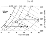
- FIG. 3 is a graph illustrating the temperature distribution of humid air used in the dehumidifying cooling device.
- a dehumidifying cooling operation carried out in the dry channel 115 circulated air from the conditioning space CS, which is mixed with high-temperature and high-humidity outside air, is introduced into the dry channel 115 of the case 110 through the circulated air suction hole 116 under the operation of the air supply blower 180. After passing through the second filter 170, the introduced circulated air sequentially passes through the dehumidifying wheel 150 such that the moisture contained in the circulated air is removed by the adsorbent.
- the dehumidified circulated air is heated by adsorptive heat generated from the surface of the dehumidifying wheel 150.
- the resulting high-temperature and low-humidity circulated air is heat exchanged with the outside air in the wet channel 111 by the sensible heat exchanger 130. Thereby, the circulated air is changed to the low-temperature air prior to being introduced into the regenerative-evaporative cooler 190.
- the circulated air is introduced into the regenerative-evaporative cooler 190, 70% of the circulated air is cooled while passing through the regenerative-evaporative cooler 190, and 30% of the circulated air is discharged to the outside through the cooler exhaust hole 118.
- the circulated air having passed through the regenerative-evaporative cooler 190, is secondarily cooled while passing through the direct-evaporative cooler 200, thereby being supplied into the conditioning space CS through the air supply hole 117 of the case 110.
- the temperature of the outside air is further raised by hot water supplied into the heating coil 140.
- the outside air to be delivered into the dehumidifying wheel 150 has a significantly raised temperature.
- the dehumidifying wheel 150 rotates in a state of adsorbing moisture therein, the outside air forcibly evaporates moisture thereof while passing through the dehumidifying wheel 150, and thereafter, is discharged to the outside through the exhaust hole 112.
- the surface of the dehumidifying wheel 150 is returned to an original dried state thereof, thereby recovering a dehumidifying ability thereof.
- the dehumidifying cooling device for district heating if circulated air 1 is introduced into the case, the circulated air 1 is mixed with outside air 7, to produce mixed air 2 having a raised temperature and absolute humidity. While passing through the dehumidifying wheel, the mixed air 2 is changed to higher-temperature and lower absolute-humidity air 3.
- the air 3 is heat exchanged with outside air 8 in the wet channel while passing through the sensible heat exchanger such that the heat exchanged air 4 has a slight drop only in temperature.
- the temperature of the air 4 is rapidly lowered to produce significantly cooled air 5.
- the temperature of the air 5 is further lowered slightly, but the absolute humidity of the air 5 is raised, thereby resulting in cooling air 6.
- the filtered air 8 has the same temperature and absolute humidity as those of the air 7.
- the air 8 is heat exchanged with the circulated air 3 in the dry channel while passing through the sensible heat exchanger.
- the resulting heat exchanged air 9 is slightly raised in temperature, but keeps the same absolute humidity as that of the air 8. Then, the temperature of the air 9 is rapidly raised while passing through the heating coil, resulting in high-temperature air 10.
- the air 10 is dropped in temperature, but raised in absolute humidity in the course of passing through the dehumidifying wheel, thereby being changed to low-temperature and high-humidity air 11.
- the dehumidifying cooling device for district heating air to be supplied into a conditioning indoor space is subjected to the transfer of heat and moisture via a direct contact with the dehumidifying cooling device.
- This has the effect of achieving excellent transfer efficiency and producing and supplying cooling air with a low-temperature heating source of 60°C.
- the dehumidifying cooling device is operable in the atmospheric pressure state and has a simplified configuration, resulting in a considerable reduction of manufacturing costs.
- a dehumidifying cooling device can be installed to residential and business buildings, etc. using hot water delivered from district heating facilities, so as to utilize the hot water as a source for cooling a room.
Landscapes
- Engineering & Computer Science (AREA)
- Mechanical Engineering (AREA)
- General Engineering & Computer Science (AREA)
- Chemical & Material Sciences (AREA)
- Combustion & Propulsion (AREA)
- Physics & Mathematics (AREA)
- Thermal Sciences (AREA)
- Central Air Conditioning (AREA)
Description
- The present invention relates to a dehumidifying cooling device for district heating, and more particularly, to a dehumidifying cooling device for district heating which can carry out an air cooling operation by use of hot water supplied by large-scale or small-scale district heating systems and gas or oil boilers installed in individual households.
- There is spreading a prospect that the recent high oil price situation is not a temporary problem, but is continuously maintained and fixed. Thereby, main energy consuming countries of the world increasingly take a great effort for securing stable energy resources. With the effectuation of the Tokyo protocol dealing with a reduction in the discharge of greenhouse gas for the sake of preventing global warming, it will be expected that an international pressure about the use limit of fossil energy, the criterion of energy efficiency, etc. will be strengthened.
- According to the published energy report, the amount of energy consumed in domestic and business fields of Korean in 2003 is approximately 55 millions TOE a year, and occupies 25.2% of the total national consumption energy. This rate also corresponds to 41.9% on the basis of electricity. For the past four years, the energy consumption of domestic and business fields shows an average annual rate of increase of 5.3%, whereas the consumption of electricity shows an average annual rate of increase of 12%. Accordingly, it will be appreciated that the consumption of electricity particularly has a rapid increase. Estimating on the basis of a variation in the monthly energy consumption of residential buildings and sample survey results about non-residential buildings as the subject of energy controlment, it is analyzed that 50% of the energy consumption of residential buildings and 47% of the energy consumption of business buildings are used for air conditioning. In conclusion, of the energy consumption of buildings, energy required for air conditioning occupies 13% of the national total energy consumption of Korea.
- Accordingly, to guarantee the efficient use of energy and the continuous development of energy industry while observing related international agreements, it is necessary to improve the use efficiency of energy for air conditioning in domestic and business fields. From this viewpoint, there is put in force a so-called collective-energy industry in which thermal energy and electricity, generated from energy generation facilities concentrated on a specific place for improving the use efficiency of energy in domestic and business fields, are supplied collectively to a plurality of users in residential and business areas. It is reported that the collective-energy industry utilizes waste heat occurred during power generation as a heating source for space heating and hot water heating, thereby achieving not only a reduction of energy by approximately 20 to 30% by virtue of an improved use efficiency of energy, but also an improvement of air environment by approximately 30 to 40% by virtue of a reduction usage of fuel and intensive environmental managements. The collective-energy industry is evaluated as an effective industry capable of dealing with related international environmental restrictions including a climatic change convention, etc. In the affirmative evaluation's debt, in Korea, approximately 1.2 million families share in the benefits of district heating in 2003, and in particular, 85% of supplied energy is generated by combined heat and power generation. Korea has a plan to expand the propagation range of district heating to 2 million families by 2010.
- In the combined heat and power generation, namely, cogeneration, the generation ratio of electricity to heat is fixed at 3 : 5. Therefore, it is important to keep the ratio of electricity to heat at an appropriate level for maximizing the effect of the collective-energy industry. In Korea, the above mentioned generation ratio can be fulfilled in winter, but the summer of Korea has an increased electricity load for air cooling and substantially no heat load. As a result, the operation rate of distinct heating in summer decreases to less than 10%, and this causes a deterioration in the economical efficiency of cogeneration. Actually, no generation results reported between June and September in 2003.
- To improve the operation rate of collective-energy generation facilities for sufficiently utilizing the effects of the industry, excavating the demand of heat in summer is necessary, and in particular, development and propagation of a technology for supplying cooling energy using distinct heating facilities is necessary.
- In one example of the above described cooling energy supply technology, an absorption chiller is installed to a receptor, such as a large-scale building, etc. such that the chiller performs a central cooling operation using energy delivered from distinct heating facilities.
- The absorption chiller is designed to chill water flowing in a pipe by use of heat generated during the evaporation of a liquid-phase refrigerant and condense the evaporated gas-phase refrigerant for the reuse thereof.
- However, despite of various researches and developments for improving the performance thereof, the absorption chiller has a limit in the improvement of performance due to a low temperature of a heating source. In addition, the absorption chiller has an uneconomical high water return temperature because it cannot use water having a temperature of 80°C or less, and suffers from a little difference between the temperature of supplied water and the temperature of water to be returned.
- When the absorption chiller is installed to an apartment, etc. occupying the most part of district heating, so as to carry out a central cooling operation, there is a problem in that cold water pipes have to be additionally installed regardless of hot water supply pipes.
- Therefore, the present invention has been made in view of the above problems, and it is an object of the present invention to provide a above mentioned generation ratio can be fulfilled in winter, but the summer of Korea has an increased electricity load for air cooling and substantially no heat load. As a result, the operation rate of distinct heating in summer decreases to less than 10%, and this causes a deterioration in the economical efficiency of cogeneration. Actually, no generation results reported between June and September in 2003.
- To improve the operation rate of collective-energy generation facilities for sufficiently utilizing the effects of the industry, excavating the demand of heat in summer is necessary, and in particular, development and propagation of a technology for supplying cooling energy using distinct heating facilities is necessary.
- In one example of the above described cooling energy supply technology, an absorption chiller is installed to a receptor, such as a large-scale building, etc. such that the chiller performs a central cooling operation using energy delivered from distinct heating facilities.
- The absorption chiller is designed to chill water flowing in a pipe by use of heat generated during the evaporation of a liquid-phase refrigerant and condense the evaporated gas-phase refrigerant for the reuse thereof.
-
US 5,943 874 A discloses a dehumidifying cooling device having a wet channel, a dry channel, a sensible heat exchanger, a heating coil, and a dehumidifying wheel according to the preamble ofclaim 1. -
US 6,003,327 A discloses an air conditioning system for conditioning a process stream of air wherein the air is dehumidified and cooled to provide a conditional stream of air, the system comprised off and adsorption wheel, means for passing a first portion and a second portion, a heat exchanger in fluid communication with said adsorption wheel, and a heater. Further, an indirect evaporative cooler is connected to the heater to receive air therefrom. An output of the indirect evaporative cooler is connected to a direct evaporative cooler which supplies air to a conditioned space. - Worek W.M. et al.: "Advances in Heat-Activated Cooling Systems", Mechanical Engineering, ASME, New York, US, Col. 118, No. 8, 01.08.996, page 54/55, XP000622353 discloses heat-activated cooling systems having evaporative coolers and regeneration heaters.
- supply hole and the sensible heat exchanger and serving to cool the circulated air in the dry channel, which was dehumidified to high-temperature dry air by the dehumidifying wheel and subsequently, heat exchanged and cooled by the sensible heat exchanger, the cooled circulated air being delivered to the air supply hole of the case.
- Preferably, the device further comprises: a direct-evaporative cooler installed in the dry channel at a position in front of the regenerative-evaporative cooler, the direct-evaporative cooler serving to carry out a secondary cooling operation of the circulated air discharged from the regenerative-evaporative cooler.
- Preferably, the device further comprises: a first filter installed between the outside air suction hole and the sensible heat exchanger and serving to remove impurities contained in the outside air; and an exhaust blower installed between the dehumidifying wheel and the exhaust hole and serving to forcibly discharge the outside air from the wet channel through the exhaust hole, wherein the first filter and the exhaust blower are installed in the wet channel.
- Preferably, the device further comprises: a second filter installed between the circulated air suction hole and the dehumidifying wheel and serving to remove impurities contained in the circulated air; and an air supply blower installed between the dehumidifying wheel and the sensible heat exchanger and serving to forcibly discharge the cooled circulated air from the dry channel through the air supply hole, wherein the second filter and the air supply blower are installed in the dry channel.
- Preferably, the case is further provided with a cooler exhaust hole for discharging high-temperature air generated while the regenerative-evaporative cooler carries out a secondary cooling operation.
- Preferably, the amount of the high-temperature air to be discharged through the cooler exhaust hole is 30% of the total circulated air.
- Preferably, the hot water to be introduced into the heating coil is delivered from any one selected from among a cogeneration plant, a heating boiler, a micro-turbine, a small gas engine, a small gas turbine, a gas boiler, and an oil boiler.
- Preferably, the circulated air suctioned through the circulated air suction hole is mixed with the outside air by a predetermined mixing ratio of 7 : 3.
- According to a dehumidifying cooling device for district heating of the present invention having the above described configuration, it is possible to carry out an air cooling operation by use of hot water supplied by large-scale or small-scale district heating systems and gas or oil boilers installed in individual households. Accordingly, the present invention has the effect of achieving a reduced device size via the implementation of the cooling operation under the atmospheric pressure state, and reducing manufacturing costs by virtue of a simplified system configuration.
- The above and other objects, features and other advantages of the present invention will be more clearly understood from the following detailed description taken in conjunction with the accompanying drawings, in which:
-
FIG. 1 is a view illustrating the configuration of a dehumidifying cooling device for district heating according to the present invention; -
FIG. 2 is a view illustrating the flow of air in the dehumidifying cooling device for district heating according to the present invention; and -
FIG. 3 is a graph illustrating the temperature distribution of humid air used in the dehumidifying cooling device for district heating according to the present invention. - Now, the configuration of a dehumidifying cooling device for district heating according to the present invention will be described in detail with reference to the accompanying drawings.
- In the following description of the present invention, a detailed description of known functions and configurations incorporated herein will be omitted when it may make the subject matter of the present invention rather unclear. Also, the terms used in the following description are terms defined taking into consideration the functions obtained in accordance with the present invention. The definitions of these terms should be determined based on the whole content of this specification because they may be changed in accordance with the option of a user or operator or a usual practice.
-
FIG. 1 is a view illustrating the configuration of a dehumidifying cooling device for district heating according to the present invention. - Referring to
FIG. 1 , thedehumidifying cooling device 100 according to the present invention comprises acase 110, afirst filter 120, asensible heat exchanger 130, aheating coil 140, adehumidifying wheel 150, anexhaust blower 160, asecond filter 170, anair supply blower 180, a regenerative-evaporative cooler 190, and a direct-evaporative cooler 200. - The
case 110 is made of a metallic material and has a rectangular box shape. Thecase 110 is installed with apartition 119 to divide the interior of thecase 110 into awet channel 111 and adry channel 115. Thecase 110 has an outsideair suction hole 113 provided at one end of thewet channel 111 for introducing outside air into thewet channel 111 and anexhaust hole 112 provided at the other end of thewet channel 111 for discharging the outside air. Thecase 110 also has a circulatedair suction hole 116 provided at one end of thedry channel 115 for introducing circulated air from a conditioning space CS into thedry channel 115 and anair supply hole 117 provided at the other end of thedry channel 115 for supplying cooling air into the conditioning space CS. Thedry channel 115 of thecase 110 is further provided with acooler exhaust hole 118 for discharging high-temperature air generated while the regenerative-evaporative cooler 190 carries out a secondary cooling operation that will be described hereinafter. The circulated air, introduced into thecase 110 through the circulatedair suction hole 116, is mixed with the outside air at a ratio of 7 : 3, to keep the interior of thecase 110 in the atmospheric pressure state. - The
first filter 120 is located in thewet channel 111 of thecase 110 at a position between the outsideair suction hole 113 and thesensible heat exchanger 130. Thefirst filter 120 is used to remove impurities and bad smell contained in the suctioned outside air. Preferably, thefirst filter 120 is an antibacterial filter, and is easily separable from thecase 110. - The
sensible heat exchanger 130 has arotating shaft 131 installed in the same direction as thepartition 119 and takes the form of a disc to rotate about therotating shaft 131 inside thewet channel 111 and thedry channel 115 of thecase 110. Thesensible heat exchanger 130 is used to heat exchange the outside air introduced into thewet channel 111 through the outsideair suction hole 113 with the circulated air introduced into thedry channel 115. Thesensible heat exchanger 130 takes the form of a honeycomb-patterned disc fabricated by processing a thin plate, such as an aluminum plate, etc. Thesensible heat exchanger 130 carries out a primary heat exchange operation for lowering the temperature of the circulated air that is dehumidified by passing through thedehumidifying wheel 150 that will be described hereinafter. There are provided an additional motor and belt (not shown) for rotation of thesensible heat exchanger 130. - The
heating coil 140 is located in thewet channel 111 of thecase 110 at a position between a rear end of thesensible heat exchanger 130 and theexhaust hole 112. Theheating coil 140 is used to raise the temperature of the outside pair passing through thewet channel 111 by use of heat of hot water introduced thereinto. The hot water introduced into theheating coil 140 is delivered from any one selected from among a cogeneration plant, a heating boiler, a micro-turbine, a small gas engine, a small gas turbine, a gas boiler, and an oil boiler, and has a temperature within a range of 60 to 120 °C. - The
dehumidifying wheel 150 has arotating shaft 151 installed in the same direction as thepartition 119, and takes the form of a disc to rotate about therotating shaft 151 inside thewet channel 111 and thedry channel 115 of thecase 110. Thedehumidifying wheel 150 is located behind theheating coil 140 and serves to adsorb and remove moisture contained in the circulated air within thedry channel 115. Thedehumidifying wheel 150 is regenerated by evaporating the adsorbed moisture to thereby supply the moisture into the high-temperature outside air within thewet channel 111. Thedehumidifying wheel 150 takes the form of a honeycomb-patterned disc containing an adsorbent, such as silica gel, zeolite, or the like, for adsorbing the moisture contained in the circulated air in a dry adsorption manner. There are provided an additional motor and belt (not shown) for rotation of thedehumidifying wheel 150. - The
exhaust blower 160 is installed in thewet channel 111 of thecase 110 at a position between thedehumidifying wheel 150 and theexhaust hole 112, and used to forcibly discharge the outside air from thewet channel 111. - The
second filter 170 is installed in thedry channel 115 of thecase 110 at a position between the circulatedair suction hole 116 and thedehumidifying wheel 150 and used to remove impurities and bad smell contained in the circulated air. Preferably, thesecond filter 170 is an antibacterial filter, and is easily separable from thecase 110. - The
air supply blower 180 is installed in thedry channel 115 of thecase 110 at a position in front of thedehumidifying wheel 150 and used to forcibly discharge the circulated air from thedry channel 115 through the circulatedair supply hole 117. - The regenerative-
evaporative cooler 190 is installed in thedry channel 115 at a position between the circulatedair supply hole 117 and thesensible heat exchanger 130. If the circulated air introduced into thedry channel 115 is dehumidified by thedehumidifying wheel 150 so as to be changed to high-temperature dry air and subsequently, heat exchanged and cooled by thesensible heat exchanger 130, the regenerative-evaporative cooler 190 further cools the circulated air. The cooled circulated air is delivered to theair supply hole 117 of thecase 110, whereas the high-temperature air generated during cooling is delivered to thecooler exhaust hole 118. Here, the amount of the high-temperature air to be discharged through thecooler exhaust hole 118 is 30% of the total circulated air. The interior of the regenerative-evaporative cooler 190 is divided into a dry channel and a wet channel. If a part of the air, passing through the dry channel, is delivered into the wet channel, the air is cooled as water is evaporated by the high-temperature surface of the wet channel, thereby acting to absorb heat from the remaining higher temperature air passing through the dry channel. Thereby, the air passing through the dry channel can be cooled to a dew-point temperature to the maximum extent without an increase of humidity. The configuration of the regenerative-evaporative cooler 190 is disclosed in Korea Patent Registration No.0409265 - The direct-
evaporative cooler 200 is installed in thedry channel 115 of thecase 110 at a position in front of the regenerative-evaporative cooler 190. The direct-evaporative cooler 200 serves to carry out a secondary cooling operation of the circulated air from the regenerative-evaporative cooler 190, so as to supply the resulting air into the conditioning space CS through theair supply hole 117 of thecase 110. - Hereinafter, the operation and effects of the dehumidifying cooling device for district heating according to the present invention will be described in detail with reference to
FIGS. 1 to 3 . -
FIG. 2 is a view illustrating the flow of air in the dehumidifying cooling device for district heating according to the present invention, andFIG. 3 is a graph illustrating the temperature distribution of humid air used in the dehumidifying cooling device. - Explaining first a dehumidifying cooling operation carried out in the
dry channel 115, circulated air from the conditioning space CS, which is mixed with high-temperature and high-humidity outside air, is introduced into thedry channel 115 of thecase 110 through the circulatedair suction hole 116 under the operation of theair supply blower 180. After passing through thesecond filter 170, the introduced circulated air sequentially passes through thedehumidifying wheel 150 such that the moisture contained in the circulated air is removed by the adsorbent. - The dehumidified circulated air is heated by adsorptive heat generated from the surface of the
dehumidifying wheel 150. The resulting high-temperature and low-humidity circulated air is heat exchanged with the outside air in thewet channel 111 by thesensible heat exchanger 130. Thereby, the circulated air is changed to the low-temperature air prior to being introduced into the regenerative-evaporative cooler 190. - If the circulated air is introduced into the regenerative-
evaporative cooler evaporative cooler cooler exhaust hole 118. - The circulated air, having passed through the regenerative-
evaporative cooler 190, is secondarily cooled while passing through the direct-evaporative cooler 200, thereby being supplied into the conditioning space CS through theair supply hole 117 of thecase 110. - Next, explaining a heat-exchange operation carried out in the
wet channel 111, high-temperature and high-humidity outside air is introduced into thewet channel 111 through the outsideair suction hole 113 and passes through thefirst filter 120 under the operation of theexhaust blower 160. Then, the filtered outside air is heat exchanged with the circulated air in thedry channel 115 by thesensible heat exchanger 130 such that the temperature of the outside air is raised. Thereby, the outside air with the raised temperature passes through theheating coil 140. - While passing through the
heating coil 140, the temperature of the outside air is further raised by hot water supplied into theheating coil 140. Thereby, the outside air to be delivered into thedehumidifying wheel 150 has a significantly raised temperature. - As the
dehumidifying wheel 150 rotates in a state of adsorbing moisture therein, the outside air forcibly evaporates moisture thereof while passing through thedehumidifying wheel 150, and thereafter, is discharged to the outside through theexhaust hole 112. Through the above described process, the surface of thedehumidifying wheel 150 is returned to an original dried state thereof, thereby recovering a dehumidifying ability thereof. - Referring to
FIGS. 2 and 3 , in the dehumidifying cooling device for district heating according to the present invention, if circulatedair ① is introduced into the case, the circulatedair ① is mixed with outside air ⑦, to produce mixed air ② having a raised temperature and absolute humidity. While passing through the dehumidifying wheel, the mixed air ② is changed to higher-temperature and lower absolute-humidity air ③. - Then, the
air ③ is heat exchanged withoutside air ⑧ in the wet channel while passing through the sensible heat exchanger such that the heat exchangedair ④ has a slight drop only in temperature. In sequence, while passing through the regenerative-evaporative cooler, the temperature of theair ④ is rapidly lowered to produce significantly cooled air ⑤. Thereafter, while passing through the direct-evaporative cooler, the temperature of the air ⑤ is further lowered slightly, but the absolute humidity of the air ⑤ is raised, thereby resulting in coolingair ⑥. - Meanwhile, when the introduced outside air ⑦ passes through the first filter, the filtered
air ⑧ has the same temperature and absolute humidity as those of the air ⑦. Theair ⑧ is heat exchanged with the circulatedair ③ in the dry channel while passing through the sensible heat exchanger. The resulting heat exchangedair ⑨ is slightly raised in temperature, but keeps the same absolute humidity as that of theair ⑧. Then, the temperature of theair ⑨ is rapidly raised while passing through the heating coil, resulting in high-temperature air ⑩. - The
air ⑩ is dropped in temperature, but raised in absolute humidity in the course of passing through the dehumidifying wheel, thereby being changed to low-temperature and high-humidity air ⑪. - In conclusion, in the dehumidifying cooling device for district heating according to the present invention, air to be supplied into a conditioning indoor space is subjected to the transfer of heat and moisture via a direct contact with the dehumidifying cooling device. This has the effect of achieving excellent transfer efficiency and producing and supplying cooling air with a low-temperature heating source of 60°C. Further, differently from conventional absorptive devices, the dehumidifying cooling device is operable in the atmospheric pressure state and has a simplified configuration, resulting in a considerable reduction of manufacturing costs.
- As apparent from the above description, a dehumidifying cooling device according to the present invention can be installed to residential and business buildings, etc. using hot water delivered from district heating facilities, so as to utilize the hot water as a source for cooling a room.
- Although the preferred embodiments of the present invention have been disclosed for illustrative purposes, those skilled in the art will appreciate that various modifications are possible within the scope of the invention as disclosed in the accompanying claims.
Claims (9)
- A dehumidifying cooling device for district heating comprising:- a case (110) having a partition (119) to divide the interior of the case (110) into a wet channel (111) and a dry channel (115), the wet channel (111) being provided, at one end thereof, with an outside air suction hole (113) for introducing outside air into the wet channel (111) and, at the other end thereof, with an exhaust hole (112) for discharging the outside air, the dry channel (115) being provided, at one end thereof, with a circulated air suction hole (116) for introducing circulated air from a conditioning space into the dry channel (115) and, at the other end thereof, with an air supply hole for supplying cooling air into the conditioning space;- a sensible heat exchanger (130) configured to rotate about the partition (119) and serving to heat exchange the outside air, introduced into the wet channel (111) through the outside air suction hole (113), with the circulated air introduced into the dry channel (115);- a heating coil (140) installed in the wet channel (111) at a position between a rear end of the sensible heat exchanger (130) and the exhaust hole (112) and serving to raise the temperature of the outside air passing through the wet channel (111) by use of heat of hot water introduced into the heating coil (140);- a dehumidifying wheel (150) configured to rotate about the partition (119) at a position behind the heating coil (140) and serving to adsorb and remove moisture contained in the circulated air within the dry channel (115), the dehumidifying wheel (150) being regenerated by evaporating the adsorbed moisture to thereby supply the evaporated moisture into the high-temperature outside air in the wet channel (111); characterized by- a regenerative-evaporative cooler (190) installed in the dry channel (115) at a position between the circulated air supply hole and the sensible heat exchanger (130) and serving to cool the circulated air in the dry channel (115), which was dehumidified to high-temperature dry air by the dehumidifying wheel (150) and subsequently, heat exchanged and cooled by the sensible heat exchanger (130), the cooled circulated air being delivered to the air supply hole of the case (110).
- The device according to claim 1, further comprising:- a direct-evaporative cooler (200) installed in the dry channel (115) at a position in front of the regenerative-evaporative cooler (190), the direct-evaporative cooler (200) serving to carry out a secondary cooling operation of the circulated air discharged from the regenerative-evaporative cooler (190).
- The device according to claim 1, further comprising:- a first filter (120) installed between the outside air suction hole (113) and the sensible heat exchanger (130) and serving to remove impurities contained in the outside air; and- an exhaust blower installed between the dehumidifying wheel (150) and the exhaust hole (112) and serving to forcibly discharge the outside air from the wet channel (111) through the exhaust hole (112), wherein the first filter (120) and the exhaust blower are installed in the wet channel (111).
- The device according to claim 1, further comprising:- a second filter (170) installed between the circulated air suction hole (116) and the dehumidifying wheel (150) and serving to remove impurities contained in the circulated air; and- an air supply blower (180) installed between the dehumidifying wheel (150) and the sensible heat exchanger (130) and serving to forcibly discharge the cooled circulated air from the dry channel (115) through the air supply hole, wherein the second filter (170) and the air supply blower (180) are installed in the dry channel (115).
- The device according to claim 1, wherein the case (110) further has a cooler exhaust hole (118) provided at the dry channel (115) for discharging high-temperature air generated while the regenerative-evaporative cooler (190) carries out a secondary cooling operation.
- The device according to claim 5, wherein the amount of the high- temperature air to be discharged through the cooler exhaust hole (118) is 30% of the total circulated air.
- The device according to claim 1, wherein the hot water to be introduced into the heating coil (140) is delivered from any one selected from among a cogeneration plant, a heating boiler, a micro-turbine, a small gas engine, a small gas turbine, a gas boiler, and an oil boiler.
- The device according to claim 1, wherein the circulated air suctioned through the circulated air suction hole (116) is mixed with the outside air by a predetermined mixing ratio.
- The device according to claim 1, wherein the predetermined mixing ratio of the circulated air to the outside air is 7 : 3.
Applications Claiming Priority (2)
| Application Number | Priority Date | Filing Date | Title |
|---|---|---|---|
| KR1020070010671A KR100773434B1 (en) | 2007-02-01 | 2007-02-01 | Dehumidification air conditioner for district heating |
| PCT/KR2007/001147 WO2008041787A1 (en) | 2007-02-01 | 2007-03-08 | Dehumidifying cooling device for district heating |
Publications (3)
| Publication Number | Publication Date |
|---|---|
| EP1943468A1 EP1943468A1 (en) | 2008-07-16 |
| EP1943468A4 EP1943468A4 (en) | 2013-12-25 |
| EP1943468B1 true EP1943468B1 (en) | 2017-04-26 |
Family
ID=39060870
Family Applications (1)
| Application Number | Title | Priority Date | Filing Date |
|---|---|---|---|
| EP07715547.1A Ceased EP1943468B1 (en) | 2007-02-01 | 2007-03-08 | Dehumidifying cooling device for district heating |
Country Status (8)
| Country | Link |
|---|---|
| US (1) | US20100212345A1 (en) |
| EP (1) | EP1943468B1 (en) |
| JP (1) | JP2009530585A (en) |
| KR (1) | KR100773434B1 (en) |
| CN (1) | CN101346589B (en) |
| MY (1) | MY151691A (en) |
| SA (1) | SA08290040B1 (en) |
| WO (1) | WO2008041787A1 (en) |
Families Citing this family (19)
| Publication number | Priority date | Publication date | Assignee | Title |
|---|---|---|---|---|
| KR101180180B1 (en) | 2010-06-17 | 2012-09-05 | 황혜자 | Drying system using distribution heating facility or fuel cell facility of house |
| US9435551B2 (en) * | 2011-09-15 | 2016-09-06 | Khanh Dinh | Dehumidifier dryer using ambient heat enhancement |
| KR101207947B1 (en) * | 2011-12-19 | 2012-12-05 | 한국과학기술연구원 | Apparatus for dehumidifying and cooling air |
| US10393443B1 (en) * | 2013-09-23 | 2019-08-27 | Neal Energy Management, Llc | Rooftop packaged heating, ventilating and air conditioning system utilizing phase change materials |
| KR101436613B1 (en) * | 2013-10-29 | 2014-11-05 | 한국지역난방공사 | Dehumidified cooling system for district cooling with cooling, ventilation and humidification |
| TWI480496B (en) * | 2013-11-20 | 2015-04-11 | Ind Tech Res Inst | A drying device for regenerating compressed air by electrical heating and a desiccant regeneration unit |
| CN103791592B (en) * | 2014-02-25 | 2016-04-13 | 上海理工大学 | For the cool-down dehumidification method of warm and humid autonomous control system |
| KR101560823B1 (en) * | 2014-04-21 | 2015-10-16 | 주식회사 경동나비엔 | Hybrid type heat pump device |
| KR101655370B1 (en) | 2014-11-24 | 2016-09-08 | 한국과학기술연구원 | Desiccant cooling system |
| KR101749194B1 (en) * | 2015-11-18 | 2017-06-20 | 주식회사 경동나비엔 | Air-conditioner capable of heating and humidity control and the method thereof |
| KR101782839B1 (en) * | 2015-11-18 | 2017-10-23 | 주식회사 경동나비엔 | Air-conditioner capable of cooling and humidity control and the method thereof |
| KR101664791B1 (en) * | 2015-11-18 | 2016-10-12 | 주식회사 경동나비엔 | Air-conditioner capable of ventilation and humidity control and the method thereof |
| US10834855B2 (en) * | 2016-01-08 | 2020-11-10 | Nortek Air Solutions Canada, Inc. | Integrated make-up air system in 100% air recirculation system |
| US10578348B2 (en) * | 2017-01-18 | 2020-03-03 | Heatcraft Refrigeration Products Llc | System and method for reducing moisture in a refrigerated room |
| KR101933555B1 (en) * | 2017-04-12 | 2018-12-31 | 한국과학기술연구원 | Absorption hybrid deciccant colling system |
| KR101981786B1 (en) * | 2018-01-25 | 2019-08-28 | 김정열 | Air conditioning system and method for improving air conditioning efficiency |
| KR102559533B1 (en) * | 2021-05-31 | 2023-07-26 | 주식회사 휴마스터 | Thermo hygrostat and control method thereof |
| CN114777391B (en) * | 2022-04-27 | 2023-06-06 | 青岛澳柯玛生物医疗有限公司 | Dehumidification function system |
| CN118310105B (en) * | 2024-04-18 | 2025-02-25 | 广东海洋大学 | Evaporative cooling device and method for heat-driven rotary dehumidification |
Family Cites Families (30)
| Publication number | Priority date | Publication date | Assignee | Title |
|---|---|---|---|---|
| US5170633A (en) * | 1991-06-24 | 1992-12-15 | Amsted Industries Incorporated | Desiccant based air conditioning system |
| KR950003071B1 (en) * | 1992-10-21 | 1995-03-30 | 주식회사 신성엔지니어링 | Air conditioning system |
| US5758509A (en) * | 1995-12-21 | 1998-06-02 | Ebara Corporation | Absorption heat pump and desiccant assisted air conditioning apparatus |
| US5758508A (en) * | 1996-02-05 | 1998-06-02 | Larouche Industries Inc. | Method and apparatus for cooling warm moisture-laden air |
| US5660048A (en) * | 1996-02-16 | 1997-08-26 | Laroche Industries, Inc. | Air conditioning system for cooling warm moisture-laden air |
| JP3115991B2 (en) * | 1996-03-05 | 2000-12-11 | 鹿島建設株式会社 | Secondary system of district cooling and heating system |
| JP2791947B2 (en) * | 1996-05-31 | 1998-08-27 | 株式会社新来島どっく | Heat exchange type dehumidifier |
| US6029467A (en) * | 1996-08-13 | 2000-02-29 | Moratalla; Jose M. | Apparatus for regenerating desiccants in a closed cycle |
| JPH1096542A (en) * | 1996-09-24 | 1998-04-14 | Ebara Corp | Air conditioning system |
| JP2968232B2 (en) * | 1997-04-11 | 1999-10-25 | 株式会社荏原製作所 | Air conditioning system and operating method thereof |
| JP2968241B2 (en) * | 1997-10-24 | 1999-10-25 | 株式会社荏原製作所 | Dehumidifying air conditioning system and operating method thereof |
| JPH11197439A (en) * | 1998-01-14 | 1999-07-27 | Ebara Corp | Dehumidification air-conditioner |
| JPH11262621A (en) * | 1998-03-17 | 1999-09-28 | Ebara Corp | Dehumidifying air conditioner |
| JP3078280B1 (en) * | 1999-05-28 | 2000-08-21 | 株式会社ア−スクリ−ン東北 | Energy-saving air-conditioning method, device and method of use |
| KR200197787Y1 (en) | 2000-04-28 | 2000-09-15 | 주식회사유한프랜트 | Absorption humidifying simultaneous heating using waste heat of adsorptive rotary air conditioner |
| JP2002013759A (en) * | 2000-06-28 | 2002-01-18 | Earth Clean Tohoku:Kk | Desiccant air conditioning method |
| KR100409265B1 (en) * | 2001-01-17 | 2003-12-18 | 한국과학기술연구원 | Regenerative evaporative cooler |
| JP2003130391A (en) * | 2001-10-18 | 2003-05-08 | Sanyo Electric Co Ltd | Air conditioner |
| DE10220631A1 (en) * | 2002-05-10 | 2003-11-20 | Loeffler Michael | Process for sorption air conditioning with process control in a heat exchanger |
| CN2553289Y (en) * | 2002-05-17 | 2003-05-28 | 无锡沙漠除湿设备厂 | Self-circulating rotary-wheel humidifier |
| US6751964B2 (en) * | 2002-06-28 | 2004-06-22 | John C. Fischer | Desiccant-based dehumidification system and method |
| JP2004069222A (en) * | 2002-08-08 | 2004-03-04 | Matsushita Ecology Systems Co Ltd | Ventilation and humidity controller |
| JP2004085096A (en) * | 2002-08-27 | 2004-03-18 | Univ Waseda | Hybrid desiccant air conditioning system |
| JP4103563B2 (en) * | 2002-11-29 | 2008-06-18 | ダイキン工業株式会社 | Air conditioner |
| US6854279B1 (en) * | 2003-06-09 | 2005-02-15 | The United States Of America As Represented By The Secretary Of The Navy | Dynamic desiccation cooling system for ships |
| CN2786484Y (en) * | 2004-08-10 | 2006-06-07 | 张建岗 | Low dew point dehumidifying and drying system |
| KR100550575B1 (en) | 2004-08-17 | 2006-02-10 | 엘지전자 주식회사 | Power generation air conditioning system with dehumidifier |
| JP2006071168A (en) * | 2004-09-01 | 2006-03-16 | Sanden Corp | Air conditioner |
| CN100483041C (en) * | 2004-09-29 | 2009-04-29 | 上海交通大学 | Over critical CO2 refrigeration and rotary wheel dehumidifying combined air conditioning system |
| CN2856798Y (en) * | 2005-10-28 | 2007-01-10 | 赖幸慈 | Chemical dehumidifier with regeneration air outlet cooling device |
-
2007
- 2007-02-01 KR KR1020070010671A patent/KR100773434B1/en active Active
- 2007-03-08 EP EP07715547.1A patent/EP1943468B1/en not_active Ceased
- 2007-03-08 MY MYPI20080236 patent/MY151691A/en unknown
- 2007-03-08 CN CN2007800008868A patent/CN101346589B/en not_active Expired - Fee Related
- 2007-03-08 WO PCT/KR2007/001147 patent/WO2008041787A1/en not_active Ceased
- 2007-03-08 JP JP2009501341A patent/JP2009530585A/en active Pending
- 2007-03-08 US US11/989,964 patent/US20100212345A1/en not_active Abandoned
-
2008
- 2008-01-30 SA SA08290040A patent/SA08290040B1/en unknown
Also Published As
| Publication number | Publication date |
|---|---|
| US20100212345A1 (en) | 2010-08-26 |
| EP1943468A4 (en) | 2013-12-25 |
| CN101346589B (en) | 2010-06-02 |
| JP2009530585A (en) | 2009-08-27 |
| EP1943468A1 (en) | 2008-07-16 |
| SA08290040B1 (en) | 2012-02-22 |
| CN101346589A (en) | 2009-01-14 |
| MY151691A (en) | 2014-06-30 |
| WO2008041787A1 (en) | 2008-04-10 |
| KR100773434B1 (en) | 2007-11-05 |
Similar Documents
| Publication | Publication Date | Title |
|---|---|---|
| EP2078175B1 (en) | Dehumidifying cooling device for district heating | |
| US20100212345A1 (en) | Dehumidifying Cooling Device for District Heating | |
| Rafique et al. | A review on desiccant based evaporative cooling systems | |
| CN103502740B (en) | Hybrid refrigeration device | |
| KR20110092773A (en) | Hybrid air conditioning system | |
| Hwang et al. | In-depth analysis of the performance of hybrid desiccant cooling system incorporated with an electric heat pump | |
| US9383116B2 (en) | Dehumidification apparatus, and air conditioning apparatus and air conditioning system having the same | |
| KR101441486B1 (en) | Cooling apparatus using an absorption refrigerator and a desiccant cooling system | |
| Khoukhi et al. | Performance of desiccant-based cooling systems in hot-humid climates: A review | |
| JP2003279070A (en) | Hybrid desiccant air conditioning system | |
| KR100780068B1 (en) | Dehumidification cooling system using dehumidification air conditioner | |
| JPH10300128A (en) | Cooling/dehumidifying apparatus of refrigerant natural circulation type air air-conditioning apparatus combinedly provided therewith | |
| KR950003070B1 (en) | Hybrid air condition system | |
| KR950003071B1 (en) | Air conditioning system | |
| JP2002282641A (en) | Dehumidifying air conditioner | |
| JP2008304113A (en) | Humidifying air-conditioning system | |
| CN202902470U (en) | Refrigeration and turning wheel absorption and coupling operated dehumidification device | |
| Rajab et al. | Investigation of the performance of heat pump waste heat regeneration runner dehumidification of air conditioning systems | |
| CN201764591U (en) | Dehumidifier | |
| Al-Ahmedi | Solar air conditioning system using desiccant wheel technology as a solution for Iraq | |
| Ukai et al. | Comparison of performance of desiccant air handling unit with solar thermal system under various control methods | |
| Kale Pranay et al. | A Review on Design and Development of Three In One Air Cooling System | |
| Khaira et al. | Performance evaluation of novel and efficient integration of solar-assisted HVAC system with solar humidification-dehumidification desalination system | |
| JP2002061891A (en) | Waste heat utilization device |
Legal Events
| Date | Code | Title | Description |
|---|---|---|---|
| PUAI | Public reference made under article 153(3) epc to a published international application that has entered the european phase |
Free format text: ORIGINAL CODE: 0009012 |
|
| 17P | Request for examination filed |
Effective date: 20080215 |
|
| AK | Designated contracting states |
Kind code of ref document: A1 Designated state(s): AT BE BG CH CY CZ DE DK EE ES FI FR GB GR HU IE IS IT LI LT LU LV MC MT NL PL PT RO SE SI SK TR |
|
| AX | Request for extension of the european patent |
Extension state: AL BA HR MK RS |
|
| RBV | Designated contracting states (corrected) |
Designated state(s): DE FR GB |
|
| DAX | Request for extension of the european patent (deleted) | ||
| RBV | Designated contracting states (corrected) |
Designated state(s): DE FR GB |
|
| A4 | Supplementary search report drawn up and despatched |
Effective date: 20131122 |
|
| RIC1 | Information provided on ipc code assigned before grant |
Ipc: F24F 3/14 20060101AFI20131118BHEP |
|
| GRAP | Despatch of communication of intention to grant a patent |
Free format text: ORIGINAL CODE: EPIDOSNIGR1 |
|
| INTG | Intention to grant announced |
Effective date: 20161013 |
|
| GRAS | Grant fee paid |
Free format text: ORIGINAL CODE: EPIDOSNIGR3 |
|
| GRAA | (expected) grant |
Free format text: ORIGINAL CODE: 0009210 |
|
| AK | Designated contracting states |
Kind code of ref document: B1 Designated state(s): DE FR GB |
|
| REG | Reference to a national code |
Ref country code: GB Ref legal event code: FG4D |
|
| REG | Reference to a national code |
Ref country code: DE Ref legal event code: R096 Ref document number: 602007050753 Country of ref document: DE |
|
| REG | Reference to a national code |
Ref country code: DE Ref legal event code: R082 Ref document number: 602007050753 Country of ref document: DE Representative=s name: EISENFUEHR SPEISER PATENTANWAELTE RECHTSANWAEL, DE |
|
| REG | Reference to a national code |
Ref country code: DE Ref legal event code: R097 Ref document number: 602007050753 Country of ref document: DE |
|
| PLBE | No opposition filed within time limit |
Free format text: ORIGINAL CODE: 0009261 |
|
| STAA | Information on the status of an ep patent application or granted ep patent |
Free format text: STATUS: NO OPPOSITION FILED WITHIN TIME LIMIT |
|
| REG | Reference to a national code |
Ref country code: FR Ref legal event code: PLFP Year of fee payment: 12 |
|
| 26N | No opposition filed |
Effective date: 20180129 |
|
| PGFP | Annual fee paid to national office [announced via postgrant information from national office to epo] |
Ref country code: GB Payment date: 20220324 Year of fee payment: 16 |
|
| PGFP | Annual fee paid to national office [announced via postgrant information from national office to epo] |
Ref country code: FR Payment date: 20220322 Year of fee payment: 16 |
|
| PGFP | Annual fee paid to national office [announced via postgrant information from national office to epo] |
Ref country code: DE Payment date: 20220406 Year of fee payment: 16 |
|
| REG | Reference to a national code |
Ref country code: DE Ref legal event code: R119 Ref document number: 602007050753 Country of ref document: DE |
|
| GBPC | Gb: european patent ceased through non-payment of renewal fee |
Effective date: 20230308 |
|
| PG25 | Lapsed in a contracting state [announced via postgrant information from national office to epo] |
Ref country code: GB Free format text: LAPSE BECAUSE OF NON-PAYMENT OF DUE FEES Effective date: 20230308 |
|
| PG25 | Lapsed in a contracting state [announced via postgrant information from national office to epo] |
Ref country code: GB Free format text: LAPSE BECAUSE OF NON-PAYMENT OF DUE FEES Effective date: 20230308 Ref country code: FR Free format text: LAPSE BECAUSE OF NON-PAYMENT OF DUE FEES Effective date: 20230331 Ref country code: DE Free format text: LAPSE BECAUSE OF NON-PAYMENT OF DUE FEES Effective date: 20231003 |