EP1943407B1 - Backhead and drill assembly with backhead - Google Patents
Backhead and drill assembly with backhead Download PDFInfo
- Publication number
- EP1943407B1 EP1943407B1 EP06827334.1A EP06827334A EP1943407B1 EP 1943407 B1 EP1943407 B1 EP 1943407B1 EP 06827334 A EP06827334 A EP 06827334A EP 1943407 B1 EP1943407 B1 EP 1943407B1
- Authority
- EP
- European Patent Office
- Prior art keywords
- piston
- backhead
- drill assembly
- wear sleeve
- area
- Prior art date
- Legal status (The legal status is an assumption and is not a legal conclusion. Google has not performed a legal analysis and makes no representation as to the accuracy of the status listed.)
- Active
Links
- 238000005553 drilling Methods 0.000 claims description 52
- 239000012530 fluid Substances 0.000 claims description 28
- 238000007789 sealing Methods 0.000 claims description 5
- 238000000926 separation method Methods 0.000 claims description 3
- 230000007423 decrease Effects 0.000 description 4
- 239000000463 material Substances 0.000 description 4
- 239000011435 rock Substances 0.000 description 3
- 230000007704 transition Effects 0.000 description 3
- 239000011800 void material Substances 0.000 description 2
- 238000004891 communication Methods 0.000 description 1
- 238000010276 construction Methods 0.000 description 1
- 230000003247 decreasing effect Effects 0.000 description 1
- 238000003754 machining Methods 0.000 description 1
- 239000007787 solid Substances 0.000 description 1
Images


Classifications
-
- E—FIXED CONSTRUCTIONS
- E21—EARTH OR ROCK DRILLING; MINING
- E21B—EARTH OR ROCK DRILLING; OBTAINING OIL, GAS, WATER, SOLUBLE OR MELTABLE MATERIALS OR A SLURRY OF MINERALS FROM WELLS
- E21B4/00—Drives for drilling, used in the borehole
- E21B4/06—Down-hole impacting means, e.g. hammers
- E21B4/14—Fluid operated hammers
-
- E—FIXED CONSTRUCTIONS
- E21—EARTH OR ROCK DRILLING; MINING
- E21B—EARTH OR ROCK DRILLING; OBTAINING OIL, GAS, WATER, SOLUBLE OR MELTABLE MATERIALS OR A SLURRY OF MINERALS FROM WELLS
- E21B10/00—Drill bits
Definitions
- US 5,685,380 discloses another portion of a drill assembly, where a piston is slidably movable within a cylinder that is separate from the backhead.
- the securing member can comprise a laterally extending pin inserted through at least one opening in the backhead.
- the securing member can comprise at least two laterally extending pins, each of the pins being inserted through one of a corresponding number of spaced-apart openings in the backhead.
- the backhead assembly 12 includes a backhead 24 and a distributor or check valve assembly 26.
- the backhead 24 is an elongate member having an exposed proximal end 28 with a connection 30 for attachment to a source of pressurized fluid.
- the backhead 24 also has a tool receiving portion 32 shaped to receive a tool, e.g., a wrench, to assist in installing and removing the backhead. Adjacent the tool receiving portion 32 is a threaded portion 34. In the illustrated embodiment, an outer diameter of the backhead is stepped down at a shoulder 33 immediately adjacent the threaded portion 34.
- Fig. 8A and Fig. 8B are section views in elevation showing the conventional drilling tool and a drilling tool according to an embodiment of this application, respectively, in the impact position, i.e., when the piston has contacted the bit, which in turn exerts an impact on any material with which the bit is in contact.
- Figs. 9A and 9B are similar to Figs. 8A and 8B , but shown the respective drilling tools in a drop open position, when the tools have been brought to rest, such as, e.g., if a void is encountered while drilling.
- Figs. 10A and 10B are similar to Figs. 8A and 8B , but show the respective drilling tools in a position when the piston is at the top of its stroke, i.e., withdrawn in the distal direction.
- the flow path 80 is substantially free of sharp bends, loss of energy due to friction and decreases in velocity are reduced. Stated differently, the flow path 80 is much more energy efficient than the flow path 180 in the conventional drilling tool 110. In addition, the flow path 80 does not force the intake flow through any apertures or other bounded openings at sharp angles to the flow's primary direction. Also, the intake flow passes along walls (e.g., the outer periphery of the backhead 24) rather than through them (compare the conventional drilling tool 110, where the intake flow must pass through the inner cylinder 113).
Landscapes
- Engineering & Computer Science (AREA)
- Life Sciences & Earth Sciences (AREA)
- Geology (AREA)
- Mining & Mineral Resources (AREA)
- Mechanical Engineering (AREA)
- Physics & Mathematics (AREA)
- Environmental & Geological Engineering (AREA)
- Fluid Mechanics (AREA)
- General Life Sciences & Earth Sciences (AREA)
- Geochemistry & Mineralogy (AREA)
- Earth Drilling (AREA)
Description
- This application relates to drilling equipment, and in particular to an improved construction of a fluid-operated drilling tool.
- Known types of fluid-operated drilling tools, particularly "down-the-hole" rock drilling tools, generally have one end connected to a source of pressurized fluid (referred to here as the proximal end) and an opposite distal or working end with a reciprocating bit that is controlled to strike material to be drilled or removed with high force.
- In a conventional rock drilling tool, the source of pressurized fluid, which is typically compressed air or other gas, is connected to a backhead or top sub at the proximal end of the tool by a pressure fitting. A hollow wear sleeve is attached by a threaded connection to the backhead and extends distally to form the exterior surface or shank of the tool. Within the wear sleeve, there is a distributor with a check valve that selectively supplies pressurized fluid to move the piston.
- Typically, the distributor is secured in place by its attachment to an interior surface of the wear sleeve. According to one known approach, the distributor is received within the bore of an inner cylinder, and the inner cylinder has a surrounding retaining ring that is received in a circumferential groove formed in the interior surface of the wear sleeve. Over time, it becomes necessary to remove the distributor, e.g., to repair or replace it, to replace the wear sleeve to which it is attached and/or to access other components within the wear sleeve, e.g., the piston. In conventional drilling tools, uncoupling the distributor from the wear sleeve is difficult. For example, it can be difficult to access the retaining ring and disengage it from the wear sleeve and/or the distributor.
- In conventional drilling tools, some of the passageways for the pressurized fluid have reduced areas and/or other types of restrictions that decrease flow velocity and efficiency. Some of the passageways extend between coaxially positioned components, and some are formed at least in part by channels, grooves, openings, etc., formed in walls of the components.
- In the operation of some drilling tools, such as a down-the-hole rock drilling tool, the tool is designed such that when the bit encounters a very low resistance during operation, such as when the bit encounters a void in the material being drilled, the bit is extended to a "drop open" position and further movement of the bits is stopped. In the way, the possibility for damage to the tool or to the operation is minimized. It would be advantageous to decrease the transition time for changing from a normal operating position to the drop open position.
- In addition, the speed at which the tool transitions between other phases of operation is affected by the piston area. It would be advantageous to reduce the transition times between other phases of operation to improve overall efficiency.
-
US 5,944,117 discloses a portion of a drill assembly in accordance with the preamble of claim 1. The piston moves within a cylindrical sleeve that is separate from the backhead in a similar manner as it is shown inFig. 8A further down below. -
US 5,685,380 discloses another portion of a drill assembly, where a piston is slidably movable within a cylinder that is separate from the backhead. - Likewise,
GB 2 170 381 A -
WO 99/64711 Fig. 8A further down below. - In view of the above, it is an object to provide an improved portion of a drill assembly that allows a comparatively easy disassembly in order to facilitate repair or service.
- According to an aspect, this object is addressed by the portion of a drill assembly as defined by the appended claims.
- Described are embodiments of a backhead and drill assembly with a backhead that address some of the problems associated with current drilling tools.
- According to one implementation, a portion of a drill assembly operated by a supply of compressed fluid comprises a backhead with an integrated piston, a hollow elongate wear sleeve and a piston. The backhead has a proximal end connectible to the supply, an axial bore and an open distal end having the integrated cylinder portion defined therein. The backhead has passages extending between the axial bore and outer surface of the backhead. The hollow elongate wear sleeve has a proximal end to which the backhead is coupled and into which the distal end of the backhead is received. The piston is housed by the wear sleeve and has a proximal end shaped to fit within the integrated cylinder portion of the backhead. The piston is slidably movable along the wear sleeve and the integrated cylinder portion in response to compressed fluid conveyed through the backhead. An intake flow path for an intake flow of compressed fluid in the drilling tool extends in a distal direction from the axial bore, through the passages in the backhead, through a space between the backhead and the wear sleeve and into an area between the piston and wear sleeve and into contact with the piston. Advantageously, the intake flow path is free from sharp bends.
- The intake flow path may be configured so as not to extend through any apertures forcing the intake flow in a radially inward direction. The intake flow path may be configured so as not to require the intake flow to pass inwardly through any openings defined in a sidewall of the backhead.
- The drill assembly may comprise a distributor positioned at least partially within the axial bore between the proximal end and the distal end, the distributor being removably secured to the backhead by a securing member accessible from an exterior surface of the backhead and including a check valve that is opened to allow the intake flow from the supply. The distributor can comprise a check valve having a sealing member, a biasing member that biases the sealing member to a closed position and a distally extending guide portion. The drill assembly may comprise a chuck coupled to a distal end of the wear sleeve and capable of receiving a drill bit and being movable in response to contact from the piston.
- According to other embodiments, a portion of a drill assembly operated by a supply of compressed fluid comprises a backhead having a proximal end connectible to the supply, an axial bore and an open distal end having defined therein an integrated cylinder portion shaped to receive a piston member, and a distributor positioned at least partially within the axial bore between the proximal end and the distal end, the distributor being removably secured to the backhead by a securing member accessible from an exterior surface of the backhead.
- The securing member can comprise a laterally extending pin inserted through at least one opening in the backhead. The securing member can comprise at least two laterally extending pins, each of the pins being inserted through one of a corresponding number of spaced-apart openings in the backhead.
- The backhead can include an externally threaded portion to which a wear sleeve can be attached, and the securing member can comprise a laterally extending pin inserted through at least one opening in the backhead in the area of the threaded portion.
- According to other embodiments, a portion of a drill assembly operated by a supply of compressed fluid comprises a backhead having a proximal end connectible to the supply, an axial bore and an open distal end having defined therein an integrated cylinder portion, the backhead having passages extending between the axial bore and outer surface of the backhead, a hollow elongate wear sleeve having a proximal end to which the backhead is coupled and into which the distal end of the backhead is received, and a piston housed by the wear sleeve and having a proximal end shaped to fit within the integrated cylinder portion of the backhead, the piston being slidably movable along the wear sleeve and the integrated cylinder portion in response to compressed fluid conveyed through the backhead. When the drill assembly is in a drop open position, a proximal end of the piston is spaced apart from the integrated cylinder portion in the distal direction and an open annular space is defined between a proximal end of the piston and the wear sleeve.
- The piston can have an available piston area subject to pressure tending to move the piston in a distal direction that is about 5% to about 25% greater than the available piston area of a conventional drill assembly of the same outer diameter. In other embodiments, the piston can have an available piston area that is about 8% to about 10% greater than the available piston area of a conventional drill assembly of the same outer diameter. In still other embodiments, the piston can have an available piston area that is at least about 9% greater than the available piston area of a conventional drill assembly of the same outer diameter.
- According to other embodiments, a portion of a drill assembly operated by a supply of compressed fluid comprises a backhead having a proximal end connectible to the supply, an axial bore and an open distal end having defined therein an integrated cylinder portion, the backhead having passages extending between the axial bore and outer surface of the backhead, a cylinder portion aligned with and in selective fluid communication with the backhead, a hollow elongate wear sleeve surrounding the cylinder portion and connected to the backhead, a piston housed by the wear sleeve and having a proximal end shaped to fit within the cylinder portion, the piston being slidably movable along the wear sleeve and the cylinder portion in response to compressed fluid conveyed through the backhead. When the drill assembly is in a drop open position, a proximal end of the piston is spaced apart from the cylinder portion and the wear sleeve.
- According to other embodiments, a portion of a drill assembly operated by a supply of compressed fluid comprises a backhead having a proximal end connectible to the supply, an axial bore and an open distal end having defined therein an integrated cylinder portion, the backhead having passages extending between the axial bore and outer surface of the backhead, a hollow elongate wear sleeve having a proximal end to which the backhead is coupled and into which the distal end of the backhead is received, and a piston housed by the wear sleeve and having a proximal end shaped to fit within the integrated cylinder portion of the backhead, the piston being slidably movable along the wear sleeve and the integrated cylinder portion in response to compressed fluid conveyed through the backhead. An intake flow path for an intake flow of compressed fluid in the drilling tool extends in a distal direction from the axial bore, through the passages in the backhead, through a space between the backhead and the wear sleeve and into an area between the piston and wear sleeve and into contact with the piston, and a filling flow path extends in the proximal direction from the area between the piston and the wear sleeve, along the piston and between the piston and the backhead into a space proximal of the proximal end of the piston. Advantageously, a separation is maintained between the intake flow path and the filling flow path in the area between the piston and the wear sleeve.
- The distal end of the backhead can have a circumferential wall configured to guide the filling flow flowing in the proximal direction along an inner surface of the wall and configured to guide the intake flow flowing in the distal direction along an outer surface of the wall, the intake flow and the filling flow being separated from each other by the wall.
- The foregoing and other features and advantages will become more apparent from the following detailed description, which proceeds with reference to the accompanying figures.
-
-
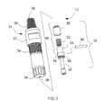
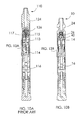
Fig. 1 is an exploded perspective view of a fluid-operated drilling tool showing a new backhead, a distributor, a piston, a wear sleeve, a chuck, and a bit and bit retaining rings. -
Fig. 2 is an enlarged exploded perspective view of the backhead and distributor assembly ofFig. 1 . -
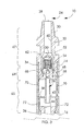
Fig. 3 is a sectioned view, in elevation, of the backhead and distributor assembly attached to the wear sleeve and showing a portion of the piston within an inner end of the backhead. -
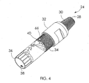
Fig. 4 is a perspective view of the backhead and distributor assembly ofFig. 1 . -
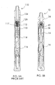
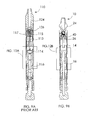
Figs. 5A and 5B are sectioned views, in elevation, of a conventional fluid-operated drilling tool and a similar tool with the new backhead ofFig. 1 , respectively. -
Fig. 6 is a perspective view of the backhead and distributor assembly similar toFig. 2 , except showing a securing member in the form of two pins. -
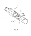
Fig. 7 is a sectioned view of the backhead and distributor assembly ofFig. 6 as assembled showing the positions of the two pins. -
Fig. 8A and Fig. 8B are sectioned views, in elevation, of a conventional fluid-operated drilling tool and a new drilling tool according to this application, respectively, showing the pistons in an impact position. -
Fig. 9A and Fig. 9B are sectioned views similar toFig. 8A and Fig. 8B , respectively, except showing the tools in a drop open position. -
Fig. 10A and 10B are sectioned views similar toFig. 8A and Fig. 8B , respectively except showing the tools with the pistons in a top position. -
Fig. 11A and Fig. 11B are enlarged views of portions ofFig. 8A and Fig. 8B , respectively. -
Fig. 12A and Fig. 12B are enlarged views of portions ofFig. 9A and 9B , respectively. -
Fig. 13A and Fig. 13B are enlarged views of portions ofFig. 10A and Fig. 10B , respectively. -
Fig. 1 is an exploded perspective view showing an embodiment of a fluid-operateddrilling tool 10. The major components of thedrilling tool 10 are a backhead anddistributor assembly 12 at a proximal end of the tool, awear sleeve 14, an axiallymovable piston 16, and at the distal or working end of the tool, achuck 18, abit 20 and bit retaining rings 22. In operation, pressurized fluid supplied to the backhead anddistributor assembly 12 is used to selectively drive thepiston 16 to reciprocatingly translate and to strike thebit 20, thus causing the bit to exert an impact force on any adjacent material to be drilled. - The
backhead assembly 12 includes abackhead 24 and a distributor orcheck valve assembly 26. Thebackhead 24 is an elongate member having an exposedproximal end 28 with aconnection 30 for attachment to a source of pressurized fluid. Thebackhead 24 also has atool receiving portion 32 shaped to receive a tool, e.g., a wrench, to assist in installing and removing the backhead. Adjacent thetool receiving portion 32 is a threadedportion 34. In the illustrated embodiment, an outer diameter of the backhead is stepped down at ashoulder 33 immediately adjacent the threadedportion 34. - The
backhead 24 has an opendistal end 36 defining one end of anaxial bore 38. Thedistributor 26 is fit within thebore 38 and is coupled to thebackhead 24, e.g., by a securing member accessible from an exterior of the backhead, such as apin 40, as described below in more detail. The distributor has an elongatedguide 42 that extends distally. - The
piston 16 has aproximal end 44 slidably received in thebore 38 and adistal end 46 slidably received within thewear sleeve 14. Thewear sleeve 14 is removably connected at its proximal end to the backhead anddistributor assembly 12, such as by the threadedportion 34. Thewear sleeve 14 extends distally in the drilling direction, and thechuck 18 is attached at its distal end. Thechuck 18 receives thebit 20, which can be held in place by the bit retaining rings 22. - Referring to
Fig. 2 , thedistributor 26 has acheck valve 48 with a cap-shaped sealingmember 50, a biasingmember 52 andstationary member 54 from which theelongated guide 42 extends. Thestationary member 54 has atransverse bore 56 sized to receive thepin 40 and acircumferential groove 58 for a seal. - Referring to
Fig. 3 , theaxial bore 38 has aninlet bore segment 60 extending from theproximal end 28 of thebackhead 24 that widens into achamber 62. At its distal end, thechamber 62 narrows slightly into a necked-down portion defining a checkvalve receiving area 64 that receives thestationary member 54 of thedistributor 26 as shown. At the distal end of the checkvalve receiving area 64, thebore 38 is widest and the inner surface thereof defines acylinder portion 65 within which the proximal end of thepiston 16 is slidably received. Thestationary member 54 and a seal in thegroove 58 seal off thechamber 62 from thebore 38 when the valve is in normal operation. Thus, the checkvalve receiving area 64 separates thecylinder portion 65 from aninlet area 67 extending proximally of the checkvalve receiving area 64. - The
backhead 24 has at least one throughpassage 68 which connects thechamber 60 with an axially extendingannular space 70 in thewear tube 14. In a representative embodiment as shown inFigs. 3 and4 , there are multiple circumferentially-spaced fluid throughpassages 68. Adjacent thedistal end 36, thebackhead 24 has circumferentially spacedexternal grooves 72 that also serve as flow passages between the backhead and the surroundingwear sleeve 14. As best shown inFig. 3 , thebackhead 24 and wearsleeve 14 can be shaped such that the backhead has a close fit with the wear sleeve adjacent thedistal end 36, and is spaced from the wear sleeve along at least a segment of its length in the area of theannular space 70. - In one embodiment, as best shown in
Fig. 4 , the securing member is thepin 40 and thebackhead 24 has atransverse opening 66 sized to receive thepin 40. In theFig. 4 embodiment, unthreading thebackhead 24 exposes thepin 40 and thus allows thedistributor 26 to be removed from thebackhead 24. Of course, it is also possible to use a securing member of a type other than a pin. - In another embodiment, as best shown in
Fig. 6 , the securing member is a pair ofpins openings openings Fig. 7 , thepins groove 69 formed in the backhead. Of course, it would be possible to use additional pins or elements, and/or to use elements extending only partially through the backhead. -
Fig. 5A shows a conventional fluid-operateddrilling tool 110 having abackhead 124, aninner cylinder component 113 separate from thebackhead 124 and a distributor (or check valve assembly) 126 coupled to thewear sleeve 114. Thebackhead 124 is connected to thewear sleeve 114 by a threaded connection. Because theinner cylinder component 113 is also a separate component, it must also be coupled to thewear sleeve 114. As shown inFig. 5A , theinner cylinder component 113 is coupled to thewear sleeve 114 by retainingmembers 115 that expand to fit within acircumferential groove 117 formed in the wear sleeve at a position spaced from its proximal end. - With the
conventional tool 110, removing thedistributor 126 can be very difficult. Thedistributor 126 might need to be removed in order to repair or service it, to use it in anew wear sleeve 114, to replace or service thepiston 116, etc. To remove thedistributor 126, thebackhead 124 is unscrewed from thewear sleeve 114. A tool is then inserted into thewear sleeve 114 in an effort to contact the retainingmembers 115 and disengage them from thegroove 117. This operation is often very difficult to execute, especially in conditions encountered in the field. With small versions of thetool 110, a user can sometimes succeed in disengaging thedistributor 126 by inverting thewear sleeve 114 and hitting its proximal end against a hard surface. With larger versions of thetool 110, it is not possible to maneuver the wear sleeve in this way. - By comparison, the
tool 10 with the new backhead and integrated cylinder as shown inFig. 5B allows comparatively easy disassembly. Thebackhead assembly 12 is unscrewed from thewear sleeve 14, and thedistributor 26 can be removed from thebackhead 24 by removing the securing member, e.g., removing thepin 40. With thebackhead assembly 12 unscrewed from thewear sleeve 14, thepiston 16 is easily accessible and can be slid out of thewear sleeve 14. - The
wear sleeve 14 does not require any complicated machining to form a groove or other undercut retaining feature similar to thegroove 117, and thus is simpler and cheaper to produce. Without these features, the walls of the wear sleeve can be made thinner. Stated differently, for a given external diameter, such as for the 4-inch (about 10 cm)tools wear sleeve 14 can accommodate apiston 16 having an area at least about 5% greater than thepiston 116, as is described below in greater detail. - The
new backhead assembly 12 with theintegrated distributor 26 conserves operating length in the axial direction. Thus, thetool 10 can have a shorter length than theconventional tool 110 with the same or comparable operating capabilities. As a result, thetool 10 can save costs and is easier to handle. - In the following description, a comparison of the flow passageways and piston areas between the
conventional drilling tool 110 and thedrilling tool 10 is described. -
Fig. 8A and Fig. 8B are section views in elevation showing the conventional drilling tool and a drilling tool according to an embodiment of this application, respectively, in the impact position, i.e., when the piston has contacted the bit, which in turn exerts an impact on any material with which the bit is in contact.Figs. 9A and 9B are similar toFigs. 8A and 8B , but shown the respective drilling tools in a drop open position, when the tools have been brought to rest, such as, e.g., if a void is encountered while drilling.Figs. 10A and 10B are similar toFigs. 8A and 8B , but show the respective drilling tools in a position when the piston is at the top of its stroke, i.e., withdrawn in the distal direction. -
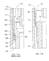
Fig. 11A is an enlarged section view of a portion of theconventional drilling tool 110 shown inFig. 8A (i.e., in the impact position). As seen inFig. 11A , the intake of compressed operating fluid, which occurs at one or more times during a complete operating cycle, forces the fluid to follow aflow path 180 through two substantial changes in direction. As a result, the flow's velocity is decreased and thus the time required to complete the intake is lengthened. Specifically, theintake flow path 180 has anupper segment 182 beginning in thepassageway 192 between thewear sleeve 114 and theinner cylinder component 113. Where the flow leaves thepassageway 192, theflow path 180 turns abruptly inward at a firstsharp bend 186 and continues through theaperture 194 formed in a wall of theinner cylinder 113 along anintermediate segment 184. After traveling through theaperture 194, the flow encounters the solid wall of thepiston 116, so it makes another abrupt turn at a secondsharp bend 188. Theflow path 180 then continues in a downward direction along alower segment 190 in the direction of the arrow, which travels through aninner passageway 196 formed between an inner side of theinner cylinder 113 and the outer wall of thepiston 116, before leading into aregion 198 between thepiston 116 and thewear sleeve 114. - As shown in the drawing, the intake flow must travel through two substantial bends, each of which is approximately 90 degrees along the mean flow path. As a result, velocity decreases substantially and momentum and energy are lost. Although only a single
intake flow path 180 is represented for the portion of theconventional drilling tool 110 shown inFig. 11A , it should be noted that the conventional drilling tool has four equally spacedapertures 194, and thus there are four corresponding intake flows following correspondingintake flow paths 180. -
Fig. 11B is an enlarged view of a portion of thedrilling tool 10 according to this application, taken fromFig. 8B . As seen inFig. 11B , a comparableintake flow path 80 begins in the area of one of thegrooves 72 formed in thebackhead 24 and extends in a generally straight direction downward into aregion 96 between thepiston 16 and thewear sleeve 14. - The
flow path 80 as shown inFig. 11B , which corresponds to one of thegrooves 72 appears as a single path. In fact, theflow path 80 comprises the area of all of thegrooves 72 positioned around the entire circumference of thebackhead 24. Thus, themany grooves 72 of thedrilling tool 10 comprise a greater flow area than the fourapertures 194 in theconventional drilling tool 10. - Because the
flow path 80 is substantially free of sharp bends, loss of energy due to friction and decreases in velocity are reduced. Stated differently, theflow path 80 is much more energy efficient than theflow path 180 in theconventional drilling tool 110. In addition, theflow path 80 does not force the intake flow through any apertures or other bounded openings at sharp angles to the flow's primary direction. Also, the intake flow passes along walls (e.g., the outer periphery of the backhead 24) rather than through them (compare theconventional drilling tool 110, where the intake flow must pass through the inner cylinder 113). -
Fig. 12A is an enlarged section view of a portion of theconventional drilling tool 110 shown inFig. 9A (drop open position). Similarly,Fig. 12B is an enlarged view of a portion of thedrilling tool 10 according to this application, taken fromFig. 9B . -
Fig. 12A shows the piston area, AC, against which the pressurized operating fluid can act to move thepiston 116 in theconventional drilling tool 110. As shown inFig. 12B , the piston area AN in thedrilling tool 10 is greater than the piston area AC. - The available piston area includes the area of the upper surface of the piston and other areas exposed to the pressure, which equate to the annular area bounded on the outside by the piston's outer diameter and on the inside by the piston's axial bore. In some embodiments, the area AN exceeds the area Ac by about 5% to even about 25%. As an example, a about 10 cm (4-inch) diameter drilling tool may have a piston area AC of about about 53.94 cm2 (8.36 in2), whereas a about 10 cm (4-inch) diameter drilling tool according to an embodiment of this application has a piston area AN of about about 58.06 cm2 (9.13 in2), which is about 9.3% greater.
- The greater available piston area in the
drilling tool 10 allows the pressure acting on thepiston 16 to move the piston more quickly, thus increasing the power of the piston. - In the
drilling tool 10, when bit is positioned in the drop open position, as best seen inFig. 9B , the upper end of the piston is spaced away any surrounding surfaces. Because the entire circumferential area around thepiston 16 is open, this area fills with pressurized fluid quickly and thus pushes thepiston 16 downward to the full drop open position shown inFig. 9B faster. - By way of contrast, in the
drilling tool 110, thepiston 116 remains in contact with the surroundinginner cylinder 113. Thus, pressurized air tending to push thepiston 116 downward into the full drop open position shown inFig. 9A must be forced through the smaller area of the fourapertures 194. - In addition, as best seen by comparing
Fig. 9A and Fig. 9B , because thedrilling tool 10 is designed to function without the upper end of thepiston 16 being in contact with any surrounding structure in the drop open position, thepiston 16 can be made shorter in length than thepiston 116 of theconventional drilling tool 110 of a comparable overall outer diameter. -
Fig. 13A is an enlarged section view of a portion of theconventional drilling tool 110 shown inFig. 10A , where thepiston 116 is in its uppermost position and just prior to commencing a downward stroke. As shown inFig. 13A , the intake flow follows thesame flow path 180 that includes the twosharp bends Fig. 11A . - In addition, as the intake flow travels through the
aperture 194 and then flows in a downward direction along thelower segment 190 within theinner passageway 196, it encounters a volume of pressurized air in an area 121 (Fig. 10A ) surrounding thepiston 116. At the position shown inFig. 13A , thepiston 116 has just moved upward (i.e., from the position shown inFig. 11A ) such that its upper end is no longer sealed against theinner cylinder 113, thereby creating an upper opening 119 (i.e., the space between the outer surface of the piston and the inner relieved surface of theinner cylinder 113, which has a larger diameter) in thepassageway 196. Theopening 119 thus connects the lower portion of thepassageway 196 with the space above the upper surface of thepiston 116, which is at a lower pressure. Once theopening 119 is established, the higher pressure fluid in thearea 121 seeks to expand, thus exerting an upward pressure in the direction of theopening 119. At the same time, however, a portion of the intake flow from theaperture 194 is seeking to flow downwardly through the passageway 196 (a portion of the intake flow also flows upwardly as shown). Thus, the intake flow, particularly along thelower segment 190, must overcome the oppositely directedpressure 210 from thearea 121. As shown by the arrows, this confrontation takes place in a highly constricted area. Because of this confrontation, the intake flow along theintake flow path 180 experiences greater energy losses and its resulting velocity is lower. -
Fig. 13B is an enlarged section view of a portion of thedrilling tool 10 according to this application, taken fromFig. 10A . In contrast to theconventional drilling tool 110, theintake flow path 92 and the fillingflow path 200 are arranged for increased efficiency. First, the number of sharp bends in the intake flow path is reduced (in the case of theflow path 92, there are no sharp bends). Second, theintake flow path 92 and the fillingflow path 200 are configured so that they are spaced apart from each other rather than directed along nearly the same axis. Third, the area where the intake flow and the filling flow first encounter each other (i.e., where they are first no longer separated from each other by a wall), has a much larger cross section to promote separation between the flows. - Comparing
Fig. 13B to Fig. 13A , it can be seen that the cross-sectional area of theinner passage way 96 in the area where theflows inner passageway 196 adjacent theaperture 194. In addition, as described above, there only four such flow path areas as shown inFig. 13A , whereas there are a much greater number of the flow paths shown inFig. 13B . Therefore, compared to the conventional drilling tool, theflow 92 in thedrilling tool 10 flows with much less energy loss due to conflict with theflow 200, and vice versa. - In view of the many possible embodiments to which the principles of the disclosed invention may be applied, it should be recognized that the illustrated embodiments are only preferred examples and should not be taken as limiting in scope. Rather, the scope is defined by the following claims.
Claims (15)
- A portion of a drill assembly operated by a supply of compressed fluid, comprising:a backhead (24) having a proximal end (28) connectible to the supply, an axial bore (38) and an open distal end (36), the backhead (24) having passages (68) extending between the axial bore (38) and outer surface of the backhead (24);a hollow elongate wear sleeve (14) having a proximal end to which the backhead (24) is coupled and into which the distal end (36) of the backhead (24) is received; anda piston (16) housed by the wear sleeve (14) and having a proximal end (44), the piston (16) being slidably movable along the wear sleeve (14) in response to compressed fluid conveyed through the backhead (24),wherein an intake flow path (80, 92) for an intake flow of compressed fluid in the drilling tool extends in a distal direction from the axial bore (38), through the passages (68) in the backhead (24), through a space (70) between the backhead (24) and the wear sleeve (14) and into an area (96) between the piston (16) and wear sleeve (14) and into contact with the piston (16),characterized in that the distal end (36) of the backhead (24) has defined therein an integrated cylinder portion (65), with the proximal end (44) of the piston (16) being shaped to fit within the integrated cylinder portion (65) of the backhead (24), and being slidably movable .along the integrated cylinder portion (65) in response to the compressed fluid.
- The portion of a drill assembly of claim 1, wherein the intake flow path (80, 92) does not extend through any apertures forcing the intake flow in a radially inward direction.
- The portion of a drill assembly of claim 1 , wherein the intake flow path (80, 92) does not require the intake flow to pass inwardly through any openings defined in a sidewall of the backhead (24).
- The portion of a drill assembly of claim 1, further comprising a distributor (26) positioned at least partially within the axial bore (38) between the proximal end (28) and the distal end (36), the distributor (26) being removably secured to the backhead (24) by a securing member (40; 41) accessible from an exterior surface of the backhead (24), the distributor (26) including a check valve (48) that is opened to allow the intake flow from the supply.
- The portion of a drill assembly of claim 1, further comprising a chuck (18) coupled to a distal end of the wear sleeve (14) and capable of receiving a drill bit (20) and being movable in response to contact from the piston (16).
- The portion of a drill assembly of claim 4, wherein the securing member comprises a laterally extending pin (40) inserted through at least one opening (66) in the backhead (24).
- The portion of a drill assembly of claim 4, wherein the securing member comprises at least two laterally extending pins (41), each of the pins (41) being inserted through one of a corresponding number of spaced-apart openings (67) in the backhead (24).
- The portion of a drill assembly of claim 4, wherein the distributor (26) further comprises a check valve sealing member (50), a biasing member (52) that biases the sealing member (50) to a closed position and a distally extending guide portion (42).
- The portion of a drill assembly of claim 1 wherein when the drill assembly is in a drop open position, a proximal end (44) of the piston (16) is spaced apart from the integrated cylinder portion (65) in the distal direction and an open annular space (96) is defined between a proximal end (44) of the piston (16) and the wear sleeve (14).
- The portion of the drill assembly of claim 9, wherein the piston (16) has an available piston area (An) subject to pressure tending to move the piston (16) in a distal direction that is about 5% to about 25% greater than the available piston area (Ac) of a conventional drill assembly of the same outer diameter.
- The portion of the drill assembly of claim 10, wherein the piston has an available piston area (An) subject to pressure tending to move the piston (16) in a distal direction that is about 8% to about 10% greater than the available piston area (Ac) of a conventional drill assembly of the same outer diameter.
- The portion of the drill assembly of claim 10, wherein the piston (16) has an available piston area (An) subject to pressure tending to move the piston (16) in a distal direction that is at least about 9% greater than the available piston area (Ac) of a conventional drill assembly of the same outer diameter.
- The portion of a drill assembly of claim 1 wherein when the drill assembly is in a drop open position, a proximal end (44) of the piston (16) is spaced apart from the cylinder portion (65) and the wear sleeve (14).
- The portion of a drill assembly of claim 1 wherein a filling flow path (200) extends in the proximal direction from the area (96) between the piston (16) and the wear sleeve (14), along the piston (16) and between the piston (16) and the backhead (24) into a space proximal of the proximal end (44) of the piston (16), and wherein a separation is maintained between the intake flow path (92) and the filling flow path (200) in the area between the piston (16) and the wear sleeve (14).
- The portion of the drill assembly of claim 14, wherein the distal end (36) of the backhead (24) has a circumferential wall configured to guide the filling flow (200) flowing in the proximal direction along an inner surface of the wall and configured to guide the intake flow (80, 92) flowing in the distal direction along an outer surface of the wall, the intake flow (80, 92) and the filling flow (200) being separated from each other by the wall.
Applications Claiming Priority (2)
| Application Number | Priority Date | Filing Date | Title |
|---|---|---|---|
| US73386005P | 2005-11-03 | 2005-11-03 | |
| PCT/US2006/042740 WO2007056035A1 (en) | 2005-11-03 | 2006-10-31 | Backhead and drill assembly with backhead |
Publications (3)
| Publication Number | Publication Date |
|---|---|
| EP1943407A1 EP1943407A1 (en) | 2008-07-16 |
| EP1943407A4 EP1943407A4 (en) | 2012-01-04 |
| EP1943407B1 true EP1943407B1 (en) | 2015-04-15 |
Family
ID=38023578
Family Applications (1)
| Application Number | Title | Priority Date | Filing Date |
|---|---|---|---|
| EP06827334.1A Active EP1943407B1 (en) | 2005-11-03 | 2006-10-31 | Backhead and drill assembly with backhead |
Country Status (7)
| Country | Link |
|---|---|
| US (2) | US7617889B2 (en) |
| EP (1) | EP1943407B1 (en) |
| KR (1) | KR101011433B1 (en) |
| AU (1) | AU2006311987B2 (en) |
| CA (1) | CA2627488C (en) |
| ES (1) | ES2536070T3 (en) |
| WO (1) | WO2007056035A1 (en) |
Families Citing this family (13)
| Publication number | Priority date | Publication date | Assignee | Title |
|---|---|---|---|---|
| CA2627488C (en) * | 2005-11-03 | 2012-10-23 | Rockmore International, Inc. | Backhead and drill assembly with backhead |
| US8596398B2 (en) | 2007-05-16 | 2013-12-03 | Polaris Industries Inc. | All terrain vehicle |
| SK932007A3 (en) * | 2007-07-09 | 2009-02-05 | Konek, S. R. O. | Hydraulic scarified hammer |
| RU2443845C1 (en) * | 2008-01-07 | 2012-02-27 | Сук Син ИН | Vibration hammer |
| AU2009231791B2 (en) * | 2008-03-31 | 2012-04-05 | Center Rock Inc. | Down-the-hole drill drive coupling |
| US8302707B2 (en) * | 2009-01-28 | 2012-11-06 | Center Rock Inc. | Down-the-hole drill reverse exhaust system |
| US8800690B2 (en) * | 2008-03-31 | 2014-08-12 | Center Rock Inc. | Down-the-hole drill hammer having a reverse exhaust system and segmented chuck assembly |
| US8622152B2 (en) | 2009-01-28 | 2014-01-07 | Center Rock Inc. | Down-the-hole drill hammer having a sliding exhaust check valve |
| DE102009023910A1 (en) * | 2009-03-03 | 2010-09-16 | Tracto-Technik Gmbh & Co. Kg | An earth boring |
| US9016403B2 (en) * | 2012-09-14 | 2015-04-28 | Drillco Tools S.A. | Pressurized fluid flow system having multiple work chambers for a down-the-hole drill hammer and normal and reverse circulation hammers thereof |
| US10100578B2 (en) * | 2013-06-10 | 2018-10-16 | Center Rock, Inc. | Pressure control check valve for a down-the-hole drill hammer |
| CL2017001018A1 (en) * | 2017-04-25 | 2017-12-15 | Drillco Tools S A | Bottom Hammer Head Assembly |
| CN111411899B (en) * | 2020-05-28 | 2023-05-26 | 西南石油大学 | PDC drill bit with self-impact capability |
Family Cites Families (36)
| Publication number | Priority date | Publication date | Assignee | Title |
|---|---|---|---|---|
| US3704756A (en) * | 1971-07-19 | 1972-12-05 | Boyles Ind Ltd | Apparatus for lowering and retrieving a core barrel |
| DE2750603A1 (en) | 1977-11-14 | 1979-05-17 | Inst Gornogo Dela Sibirskogo O | STRIKING |
| EP0040026A1 (en) * | 1980-05-09 | 1981-11-18 | Halifax Tool Company Limited | Free piston machines |
| ZA863192B (en) * | 1986-04-29 | 1986-12-30 | Abraham Gien | Improvement in valveless pneumatic hammer |
| AU542647B2 (en) | 1981-01-22 | 1985-02-28 | Dresser Industries Inc. | Percussive down the hole drill |
| US4819739A (en) * | 1984-08-31 | 1989-04-11 | Dresser Industries, Inc. | Fluid actuated rock drill hammer |
| US4828048A (en) * | 1986-11-10 | 1989-05-09 | Mayer James R | Hydraulic Percussion tool |
| US4819746A (en) | 1987-01-13 | 1989-04-11 | Minroc Technical Promotions Ltd. | Reverse circulation down-the-hole hammer drill and bit therefor |
| US4878550A (en) | 1988-07-15 | 1989-11-07 | Sandvik Rock Tools, Inc. | Pilot-valve-controlled percussion drilling tool |
| US4923018A (en) | 1989-03-02 | 1990-05-08 | Sandvik Rock Tools, Inc. | Percussion drill |
| US5325926A (en) * | 1993-02-05 | 1994-07-05 | Ingersoll-Rand Company | Reversible casing for a down-the-hole percussive apparatus |
| US5301761A (en) | 1993-03-09 | 1994-04-12 | Ingersoll-Rand Company | Pressure reversing valve for a fluid-actuated, percussive drilling apparatus |
| US5685380A (en) | 1995-01-06 | 1997-11-11 | Minroc Technical Promotions Limited | Reverse circulation down-the-hole drill |
| IE80718B1 (en) | 1995-01-06 | 1998-12-30 | Minroc Techn Promotions Ltd | A reverse circulation down-the-hole drill |
| US5511628A (en) | 1995-01-20 | 1996-04-30 | Holte; Ardis L. | Pneumatic drill with central evacuation outlet |
| RU2090730C1 (en) | 1995-05-11 | 1997-09-20 | Институт горного дела СО РАН | Downhole pneumatic percussion mechanism |
| US5566771A (en) * | 1995-08-30 | 1996-10-22 | Ingersoll-Rand Company | Reversible casing for a self-lubricating, fluid-actuated, percussive down-the-hole drill |
| US5562170A (en) * | 1995-08-30 | 1996-10-08 | Ingersoll-Rand Company | Self-lubricating, fluid-actuated, percussive down-the-hole drill |
| US5682957A (en) | 1995-12-21 | 1997-11-04 | Ingersoll-Rand Company | Water separator for a down hole drill |
| US5803187A (en) * | 1996-08-23 | 1998-09-08 | Javins; Brooks H. | Rotary-percussion drill apparatus and method |
| US5944117A (en) * | 1997-05-07 | 1999-08-31 | Eastern Driller's Manufacturing Co., Inc. | Fluid actuated impact tool |
| WO1999064711A2 (en) * | 1998-06-12 | 1999-12-16 | Ingersoll-Rand Company | Improved backhead and check valve for down-hole drills |
| US6062322A (en) * | 1998-06-15 | 2000-05-16 | Sandvik Ab | Precussive down-the-hole rock drilling hammer |
| IES980988A2 (en) | 1998-11-27 | 1999-09-08 | Minroc Techn Promotions Ltd | Segmented ring mounting for a fluid-operated percussion drill tool |
| EP1165929A1 (en) | 1999-03-03 | 2002-01-02 | Earth Tool Company L.L.C. | Method and apparatus for directional boring |
| IES20000221A2 (en) | 2000-03-22 | 2001-10-03 | Minroc Techn Promotions Ltd | Down-the-hole hammer with variable pressure chamber |
| AUPQ717100A0 (en) | 2000-04-28 | 2000-05-18 | Rear, Ian Graeme | Down hole hammer having a top sub |
| US6454026B1 (en) * | 2000-09-08 | 2002-09-24 | Sandvik Ab | Percussive down-the-hole hammer for rock drilling, a top sub used therein and a method for adjusting air pressure |
| US6502650B1 (en) * | 2000-11-15 | 2003-01-07 | Sandvik Ab | Percussive down-the-hole hammer for rock drilling, and a drill bit used therein |
| WO2003031761A1 (en) * | 2001-10-10 | 2003-04-17 | Reginald Frederick Taylor | Down-the-hole drill hammer |
| CN100458096C (en) * | 2001-11-14 | 2009-02-04 | 阿特拉斯﹒科普科﹒西科罗克有限责任公司 | Fluid distributor device for down-hole-drills |
| IES20020794A2 (en) | 2002-10-04 | 2003-02-19 | Minroc Techn Promotions Ltd | A down-the-hole hammer |
| US7198120B2 (en) | 2003-03-25 | 2007-04-03 | Bernard Lionel Gien | Down-the-hole drill assembly |
| US6799641B1 (en) | 2003-06-20 | 2004-10-05 | Atlas Copco Ab | Percussive drill with adjustable flow control |
| IES20050495A2 (en) * | 2005-07-20 | 2006-11-01 | Minroc Techn Promotions Ltd | A drill bit assembly for fluid-operated percussion drill tools |
| CA2627488C (en) * | 2005-11-03 | 2012-10-23 | Rockmore International, Inc. | Backhead and drill assembly with backhead |
-
2006
- 2006-10-31 CA CA2627488A patent/CA2627488C/en active Active
- 2006-10-31 AU AU2006311987A patent/AU2006311987B2/en active Active
- 2006-10-31 ES ES06827334.1T patent/ES2536070T3/en active Active
- 2006-10-31 US US11/817,292 patent/US7617889B2/en active Active
- 2006-10-31 WO PCT/US2006/042740 patent/WO2007056035A1/en active Application Filing
- 2006-10-31 EP EP06827334.1A patent/EP1943407B1/en active Active
- 2006-10-31 KR KR1020087013202A patent/KR101011433B1/en active IP Right Grant
-
2009
- 2009-06-29 US US12/494,126 patent/US8006784B2/en active Active
Also Published As
| Publication number | Publication date |
|---|---|
| CA2627488C (en) | 2012-10-23 |
| ES2536070T3 (en) | 2015-05-20 |
| KR101011433B1 (en) | 2011-01-28 |
| US8006784B2 (en) | 2011-08-30 |
| KR20080088586A (en) | 2008-10-02 |
| EP1943407A4 (en) | 2012-01-04 |
| EP1943407A1 (en) | 2008-07-16 |
| AU2006311987B2 (en) | 2011-03-10 |
| AU2006311987A1 (en) | 2007-05-18 |
| WO2007056035A1 (en) | 2007-05-18 |
| US20080156540A1 (en) | 2008-07-03 |
| CA2627488A1 (en) | 2007-05-18 |
| US20090260889A1 (en) | 2009-10-22 |
| US7617889B2 (en) | 2009-11-17 |
Similar Documents
| Publication | Publication Date | Title |
|---|---|---|
| EP1943407B1 (en) | Backhead and drill assembly with backhead | |
| EP2627850B1 (en) | A down-the-hole hammer | |
| CA2654461C (en) | Device for channeling solids and fluids within a reverse circulation drill | |
| KR101412907B1 (en) | Down-the-hole hammer drill | |
| US20110209919A1 (en) | Pressurized fluid flow system for a normal circulation hammer and hammer thereof | |
| EP1757769B1 (en) | Percussion drill bit | |
| US20080078584A1 (en) | Bit assembly for down-hole drills | |
| US10316586B1 (en) | Pressurized fluid flow system for a DTH hammer and normal circulation hammer thereof | |
| US8973681B2 (en) | Pressurized fluid flow system for a reverse circulation down-the-hole hammer and hammer thereof | |
| EP3553270B1 (en) | Pressurised fluid flow system for a dth hammer and normal circulation hammer based on same | |
| US6550554B2 (en) | Rock drill | |
| RU2280748C1 (en) | Bottomhole drilling string assembly for inclined and horizontal well drilling with the use of downhole screw motor | |
| US11933143B1 (en) | Pressurized fluid flow system for percussive mechanisms | |
| AU2013206483B2 (en) | Pressurized fluid flow system for a reverse circulation down-the-hole hammer and hammer thereof | |
| WO2023128844A1 (en) | Down-the-hole hammer | |
| IES85798Y1 (en) | A down-the-hole hammer | |
| IE20100666U1 (en) | A down-the-hole hammer | |
| IE20050621U1 (en) | A percussion hammer for enlarging drilled holes |
Legal Events
| Date | Code | Title | Description |
|---|---|---|---|
| PUAI | Public reference made under article 153(3) epc to a published international application that has entered the european phase |
Free format text: ORIGINAL CODE: 0009012 |
|
| 17P | Request for examination filed |
Effective date: 20080419 |
|
| AK | Designated contracting states |
Kind code of ref document: A1 Designated state(s): AT BE BG CH CY CZ DE DK EE ES FI FR GB GR HU IE IS IT LI LT LU LV MC NL PL PT RO SE SI SK TR |
|
| A4 | Supplementary search report drawn up and despatched |
Effective date: 20111201 |
|
| RIC1 | Information provided on ipc code assigned before grant |
Ipc: E21B 4/14 20060101AFI20111125BHEP Ipc: E21B 1/38 20060101ALI20111125BHEP |
|
| DAX | Request for extension of the european patent (deleted) | ||
| GRAP | Despatch of communication of intention to grant a patent |
Free format text: ORIGINAL CODE: EPIDOSNIGR1 |
|
| INTG | Intention to grant announced |
Effective date: 20141024 |
|
| GRAS | Grant fee paid |
Free format text: ORIGINAL CODE: EPIDOSNIGR3 |
|
| GRAA | (expected) grant |
Free format text: ORIGINAL CODE: 0009210 |
|
| AK | Designated contracting states |
Kind code of ref document: B1 Designated state(s): AT BE BG CH CY CZ DE DK EE ES FI FR GB GR HU IE IS IT LI LT LU LV MC NL PL PT RO SE SI SK TR |
|
| REG | Reference to a national code |
Ref country code: GB Ref legal event code: FG4D Ref country code: CH Ref legal event code: EP |
|
| REG | Reference to a national code |
Ref country code: IE Ref legal event code: FG4D |
|
| REG | Reference to a national code |
Ref country code: AT Ref legal event code: REF Ref document number: 722105 Country of ref document: AT Kind code of ref document: T Effective date: 20150515 |
|
| REG | Reference to a national code |
Ref country code: ES Ref legal event code: FG2A Ref document number: 2536070 Country of ref document: ES Kind code of ref document: T3 Effective date: 20150520 |
|
| REG | Reference to a national code |
Ref country code: DE Ref legal event code: R096 Ref document number: 602006045163 Country of ref document: DE Effective date: 20150528 |
|
| REG | Reference to a national code |
Ref country code: SE Ref legal event code: TRGR |
|
| REG | Reference to a national code |
Ref country code: NL Ref legal event code: VDEP Effective date: 20150415 |
|
| REG | Reference to a national code |
Ref country code: LT Ref legal event code: MG4D |
|
| PG25 | Lapsed in a contracting state [announced via postgrant information from national office to epo] |
Ref country code: NL Free format text: LAPSE BECAUSE OF FAILURE TO SUBMIT A TRANSLATION OF THE DESCRIPTION OR TO PAY THE FEE WITHIN THE PRESCRIBED TIME-LIMIT Effective date: 20150415 |
|
| PG25 | Lapsed in a contracting state [announced via postgrant information from national office to epo] |
Ref country code: PT Free format text: LAPSE BECAUSE OF FAILURE TO SUBMIT A TRANSLATION OF THE DESCRIPTION OR TO PAY THE FEE WITHIN THE PRESCRIBED TIME-LIMIT Effective date: 20150817 Ref country code: LT Free format text: LAPSE BECAUSE OF FAILURE TO SUBMIT A TRANSLATION OF THE DESCRIPTION OR TO PAY THE FEE WITHIN THE PRESCRIBED TIME-LIMIT Effective date: 20150415 |
|
| PG25 | Lapsed in a contracting state [announced via postgrant information from national office to epo] |
Ref country code: GR Free format text: LAPSE BECAUSE OF FAILURE TO SUBMIT A TRANSLATION OF THE DESCRIPTION OR TO PAY THE FEE WITHIN THE PRESCRIBED TIME-LIMIT Effective date: 20150716 Ref country code: LV Free format text: LAPSE BECAUSE OF FAILURE TO SUBMIT A TRANSLATION OF THE DESCRIPTION OR TO PAY THE FEE WITHIN THE PRESCRIBED TIME-LIMIT Effective date: 20150415 Ref country code: IS Free format text: LAPSE BECAUSE OF FAILURE TO SUBMIT A TRANSLATION OF THE DESCRIPTION OR TO PAY THE FEE WITHIN THE PRESCRIBED TIME-LIMIT Effective date: 20150815 |
|
| REG | Reference to a national code |
Ref country code: DE Ref legal event code: R097 Ref document number: 602006045163 Country of ref document: DE |
|
| PG25 | Lapsed in a contracting state [announced via postgrant information from national office to epo] |
Ref country code: DK Free format text: LAPSE BECAUSE OF FAILURE TO SUBMIT A TRANSLATION OF THE DESCRIPTION OR TO PAY THE FEE WITHIN THE PRESCRIBED TIME-LIMIT Effective date: 20150415 Ref country code: EE Free format text: LAPSE BECAUSE OF FAILURE TO SUBMIT A TRANSLATION OF THE DESCRIPTION OR TO PAY THE FEE WITHIN THE PRESCRIBED TIME-LIMIT Effective date: 20150415 |
|
| PLBE | No opposition filed within time limit |
Free format text: ORIGINAL CODE: 0009261 |
|
| STAA | Information on the status of an ep patent application or granted ep patent |
Free format text: STATUS: NO OPPOSITION FILED WITHIN TIME LIMIT |
|
| PG25 | Lapsed in a contracting state [announced via postgrant information from national office to epo] |
Ref country code: PL Free format text: LAPSE BECAUSE OF FAILURE TO SUBMIT A TRANSLATION OF THE DESCRIPTION OR TO PAY THE FEE WITHIN THE PRESCRIBED TIME-LIMIT Effective date: 20150415 Ref country code: RO Free format text: LAPSE BECAUSE OF NON-PAYMENT OF DUE FEES Effective date: 20150415 Ref country code: CZ Free format text: LAPSE BECAUSE OF FAILURE TO SUBMIT A TRANSLATION OF THE DESCRIPTION OR TO PAY THE FEE WITHIN THE PRESCRIBED TIME-LIMIT Effective date: 20150415 Ref country code: SK Free format text: LAPSE BECAUSE OF FAILURE TO SUBMIT A TRANSLATION OF THE DESCRIPTION OR TO PAY THE FEE WITHIN THE PRESCRIBED TIME-LIMIT Effective date: 20150415 |
|
| 26N | No opposition filed |
Effective date: 20160118 |
|
| PG25 | Lapsed in a contracting state [announced via postgrant information from national office to epo] |
Ref country code: LU Free format text: LAPSE BECAUSE OF FAILURE TO SUBMIT A TRANSLATION OF THE DESCRIPTION OR TO PAY THE FEE WITHIN THE PRESCRIBED TIME-LIMIT Effective date: 20151031 Ref country code: SI Free format text: LAPSE BECAUSE OF FAILURE TO SUBMIT A TRANSLATION OF THE DESCRIPTION OR TO PAY THE FEE WITHIN THE PRESCRIBED TIME-LIMIT Effective date: 20150415 |
|
| REG | Reference to a national code |
Ref country code: CH Ref legal event code: PL |
|
| PG25 | Lapsed in a contracting state [announced via postgrant information from national office to epo] |
Ref country code: MC Free format text: LAPSE BECAUSE OF FAILURE TO SUBMIT A TRANSLATION OF THE DESCRIPTION OR TO PAY THE FEE WITHIN THE PRESCRIBED TIME-LIMIT Effective date: 20150415 |
|
| PG25 | Lapsed in a contracting state [announced via postgrant information from national office to epo] |
Ref country code: CH Free format text: LAPSE BECAUSE OF NON-PAYMENT OF DUE FEES Effective date: 20151031 Ref country code: LI Free format text: LAPSE BECAUSE OF NON-PAYMENT OF DUE FEES Effective date: 20151031 |
|
| PG25 | Lapsed in a contracting state [announced via postgrant information from national office to epo] |
Ref country code: BE Free format text: LAPSE BECAUSE OF FAILURE TO SUBMIT A TRANSLATION OF THE DESCRIPTION OR TO PAY THE FEE WITHIN THE PRESCRIBED TIME-LIMIT Effective date: 20150415 |
|
| REG | Reference to a national code |
Ref country code: FR Ref legal event code: PLFP Year of fee payment: 11 |
|
| REG | Reference to a national code |
Ref country code: AT Ref legal event code: UEP Ref document number: 722105 Country of ref document: AT Kind code of ref document: T Effective date: 20150415 |
|
| PG25 | Lapsed in a contracting state [announced via postgrant information from national office to epo] |
Ref country code: BG Free format text: LAPSE BECAUSE OF FAILURE TO SUBMIT A TRANSLATION OF THE DESCRIPTION OR TO PAY THE FEE WITHIN THE PRESCRIBED TIME-LIMIT Effective date: 20150415 Ref country code: HU Free format text: LAPSE BECAUSE OF FAILURE TO SUBMIT A TRANSLATION OF THE DESCRIPTION OR TO PAY THE FEE WITHIN THE PRESCRIBED TIME-LIMIT; INVALID AB INITIO Effective date: 20061031 |
|
| PG25 | Lapsed in a contracting state [announced via postgrant information from national office to epo] |
Ref country code: CY Free format text: LAPSE BECAUSE OF FAILURE TO SUBMIT A TRANSLATION OF THE DESCRIPTION OR TO PAY THE FEE WITHIN THE PRESCRIBED TIME-LIMIT Effective date: 20150415 |
|
| PG25 | Lapsed in a contracting state [announced via postgrant information from national office to epo] |
Ref country code: TR Free format text: LAPSE BECAUSE OF FAILURE TO SUBMIT A TRANSLATION OF THE DESCRIPTION OR TO PAY THE FEE WITHIN THE PRESCRIBED TIME-LIMIT Effective date: 20150415 |
|
| REG | Reference to a national code |
Ref country code: FR Ref legal event code: PLFP Year of fee payment: 12 |
|
| REG | Reference to a national code |
Ref country code: FR Ref legal event code: PLFP Year of fee payment: 13 |
|
| P01 | Opt-out of the competence of the unified patent court (upc) registered |
Effective date: 20230428 |
|
| PGFP | Annual fee paid to national office [announced via postgrant information from national office to epo] |
Ref country code: IT Payment date: 20230913 Year of fee payment: 18 Ref country code: GB Payment date: 20230907 Year of fee payment: 18 |
|
| PGFP | Annual fee paid to national office [announced via postgrant information from national office to epo] |
Ref country code: SE Payment date: 20230912 Year of fee payment: 18 Ref country code: FR Payment date: 20230911 Year of fee payment: 18 |
|
| PGFP | Annual fee paid to national office [announced via postgrant information from national office to epo] |
Ref country code: ES Payment date: 20231103 Year of fee payment: 18 |
|
| PGFP | Annual fee paid to national office [announced via postgrant information from national office to epo] |
Ref country code: FI Payment date: 20231011 Year of fee payment: 18 Ref country code: DE Payment date: 20230906 Year of fee payment: 18 Ref country code: AT Payment date: 20230925 Year of fee payment: 18 |
|
| PGFP | Annual fee paid to national office [announced via postgrant information from national office to epo] |
Ref country code: IE Payment date: 20240910 Year of fee payment: 19 |