EP1942608A1 - Network interface control program and network interface controller - Google Patents
Network interface control program and network interface controller Download PDFInfo
- Publication number
- EP1942608A1 EP1942608A1 EP05781412A EP05781412A EP1942608A1 EP 1942608 A1 EP1942608 A1 EP 1942608A1 EP 05781412 A EP05781412 A EP 05781412A EP 05781412 A EP05781412 A EP 05781412A EP 1942608 A1 EP1942608 A1 EP 1942608A1
- Authority
- EP
- European Patent Office
- Prior art keywords
- network interface
- traffic
- network
- grouping
- band
- Prior art date
- Legal status (The legal status is an assumption and is not a legal conclusion. Google has not performed a legal analysis and makes no representation as to the accuracy of the status listed.)
- Withdrawn
Links
Images



Classifications
-
- H—ELECTRICITY
- H04—ELECTRIC COMMUNICATION TECHNIQUE
- H04L—TRANSMISSION OF DIGITAL INFORMATION, e.g. TELEGRAPHIC COMMUNICATION
- H04L47/00—Traffic control in data switching networks
- H04L47/10—Flow control; Congestion control
-
- H—ELECTRICITY
- H04—ELECTRIC COMMUNICATION TECHNIQUE
- H04L—TRANSMISSION OF DIGITAL INFORMATION, e.g. TELEGRAPHIC COMMUNICATION
- H04L45/00—Routing or path finding of packets in data switching networks
- H04L45/24—Multipath
- H04L45/245—Link aggregation, e.g. trunking
-
- H—ELECTRICITY
- H04—ELECTRIC COMMUNICATION TECHNIQUE
- H04L—TRANSMISSION OF DIGITAL INFORMATION, e.g. TELEGRAPHIC COMMUNICATION
- H04L47/00—Traffic control in data switching networks
- H04L47/10—Flow control; Congestion control
- H04L47/11—Identifying congestion
-
- H—ELECTRICITY
- H04—ELECTRIC COMMUNICATION TECHNIQUE
- H04L—TRANSMISSION OF DIGITAL INFORMATION, e.g. TELEGRAPHIC COMMUNICATION
- H04L47/00—Traffic control in data switching networks
- H04L47/10—Flow control; Congestion control
- H04L47/12—Avoiding congestion; Recovering from congestion
- H04L47/125—Avoiding congestion; Recovering from congestion by balancing the load, e.g. traffic engineering
-
- Y—GENERAL TAGGING OF NEW TECHNOLOGICAL DEVELOPMENTS; GENERAL TAGGING OF CROSS-SECTIONAL TECHNOLOGIES SPANNING OVER SEVERAL SECTIONS OF THE IPC; TECHNICAL SUBJECTS COVERED BY FORMER USPC CROSS-REFERENCE ART COLLECTIONS [XRACs] AND DIGESTS
- Y02—TECHNOLOGIES OR APPLICATIONS FOR MITIGATION OR ADAPTATION AGAINST CLIMATE CHANGE
- Y02D—CLIMATE CHANGE MITIGATION TECHNOLOGIES IN INFORMATION AND COMMUNICATION TECHNOLOGIES [ICT], I.E. INFORMATION AND COMMUNICATION TECHNOLOGIES AIMING AT THE REDUCTION OF THEIR OWN ENERGY USE
- Y02D30/00—Reducing energy consumption in communication networks
- Y02D30/50—Reducing energy consumption in communication networks in wire-line communication networks, e.g. low power modes or reduced link rate
Definitions
- the present invention relates to a network interface control program and a network interface controller for controlling a plurality of network interfaces connected to a network repeater, and, more particularly to a network interface control program and a network interface controller for automatically executing band expansion/reduction according to communication situation to provide an appropriate communication band.
- band expansion/reduction processing in communication via the network interface has been performed manually.
- a communication failure such as delay in a communication response time occurs due to an increase of communication traffic
- a cause thereof is specified by human determination based on statistics of CPU load and data transmission amount, and an operation for adding the network IF is performed manually to expand the band in communications.
- manual traffic management and an expansion operation are required, thereby causing a large cost increase.
- a method of forming a plurality of transmission lines between the network IF and a LAN switch is effective as a method of band expansion.
- link aggregation prescribed in IEEE 802.3ad (for example, see Nonpatent Literature 1).
- a plurality of transmission lines is virtually regarded as one transmission line, so that the communication band can be expanded and redundancy can be provided to the transmission line.
- Nonpatent Literature 1 IEEE P802.3ad Link Aggregation Task Force [Searched on August 23rd, 2005], Internet ⁇ URL:http://grouper.ieee.org/groups/802/3/ad/index.html>
- a function for recovering a communication state when a communication failure occurs in a part of a plurality of grouped communication lines, and the LAN switch detects the failure, by excluding the transmission line having the detected failure from a grouping target.
- this function only corresponds to a communication failure detectable by the LAN switch, such as physical disconnection, and flexible band change cannot be executed corresponding to a temporary communication failure such as a traffic increase.
- a network interface control program for causing a computer comprising a plurality of network interfaces connected to a network repeater to execute a traffic-increase detection step of detecting a traffic increase in each network interface; and a band expansion step of expanding a communication band by grouping a network interface in which the traffic increase is detected in the traffic-increase detection step and another unused network interface.
- a traffic increase in a network interface is detected, thereby grouping the network interface having the detected traffic increase and another unused network interface. Accordingly, when the traffic increases, the communication band can be automatically expanded.
- the network interface control program as recited in claim 2 according to the invention of claim 1 further causes the computer to execute an inactive-interface detection step of detecting an inactive network interface; and a hardware activation step of activating the network interface detected in the inactive-interface detection step, wherein in the band expansion step, the network interface activated in the hardware activation step is grouped.
- an inactive network interface is detected, the detected network interface is activated, and the activated network interface is grouped. Accordingly, the inactive network interface can be made a grouping target.
- the network interface control program as recited in claim 4 according to the invention of claim 1 further causes the computer to execute a traffic-decrease detection step of detecting a traffic decrease in the network interface; and a band reduction step of reducing the communication band by excluding the network interface in which the traffic decrease is detected in the traffic-decrease detection step, from a group including the network interface.
- a traffic decrease in the network interface is detected, and the network interface is excluded from the group including the network interface having the detected traffic decrease. Accordingly, when the traffic has decreased, the communication band can be automatically reduced.
- the network interface control program as recited in claim 5 according to the invention of claim 4 further causes the computer to execute a hardware deactivation step of deactivating the network interface excluded from the group in the band reduction step.
- the network interface excluded from the group is deactivated. Accordingly, an unused network interface can be suspended.
- the traffic decrease can be automatically detected.
- the computer simultaneously performs a plurality of operations each having an operation priority, wherein the program causes the computer a grouping release step when there is no unused network interface and a traffic increase is detected in a first network interface in the traffic-increase detection step, the grouping release step being of excluding a second network interface used for an operation with a lower operation priority than an operation using the first network interface from a group including the second network interface, wherein in the band expanding step, the fist network interface in which the traffic increase is detected in the traffic-increase detection step and the second network interface excluded from the group in the grouping release step are grouped.
- the network interface with the lower operation priority is excluded from the group including this network interface, and the network interface having the increased traffic and the network interface excluded from the group are grouped. Accordingly, the communication band can be preferentially expanded for the operation having the high operation priority.
- the grouping is a process by link aggregation prescribed in IEEE 802.3ad.
- grouping is performed according to the link aggregation prescribed in IEEE 802.3ad, grouping can be performed by using a known technique.
- a network interface controller as recited in claim 9 includes a plurality of network interfaces connected to a network repeater, the network interface controller and includes a traffic-increase detection means for detecting a traffic increase in each network interface; and a band expansion means for expanding a communication band by grouping a network interface in which the traffic increase is detected in the traffic-increase detection means and another unused network interface.
- a traffic increase in a network interface is detected, thereby grouping the network interface having the detected traffic increase and another unused network interface. Accordingly, when the traffic increases, the communication band can be automatically expanded.
- the network interface controller as recited in claim 10 according to the invention of claim 9 further includes a traffic-decrease detection means for detecting a traffic decrease in the network interface; and a band reduction means for reducing the communication band by excluding the network interface in which the traffic decrease is detected in the traffic-decrease detection means, from a group including the network interface.
- a traffic decrease in the network interface is detected, and the network interface is excluded from the group including the network interface having the detected traffic decrease. Accordingly, when the traffic has decreased, the communication band can be automatically reduced.
- the communication band can be automatically expanded when the traffic increases. Accordingly, there is an effect that an appropriate communication band can be provided.
- an inactive network interface can be made as a grouping target, there is an effect that the network interface can be effectively used.
- the communication band can be automatically reduced when the traffic decreases. Accordingly, there is an effect that an appropriate communication band can be provided.
- the communication band can be preferentially expanded for the operation having high operation priority, there is an effect that the band can be controlled according to the operation priority.
- FIG. 1 is an explanatory diagram for explaining a network configuration to which a LAN-interface control program according to a first embodiment is applied.
- FIG. 1 is an explanatory diagram for explaining the network configuration, to which the LAN-interface control program according to the first embodiment is applied.
- a server 1 shown in Fig. 1 is a computer used as a Web server, a mail server, a database server, or the like.
- the server 1 is connected to a network 3 via a LAN layer 3 switch (L3 switch) 2, for transmitting and receiving data to/from another server 4, and terminals 5 and 6 connected to the network 3.
- L3 switch LAN layer 3 switch
- the server 1 includes two network IFs 10 and 20.
- the network IFs 10 and 20 are respectively connected to the LAN L3 switch 2 by a separate transmission line, and also connected to the network 3 via the LAN L3 switch 2.
- a LAN-interface control program 100 is executed on the server 1, and functions as a device driver that controls the network IFs 10 and 20 in a data link layer in an OSI reference model.
- the LAN-interface control program 100 detects transmission line traffic in the two network IFs 10 and 20, and controls grouping of the network IFs 10 and 20 according to the traffic and release of grouping, thereby controlling expansion/reduction of the band.
- the grouping here represents a process by the link aggregation, and the two transmission lines separately formed for the two network IFs 10 and 20 are virtually regarded as one transmission line to share the two network IFs 10 and 20, thereby enabling to expand the band and ensure the redundancy.
- the LAN L3 switch 2 functions as a router and connects the server 1 and the network 3 with each other.
- the LAN L3 switch 2 allows link aggregation, and when the network IFs 10 and 20 are grouped by the LAN-interface control program 100, the LAN L3 switch 2 can virtually regard the two network IFs 10 and 20 as one interface.
- Fig. 2 is a functional block diagram of the configuration of the LAN-interface control program 100 according to the first embodiment.
- the LAN-interface control program 100 includes a transmission data controller 110, a host interface controller 120, a grouping-IF-list storage unit 130, a network-IF-list storage unit 140, a grouping managing unit 150, a grouping controller 160, and a hardware controller 170.
- the transmission data controller 110 is a processing unit that controls transmission of data between the network IFs 10 and 20 and the host interface controller 120. That is, the transmission data controller 110 processes the data received from the network IFs 10 and 20, and transmits the data to the host interface controller 120. Further, the transmission data controller 110 processes the data received from the host interface controller 120, and transmits the data to the network IFs 10 and 20.
- the transmission data controller 110 detects a traffic decrease in the network IF to notify the grouping managing unit 150 of the decrease. Specifically, when the number of transmission packets to and from the network IF is 0 for a predetermined period of time, the transmission data controller 110 determines that the traffic in the network IF has decreased.
- a determination method of the traffic decrease is not limited to the method, and for example, when the number of transmission packets is less than a predetermined threshold, it can be determined that the traffic has decreased.
- the host interface controller 120 is a processing unit that operates as an interface of a host protocol such as IP (Internet Protocol) and ICMP (Internet Control Message Protocol), and an OS (Operating System).
- IP Internet Protocol
- ICMP Internet Control Message Protocol
- OS Operating System
- the grouping-IF-list storage unit 130 stores a grouping IF list, which is used at the time of grouping the respective network IFs 10 and 20.
- Fig. 3 is one example of the grouping IF list.
- a group identifier and an IF identifier of the network IF constituting the group are associated with each other.
- the group identifier indicates a group to which the network IF belongs. However, a group having "unused” as the group identifier is allocated to a deactivated network IF.
- the network IF having "IF1" as the IF identifier belongs to a group "Group1”
- the network IF having "IF2" as the IF identifier is an "unused" group, that is, inactive.
- the network-IF-list storage unit 140 stores a network IF list indicating conditions of the respective network IFs 10 and 20.
- Fig. 4 is one example of the network IF list. As shown in Fig. 4 , in the network IF list, the IF identifier, the group identifier, a transmission-buffer waiting frequency, and a reception-buffer depletion frequency are associated with each other for each network IF.
- the transmission-buffer waiting frequency indicates a frequency of transmit-wait occurred in a given length of time in the transmission data controller 110.
- the transmit-wait occurs when there is no space in a transmission buffer of the network IFs 10 and 20 with an increase of traffic, at the time of transmitting the data from the transmission data controller 110 to the network IFs 10 and 20.
- the transmission data controller 110 counts the frequency of transmit-wait, and stores the frequency of transmit-wait in the network-IF-list storage unit 140 with a lapse of a certain time.
- the reception-buffer depletion frequency indicates a frequency of pause frames transmitted in a given length of time in the network IFs 10 and 20.
- the pause frame is transmitted when there is no space in a reception buffer of the network IFs 10 and 20 with an increase of traffic, at the time of receiving the data transmitted from the LAN L3 switch 2 by the network IFs 10 and 20.
- the network IFs 10 and 20 count the transmission frequency of the pause frame, and stores the transmission frequency of the pause frame in the network-IF-list storage unit 140 with a lapse of a certain time.
- the transmission-buffer waiting frequency and the reception-buffer depletion frequency are used as traffic statistical information at the time of detecting the traffic increase.
- the grouping managing unit 150 is a processing unit that manages information relating to the grouping of the network IF.
- the grouping managing unit 150 monitors values of the transmission-buffer waiting frequency and the reception-buffer depletion frequency stored in the network-IF-list storage unit 140, and determines that the traffic has increased when at least one of these values becomes equal to or larger than a predetermined threshold.
- the grouping managing unit 150 When having determined that the traffic has increased, the grouping managing unit 150 instructs the hardware controller 170 to activate an inactive network IF, and instructs the grouping controller 160 to group the network IFs, thereby expanding the band.
- the grouping managing unit 150 updates the grouping IF list stored in the grouping-IF-list storage unit 130 and the network IF list stored in the network-IF-list storage unit 140 based on the instruction.
- the grouping managing unit 150 When detection of the traffic decrease in the network IF is notified by the transmission data controller 110, the grouping managing unit 150 instructs the grouping controller 160 to release the grouping of the network IF, and instructs the hardware controller 170 to deactivate the network IF.
- the grouping managing unit 150 updates the grouping IF list stored in the grouping-IF-list storage unit 130 and the network IF list stored in the network-IF-list storage unit 140.
- the grouping controller 160 is a processing unit that sets the link aggregation. Upon reception of a grouping instruction from the grouping managing unit 150, the grouping controller 160 groups the relevant network IF. Upon reception of a grouping release instruction from the grouping managing unit 150, the grouping controller 160 releases the grouping of the relevant network IF. After executing grouping or release of the grouping, the grouping controller 160 outputs a change result of a data transmission route to the transmission data controller 110.
- the hardware controller 170 is a processing unit that performs various settings relating to the operation of the network IFs 10 and 20 and controls activation/deactivation of the network IFs 10 and 20. Upon reception of an activation instruction from the grouping managing unit 150, the hardware controller 170 activates the relevant network IF. Upon reception of a deactivation instruction from the grouping managing unit 150, the hardware controller 160 deactivates the relevant network IF.
- the transmission data controller 110 or the grouping managing unit 150 in the LAN-interface control program 100 detects an increase or decrease of the traffic in the respective network IFs 10 and 20, and the grouping managing unit 150 executes grouping control with respect to the network IFs 10 and 20 based on the detection result, thereby enabling grouping control of the network IFs 10 and 20 corresponding to the increase or decrease of the traffic.
- FIG. 5 is a flowchart of the process procedure of the automatic band-expansion-control process according to the first embodiment.
- the automatic band-expansion-control process is performed regularly with a lapse of a certain time.
- a group having "unused" group identifier is allocated to an inactive network IF to set so that the inactive network IF becomes a grouping target.
- Grouping setting is also performed with respect to the LAN L3 switch 2 in the same manner.
- the grouping managing unit 150 first determines whether there is a traffic increase (step S101). Specifically, the grouping managing unit 150 refers to the network-IF-list storage unit 140 to determine whether at least one of the transmission-buffer waiting frequency and the reception-buffer depletion frequency is equal to or larger than the predetermined threshold. The determination is made before delay in a communication response time with the server 1 is detected by another server 4 or the terminals 5 and 6 on the network 3.
- the grouping managing unit 150 refers to the grouping-IF-list storage unit 130, to check if there is a network IF belonging to an "unused" group (step S102). For example, when the network IF 20 is inactive, the network IF 20 is detected as the network IF belonging to the "unused" group.
- the grouping managing unit 150 instructs the grouping controller 160 and the hardware controller 170 to expand the band, and updates the grouping-IF-list storage unit 130 and the network-IF-list storage unit 140 (step S103).
- the grouping managing unit 150 notifies the hardware controller 170 to activate the inactive network IF, and notifies the grouping controller 160 to group the network IF, whose activation has been notified, and the other network IF having the traffic increase.
- the hardware controller 170 activates the inactive network IF (step S104).
- the grouping controller 160 then groups the two network IFs (step S105). Accordingly, the two network IFs can be shared to expand the band.
- step S102 when there is no network IF belonging to the "unused" group (step S102, No), because all the network IFs already belong to other groups, the band cannot be expanded any more. Therefore, the process finishes.
- the hardware controller 170 activates a network IF, and the grouping controller 160 groups the activated network IF and the network IF being used. Accordingly, a traffic detection process, an activation process of the network IF, and a grouping process of the network IF can be automatically performed collectively only by the server 1, thereby enabling to automatically expand the band.
- FIG. 6 is a flowchart of the process procedure of the automatic band-reduction-control process according to the first embodiment.
- the automatic band-reduction-control process is regularly performed with a lapse of a certain time when two network IFs 10 and 20 are grouped.
- the transmission data controller 110 determines whether there is a traffic decrease (step S201). As the detection process, when the number of transmission packets in a certain network IF (for example, network IF 20) is 0 for a predetermined period of time, the transmission data controller 110 determines that the traffic in the network IF has decreased.
- a traffic decrease for example, network IF 20
- the grouping managing unit 150 instructs the grouping controller 160 and the hardware controller 170 to reduce the band, and updates the grouping-IF-list storage unit 130 and the network-IF-list storage unit 140 (step S202).
- the band reduction instruction specifically, the grouping managing unit 150 notifies the grouping controller 160 to release the grouping of the network IF having the detected traffic decrease, and notifies the hardware controller 170 to deactivate the network IF.
- the grouping controller 160 releases the grouping of the network IF 20 (step S203).
- the grouping controller 160 changes the grouping identifier in the grouping-IF-list storage unit 130 and the network-IF-list storage unit 140 to "unused”.
- the hardware controller 170 deactivates the network IF 20 (step S204). Accordingly, while sustaining communication by the network IF 10 on one side, the network IF 20 on the other side is deactivated, thereby enabling to reduce the band.
- the grouping controller 160 releases the grouping of the network IF, and the hardware controller 170 deactivates the network IF, thereby enabling to reduce a memory resource and an operating power relating to the unused network IF.
- This process can be also automatically performed collectively, without requiring any manual operation, as in the automatic band-expansion-control process in Fig. 5 .
- the grouping managing unit 150 instructs the grouping controller 160 and the hardware controller 170 to expand the band.
- the hardware controller 170 activates an inactive network IF and the grouping controller 160 groups the network IF, thereby enabling to automatically expand the band.
- the grouping managing unit 150 instructs the grouping controller 160 and the hardware controller 170 to reduce the band.
- the grouping controller 160 releases the grouping and the hardware controller 170 deactivates the network IF, thereby enabling to automatically reduce an unnecessary band and to reduce the memory resource and the operating power. Accordingly, an appropriate communication band can be provided by automatically executing the band expansion/reduction according to the communication situation.
- FIGs. 7-1 and 7-2 are explanatory diagrams of an operation of the LAN-interface control program 100 according to the second embodiment.
- the LAN-interface control program 100 according to the second embodiment is different from that of the first embodiment in that setting relating to the operation priority is included in the grouping IF list.
- a case that the server 1 includes three network IFs is explained, however, the number of the network IF is not limited to three, and only required to be equal to or more than three.
- transmission of data relating to two operations A and B performed by the server 1 is allocated to respective network IFs 10 to 30 by the LAN-interface control program 100 and executed.
- the respective network IFs 10 to 30 are connected to the network via the LAN L3 switch 2, and the transmission of data relating to the operations A and B is performed via these network IFs.
- the network IF 10 is allocated to the operation A and the network IF 30 is allocated to the operation B, and the network IF 20 is in an inactive state.
- the operation here represents an operation between server networks, and for example, when the server 1 is a Web server, the operation represents user access, when the server 1 is a mail server, the operation represents email distribution, and when the server 1 is a database server, the operation represents data request traffic.
- the operation priority is preset for the respective operations A and B, and the setting of the operation priority is stored in the grouping-IF-list storage unit 130.
- the LAN-interface control program 100 performs grouping control of the network IFs 10 to 30 according to the operation priority.
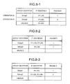
- Fig. 8-1 is one example of the grouping IF list according to the second embodiment.
- the group identifier, the IF identifier of the network IF constituting the group, and the priority of the group are associated with each other for each group in the group IF list.
- the operation and the group are in one-to-one correspondence.
- a group having a group identifier of "Group1" corresponds to the operation A and the priority of this group is "1”.
- a group having a group identifier of "Group2" corresponds to the operation B and the priority of the group is "2". Accordingly, in this case, the operation priority of the operation A is higher than that of the operation B.
- Fig. 7-1(a) when it is detected by the LAN-interface control program 100 that the traffic in the network IF 10 corresponding to the operation A has increased, as shown in Fig. 7-1(b) , the inactive network IF 20 is activated and two network IFs 10 and 20 are grouped. At this time, the grouped two network IFs 10 and 20 are associated with the operation A. Accordingly, the band used by the operation A can be expanded.
- Fig. 8-2 depicts the grouping IF list at the time of finishing the process in Fig. 7-1(b) .
- the network IFs 10 and 20 are allocated to the group "Group1" corresponding to the operation A and the network IF 30 is allocated to the group "Group2" corresponding to the operation B.
- the band control according to the operation priority can be also performed.
- the band control according to the operation priority in the server 1 according to the second embodiment is explained next with reference to Fig. 7-2 . After transition to a state shown in Fig. 7-1(b) , as shown in Fig. 7-2(c) , it is assumed that the traffic in the network IF 30 allocated to the operation B has increased.
- the band control of the network IF according to the operation priority is enabled. That is, the network IF already used by the operation A having low operation priority can be made the grouping target in the automatic band-expansion-control process, with respect to the operation B having high operation priority.
- the grouping of the network IF 20 already used by the operation A is released to deactivate the network IF 20 once, and then, the network IF 20 is activated again to perform grouping of the network IF 20 with the network IF 30.
- Fig. 8-3 depicts the grouping IF list at the time of finishing the process in Fig. 7-2(d) .
- the group to which the network IF 20 belongs is changed from "Group1" to "Group2”, and the network IF 20 is grouped with the network IF 30.
- the band can be preferentially expanded with respect to the operation with a high operation priority, regardless of the usage of the network IF.
- the network IF 20 is allocated to the operation B, any method can be used as the determination method of the network IF.
- the network IF 10 can be allocated to the operation B instead of the network IF 20.
- the network IF 20 is deactivated once and then activated again at the time of changing the operation using the network IF 2; however, grouping release and new grouping can be executed without performing the deactivation process. In this case, because setting before grouping release is left in the network IF 20, initialization is required before the new grouping.
- the operation using the network IF 20 is changed from the operation A to the operation B, and the traffic of data transmission can be preferentially reduced with respect to the operation B having the high operation priority.
- the band control according to the operation priority of respective operations is performed, thereby enabling to expand the band preferentially with respect to the operation with the high operation priority, regardless of the usage of the network IF.
- Fig. 9 depicts the hardware configuration of the server that executes the LAN-interface control program 100 according to the first and second embodiments.
- the server 1 according to the embodiments includes a plurality of network IFs 10 and 20, a CPU (Central Processing Unit) 40, a system memory 50, a UPA (Ultra Port Architecture) bus 60, and a PCI (Peripheral Component Interconnect) bus 70.
- a CPU Central Processing Unit
- UPA User Port Architecture
- PCI Peripheral Component Interconnect
- the network IFs 10 and 20 are connected to the LAN L3 switch (not shown), to transmit and receive data to and from external devices through the LAN L3 switch via the network.
- the CPU 40 executes the LAN-interface control program 100 and the like.
- the system memory 50 is a readable and writable memory for storing the OS, the LAN-interface control program 100, and the like.
- the UPA bus 60 functions as a system bus, and connects the CPU 40, the system memory 50, and a chip set (not shown).
- the PCI bus 70 is connected to the network IFs 10 and 20, for transmitting and receiving data to and from the CPU 40 and the system memory 50 via a bridge and the UPA bus 60.
- the network interface control program and the network interface controller according to the present invention are useful for a server including a plurality of network interfaces, and particularly, are suitable when it is required to provide an appropriate communication band by automatically executing activation or deactivation of the network interface according to the communication condition and expanding or reducing the band.
Landscapes
- Engineering & Computer Science (AREA)
- Computer Networks & Wireless Communication (AREA)
- Signal Processing (AREA)
- Data Exchanges In Wide-Area Networks (AREA)
- Small-Scale Networks (AREA)
Abstract
Description
- The present invention relates to a network interface control program and a network interface controller for controlling a plurality of network interfaces connected to a network repeater, and, more particularly to a network interface control program and a network interface controller for automatically executing band expansion/reduction according to communication situation to provide an appropriate communication band.
- Conventionally, band expansion/reduction processing in communication via the network interface (network IF) has been performed manually. For example, in a server, when a communication failure such as delay in a communication response time occurs due to an increase of communication traffic, as a method for handling the problem, a cause thereof is specified by human determination based on statistics of CPU load and data transmission amount, and an operation for adding the network IF is performed manually to expand the band in communications. With this method, however, manual traffic management and an expansion operation are required, thereby causing a large cost increase.
- For the expansion of the communication band, human labor can be reduced by securing beforehand a broadband transmission line capable of preventing a communication failure due to an increase of the traffic beforehand. Particularly, when a cost aspect is taken into consideration, a method of forming a plurality of transmission lines between the network IF and a LAN switch is effective as a method of band expansion. As one example thereof, there is link aggregation prescribed in IEEE 802.3ad (for example, see Nonpatent Literature 1). In the link aggregation, a plurality of transmission lines is virtually regarded as one transmission line, so that the communication band can be expanded and redundancy can be provided to the transmission line.
- Nonpatent Literature 1: IEEE P802.3ad Link Aggregation Task Force [Searched on August 23rd, 2005], Internet <URL:http://grouper.ieee.org/groups/802/3/ad/index.html>
- In the link aggregation prescribed in IEEE 802.3ad, there is provided a function for recovering a communication state, when a communication failure occurs in a part of a plurality of grouped communication lines, and the LAN switch detects the failure, by excluding the transmission line having the detected failure from a grouping target. However, this function only corresponds to a communication failure detectable by the LAN switch, such as physical disconnection, and flexible band change cannot be executed corresponding to a temporary communication failure such as a traffic increase.
- In view of the above problems, it is an object of the present invention to provide a network interface program and a network interface controller for automatically executing band expansion/reduction according to band usage, to provide an appropriate communication band.
- To solve the problems and achieve the object, a network interface control program according to the present invention as recited in
claim 1 is for causing a computer comprising a plurality of network interfaces connected to a network repeater to execute a traffic-increase detection step of detecting a traffic increase in each network interface; and a band expansion step of expanding a communication band by grouping a network interface in which the traffic increase is detected in the traffic-increase detection step and another unused network interface. - According to the invention of
claim 1, a traffic increase in a network interface is detected, thereby grouping the network interface having the detected traffic increase and another unused network interface. Accordingly, when the traffic increases, the communication band can be automatically expanded. - The network interface control program as recited in
claim 2 according to the invention ofclaim 1 further causes the computer to execute an inactive-interface detection step of detecting an inactive network interface; and a hardware activation step of activating the network interface detected in the inactive-interface detection step, wherein in the band expansion step, the network interface activated in the hardware activation step is grouped. - According to the invention of
claim 2, an inactive network interface is detected, the detected network interface is activated, and the activated network interface is grouped. Accordingly, the inactive network interface can be made a grouping target. - In the network interface control program as recited in
claim 3 according to the invention ofclaim 1, in the traffic-increase detection step, when at least one of a transmission waiting frequency for a given length of time and a reception depletion frequency for a given length of time is a predetermined threshold or higher in the network interface, it is determined that the traffic is increased. - According to the invention of
claim 3, when at least one of a transmit-waiting frequency for a given length of time and a reception suspension frequency for a given length of time in the network interface becomes a predetermined threshold or higher, it is determined that the traffic has increased. Accordingly, the traffic increase can be automatically detected. - The network interface control program as recited in
claim 4 according to the invention ofclaim 1 further causes the computer to execute a traffic-decrease detection step of detecting a traffic decrease in the network interface; and a band reduction step of reducing the communication band by excluding the network interface in which the traffic decrease is detected in the traffic-decrease detection step, from a group including the network interface. - According to the invention of
claim 4, a traffic decrease in the network interface is detected, and the network interface is excluded from the group including the network interface having the detected traffic decrease. Accordingly, when the traffic has decreased, the communication band can be automatically reduced. - The network interface control program as recited in
claim 5 according to the invention ofclaim 4 further causes the computer to execute a hardware deactivation step of deactivating the network interface excluded from the group in the band reduction step. - According to the invention of
claim 5, the network interface excluded from the group is deactivated. Accordingly, an unused network interface can be suspended. - In the network interface control program as recited in
claim 6 according to the invention ofclaim 4, in the traffic-decrease detection step, when the number of transmission packets for a given length of time in the network interface is a predetermined threshold or less, it is determined that the traffic is decreased. - According to the invention of
claim 6, when the number of transmission packets for a given length of time in the network interface becomes a predetermined threshold or less, it is determined that the traffic has decreased. Accordingly, the traffic decrease can be automatically detected. - In the network interface control program as recited in claim 7 according to the invention of
claim 1, the computer simultaneously performs a plurality of operations each having an operation priority, wherein the program causes the computer a grouping release step when there is no unused network interface and a traffic increase is detected in a first network interface in the traffic-increase detection step, the grouping release step being of excluding a second network interface used for an operation with a lower operation priority than an operation using the first network interface from a group including the second network interface, wherein in the band expanding step, the fist network interface in which the traffic increase is detected in the traffic-increase detection step and the second network interface excluded from the group in the grouping release step are grouped. - According to the invention of claim 7, with respect to a network interface used by an operation with the lower operation priority than an operation using a network interface having increased traffic, the network interface with the lower operation priority is excluded from the group including this network interface, and the network interface having the increased traffic and the network interface excluded from the group are grouped. Accordingly, the communication band can be preferentially expanded for the operation having the high operation priority.
- In the network interface control program as recited in claim 8 according to the invention of any one of
claims 1 to 7, the grouping is a process by link aggregation prescribed in IEEE 802.3ad. - According to the invention of claim 8, because grouping is performed according to the link aggregation prescribed in IEEE 802.3ad, grouping can be performed by using a known technique.
- A network interface controller as recited in claim 9 includes a plurality of network interfaces connected to a network repeater, the network interface controller and includes a traffic-increase detection means for detecting a traffic increase in each network interface; and a band expansion means for expanding a communication band by grouping a network interface in which the traffic increase is detected in the traffic-increase detection means and another unused network interface.
- According to the invention of claim 9, a traffic increase in a network interface is detected, thereby grouping the network interface having the detected traffic increase and another unused network interface. Accordingly, when the traffic increases, the communication band can be automatically expanded.
- The network interface controller as recited in
claim 10 according to the invention of claim 9 further includes a traffic-decrease detection means for detecting a traffic decrease in the network interface; and a band reduction means for reducing the communication band by excluding the network interface in which the traffic decrease is detected in the traffic-decrease detection means, from a group including the network interface. - According to the invention of
claim 10, a traffic decrease in the network interface is detected, and the network interface is excluded from the group including the network interface having the detected traffic decrease. Accordingly, when the traffic has decreased, the communication band can be automatically reduced. - According to the inventions of
claims 1 and 9, the communication band can be automatically expanded when the traffic increases. Accordingly, there is an effect that an appropriate communication band can be provided. - According to the invention of
claim 2, because an inactive network interface can be made as a grouping target, there is an effect that the network interface can be effectively used. - According to the invention of
claim 3, because a traffic increase can be automatically detected, there is an effect that the communication band can be automatically controlled. - According to the inventions of
claims - According to the invention of
claim 5, because an unused network interface can be suspended, there is an effect that power saving can be enabled. - According to the invention of
claim 6, because a traffic decrease can be automatically detected, there is an effect that the communication band can be automatically controlled. - According to the invention of claim 7, because the communication band can be preferentially expanded for the operation having high operation priority, there is an effect that the band can be controlled according to the operation priority.
- According to the invention of claim 8, because grouping can be performed by using a known technique, there is an effect that grouping can be easily performed.
- [
Fig. 1] Fig. 1 is an explanatory diagram for explaining a network configuration to which a LAN-interface control program according to a first embodiment is applied. - [
Fig. 2] Fig. 2 is a functional block diagram of a configuration of the LAN-interface control program according to the first embodiment. - [
Fig. 3] Fig. 3 is one example of a grouping IF list. - [
Fig. 4] Fig. 4 is one example of the grouping IF list. - [
Fig. 5] Fig. 5 is a flowchart of a process procedure of an automatic band-expansion-control process according to the first embodiment. - [
Fig. 6] Fig. 6 is a flowchart of a process procedure of an automatic band-reduction-control process according to the first embodiment. - [
Fig. 7-1] Fig. 7-1 is an explanatory diagram (1) of an operation of a LAN-interface control program according to a second embodiment. - [
Fig. 7-2] Fig. 7-2 is an explanatory diagram (2) of an operation of the LAN-interface control program according to the second embodiment. - [
Fig. 8-1] Fig. 8-1 is one example of a grouping IF list according to the second embodiment. - [
Fig. 8-2] Fig. 8-2 depicts the grouping IF list at the time of finishing a process inFig. 7-1(b) . - [
Fig. 8-3] Fig. 8-3 depicts the grouping IF list at the time of finishing a process inFig. 7-2(d) . - [
Fig. 9] Fig. 9 depicts a hardware configuration of a server that executes the LAN-interface control program according to the first and second embodiments. -
- 1
- Server
- 2
-
LAN layer 3 switch - 3
- Network
- 10, 20, 30
- Network interface (Network IF)
- 100
- LAN-interface control program
- 110
- Transmission data controller
- 120
- Host interface controller
- 130
- Grouping-IF-list storage unit
- 140
- Network-IF-list storage unit
- 150
- Grouping managing unit
- 160
- Grouping controller
- 170
- Hardware controller
- Exemplary embodiments of a network interface control program and a network interface controller according to the present invention will be explained below in detail with reference to the accompanying drawings. Note that the present invention is not limited to the embodiments.
- A network configuration to which an LAN-interface control program according to the first embodiment is applied is explained.
Fig. 1 is an explanatory diagram for explaining the network configuration, to which the LAN-interface control program according to the first embodiment is applied. Aserver 1 shown inFig. 1 is a computer used as a Web server, a mail server, a database server, or the like. Theserver 1 is connected to anetwork 3 via aLAN layer 3 switch (L3 switch) 2, for transmitting and receiving data to/from anotherserver 4, andterminals network 3. - The
server 1 includes twonetwork IFs network IFs LAN L3 switch 2 by a separate transmission line, and also connected to thenetwork 3 via theLAN L3 switch 2. - A LAN-
interface control program 100 according to the first embodiment is executed on theserver 1, and functions as a device driver that controls thenetwork IFs interface control program 100 detects transmission line traffic in the twonetwork IFs network IFs - The grouping here represents a process by the link aggregation, and the two transmission lines separately formed for the two
network IFs network IFs - The
LAN L3 switch 2 functions as a router and connects theserver 1 and thenetwork 3 with each other. TheLAN L3 switch 2 allows link aggregation, and when thenetwork IFs interface control program 100, theLAN L3 switch 2 can virtually regard the twonetwork IFs - The configuration of the LAN-
interface control program 100 according to the first embodiment is explained next.Fig. 2 is a functional block diagram of the configuration of the LAN-interface control program 100 according to the first embodiment. As shown inFig. 2 , the LAN-interface control program 100 includes atransmission data controller 110, ahost interface controller 120, a grouping-IF-list storage unit 130, a network-IF-list storage unit 140, agrouping managing unit 150, agrouping controller 160, and ahardware controller 170. - The
transmission data controller 110 is a processing unit that controls transmission of data between thenetwork IFs host interface controller 120. That is, thetransmission data controller 110 processes the data received from thenetwork IFs host interface controller 120. Further, thetransmission data controller 110 processes the data received from thehost interface controller 120, and transmits the data to thenetwork IFs - The
transmission data controller 110 detects a traffic decrease in the network IF to notify thegrouping managing unit 150 of the decrease. Specifically, when the number of transmission packets to and from the network IF is 0 for a predetermined period of time, thetransmission data controller 110 determines that the traffic in the network IF has decreased. A determination method of the traffic decrease is not limited to the method, and for example, when the number of transmission packets is less than a predetermined threshold, it can be determined that the traffic has decreased. - The
host interface controller 120 is a processing unit that operates as an interface of a host protocol such as IP (Internet Protocol) and ICMP (Internet Control Message Protocol), and an OS (Operating System). - The grouping-IF-
list storage unit 130 stores a grouping IF list, which is used at the time of grouping therespective network IFs Fig. 3 is one example of the grouping IF list. In the grouping IF list, as shown inFig. 3 , a group identifier and an IF identifier of the network IF constituting the group are associated with each other. - The group identifier indicates a group to which the network IF belongs. However, a group having "unused" as the group identifier is allocated to a deactivated network IF. In
Fig. 3 , the network IF having "IF1" as the IF identifier belongs to a group "Group1", and the network IF having "IF2" as the IF identifier is an "unused" group, that is, inactive. - The network-IF-
list storage unit 140 stores a network IF list indicating conditions of therespective network IFs Fig. 4 is one example of the network IF list. As shown inFig. 4 , in the network IF list, the IF identifier, the group identifier, a transmission-buffer waiting frequency, and a reception-buffer depletion frequency are associated with each other for each network IF. - The transmission-buffer waiting frequency indicates a frequency of transmit-wait occurred in a given length of time in the
transmission data controller 110. The transmit-wait occurs when there is no space in a transmission buffer of thenetwork IFs transmission data controller 110 to thenetwork IFs transmission data controller 110 counts the frequency of transmit-wait, and stores the frequency of transmit-wait in the network-IF-list storage unit 140 with a lapse of a certain time. - The reception-buffer depletion frequency indicates a frequency of pause frames transmitted in a given length of time in the
network IFs network IFs LAN L3 switch 2 by thenetwork IFs network IFs list storage unit 140 with a lapse of a certain time. The transmission-buffer waiting frequency and the reception-buffer depletion frequency are used as traffic statistical information at the time of detecting the traffic increase. - The
grouping managing unit 150 is a processing unit that manages information relating to the grouping of the network IF. Thegrouping managing unit 150 monitors values of the transmission-buffer waiting frequency and the reception-buffer depletion frequency stored in the network-IF-list storage unit 140, and determines that the traffic has increased when at least one of these values becomes equal to or larger than a predetermined threshold. - When having determined that the traffic has increased, the
grouping managing unit 150 instructs thehardware controller 170 to activate an inactive network IF, and instructs thegrouping controller 160 to group the network IFs, thereby expanding the band. Thegrouping managing unit 150 updates the grouping IF list stored in the grouping-IF-list storage unit 130 and the network IF list stored in the network-IF-list storage unit 140 based on the instruction. - When detection of the traffic decrease in the network IF is notified by the
transmission data controller 110, thegrouping managing unit 150 instructs thegrouping controller 160 to release the grouping of the network IF, and instructs thehardware controller 170 to deactivate the network IF. Thegrouping managing unit 150 updates the grouping IF list stored in the grouping-IF-list storage unit 130 and the network IF list stored in the network-IF-list storage unit 140. - The
grouping controller 160 is a processing unit that sets the link aggregation. Upon reception of a grouping instruction from thegrouping managing unit 150, thegrouping controller 160 groups the relevant network IF. Upon reception of a grouping release instruction from thegrouping managing unit 150, thegrouping controller 160 releases the grouping of the relevant network IF. After executing grouping or release of the grouping, thegrouping controller 160 outputs a change result of a data transmission route to thetransmission data controller 110. - The
hardware controller 170 is a processing unit that performs various settings relating to the operation of thenetwork IFs network IFs grouping managing unit 150, thehardware controller 170 activates the relevant network IF. Upon reception of a deactivation instruction from thegrouping managing unit 150, thehardware controller 160 deactivates the relevant network IF. - Thus, the
transmission data controller 110 or thegrouping managing unit 150 in the LAN-interface control program 100 detects an increase or decrease of the traffic in therespective network IFs grouping managing unit 150 executes grouping control with respect to thenetwork IFs network IFs - A process procedure of automatic band-expansion-control process according to the first embodiment is explained next.
Fig. 5 is a flowchart of the process procedure of the automatic band-expansion-control process according to the first embodiment. The automatic band-expansion-control process is performed regularly with a lapse of a certain time. Before the automatic band-expansion-control process is performed, a group having "unused" group identifier is allocated to an inactive network IF to set so that the inactive network IF becomes a grouping target. Grouping setting is also performed with respect to theLAN L3 switch 2 in the same manner. - The
grouping managing unit 150 first determines whether there is a traffic increase (step S101). Specifically, thegrouping managing unit 150 refers to the network-IF-list storage unit 140 to determine whether at least one of the transmission-buffer waiting frequency and the reception-buffer depletion frequency is equal to or larger than the predetermined threshold. The determination is made before delay in a communication response time with theserver 1 is detected by anotherserver 4 or theterminals network 3. - When it is determined that there is a traffic increase (step S101, Yes), the
grouping managing unit 150 refers to the grouping-IF-list storage unit 130, to check if there is a network IF belonging to an "unused" group (step S102). For example, when the network IF 20 is inactive, the network IF 20 is detected as the network IF belonging to the "unused" group. - When there is the network IF belonging to the "unused" group (step S102, Yes), the
grouping managing unit 150 instructs thegrouping controller 160 and thehardware controller 170 to expand the band, and updates the grouping-IF-list storage unit 130 and the network-IF-list storage unit 140 (step S103). As the band expansion instruction, specifically, thegrouping managing unit 150 notifies thehardware controller 170 to activate the inactive network IF, and notifies thegrouping controller 160 to group the network IF, whose activation has been notified, and the other network IF having the traffic increase. - After performing step S103, the
hardware controller 170 activates the inactive network IF (step S104). Thegrouping controller 160 then groups the two network IFs (step S105). Accordingly, the two network IFs can be shared to expand the band. - On the other hand, when there is no network IF belonging to the "unused" group (step S102, No), because all the network IFs already belong to other groups, the band cannot be expanded any more. Therefore, the process finishes.
- Thus, when it is determined that there is a traffic increase in the network IF, the
hardware controller 170 activates a network IF, and thegrouping controller 160 groups the activated network IF and the network IF being used. Accordingly, a traffic detection process, an activation process of the network IF, and a grouping process of the network IF can be automatically performed collectively only by theserver 1, thereby enabling to automatically expand the band. - A process procedure of an automatic band-reduction-control process according to the first embodiment is explained next.
Fig. 6 is a flowchart of the process procedure of the automatic band-reduction-control process according to the first embodiment. The automatic band-reduction-control process is regularly performed with a lapse of a certain time when twonetwork IFs - The
transmission data controller 110 determines whether there is a traffic decrease (step S201). As the detection process, when the number of transmission packets in a certain network IF (for example, network IF 20) is 0 for a predetermined period of time, thetransmission data controller 110 determines that the traffic in the network IF has decreased. - When the traffic decrease is determined (step S201, Yes), the
grouping managing unit 150 instructs thegrouping controller 160 and thehardware controller 170 to reduce the band, and updates the grouping-IF-list storage unit 130 and the network-IF-list storage unit 140 (step S202). As the band reduction instruction, specifically, thegrouping managing unit 150 notifies thegrouping controller 160 to release the grouping of the network IF having the detected traffic decrease, and notifies thehardware controller 170 to deactivate the network IF. - After performing step S202, the
grouping controller 160 releases the grouping of the network IF 20 (step S203). As a process for releasing the grouping, thegrouping controller 160 changes the grouping identifier in the grouping-IF-list storage unit 130 and the network-IF-list storage unit 140 to "unused". Thehardware controller 170 deactivates the network IF 20 (step S204). Accordingly, while sustaining communication by the network IF 10 on one side, the network IF 20 on the other side is deactivated, thereby enabling to reduce the band. - Thus, when the traffic decrease in the network IF is determined, the
grouping controller 160 releases the grouping of the network IF, and thehardware controller 170 deactivates the network IF, thereby enabling to reduce a memory resource and an operating power relating to the unused network IF. This process can be also automatically performed collectively, without requiring any manual operation, as in the automatic band-expansion-control process inFig. 5 . - In the LAN-
interface control program 100 according to the first embodiment, when a traffic increase in the network IF is detected by thegrouping managing unit 150, thegrouping managing unit 150 instructs thegrouping controller 160 and thehardware controller 170 to expand the band. Thehardware controller 170 activates an inactive network IF and thegrouping controller 160 groups the network IF, thereby enabling to automatically expand the band. - In the LAN-
interface control program 100 according to the first embodiment, when a traffic decrease in the network IF is detected by thetransmission data controller 110, thegrouping managing unit 150 instructs thegrouping controller 160 and thehardware controller 170 to reduce the band. Thegrouping controller 160 releases the grouping and thehardware controller 170 deactivates the network IF, thereby enabling to automatically reduce an unnecessary band and to reduce the memory resource and the operating power. Accordingly, an appropriate communication band can be provided by automatically executing the band expansion/reduction according to the communication situation. - In the second embodiment, band control according to the operation priority in the case of simultaneously performing a plurality of operations on the server is explained.
Figs. 7-1 and7-2 are explanatory diagrams of an operation of the LAN-interface control program 100 according to the second embodiment. The LAN-interface control program 100 according to the second embodiment is different from that of the first embodiment in that setting relating to the operation priority is included in the grouping IF list. In the second embodiment, a case that theserver 1 includes three network IFs is explained, however, the number of the network IF is not limited to three, and only required to be equal to or more than three. - As shown in
Fig. 7-1(a) , transmission of data relating to two operations A and B performed by theserver 1 is allocated torespective network IFs 10 to 30 by the LAN-interface control program 100 and executed. Therespective network IFs 10 to 30 are connected to the network via theLAN L3 switch 2, and the transmission of data relating to the operations A and B is performed via these network IFs. InFig. 7-1(a) , the network IF 10 is allocated to the operation A and the network IF 30 is allocated to the operation B, and the network IF 20 is in an inactive state. - The operation here represents an operation between server networks, and for example, when the
server 1 is a Web server, the operation represents user access, when theserver 1 is a mail server, the operation represents email distribution, and when theserver 1 is a database server, the operation represents data request traffic. - The operation priority is preset for the respective operations A and B, and the setting of the operation priority is stored in the grouping-IF-
list storage unit 130. The LAN-interface control program 100 performs grouping control of thenetwork IFs 10 to 30 according to the operation priority. -
Fig. 8-1 is one example of the grouping IF list according to the second embodiment. As shown inFig. 8-1 , the group identifier, the IF identifier of the network IF constituting the group, and the priority of the group are associated with each other for each group in the group IF list. The operation and the group are in one-to-one correspondence. InFig. 8-1 , a group having a group identifier of "Group1" corresponds to the operation A and the priority of this group is "1". A group having a group identifier of "Group2" corresponds to the operation B and the priority of the group is "2". Accordingly, in this case, the operation priority of the operation A is higher than that of the operation B. - An automatic band-expansion-control process in the
server 1 according to the second embodiment is explained next with reference toFig. 7-1 . Because the process at this time is the same as the automatic band-expansion-control process in the first embodiment shown inFig. 5 , it is explained briefly. - As shown in
Fig. 7-1(a) , when it is detected by the LAN-interface control program 100 that the traffic in the network IF 10 corresponding to the operation A has increased, as shown inFig. 7-1(b) , the inactive network IF 20 is activated and twonetwork IFs network IFs -
Fig. 8-2 depicts the grouping IF list at the time of finishing the process inFig. 7-1(b) . As shown inFig. 8-2 , thenetwork IFs - The band control according to the operation priority can be also performed. The band control according to the operation priority in the
server 1 according to the second embodiment is explained next with reference toFig. 7-2 . After transition to a state shown inFig. 7-1(b) , as shown inFig. 7-2(c) , it is assumed that the traffic in the network IF 30 allocated to the operation B has increased. - When the operation priority of the operation B is higher than that of the operation A, even if band expansion with respect to the operation B is attempted, the remaining two
network IFs - In the second embodiment, therefore, the band control of the network IF according to the operation priority is enabled. That is, the network IF already used by the operation A having low operation priority can be made the grouping target in the automatic band-expansion-control process, with respect to the operation B having high operation priority.
- That is, as shown in
Fig. 7-2(d) , the grouping of the network IF 20 already used by the operation A is released to deactivate the network IF 20 once, and then, the network IF 20 is activated again to perform grouping of the network IF 20 with the network IF 30. -
Fig. 8-3 depicts the grouping IF list at the time of finishing the process inFig. 7-2(d) . As shown inFig. 8-3 , the group to which the network IF 20 belongs is changed from "Group1" to "Group2", and the network IF 20 is grouped with the network IF 30. - Thus, by performing the band control according to the operation priority, the band can be preferentially expanded with respect to the operation with a high operation priority, regardless of the usage of the network IF.
- While the network IF 20 is allocated to the operation B, any method can be used as the determination method of the network IF. The network IF 10 can be allocated to the operation B instead of the network IF 20.
- The network IF 20 is deactivated once and then activated again at the time of changing the operation using the network IF 2; however, grouping release and new grouping can be executed without performing the deactivation process. In this case, because setting before grouping release is left in the network IF 20, initialization is required before the new grouping.
- Accordingly, the operation using the network IF 20 is changed from the operation A to the operation B, and the traffic of data transmission can be preferentially reduced with respect to the operation B having the high operation priority.
- As described above, in the second embodiment, when a plurality of operations is executed simultaneously, the band control according to the operation priority of respective operations is performed, thereby enabling to expand the band preferentially with respect to the operation with the high operation priority, regardless of the usage of the network IF.
- The hardware configuration of the
server 1 that executes the LAN-interface control program 100 according to the first and second embodiments is explained next.Fig. 9 depicts the hardware configuration of the server that executes the LAN-interface control program 100 according to the first and second embodiments. Theserver 1 according to the embodiments includes a plurality ofnetwork IFs system memory 50, a UPA (Ultra Port Architecture)bus 60, and a PCI (Peripheral Component Interconnect)bus 70. - The
network IFs CPU 40 executes the LAN-interface control program 100 and the like. Thesystem memory 50 is a readable and writable memory for storing the OS, the LAN-interface control program 100, and the like. - The
UPA bus 60 functions as a system bus, and connects theCPU 40, thesystem memory 50, and a chip set (not shown). ThePCI bus 70 is connected to thenetwork IFs CPU 40 and thesystem memory 50 via a bridge and theUPA bus 60. - The network interface control program and the network interface controller according to the present invention are useful for a server including a plurality of network interfaces, and particularly, are suitable when it is required to provide an appropriate communication band by automatically executing activation or deactivation of the network interface according to the communication condition and expanding or reducing the band.
Claims (10)
- A network interface control program for causing a computer comprising a plurality of network interfaces connected to a network repeater to execute:a traffic-increase detection step of detecting a traffic increase in each network interface; anda band expansion step of expanding a communication band by grouping a network interface in which the traffic increase is detected in the traffic-increase detection step and another unused network interface.
- The network interface control program according to claim 1, further causing the computer to execute:an inactive-interface detection step of detecting an inactive network interface; anda hardware activation step of activating the network interface detected in the inactive-interface detection step, whereinin the band expansion step, the network interface activated in the hardware activation step is grouped.
- The network interface control program according to claim 1, wherein in the traffic-increase detection step, when at least one of a transmission waiting frequency for a given length of time and a reception depletion frequency for a given length of time is a predetermined threshold or higher in the network interface, it is determined that the traffic is increased.
- The network interface control program according to claim 1, further causing the computer to execute:a traffic-decrease detection step of detecting a traffic decrease in the network interface; anda band reduction step of reducing the communication band by excluding the network interface in which the traffic decrease is detected in the traffic-decrease detection step, from a group including the network interface.
- The network interface control program according to claim 4, further causing the computer to execute a hardware deactivation step of deactivating the network interface excluded from the group in the band reduction step.
- The network interface control program according to claim 4, wherein in the traffic-decrease detection step, when the number of transmission packets for a given length of time in the network interface is a predetermined threshold or less, it is determined that the traffic is decreased.
- The network interface control program according to claim 1, wherein
the computer simultaneously performs a plurality of operations each having an operation priority,
wherein the program causes the computer a grouping release step when there is no unused network interface and a traffic increase is detected in a first network interface in the traffic-increase detection step, the grouping release step being of excluding a second network interface used for an operation with a lower operation priority than an operation using the first network interface from a group including the second network interface, wherein
in the band expanding step, the fist network interface in which the traffic increase is detected in the traffic-increase detection step and the second network interface excluded from the group in the grouping release step are grouped. - The network interface control program according to any one of claims 1 to 7, wherein the grouping is a process by link aggregation prescribed in IEEE 802.3ad.
- A network interface controller which includes a plurality of network interfaces connected to a network repeater, the network interface controller comprising:a traffic-increase detection means for detecting a traffic increase in each network interface; anda band expansion means for expanding a communication band by grouping a network interface in which the traffic increase is detected in the traffic-increase detection means and another unused network interface.
- The network interface controller according to claim 9, further comprising:a traffic-decrease detection means for detecting a traffic decrease in the network interface; anda band reduction means for reducing the communication band by excluding the network interface in which the traffic decrease is detected in the traffic-decrease detection means, from a group including the network interface.
Applications Claiming Priority (1)
| Application Number | Priority Date | Filing Date | Title |
|---|---|---|---|
| PCT/JP2005/016147 WO2007029297A1 (en) | 2005-09-02 | 2005-09-02 | Network interface control program and network interface controller |
Publications (2)
| Publication Number | Publication Date |
|---|---|
| EP1942608A1 true EP1942608A1 (en) | 2008-07-09 |
| EP1942608A4 EP1942608A4 (en) | 2011-01-12 |
Family
ID=37835434
Family Applications (1)
| Application Number | Title | Priority Date | Filing Date |
|---|---|---|---|
| EP05781412A Withdrawn EP1942608A4 (en) | 2005-09-02 | 2005-09-02 | NETWORK INTERFACE CONTROL PROGRAM AND NETWORK INTERFACE CONTROLLER |
Country Status (5)
| Country | Link |
|---|---|
| US (1) | US7773526B2 (en) |
| EP (1) | EP1942608A4 (en) |
| JP (1) | JPWO2007029297A1 (en) |
| CN (1) | CN101248628A (en) |
| WO (1) | WO2007029297A1 (en) |
Families Citing this family (16)
| Publication number | Priority date | Publication date | Assignee | Title |
|---|---|---|---|---|
| JP4920391B2 (en) * | 2006-01-06 | 2012-04-18 | 株式会社日立製作所 | Computer system management method, management server, computer system and program |
| ES2582884T3 (en) * | 2007-10-31 | 2016-09-15 | Telefonaktiebolaget Lm Ericsson (Publ) | Networks that have multiple paths between nodes and nodes for such a network |
| JP5113093B2 (en) * | 2009-01-06 | 2013-01-09 | Kddi株式会社 | Network management system and management method |
| JP5293958B2 (en) * | 2009-04-01 | 2013-09-18 | 日本電気株式会社 | Data processing apparatus, data processing method, and program |
| JP2010283747A (en) * | 2009-06-08 | 2010-12-16 | Nec Corp | Communication device |
| WO2012053061A1 (en) | 2010-10-19 | 2012-04-26 | 富士通株式会社 | Switch device, information processing device, switch device control method and program |
| JP5534026B2 (en) * | 2010-11-16 | 2014-06-25 | 富士通株式会社 | Communication system control method, communication system, and communication apparatus |
| JP5779982B2 (en) * | 2011-05-24 | 2015-09-16 | 東芝三菱電機産業システム株式会社 | Duplex control system |
| US20130003559A1 (en) * | 2011-06-30 | 2013-01-03 | Broadcom Corporation | Adaptive Power Savings for Aggregated Resources |
| US9042383B2 (en) * | 2011-06-30 | 2015-05-26 | Broadcom Corporation | Universal network interface controller |
| JP2013048427A (en) * | 2012-09-13 | 2013-03-07 | Telefon Ab L M Ericsson | Networks having multiple paths between nodes and nodes for such network |
| US9253121B2 (en) | 2012-12-31 | 2016-02-02 | Broadcom Corporation | Universal network interface controller |
| JP6117585B2 (en) * | 2013-03-27 | 2017-04-19 | Necエンジニアリング株式会社 | Link aggregation control device, link aggregation control method, and link aggregation control program |
| CN103595810A (en) * | 2013-11-22 | 2014-02-19 | 浪潮电子信息产业股份有限公司 | Network self-adaptive method in distributed file system |
| CN110535777B (en) * | 2019-08-12 | 2022-07-12 | 新华三大数据技术有限公司 | Access request control method and device, electronic equipment and readable storage medium |
| CN111949464B (en) * | 2020-08-28 | 2025-01-28 | 海光信息技术股份有限公司 | A CPU network interface adaptability test board, test system and test method |
Family Cites Families (10)
| Publication number | Priority date | Publication date | Assignee | Title |
|---|---|---|---|---|
| US6151297A (en) * | 1997-07-08 | 2000-11-21 | Hewlett-Packard Company | Method and system for link level server/switch trunking |
| JP3223352B2 (en) | 1997-11-25 | 2001-10-29 | 株式会社超高速ネットワーク・コンピュータ技術研究所 | Local area network bandwidth control method |
| JP3322212B2 (en) * | 1998-05-15 | 2002-09-09 | 日本電気株式会社 | Method and apparatus for controlling load balance of communication board and machine-readable recording medium recording program |
| JP4141106B2 (en) * | 2001-02-06 | 2008-08-27 | 富士通株式会社 | Bandwidth control device |
| JP4014996B2 (en) * | 2002-10-15 | 2007-11-28 | 三菱電機株式会社 | Optical switch application node and optical network system |
| WO2004051955A1 (en) * | 2002-11-29 | 2004-06-17 | Fujitsu Limited | Communication unit, control method and program |
| AU2003221109A1 (en) * | 2003-03-31 | 2004-10-25 | Fujitsu Limited | Data communication load distribution control program and data load distribution control method |
| US8285881B2 (en) * | 2003-09-10 | 2012-10-09 | Broadcom Corporation | System and method for load balancing and fail over |
| US7729361B2 (en) * | 2006-02-24 | 2010-06-01 | Cisco Technology, Inc. | Method and system for power-efficient adaptive link aggregation |
| US8817817B2 (en) * | 2007-06-06 | 2014-08-26 | Hewlett-Packard Development Company, L.P. | Method for ethernet power savings on link aggregated groups |
-
2005
- 2005-09-02 JP JP2007534200A patent/JPWO2007029297A1/en active Pending
- 2005-09-02 WO PCT/JP2005/016147 patent/WO2007029297A1/en not_active Ceased
- 2005-09-02 EP EP05781412A patent/EP1942608A4/en not_active Withdrawn
- 2005-09-02 CN CNA2005800513800A patent/CN101248628A/en active Pending
-
2008
- 2008-02-28 US US12/039,492 patent/US7773526B2/en not_active Expired - Fee Related
Also Published As
| Publication number | Publication date |
|---|---|
| US7773526B2 (en) | 2010-08-10 |
| CN101248628A (en) | 2008-08-20 |
| WO2007029297A1 (en) | 2007-03-15 |
| EP1942608A4 (en) | 2011-01-12 |
| JPWO2007029297A1 (en) | 2009-03-26 |
| US20080159130A1 (en) | 2008-07-03 |
Similar Documents
| Publication | Publication Date | Title |
|---|---|---|
| US7773526B2 (en) | Network interface control program and network interface controller | |
| US20170048123A1 (en) | System for controlling switch devices, and device and method for controlling system configuration | |
| US9532359B2 (en) | Resource allocation method and device | |
| EP2352253A1 (en) | Method and apparatus for protecting link aggregation group of ethernet ring | |
| JP2010050857A (en) | Route control apparatus and packet discarding method | |
| JP2013246642A (en) | Multiprocessor system, and interprocessor communication method | |
| CN104104570A (en) | Aggregation processing method in IRF (Intelligent Resilient Framework) system and device | |
| CN106533736B (en) | Network equipment restarting method and device | |
| CN103973560A (en) | Device and method for fault treatment of stack links in IRF (intelligent resilient framework) system | |
| US10750499B2 (en) | Method, device and system for controlling air interface resource | |
| CN106453124A (en) | Traffic scheduling method and device | |
| CN111130943B (en) | Method for realizing fast ring network switching, switch and computer readable storage medium | |
| CN103200093A (en) | Method and device for improving processing performance of multiple virtual router redundancy protocol (VRRP) back-up sets | |
| WO2021073367A1 (en) | Data processing method, device, and system | |
| CN103338524A (en) | Wireless access method, wireless access device, wireless access system, access controller and access point equipment | |
| EP3024160B1 (en) | Control method, device and optical transceiver | |
| US9065862B2 (en) | Communication device, method for controlling the communication device, and communication system | |
| CN110677358A (en) | Message processing method and network equipment | |
| US11522762B2 (en) | Coordination device and method for providing control applications via a communication network for transmitting time-critical data | |
| EP2953299B1 (en) | Protection switching method, system and node | |
| CN108667640A (en) | Communication method and equipment, network access system | |
| WO2016061992A1 (en) | Service transmission method and device | |
| JP6979913B2 (en) | Information processing equipment, information processing methods, and programs | |
| JP5476841B2 (en) | Relay device and relay method | |
| JP5169848B2 (en) | Power saving method in server apparatus, power saving control program, and server apparatus |
Legal Events
| Date | Code | Title | Description |
|---|---|---|---|
| PUAI | Public reference made under article 153(3) epc to a published international application that has entered the european phase |
Free format text: ORIGINAL CODE: 0009012 |
|
| 17P | Request for examination filed |
Effective date: 20080328 |
|
| AK | Designated contracting states |
Kind code of ref document: A1 Designated state(s): DE FR GB |
|
| DAX | Request for extension of the european patent (deleted) | ||
| RBV | Designated contracting states (corrected) |
Designated state(s): DE FR GB |
|
| A4 | Supplementary search report drawn up and despatched |
Effective date: 20101215 |
|
| RIC1 | Information provided on ipc code assigned before grant |
Ipc: H04L 12/56 20060101AFI20101209BHEP |
|
| 17Q | First examination report despatched |
Effective date: 20120731 |
|
| STAA | Information on the status of an ep patent application or granted ep patent |
Free format text: STATUS: THE APPLICATION IS DEEMED TO BE WITHDRAWN |
|
| 18D | Application deemed to be withdrawn |
Effective date: 20121211 |