EP1942275A1 - Variable displacement compressor - Google Patents
Variable displacement compressor Download PDFInfo
- Publication number
- EP1942275A1 EP1942275A1 EP06812092A EP06812092A EP1942275A1 EP 1942275 A1 EP1942275 A1 EP 1942275A1 EP 06812092 A EP06812092 A EP 06812092A EP 06812092 A EP06812092 A EP 06812092A EP 1942275 A1 EP1942275 A1 EP 1942275A1
- Authority
- EP
- European Patent Office
- Prior art keywords
- tilting
- sleeve
- drive shaft
- rotating member
- linkage
- Prior art date
- Legal status (The legal status is an assumption and is not a legal conclusion. Google has not performed a legal analysis and makes no representation as to the accuracy of the status listed.)
- Withdrawn
Links
Images





Classifications
-
- F—MECHANICAL ENGINEERING; LIGHTING; HEATING; WEAPONS; BLASTING
- F04—POSITIVE - DISPLACEMENT MACHINES FOR LIQUIDS; PUMPS FOR LIQUIDS OR ELASTIC FLUIDS
- F04B—POSITIVE-DISPLACEMENT MACHINES FOR LIQUIDS; PUMPS
- F04B27/00—Multi-cylinder pumps specially adapted for elastic fluids and characterised by number or arrangement of cylinders
- F04B27/08—Multi-cylinder pumps specially adapted for elastic fluids and characterised by number or arrangement of cylinders having cylinders coaxial with, or parallel or inclined to, main shaft axis
- F04B27/10—Multi-cylinder pumps specially adapted for elastic fluids and characterised by number or arrangement of cylinders having cylinders coaxial with, or parallel or inclined to, main shaft axis having stationary cylinders
- F04B27/1036—Component parts, details, e.g. sealings, lubrication
- F04B27/1054—Actuating elements
- F04B27/1072—Pivot mechanisms
-
- F—MECHANICAL ENGINEERING; LIGHTING; HEATING; WEAPONS; BLASTING
- F04—POSITIVE - DISPLACEMENT MACHINES FOR LIQUIDS; PUMPS FOR LIQUIDS OR ELASTIC FLUIDS
- F04B—POSITIVE-DISPLACEMENT MACHINES FOR LIQUIDS; PUMPS
- F04B27/00—Multi-cylinder pumps specially adapted for elastic fluids and characterised by number or arrangement of cylinders
- F04B27/08—Multi-cylinder pumps specially adapted for elastic fluids and characterised by number or arrangement of cylinders having cylinders coaxial with, or parallel or inclined to, main shaft axis
- F04B27/0873—Component parts, e.g. sealings; Manufacturing or assembly thereof
- F04B27/0895—Component parts, e.g. sealings; Manufacturing or assembly thereof driving means
-
- F—MECHANICAL ENGINEERING; LIGHTING; HEATING; WEAPONS; BLASTING
- F04—POSITIVE - DISPLACEMENT MACHINES FOR LIQUIDS; PUMPS FOR LIQUIDS OR ELASTIC FLUIDS
- F04B—POSITIVE-DISPLACEMENT MACHINES FOR LIQUIDS; PUMPS
- F04B27/00—Multi-cylinder pumps specially adapted for elastic fluids and characterised by number or arrangement of cylinders
- F04B27/08—Multi-cylinder pumps specially adapted for elastic fluids and characterised by number or arrangement of cylinders having cylinders coaxial with, or parallel or inclined to, main shaft axis
- F04B27/14—Control
- F04B27/16—Control of pumps with stationary cylinders
- F04B27/18—Control of pumps with stationary cylinders by varying the relative positions of a swash plate and a cylinder block
- F04B27/1804—Controlled by crankcase pressure
- F04B2027/1822—Valve-controlled fluid connection
- F04B2027/1827—Valve-controlled fluid connection between crankcase and discharge chamber
Definitions
- the present invention relates to a variable capacity compressor.
- a conventional variable capacity compressor includes a drive shaft, a rotor which is fixed to the drive shaft and rotates integrally with the drive shaft, a sleeve which is axially slidably attached to the drive shaft, a swash plate which is tiltably attached to the sleeve, a link mechanism provided between the rotor and the swash plate to rotate the swash plate together with the rotor, and a piston which reciprocate in response to the rotation of the swash plate (see, for example, Japanese Patent Application Laid-Open Publications No. 2003-172417 and No. 10-176658 ).
- the linkage mechanism connects the rotor with the swash plate so as to permit change of an inclination angle of the swash plate while transferring rotary torque from the rotor to the swash plate.
- the changes of the inclination angle of the swash plate cause piston stroke to change.
- Fig. 9 is a view of a linkage mechanism disclosed in the Publication No. 10-176658.
- the linkage mechanism in Fig. 9 includes a pair of rotor arms 145, 146 which extend from a rotor 140 toward a swash plate 141 and are opposed to each other, a single swash plate arm 147 which extends from the swash plate 141 toward the rotor 140, and a pair of link arms 142A, 142B. These five arms 145, 142A, 147, 143B, and 146 are stacked in the torque transfer direction so that rotation of the rotor 140 is transferred to the swash plate.
- the link arms 142A, 142B have a first end which is rotatably linked to the rotor arms 145, 146 by a first linking pin 143 and a second end which is rotatably linked to the swash plate arm 147 by a second linking pin 144.
- the link arms 142A, 142B rotate about the linking pin 143 with respect to the rotor arms 145, 146, and the swash arm 147 rotates about the linking pin 144 with respect to the link arms 142A, 142B. Therefore, the inclination angle of the swash plate 141 with respect to a drive shaft (not shown) is changeable.
- a contact between the rotor arm 145 and the link arm 142A and a contact between the link arm 142A and the swash plate arm 147 function as a torque transferring interface and also as a rotational slide-contact interfaces.
- the rotor arm 145 and the link arm 142A rotationally slides with respect to one another under a large pressure of the torque Ft.
- the link arm 142A and the swash plate arm 147 also rotationally slide with respect to one another under a large pressure of the torque Ft.
- the swash plate 141 receives a large compression reaction force Fp from the pistons that are connected to the swash plate 141.
- the compression reaction force Fp can be applied to a position anterior to the linkage mechanism in the rotating direction, depending on the rotation speed (see Fig. 2 ).
- torsion load is given to the swash plate arm 147 in a direction Y in the figure.
- the link 142 gets stuck in the swash plate 141 at two points (C, C) and this causes a further increased slide friction.
- the Publication No. 2003-172417 has a washer between the rotor arm and the link arm and a washer between the link arm and the swash plate arm, but similar problems are remained.
- An object of the present invention is to provide a variable capacity compressor capable of decreasing torsion load applied to a linkage mechanism.
- variable capacity compressor includes: a rotating member fixed to a drive shaft and configured to rotate integrally with the drive shaft; a sleeve axially slidably attached to the drive shaft; a tilting member tiltably attached to the sleeve by a pivot pin; a linkage mechanism connecting the rotating member with the tilting member and configured to transfer a rotary torque of the rotating member to the tilting member as allowing the tilting member to tilt; a piston configured to reciprocate in response to rotation of the tilting member; and tilting guide faces respectively formed on the sleeve and the tilting member.
- the tilting guide faces are formed as planes orthogonal to the pivot pin and configured to slide one another.
- variable capacity compressor of an embodiment of the present invention will be described with reference to the accompanying drawings.
- Fig. 1 is a cross-sectional view of the variable capacity compressor.
- variable capacity compressor 1 of the present embodiment is a swash plate type variable capacity compressor.
- the variable capacity compressor 1 includes a cylinder block 2 having a plurality of cylinder bores 3 (see Fig. 2 ) placed evenly spaced apart in a circumferential direction, a front housing 4 attached to a front end of the cylinder block 2 and defining a crank chamber 5 with the cylinder block 2, and a rear housing 6 attached to a rear end of the cylinder block 2 via a valve plate 9 and defining a suction chamber 7 and a discharge chamber 8 therein.
- the cylinder block 2, the front housing 4, and the rear housing 6 are fixedly connected to one another by a plurality of bolts 13 so as to make up a housing of the compressor.
- the valve plate 9 is formed with suction ports 11 that communicate the cylinder bores 3 with the suction chamber 7, and a discharge ports 12 that communicate the cylinder bores 3 with the discharge chamber 8.
- a suction valve system (not shown) adapted to open or close the suction ports 11 is attached to the valve plate 9 on the cylinder block side.
- a discharge valve system (not shown) adapted to open or close the discharge ports 12 is attached to the valve plate 9 on the rear housing side.
- a gasket is interposed between the valve plate 9 and the rear housing 6 to maintain airtightness of the suction chamber 7 and the discharge chamber 8.
- a drive shaft 10 is rotatably supported by radial bearings 15, 19 in center through holes 14, 18 which are bearing holes formed at center portions of the cylinder block 2 and the front housing 4. With this structure, the drive shaft 10 is rotatable in the crank chamber 5.
- a thrust bearing 20 is interposed between a front face of a later-described rotor 21 that is fixed to the shaft 10 and an interior face of the front housing 6.
- a thrust bearing 16 is interposed between a rear end face of the shaft 10 and an adjustable screw 17 which is a stationary member fixed in the center through hole 14 of the cylinder block 2.
- the crank chamber 5 accommodates the rotor 21, that is a "rotating member”, fixed to the drive shaft 10, a sleeve 22 axially slidably attached to the drive shaft 10, and a swash plate 24, that is a “tilting member”, pivotably attached to the sleeve 22 by pivot pins 61.
- the swash plate 24 is attached to the drive shaft 10 via the sleeve 22 and pivot pins 61, so that the swash plate 24 is tiltable with respect to the drive shaft 10 and is slidable in the axial direction of the drive shaft 10.
- the swash plate 24 includes a hub 25 tiltably attached to the sleeve 22 and a swash plate body 26 fixed to a boss 25a of the hub 25.
- Pistons 29 is slidably contained in the cylinder bore 3, and engaged with the swash plate 24 via a pair of hemispherical-shaped shoes 30, 30.
- a linkage mechanism 40 is interposed between the rotor 21 as the rotating member and the hub 25 of the swash plate 24 as the tilting member.
- the linkage mechanism 40 transfers rotary torque from the rotor 21 to the swash plate 24 as allowing the inclination angle of the swash plate 24 to change.
- Reference number 53 in Fig. 1 represents a stopper such as a c-ring for a return spring 52.
- the stopper 53 is fixed in a circular groove formed on the drive shaft 10 to support the return spring 52 as compressing between the sleeve 22 and the stopper 53.
- the rotor 21 rotates integrally with the drive shaft 10.
- the rotation of the rotor 21 is transferred to the swash plate 24 via the linkage mechanism 40.
- the rotation of the swash plate 24 is converted into a reciprocating movement of the pistons 29 so that the pistons 29 reciprocate in the cylinder bores 3.
- refrigerant is sucked from the suction chamber 7 into the cylinder bores 3 through the suction ports 11 of the valve plate 9, compressed in the cylinder bores 3, and discharged to the discharge chamber 8 through the discharge ports 12 of the valve plate 9.
- the variable capacity compressor includes a pressure control mechanism.
- the pressure control mechanism controls a pressure difference (pressure balance) between the crank chamber pressure Pc in back of the piston 29 and the suction chamber pressure Ps in front of the piston 29 so as to change the inclination angle of the swash plate 24 to change the piston stroke.
- pressure difference pressure balance
- the pressure control mechanism includes an extraction passage (not shown) that connects and communicates the crank chamber 5 with the suction chamber 7, a supply passage (not shown) that connects and communicates the crank chamber 5 with the discharge chamber 8, and a control valve 33 that is provided in the midstream of the supply passage to open and close the supply passage.
- the extraction passage opens regardless of the opening and closing of the control valve 33, so that the refrigerant gas constantly flows through the extraction passage from the crank chamber 5 to the suction chamber 7.
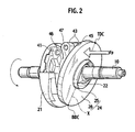
- Fig. 2 is a perspective view of an assembly in that the swash plate and the rotor are mounded to the driving shaft.
- Fig. 3 is an exploded perspective view of the assembly.
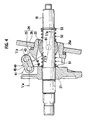
- Fig. 4 is a cross-sectional view of the assembly.
- Fig. 5(a) is a cross-sectional view of the assembly along the line Va-Va in Fig. 4 .
- Fig. 5(b) is a cross-sectional view of the assembly along the line Vb-Vb in Fig. 4 .
- Fig. 6 is a perspective view of an assembly in that the hub of the swash plate is mounded to the sleeve.
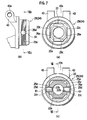
- FIG. 7(a) is a front view of the assembly in that the hub of the swash plate is mounded to the sleeve.
- Fig. 7(b) is a side view of the assembly.
- Fig. 7(c) is a cross-sectional view of the assembly along the line VIIc-VIIc in Fig. 7(b) .
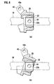
- Figs. 8(a) and 8(b) are cross-sectional views of the assembly along the line VIII-VIII in Fig. 7(c) , wherein Fig. 8(a) shows a condition in that the hub is parallel to the sleeve, and Fig. 8(b) shows a condition in that the hub inclines with respect to the sleeve.
- the linkage mechanism 40 includes a pair of arms 41, 41 that extend from the rotor 21 toward the hub 25 and face each other across a slit 41s, a pair of arms 43, 43 that extend from the hub 25 toward the rotor 21 and face each other across a slit 43s, and a linkage member 45 that is inserted in the slit 41s (between the pair of arms 41, 41) of the rotor 21 and in the slit 43s (between the pair of arms 43, 43) of the swash plate 24.
- the pair of arms 41, 41 and 43, 43 are opposite in an orthogonal direction to the drive shaft 10, that is, a tangential direction of the rotation.
- the width d1 of the slit 41s of the rotor 21, that is, a distance d1 between inner surfaces 41d, 41d of the arms 41, 41 and the width d2 of the slit 43s of the hub 25, that is, a distance d2 between inner surfaces 43d, 43d of the arms 43, 43 are formed the same.
- the width d0 of the linkage member 45, that is, a distance d0 between outer surfaces 45e, 45e of the linkage member is substantially the same as the distances d1 and d2. With this structure, the linkage member 45 is slidably fit in the slits 41s, 43s so as to slidingly contact each other.
- a first end 45a of the linkage member 45 is pivotably attached to the pair of arms 41, 41 of the rotor 21 by a first linking pin 46.
- a second end 45b of the linkage member 45 is pivotably attached to the pair of arms 43, 43 of the swash plate 24 by a second linking pin 47.
- the linking pins 46, 47 are designed to extend in the orthogonal direction to the drive shaft 10, that is a tangential direction of the rotation.
- each the arms 41, 41 of the rotor 21 is formed with a bearing hole 41a in which the first linking pin 46 is rotatably fit.
- the first end 45a of the linkage member 45 is formed with a fixing hole 45c to which the first linking pin 46 is inserted with force and fixed.
- Each arms 43, 43 of the swash plate 24 is formed with a bearing hole 43a to which the second linking pin 47 is rotatably fit.
- the second end 45b of the linkage member 45 has a fixing hole 45d to which the second linking pin 47 is inserted with force and fixed.
- the first linking pin 46 and the second linking pin 47 are made in the same diameter and length.
- the hub 25 is pivotally attached to the sleeve 22 by the pivot pins 61 extending in the orthogonal direction to the drive shaft 10 and pivots as being guided by the tilting guide face 25c, 25e extending in the orthogonal direction to the pivot pin 61.
- the sleeve 22 is formed in a substantially cylindrical shape and is slidably attached to the drives shaft 10 in the axial direction.
- the sleeve 22 is formed with stationary holes 22b and 22b that are coaxially provided on both sides across the driving shaft 10.
- the stationary holes 22b and 22b extend orthogonal to the drive shaft 10 and fix the pivot pins 61 therein.
- the hub 25 of the swash plate is formed with bearing holes 25b and 25b that are coaxially provided on both sides across the driving shaft 10.
- the bearing holes 25b and 25b extend orthogonal to the drive shaft 10.
- the sleeve 22 is attached in a center hole 25c of the hub 25, and the pivot pins 61 and 61 are inserted in the bearing holes 25b and 25b of the hub 25, so that, as shown in Figs. 8(a) and 8(b) , the hub 25 is tiltable with respect to the sleeve 25 about the pivot pins 61.
- the sleeve 22 and the hub 25 are formed with the tilting guide faces 22c, 25e that slidingly contact each other.
- the tilting guide faces 22c, 25e are provided on the both sides across the drive shaft 10 and are orthogonal planes to the pivot pin 61. With this structure, the hub 25 pivots with respect to the sleeve 22 about the pivot pin 61, as being guided by the tilting guide faces 25c, 25e.
- control valve 33 In order to change the amount of the discharge capacity, the control valve 33 is opened or closed. Opening or closing the control valve 33 change the pressure in the crank chamber 5 and the pressure balancing between back of the piston 29 and front of the piston 29 so that the piston stroke is changed.
- the control valve 33 opens the gas supply passage, the high pressure refrigerant gas flows from the discharge chamber 8 into the crank chamber 5 through the gas supply passage, so that the crank chamber pressure Pc increases.
- the crank chamber pressure Pc increases, the inclination angle of the swash plate 24 decreases as the sleeve 22 moves toward the cylinder block 2.
- the piston stroke becomes smaller and the discharging amount decreases.
- the control valve 33 closes the gas supply passage, the refrigerant gas is gradually extracted from the crank chamber 5 to the suction chamber 7 through the gas extraction passage and this causes a reduction in the pressure difference between the crank chamber pressure Pc and the suction chamber pressure Ps.
- the inclination angle of the swash plate 24 increases as the sleeve 22 moves away from the cylinder block 2, so that the piston stroke becomes longer and the discharging mount increases.
- the swash plate 24 When the compressor is operative, the swash plate 24 receives compression reaction force Fp from the piston 29. As shown in Fig. 2 , the compression reaction force Fp can be applied to a position anterior to an upper dead center TDC of the swash plate 24 (i.e., a position where the linkage mechanism is located) in the rotation direction, depending on the rotation speed of the drive shaft 10. This is because the compression reaction force from the piston 29 reaches a maximum value just before the end of the compression stroke of the piston, that is, just before the upper dead center of the piston. In such a case, the swash plate 24 receives the compression reaction force Fp at a position anterior to the dead center TDC in the rotating direction, so that the swash plate 24 receives torsion load.
- the torsion load is received on the tilting guide faces 22c, 25c as well as the link mechanism 40. Few torsion loads is thus given to the linkage mechanism 40 that is a rotary-slide interface configured to transfer a rotary-torque and this results in a reduction of slide friction in the linkage mechanism 40. That is to say, slide friction between the linkage member 45 and the arms 41, 43 is reduced. Concretely, slide friction between the outer surfaces 45e of the linkage member 45 and the inner faces 41d of the arms 41 is reduced and slide friction between the outer surfaces 45e of the linkage member 45 and the inner faces 43d of the arms 43 is reduced. Therefore, the controllability of the compressor is improved.
- the width d4 between a pair of the opposite tilting guide faces 22c, 22c is larger than the width d0 of the first end 45a of the linkage member 45 and the width d0 of the second end 45b of the linkage member 45.
- the present embodiment provides a variable capacity compressor.
- the compressor includes a rotating member 21 fixed to a drive shaft 10 and configured to rotate with the drive shaft 10, a sleeve 22 axially slidably attached to the drive shaft 10, a tilting member 24 tiltably attached to the sleeve 22 by a pivot pin 61, and a linkage mechanism 40 connecting the rotating member 21 with the tilting member 24 and configured to transfer a rotary torque of the rotating member 21 to the tilting member 24 as allowing the tilting member 24 to tilt.
- the sleeve 22 and the tilting member 24 are provided with tilting guide faces 22c, 25d that are formed as orthogonal planes orthogonal to the pivot pin 61 and are configured to slide one another.
- both of the sleeve 22 and the linkage mechanism 40 receive torsion load. This decreases torsion load that is received by the linkage mechanism 40 that is configured to slide as transferring the rotary torque. Therefore, tilt angle of the tilting member 24 is smoothly changed so that controllability of the compressor is improved. In addition, the durability of the linkage mechanism 40 is improved and the linkage mechanism 40 is downsized.
- the linkage mechanism 40 includes an arm 41 extending from a rotating member 21 toward a tilting member 24, and an arm 43 extending from the tilting member 24 toward the rotating member 21 and directly or indirectly pivoted to the arm 41 of the rotating member by a linking pin (in the present embodiment, a first linking pin 46 and a second linking pin 47).
- a linking pin in the present embodiment, a first linking pin 46 and a second linking pin 47.
- the linkage mechanism 40 includes a pair of opposite arms 41 that extend from a rotating member 21 toward a tilting member 24, a pair of opposite arms 43 that extend from the tilting member 24 toward the rotating member21, a linkage member 45 having a first end 45a that is slidably fit between the arms 41 and a second end 45b that is slidably fit between the arms 43, a first linking pin 46 that pivotally connects the first end 45a of the linkage member 45 with the arms 41 of the rotating member, and a second linking pin 47 that pivotally connects the second end 45b of the linkage member 45 with the arms 43 of the tilting member.
- a pair of tilting guides 22c and a pair of the tilting guides 25e are provided on both sides of the driving shaft 10, and a width d4 between the pair of tilting guides 22c of the sleeve 22 is larger than the width d0 between the first end 45a of the linkage member 45 and the width d0 between the second end 45b of the linkage member 45.
- the tilting guide faces 22c of the sleeve 22 receive heavier torsion load and the burden applied to the linkage mechanism 40 is reduced. Therefore, the controllability of the compressor is further improved.
Landscapes
- Engineering & Computer Science (AREA)
- Mechanical Engineering (AREA)
- General Engineering & Computer Science (AREA)
- Manufacturing & Machinery (AREA)
- Compressors, Vaccum Pumps And Other Relevant Systems (AREA)
Abstract
A variable capacity compressor includes a rotating member 21 fixed to a drive shaft 10 so as to rotate with the drive shaft 10, a sleeve 22 axially slidably attached to the drive shaft 10, a tilting member 24 tiltably attached to the sleeve 22 by a pivot pin 61, a linkage mechanism 40 connecting the rotating member 21 with the tilting member 24 and configured to transfer a rotary torque of the rotating member 21 to the tilting member 24 as allowing the tilting member to be tiltable, and a tilting guide face 22c formed on the sleeve 22 and a tilting guide face 25d formed on the tilting member 24 which are formed as planes orthogonal to the pivot pin 61 and are configured to slidingly contact one another.
Description
- The present invention relates to a variable capacity compressor.
- A conventional variable capacity compressor includes a drive shaft, a rotor which is fixed to the drive shaft and rotates integrally with the drive shaft, a sleeve which is axially slidably attached to the drive shaft, a swash plate which is tiltably attached to the sleeve, a link mechanism provided between the rotor and the swash plate to rotate the swash plate together with the rotor, and a piston which reciprocate in response to the rotation of the swash plate (see, for example, Japanese Patent Application Laid-Open Publications No.
2003-172417 10-176658 -
Fig. 9 is a view of a linkage mechanism disclosed in the Publication No. 10-176658. - The linkage mechanism in
Fig. 9 includes a pair ofrotor arms rotor 140 toward aswash plate 141 and are opposed to each other, a singleswash plate arm 147 which extends from theswash plate 141 toward therotor 140, and a pair oflink arms arms rotor 140 is transferred to the swash plate. Thelink arms rotor arms pin 143 and a second end which is rotatably linked to theswash plate arm 147 by a second linkingpin 144. With this, thelink arms pin 143 with respect to therotor arms swash arm 147 rotates about the linkingpin 144 with respect to thelink arms swash plate 141 with respect to a drive shaft (not shown) is changeable. - When the compressor is operative, that is, when the drive shaft rotates, a contact between the
rotor arm 145 and thelink arm 142A and a contact between thelink arm 142A and theswash plate arm 147 function as a torque transferring interface and also as a rotational slide-contact interfaces. In other words, therotor arm 145 and thelink arm 142A rotationally slides with respect to one another under a large pressure of the torque Ft. Thelink arm 142A and theswash plate arm 147 also rotationally slide with respect to one another under a large pressure of the torque Ft. Accordingly, when changing the inclination angle of theswash plate 141, the slide friction at the contact between therotor arm 145 and thelink arm 142A becomes extremely high and the slide friction at the contact between thelink arm 142A and theswash plate arm 147 also becomes extremely high. - And also, when the compressor is operative, that is, when the drive shaft rotates, the
swash plate 141 receives a large compression reaction force Fp from the pistons that are connected to theswash plate 141. As shown inFig. 9 , the compression reaction force Fp can be applied to a position anterior to the linkage mechanism in the rotating direction, depending on the rotation speed (seeFig. 2 ). With this, torsion load is given to theswash plate arm 147 in a direction Y in the figure. Accordingly, thelink 142 gets stuck in theswash plate 141 at two points (C, C) and this causes a further increased slide friction. - To solve the above problem, the Publication No. 2003-172417 has a washer between the rotor arm and the link arm and a washer between the link arm and the swash plate arm, but similar problems are remained.
- The present invention is provided to solve the problem. An object of the present invention is to provide a variable capacity compressor capable of decreasing torsion load applied to a linkage mechanism.
- An aspect of the present invention provides a variable capacity compressor. The variable capacity compressor includes: a rotating member fixed to a drive shaft and configured to rotate integrally with the drive shaft; a sleeve axially slidably attached to the drive shaft; a tilting member tiltably attached to the sleeve by a pivot pin; a linkage mechanism connecting the rotating member with the tilting member and configured to transfer a rotary torque of the rotating member to the tilting member as allowing the tilting member to tilt; a piston configured to reciprocate in response to rotation of the tilting member; and tilting guide faces respectively formed on the sleeve and the tilting member. The tilting guide faces are formed as planes orthogonal to the pivot pin and configured to slide one another.
-
-
Fig. 1 is a cross-sectional view of a variable capacity compressor of a first embodiment according to the present invention; -
Fig. 2 is a perspective view of an assembly in that a swash plate and a rotor are mounded to a driving shaft; -
Fig. 3 is an exploded perspective view of the assembly; -
Fig. 4 is a cross-sectional view of the assembly; -
Fig. 5(a) is a cross-sectional view of the assembly along line Va-Va inFig. 4 , andFig. 5(b) is a cross-sectional view of the assembly along line Vb-Vb inFig. 4 ; -
Fig. 6 is a perspective view of an assembly in that a hub of the swash plate is mounded to a sleeve; -
Figs. 7(a) to 7(c) are views of the assembly in that the hub of the swash plate is mounded to the sleeve, whereinFig. 7(a) is a front view of the assembly,Fig. 7(b) is a side view of the assembly, andFig. 7(c) is a cross-sectional view of the assembly along line VIIc-VIIc inFig. 7(b) ; -
Figs. 8(a) and 8(b) are cross-sectional views of the assembly along line VIII-VIII inFig. 7(c) , whereinFig. 8(a) showing the state in that the hub is parallel to the sleeve, andFig. 8(b) showing a condition in that the hub inclines with respect to the sleeve; and -
Fig. 9 is a cross-sectional view of an example of a conventional linkage mechanism of a variable capacity compressor. - A variable capacity compressor of an embodiment of the present invention will be described with reference to the accompanying drawings.
-
Fig. 1 is a cross-sectional view of the variable capacity compressor. - As shown in
Fig. 1 , the variable capacity compressor 1 of the present embodiment is a swash plate type variable capacity compressor. The variable capacity compressor 1 includes acylinder block 2 having a plurality of cylinder bores 3 (seeFig. 2 ) placed evenly spaced apart in a circumferential direction, afront housing 4 attached to a front end of thecylinder block 2 and defining acrank chamber 5 with thecylinder block 2, and arear housing 6 attached to a rear end of thecylinder block 2 via a valve plate 9 and defining asuction chamber 7 and adischarge chamber 8 therein. Thecylinder block 2, thefront housing 4, and therear housing 6 are fixedly connected to one another by a plurality ofbolts 13 so as to make up a housing of the compressor. - The valve plate 9 is formed with
suction ports 11 that communicate thecylinder bores 3 with thesuction chamber 7, and adischarge ports 12 that communicate thecylinder bores 3 with thedischarge chamber 8. - A suction valve system (not shown) adapted to open or close the
suction ports 11 is attached to the valve plate 9 on the cylinder block side. A discharge valve system (not shown) adapted to open or close thedischarge ports 12 is attached to the valve plate 9 on the rear housing side. A gasket is interposed between the valve plate 9 and therear housing 6 to maintain airtightness of thesuction chamber 7 and thedischarge chamber 8. - A
drive shaft 10 is rotatably supported byradial bearings holes cylinder block 2 and thefront housing 4. With this structure, thedrive shaft 10 is rotatable in thecrank chamber 5. A thrust bearing 20 is interposed between a front face of a later-describedrotor 21 that is fixed to theshaft 10 and an interior face of thefront housing 6. A thrust bearing 16 is interposed between a rear end face of theshaft 10 and anadjustable screw 17 which is a stationary member fixed in the center throughhole 14 of thecylinder block 2. - The
crank chamber 5 accommodates therotor 21, that is a "rotating member", fixed to thedrive shaft 10, asleeve 22 axially slidably attached to thedrive shaft 10, and aswash plate 24, that is a "tilting member", pivotably attached to thesleeve 22 bypivot pins 61. In other words, theswash plate 24 is attached to thedrive shaft 10 via thesleeve 22 andpivot pins 61, so that theswash plate 24 is tiltable with respect to thedrive shaft 10 and is slidable in the axial direction of thedrive shaft 10. In this embodiment, theswash plate 24 includes ahub 25 tiltably attached to thesleeve 22 and aswash plate body 26 fixed to aboss 25a of thehub 25. - Pistons 29 is slidably contained in the
cylinder bore 3, and engaged with theswash plate 24 via a pair of hemispherical-shaped shoes - Between the
rotor 21 as the rotating member and thehub 25 of theswash plate 24 as the tilting member, alinkage mechanism 40 is interposed. Thelinkage mechanism 40 transfers rotary torque from therotor 21 to theswash plate 24 as allowing the inclination angle of theswash plate 24 to change. - When the
sleeve 22 moves toward thecylinder block 2, the inclination angle of theswash plate 24 reduces. On the other hand, when thesleeve 22 moves away from thecylinder block 2, the inclination angle of theswash plate 24 increases.Reference number 53 inFig. 1 represents a stopper such as a c-ring for areturn spring 52. Thestopper 53 is fixed in a circular groove formed on thedrive shaft 10 to support thereturn spring 52 as compressing between thesleeve 22 and thestopper 53. - When the
drive shaft 10 rotates, therotor 21 rotates integrally with thedrive shaft 10. The rotation of therotor 21 is transferred to theswash plate 24 via thelinkage mechanism 40. The rotation of theswash plate 24 is converted into a reciprocating movement of thepistons 29 so that thepistons 29 reciprocate in thecylinder bores 3. By the reciprocating movements of thepistons 29, refrigerant is sucked from thesuction chamber 7 into thecylinder bores 3 through thesuction ports 11 of the valve plate 9, compressed in thecylinder bores 3, and discharged to thedischarge chamber 8 through thedischarge ports 12 of the valve plate 9. - The variable capacity compressor includes a pressure control mechanism. The pressure control mechanism controls a pressure difference (pressure balance) between the crank chamber pressure Pc in back of the
piston 29 and the suction chamber pressure Ps in front of thepiston 29 so as to change the inclination angle of theswash plate 24 to change the piston stroke. When changing the piston stroke, the discharge capacity of the compressor changes. - The pressure control mechanism includes an extraction passage (not shown) that connects and communicates the
crank chamber 5 with thesuction chamber 7, a supply passage (not shown) that connects and communicates thecrank chamber 5 with thedischarge chamber 8, and acontrol valve 33 that is provided in the midstream of the supply passage to open and close the supply passage. - The extraction passage opens regardless of the opening and closing of the
control valve 33, so that the refrigerant gas constantly flows through the extraction passage from thecrank chamber 5 to thesuction chamber 7. - When the
control valve 33 opens the gas supply passage, the refrigerant flows from thedischarge chamber 8 into thecrank chamber 5 through the gas supply passage, and this increases the crank chamber pressure Pc. When the crank chamber pressure Pc increases, the inclination angle of theswash plate 24 decreases as thesleeve 22 moves toward thecylinder block 2. As a result, the piston stroke becomes smaller and the discharging amount decreases. - On the other hand, when the
control valve 33 closes the gas supply passage, the refrigerant is gradually extracted from thecrank chamber 5 to thesuction chamber 7 through the gas extraction passage, and this causes a reduction in the pressure difference between the crank chamber pressure Pc and the suction chamber pressure Ps. As a result, the inclination angle of theswash plate 24 increases as thesleeve 22 moves away from thecylinder block 2, so that the piston strokes become longer and the discharging mount increase. - Next, a supporting structure of the swash plate will be described with reference to
Figs. 2 to 8(b) . -
Fig. 2 is a perspective view of an assembly in that the swash plate and the rotor are mounded to the driving shaft.Fig. 3 is an exploded perspective view of the assembly.Fig. 4 is a cross-sectional view of the assembly.Fig. 5(a) is a cross-sectional view of the assembly along the line Va-Va inFig. 4 .Fig. 5(b) is a cross-sectional view of the assembly along the line Vb-Vb inFig. 4 .Fig. 6 is a perspective view of an assembly in that the hub of the swash plate is mounded to the sleeve.Fig. 7(a) is a front view of the assembly in that the hub of the swash plate is mounded to the sleeve.Fig. 7(b) is a side view of the assembly.Fig. 7(c) is a cross-sectional view of the assembly along the line VIIc-VIIc inFig. 7(b) .Figs. 8(a) and 8(b) are cross-sectional views of the assembly along the line VIII-VIII inFig. 7(c) , whereinFig. 8(a) shows a condition in that the hub is parallel to the sleeve, andFig. 8(b) shows a condition in that the hub inclines with respect to the sleeve. - First, the
linkage mechanism 40 will be described in detail. - As shown in
Figs. 3 ,4 and5(a) , thelinkage mechanism 40 includes a pair ofarms rotor 21 toward thehub 25 and face each other across aslit 41s, a pair ofarms hub 25 toward therotor 21 and face each other across aslit 43s, and alinkage member 45 that is inserted in theslit 41s (between the pair ofarms 41, 41) of therotor 21 and in theslit 43s (between the pair ofarms 43, 43) of theswash plate 24. The pair ofarms drive shaft 10, that is, a tangential direction of the rotation. - The width d1 of the
slit 41s of therotor 21, that is, a distance d1 betweeninner surfaces arms slit 43s of thehub 25, that is, a distance d2 betweeninner surfaces arms linkage member 45, that is, a distance d0 betweenouter surfaces linkage member 45 is slidably fit in theslits - A
first end 45a of thelinkage member 45 is pivotably attached to the pair ofarms rotor 21 by afirst linking pin 46. Asecond end 45b of thelinkage member 45 is pivotably attached to the pair ofarms swash plate 24 by asecond linking pin 47. The linking pins 46, 47 are designed to extend in the orthogonal direction to thedrive shaft 10, that is a tangential direction of the rotation. - In this embodiment, each the
arms rotor 21 is formed with abearing hole 41a in which thefirst linking pin 46 is rotatably fit. Thefirst end 45a of thelinkage member 45 is formed with a fixinghole 45c to which thefirst linking pin 46 is inserted with force and fixed. Eacharms swash plate 24 is formed with abearing hole 43a to which thesecond linking pin 47 is rotatably fit. Thesecond end 45b of thelinkage member 45 has a fixinghole 45d to which thesecond linking pin 47 is inserted with force and fixed. Thefirst linking pin 46 and thesecond linking pin 47 are made in the same diameter and length. - Next, a pivot mechanism connecting the
sleeve 22 with thehub 25 will be described with reference toFigs. 3 to 7 . - The
hub 25 is pivotally attached to thesleeve 22 by the pivot pins 61 extending in the orthogonal direction to thedrive shaft 10 and pivots as being guided by the tiltingguide face pivot pin 61. - The
sleeve 22 is formed in a substantially cylindrical shape and is slidably attached to thedrives shaft 10 in the axial direction. Thesleeve 22 is formed withstationary holes shaft 10. Thestationary holes drive shaft 10 and fix the pivot pins 61 therein. - On the other hand, the
hub 25 of the swash plate is formed with bearing holes 25b and 25b that are coaxially provided on both sides across the drivingshaft 10. The bearing holes 25b and 25b extend orthogonal to thedrive shaft 10. Thesleeve 22 is attached in acenter hole 25c of thehub 25, and the pivot pins 61 and 61 are inserted in the bearing holes 25b and 25b of thehub 25, so that, as shown inFigs. 8(a) and 8(b) , thehub 25 is tiltable with respect to thesleeve 25 about the pivot pins 61. As shown inFigs. 5 to 7 , thesleeve 22 and thehub 25 are formed with the tilting guide faces 22c, 25e that slidingly contact each other. The tilting guide faces 22c, 25e are provided on the both sides across thedrive shaft 10 and are orthogonal planes to thepivot pin 61. With this structure, thehub 25 pivots with respect to thesleeve 22 about thepivot pin 61, as being guided by the tilting guide faces 25c, 25e. - An operation of the compressor of the embodiment will be explained.
- When the
drive shaft 10 rotates, thedrive shaft 10 rotates integrally with therotor 21. The rotation of therotor 21 is transferred to theswash plate 24 via thelinkage mechanism 40. The rotation of theswash plate 24 is converted into a reciprocating movement of thepistons 29 via the pairs ofpiston shoes pistons 29 reciprocate in the cylinder bores 3. By the reciprocating movements of thepistons 29, refrigerant is sucked from thesuction chamber 7 into the cylinder bores 3 through thesuction ports 11 of the valve plate 9, compressed in the cylinder bores 3, and discharged to thedischarge chamber 8 through thedischarge ports 12 of the valve plate 9. - In order to change the amount of the discharge capacity, the
control valve 33 is opened or closed. Opening or closing thecontrol valve 33 change the pressure in thecrank chamber 5 and the pressure balancing between back of thepiston 29 and front of thepiston 29 so that the piston stroke is changed. - More particularly, when the
control valve 33 opens the gas supply passage, the high pressure refrigerant gas flows from thedischarge chamber 8 into thecrank chamber 5 through the gas supply passage, so that the crank chamber pressure Pc increases. When the crank chamber pressure Pc increases, the inclination angle of theswash plate 24 decreases as thesleeve 22 moves toward thecylinder block 2. As a result, the piston stroke becomes smaller and the discharging amount decreases. On the other hand, when thecontrol valve 33 closes the gas supply passage, the refrigerant gas is gradually extracted from thecrank chamber 5 to thesuction chamber 7 through the gas extraction passage and this causes a reduction in the pressure difference between the crank chamber pressure Pc and the suction chamber pressure Ps. As a result, the inclination angle of theswash plate 24 increases as thesleeve 22 moves away from thecylinder block 2, so that the piston stroke becomes longer and the discharging mount increases. - When the compressor is operative, the
swash plate 24 receives compression reaction force Fp from thepiston 29. As shown inFig. 2 , the compression reaction force Fp can be applied to a position anterior to an upper dead center TDC of the swash plate 24 (i.e., a position where the linkage mechanism is located) in the rotation direction, depending on the rotation speed of thedrive shaft 10. This is because the compression reaction force from thepiston 29 reaches a maximum value just before the end of the compression stroke of the piston, that is, just before the upper dead center of the piston. In such a case, theswash plate 24 receives the compression reaction force Fp at a position anterior to the dead center TDC in the rotating direction, so that theswash plate 24 receives torsion load. - In this embodiment, the torsion load is received on the tilting guide faces 22c, 25c as well as the
link mechanism 40. Few torsion loads is thus given to thelinkage mechanism 40 that is a rotary-slide interface configured to transfer a rotary-torque and this results in a reduction of slide friction in thelinkage mechanism 40. That is to say, slide friction between thelinkage member 45 and thearms outer surfaces 45e of thelinkage member 45 and the inner faces 41d of thearms 41 is reduced and slide friction between theouter surfaces 45e of thelinkage member 45 and the inner faces 43d of thearms 43 is reduced. Therefore, the controllability of the compressor is improved. - As shown
Fig. 5 , according to the compressor 1 of this embodiment, the width d4 between a pair of the opposite tilting guide faces 22c, 22c is larger than the width d0 of thefirst end 45a of thelinkage member 45 and the width d0 of thesecond end 45b of thelinkage member 45. With this structure, more torsion load is received at the tilting guide faces 22c, 22c than at thelinkage mechanism 40 so that the controllability of the compressor is further improved. - Here lists characterizations of the present embodiment.
- (1) The present embodiment provides a variable capacity compressor. The compressor includes a rotating
member 21 fixed to adrive shaft 10 and configured to rotate with thedrive shaft 10, asleeve 22 axially slidably attached to thedrive shaft 10, a tiltingmember 24 tiltably attached to thesleeve 22 by apivot pin 61, and alinkage mechanism 40 connecting the rotatingmember 21 with the tiltingmember 24 and configured to transfer a rotary torque of the rotatingmember 21 to the tiltingmember 24 as allowing the tiltingmember 24 to tilt. Thesleeve 22 and the tiltingmember 24 are provided with tilting guide faces 22c, 25d that are formed as orthogonal planes orthogonal to thepivot pin 61 and are configured to slide one another. With this configuration, when theswash plate 24 receives compression reaction force Fp, both of thesleeve 22 and thelinkage mechanism 40 receive torsion load. This decreases torsion load that is received by thelinkage mechanism 40 that is configured to slide as transferring the rotary torque. Therefore, tilt angle of the tiltingmember 24 is smoothly changed so that controllability of the compressor is improved. In addition, the durability of thelinkage mechanism 40 is improved and thelinkage mechanism 40 is downsized. - (2) According to the present embodiment, the
linkage mechanism 40 includes anarm 41 extending from a rotatingmember 21 toward a tiltingmember 24, and anarm 43 extending from the tiltingmember 24 toward the rotatingmember 21 and directly or indirectly pivoted to thearm 41 of the rotating member by a linking pin (in the present embodiment, afirst linking pin 46 and a second linking pin 47). With this structure, when changing the tilt angle of the tiltingmember 24, the components rotate about apivot pin 61 of asleeve 22 or the linking pin (in the present embodiment, the linking pins 46 and 47) of thelinkage mechanism 40. Therefore, the friction is a rolling friction so that friction coefficient is extremely small. The controllability of the compressor is further improved. - (3) According to the present embodiment, the
linkage mechanism 40 includes a pair ofopposite arms 41 that extend from a rotatingmember 21 toward a tiltingmember 24, a pair ofopposite arms 43 that extend from the tiltingmember 24 toward the rotating member21, alinkage member 45 having afirst end 45a that is slidably fit between thearms 41 and asecond end 45b that is slidably fit between thearms 43, afirst linking pin 46 that pivotally connects thefirst end 45a of thelinkage member 45 with thearms 41 of the rotating member, and asecond linking pin 47 that pivotally connects thesecond end 45b of thelinkage member 45 with thearms 43 of the tilting member. With this structure, when changing the tilt angle of the tiltingmember 24, the components rotates about apivot pin 61 of asleeve 22 or the linking pins 46, 47 of thelinkage mechanism 40. Therefore, the friction is a rolling friction so that friction coefficient is extremely small. The controllability of the compressor is further improved. - (4) According to the present embodiment, a pair of tilting guides 22c and a pair of the tilting guides 25e are provided on both sides of the driving
shaft 10, and a width d4 between the pair of tilting guides 22c of thesleeve 22 is larger than the width d0 between thefirst end 45a of thelinkage member 45 and the width d0 between thesecond end 45b of thelinkage member 45. With this structure, the tilting guide faces 22c of thesleeve 22 receive heavier torsion load and the burden applied to thelinkage mechanism 40 is reduced. Therefore, the controllability of the compressor is further improved. - The present invention is not limited to the embodiments described above. The present invention can be implemented with various modifications without departing from technical scope of the present invention.
Claims (4)
- A variable capacity compressor comprising:a rotating member fixed to a drive shaft and configured to rotate integrally with the drive shaft;a sleeve axially slidably attached to the drive shaft;a tilting member tiltably attached to the sleeve by a pivot pin;a linkage mechanism connecting the rotating member with the tilting member and configured to transfer a rotary torque of the rotating member to the tilting member as allowing the tilting member to tilt;a piston configured to reciprocate in response to rotation of the tilting member;tilting guide faces respectively formed on the sleeve and the tilting member, the tilting guide faces formed as planes orthogonal to the pivot pin and configured to slidingly contact one another.
- The variable capacity compressor according to Claim 1, wherein
the linkage mechanism comprising:an arm extending from a rotating member toward the tilting member;an arm extending from the tilting member toward the rotating member; anda linking pin pivotally connecting the arm of the rotating member and the arm of the tilting member directly or indirectly. - The variable capacity compressor according to Claim 1, wherein
the linkage mechanism comprising:a pair of opposite arms extending from the rotating member toward the tilting member;a pair of opposite arms extending from the tilting member toward the rotating member;a linkage member having a first end that is slidably fit between the arms of the rotating member and a second end that is slidably fit between the arms of the tilting member,a first linking pin pivotally connecting the first end of the linkage member and the arms of the rotating member; anda second linking pin pivotally connecting the second end of the linkage member and the arms of the tilting member. - The variable capacity compressor according to Claim 3, wherein
a pair of tilting guides of the sleeve and a pair of the tilting guides of the tilting member are provided on both sides of the driving shaft, and
a width between the pair of tilting guides of the sleeve is larger than a width of the first end of the linkage member and a width of the second end of the linkage member.
Applications Claiming Priority (2)
| Application Number | Priority Date | Filing Date | Title |
|---|---|---|---|
| JP2005313123A JP4794274B2 (en) | 2005-10-27 | 2005-10-27 | Variable capacity compressor |
| PCT/JP2006/320963 WO2007049523A1 (en) | 2005-10-27 | 2006-10-20 | Variable displacement compressor |
Publications (2)
| Publication Number | Publication Date |
|---|---|
| EP1942275A1 true EP1942275A1 (en) | 2008-07-09 |
| EP1942275A4 EP1942275A4 (en) | 2010-08-18 |
Family
ID=37967635
Family Applications (1)
| Application Number | Title | Priority Date | Filing Date |
|---|---|---|---|
| EP06812092A Withdrawn EP1942275A4 (en) | 2005-10-27 | 2006-10-20 | Variable displacement compressor |
Country Status (6)
| Country | Link |
|---|---|
| US (1) | US20090246050A1 (en) |
| EP (1) | EP1942275A4 (en) |
| JP (1) | JP4794274B2 (en) |
| KR (1) | KR20080066928A (en) |
| CN (1) | CN101297115A (en) |
| WO (1) | WO2007049523A1 (en) |
Families Citing this family (7)
| Publication number | Priority date | Publication date | Assignee | Title |
|---|---|---|---|---|
| JP4974927B2 (en) * | 2008-02-26 | 2012-07-11 | カルソニックカンセイ株式会社 | Swash plate compressor |
| JP5065120B2 (en) * | 2008-03-28 | 2012-10-31 | サンデン株式会社 | Reciprocating compressor |
| JP6047306B2 (en) * | 2012-05-28 | 2016-12-21 | サンデンホールディングス株式会社 | Variable capacity compressor |
| JP6063150B2 (en) * | 2012-05-28 | 2017-01-18 | サンデンホールディングス株式会社 | Variable capacity compressor |
| JP6047307B2 (en) * | 2012-05-28 | 2016-12-21 | サンデンホールディングス株式会社 | Variable capacity compressor |
| JP6171875B2 (en) * | 2013-11-13 | 2017-08-02 | 株式会社豊田自動織機 | Variable capacity swash plate compressor |
| KR102680626B1 (en) * | 2018-12-27 | 2024-07-03 | 한온시스템 주식회사 | Swash plate type compressor |
Family Cites Families (18)
| Publication number | Priority date | Publication date | Assignee | Title |
|---|---|---|---|---|
| US4061443A (en) * | 1976-12-02 | 1977-12-06 | General Motors Corporation | Variable stroke compressor |
| US4685866A (en) * | 1985-03-20 | 1987-08-11 | Kabushiki Kaisha Toyoda Jidoshokki Seisakusho | Variable displacement wobble plate type compressor with wobble angle control unit |
| JPH0329586Y2 (en) * | 1985-11-08 | 1991-06-24 | ||
| JPS6365177A (en) * | 1986-09-05 | 1988-03-23 | Hitachi Ltd | Variable displacement swash plate type compressor |
| KR910004933A (en) * | 1989-08-09 | 1991-03-29 | 미다 가쓰시게 | Variable displacement swash plate compressor |
| JP2979687B2 (en) * | 1991-03-26 | 1999-11-15 | 株式会社豊田自動織機製作所 | Variable capacity swash plate compressor |
| JPH08326655A (en) * | 1995-06-05 | 1996-12-10 | Calsonic Corp | Swash plate type compressor |
| JPH10176655A (en) * | 1996-12-13 | 1998-06-30 | Zexel Corp | Variable displacement swash plate compressor |
| JPH10176658A (en) * | 1996-12-17 | 1998-06-30 | Zexel Corp | Variable rocking plate compressor |
| JPH11125176A (en) * | 1997-10-21 | 1999-05-11 | Calsonic Corp | Swash plate type variable displacement compressor |
| JP2000291541A (en) * | 1999-04-06 | 2000-10-17 | Toyota Autom Loom Works Ltd | Design method and manufacturing method of variable displacement compressor |
| JP2001041153A (en) * | 1999-07-23 | 2001-02-13 | Zexel Valeo Climate Control Corp | Variable displacement compressor |
| JP4565367B2 (en) * | 2000-06-07 | 2010-10-20 | 株式会社ヴァレオサーマルシステムズ | Variable capacity swash plate compressor |
| JP2001304103A (en) * | 2001-03-30 | 2001-10-31 | Zexel Valeo Climate Control Corp | Variable displacement compressor |
| DE10124031B4 (en) * | 2001-05-16 | 2009-08-20 | Daimler Ag | Reciprocating engine with a driver |
| JP2003172417A (en) | 2001-12-04 | 2003-06-20 | Sanden Corp | Link mechanism and variable displacement compressor using the same |
| US6899013B2 (en) * | 2003-01-30 | 2005-05-31 | Delphi Technologies, Inc. | Hinge for a variable displacement compressor |
| JP2005083325A (en) * | 2003-09-10 | 2005-03-31 | Toyota Industries Corp | Variable capacity compressor with rotation speed detection mechanism |
-
2005
- 2005-10-27 JP JP2005313123A patent/JP4794274B2/en not_active Expired - Fee Related
-
2006
- 2006-10-20 CN CNA2006800400332A patent/CN101297115A/en active Pending
- 2006-10-20 EP EP06812092A patent/EP1942275A4/en not_active Withdrawn
- 2006-10-20 KR KR1020087009885A patent/KR20080066928A/en not_active Ceased
- 2006-10-20 US US12/091,662 patent/US20090246050A1/en not_active Abandoned
- 2006-10-20 WO PCT/JP2006/320963 patent/WO2007049523A1/en not_active Ceased
Also Published As
| Publication number | Publication date |
|---|---|
| KR20080066928A (en) | 2008-07-17 |
| US20090246050A1 (en) | 2009-10-01 |
| EP1942275A4 (en) | 2010-08-18 |
| JP4794274B2 (en) | 2011-10-19 |
| WO2007049523A1 (en) | 2007-05-03 |
| CN101297115A (en) | 2008-10-29 |
| JP2007120394A (en) | 2007-05-17 |
Similar Documents
| Publication | Publication Date | Title |
|---|---|---|
| US6139283A (en) | Variable capacity swash plate type compressor | |
| US8152483B2 (en) | Variable capacity compressor | |
| US5259736A (en) | Swash plate type compressor with swash plate hinge coupling mechanism | |
| US5615599A (en) | Guiding mechanism for reciprocating piston of piston-type compressor | |
| CA1332595C (en) | Starting displacement setting device in variable displacement compressor | |
| EP0809024A1 (en) | Reciprocating pistons of piston type compressor | |
| JPH10266952A (en) | Variable displacement swash plate compressor | |
| US20090246050A1 (en) | Variable capacity compressor | |
| US20070220859A1 (en) | Link Mechanism and Variable Displacement Compressor | |
| US7972118B2 (en) | Variable capacity compressor | |
| JPH10196525A (en) | Swash plate compressor | |
| KR100282042B1 (en) | Variable capacity swash plate compressor | |
| US5517900A (en) | Tiltable swash plate type compressor | |
| EP2063121A1 (en) | Variable displacement compressor | |
| EP0338761A2 (en) | Control cylinder device in variable displacement compressor | |
| JP4451323B2 (en) | Link mechanism and variable capacity compressor using the same | |
| KR100558704B1 (en) | Variable capacity swash plate compressor | |
| EP1039128A2 (en) | Swash plate type compressor | |
| KR100558705B1 (en) | Variable capacity swash plate compressor | |
| JP3183461B2 (en) | Assembling method of variable capacity swash plate type compressor | |
| JP2015063892A (en) | Variable displacement swash plate compressor | |
| JPH03179175A (en) | Axial piston device | |
| JPH02283874A (en) | Swash plate type variable capacity compressor | |
| JP2000170652A (en) | Variable displacement swash plate compressor | |
| KR20020045038A (en) | Variable capacity swash plate type compressor |
Legal Events
| Date | Code | Title | Description |
|---|---|---|---|
| PUAI | Public reference made under article 153(3) epc to a published international application that has entered the european phase |
Free format text: ORIGINAL CODE: 0009012 |
|
| 17P | Request for examination filed |
Effective date: 20080423 |
|
| AK | Designated contracting states |
Kind code of ref document: A1 Designated state(s): DE FR GB |
|
| DAX | Request for extension of the european patent (deleted) | ||
| RBV | Designated contracting states (corrected) |
Designated state(s): DE FR GB |
|
| A4 | Supplementary search report drawn up and despatched |
Effective date: 20100715 |
|
| 17Q | First examination report despatched |
Effective date: 20110418 |
|
| STAA | Information on the status of an ep patent application or granted ep patent |
Free format text: STATUS: THE APPLICATION IS DEEMED TO BE WITHDRAWN |
|
| 18D | Application deemed to be withdrawn |
Effective date: 20120118 |