EP1942254A2 - Methods and apparatus for fabricating a fan assembly for use with turbine engines - Google Patents
Methods and apparatus for fabricating a fan assembly for use with turbine engines Download PDFInfo
- Publication number
- EP1942254A2 EP1942254A2 EP07123440A EP07123440A EP1942254A2 EP 1942254 A2 EP1942254 A2 EP 1942254A2 EP 07123440 A EP07123440 A EP 07123440A EP 07123440 A EP07123440 A EP 07123440A EP 1942254 A2 EP1942254 A2 EP 1942254A2
- Authority
- EP
- European Patent Office
- Prior art keywords
- casing
- rotor
- fan
- bladeout
- fan assembly
- Prior art date
- Legal status (The legal status is an assumption and is not a legal conclusion. Google has not performed a legal analysis and makes no representation as to the accuracy of the status listed.)
- Withdrawn
Links
Images

Classifications
-
- F—MECHANICAL ENGINEERING; LIGHTING; HEATING; WEAPONS; BLASTING
- F01—MACHINES OR ENGINES IN GENERAL; ENGINE PLANTS IN GENERAL; STEAM ENGINES
- F01D—NON-POSITIVE DISPLACEMENT MACHINES OR ENGINES, e.g. STEAM TURBINES
- F01D21/00—Shutting-down of machines or engines, e.g. in emergency; Regulating, controlling, or safety means not otherwise provided for
- F01D21/04—Shutting-down of machines or engines, e.g. in emergency; Regulating, controlling, or safety means not otherwise provided for responsive to undesired position of rotor relative to stator or to breaking-off of a part of the rotor, e.g. indicating such position
- F01D21/045—Shutting-down of machines or engines, e.g. in emergency; Regulating, controlling, or safety means not otherwise provided for responsive to undesired position of rotor relative to stator or to breaking-off of a part of the rotor, e.g. indicating such position special arrangements in stators or in rotors dealing with breaking-off of part of rotor
-
- F—MECHANICAL ENGINEERING; LIGHTING; HEATING; WEAPONS; BLASTING
- F01—MACHINES OR ENGINES IN GENERAL; ENGINE PLANTS IN GENERAL; STEAM ENGINES
- F01D—NON-POSITIVE DISPLACEMENT MACHINES OR ENGINES, e.g. STEAM TURBINES
- F01D11/00—Preventing or minimising internal leakage of working-fluid, e.g. between stages
- F01D11/08—Preventing or minimising internal leakage of working-fluid, e.g. between stages for sealing space between rotor blade tips and stator
- F01D11/12—Preventing or minimising internal leakage of working-fluid, e.g. between stages for sealing space between rotor blade tips and stator using a rubstrip, e.g. erodible. deformable or resiliently-biased part
- F01D11/122—Preventing or minimising internal leakage of working-fluid, e.g. between stages for sealing space between rotor blade tips and stator using a rubstrip, e.g. erodible. deformable or resiliently-biased part with erodable or abradable material
-
- F—MECHANICAL ENGINEERING; LIGHTING; HEATING; WEAPONS; BLASTING
- F01—MACHINES OR ENGINES IN GENERAL; ENGINE PLANTS IN GENERAL; STEAM ENGINES
- F01D—NON-POSITIVE DISPLACEMENT MACHINES OR ENGINES, e.g. STEAM TURBINES
- F01D5/00—Blades; Blade-carrying members; Heating, heat-insulating, cooling or antivibration means on the blades or the members
- F01D5/12—Blades
- F01D5/14—Form or construction
- F01D5/20—Specially-shaped blade tips to seal space between tips and stator
-
- F—MECHANICAL ENGINEERING; LIGHTING; HEATING; WEAPONS; BLASTING
- F02—COMBUSTION ENGINES; HOT-GAS OR COMBUSTION-PRODUCT ENGINE PLANTS
- F02K—JET-PROPULSION PLANTS
- F02K3/00—Plants including a gas turbine driving a compressor or a ducted fan
- F02K3/02—Plants including a gas turbine driving a compressor or a ducted fan in which part of the working fluid by-passes the turbine and combustion chamber
- F02K3/04—Plants including a gas turbine driving a compressor or a ducted fan in which part of the working fluid by-passes the turbine and combustion chamber the plant including ducted fans, i.e. fans with high volume, low pressure outputs, for augmenting the jet thrust, e.g. of double-flow type
- F02K3/06—Plants including a gas turbine driving a compressor or a ducted fan in which part of the working fluid by-passes the turbine and combustion chamber the plant including ducted fans, i.e. fans with high volume, low pressure outputs, for augmenting the jet thrust, e.g. of double-flow type with front fan
-
- F—MECHANICAL ENGINEERING; LIGHTING; HEATING; WEAPONS; BLASTING
- F04—POSITIVE - DISPLACEMENT MACHINES FOR LIQUIDS; PUMPS FOR LIQUIDS OR ELASTIC FLUIDS
- F04D—NON-POSITIVE-DISPLACEMENT PUMPS
- F04D29/00—Details, component parts, or accessories
- F04D29/40—Casings; Connections of working fluid
- F04D29/52—Casings; Connections of working fluid for axial pumps
- F04D29/522—Casings; Connections of working fluid for axial pumps especially adapted for elastic fluid pumps
-
- F—MECHANICAL ENGINEERING; LIGHTING; HEATING; WEAPONS; BLASTING
- F05—INDEXING SCHEMES RELATING TO ENGINES OR PUMPS IN VARIOUS SUBCLASSES OF CLASSES F01-F04
- F05D—INDEXING SCHEME FOR ASPECTS RELATING TO NON-POSITIVE-DISPLACEMENT MACHINES OR ENGINES, GAS-TURBINES OR JET-PROPULSION PLANTS
- F05D2220/00—Application
- F05D2220/30—Application in turbines
- F05D2220/36—Application in turbines specially adapted for the fan of turbofan engines
-
- F—MECHANICAL ENGINEERING; LIGHTING; HEATING; WEAPONS; BLASTING
- F05—INDEXING SCHEMES RELATING TO ENGINES OR PUMPS IN VARIOUS SUBCLASSES OF CLASSES F01-F04
- F05D—INDEXING SCHEME FOR ASPECTS RELATING TO NON-POSITIVE-DISPLACEMENT MACHINES OR ENGINES, GAS-TURBINES OR JET-PROPULSION PLANTS
- F05D2300/00—Materials; Properties thereof
- F05D2300/60—Properties or characteristics given to material by treatment or manufacturing
- F05D2300/603—Composites; e.g. fibre-reinforced
-
- F—MECHANICAL ENGINEERING; LIGHTING; HEATING; WEAPONS; BLASTING
- F05—INDEXING SCHEMES RELATING TO ENGINES OR PUMPS IN VARIOUS SUBCLASSES OF CLASSES F01-F04
- F05D—INDEXING SCHEME FOR ASPECTS RELATING TO NON-POSITIVE-DISPLACEMENT MACHINES OR ENGINES, GAS-TURBINES OR JET-PROPULSION PLANTS
- F05D2300/00—Materials; Properties thereof
- F05D2300/60—Properties or characteristics given to material by treatment or manufacturing
- F05D2300/615—Filler
-
- Y—GENERAL TAGGING OF NEW TECHNOLOGICAL DEVELOPMENTS; GENERAL TAGGING OF CROSS-SECTIONAL TECHNOLOGIES SPANNING OVER SEVERAL SECTIONS OF THE IPC; TECHNICAL SUBJECTS COVERED BY FORMER USPC CROSS-REFERENCE ART COLLECTIONS [XRACs] AND DIGESTS
- Y02—TECHNOLOGIES OR APPLICATIONS FOR MITIGATION OR ADAPTATION AGAINST CLIMATE CHANGE
- Y02T—CLIMATE CHANGE MITIGATION TECHNOLOGIES RELATED TO TRANSPORTATION
- Y02T50/00—Aeronautics or air transport
- Y02T50/60—Efficient propulsion technologies, e.g. for aircraft
-
- Y—GENERAL TAGGING OF NEW TECHNOLOGICAL DEVELOPMENTS; GENERAL TAGGING OF CROSS-SECTIONAL TECHNOLOGIES SPANNING OVER SEVERAL SECTIONS OF THE IPC; TECHNICAL SUBJECTS COVERED BY FORMER USPC CROSS-REFERENCE ART COLLECTIONS [XRACs] AND DIGESTS
- Y10—TECHNICAL SUBJECTS COVERED BY FORMER USPC
- Y10T—TECHNICAL SUBJECTS COVERED BY FORMER US CLASSIFICATION
- Y10T29/00—Metal working
- Y10T29/49—Method of mechanical manufacture
- Y10T29/49316—Impeller making
Definitions
- This invention relates generally to turbine engines and, more particularly, to methods and apparatus for fabricating a fan assembly for use with a turbine engine.
- At least some known turbine engines include a fan assembly that channels air to a compressor.
- Known fan assemblies include a plurality of fan blades that extend radially outward from a rotor shaft.
- the rotor shaft has an axis of rotation that passes through a center of gravity of the fan assembly.
- the rotor rotates about the axis of rotation within an orbiting diameter.
- the orbiting diameter is configured to be minimized during normal engine operations.
- a fragment of a fan blade may become separated from the remainder of the blade and/or the blade may become separated from the rotor. This is commonly referred to as a "bladeout".
- bladeout When such damage occurs, a substantial rotary unbalance load may be created within the damaged fan assembly that may cause the orbiting diameter of the rotor to increase. As a result, the remaining intact fan blades may contact the surrounding fan assembly casing, which, over time, may cause damage to such blades and/or the casing.
- At least some known fan assemblies include a filler material that is applied to the fan casing.
- the filler material facilitates reducing a gap defined between the tips of the fan blades and the fan casing.
- Known filler materials are typically made from a composite material that erodes when contacted by a fan blade. Accordingly, during a bladeout, at least one fan blade may cause the filler material to erode, such that a sufficient gap is defined between the remaining fan blades and the casing.
- the increased gap facilitates accommodating the increased orbiting diameter of the rotor. By freely accommodating the orbiting of the rotor, the rotorary unbalance forces transmitted to the rest of the engine are reduced.
- at least some known filler materials increase the overall weight of the engine enough that the filler material weight may actually decrease engine efficiency and/or increase costs associated with engine fabrication, assembly, and/or maintenance.
- a method for fabricating a fan assembly includes providing a rotor having a plurality of rotor blades. At least one rotor blade is fabricated from a frangible material. The method also includes coupling a casing substantially circumferentially about the rotor, and positioning the casing a distance from the plurality of rotor blades. The distance is selected to facilitate increasing an amount of initial resistance created between the casing and the plurality of rotor blades after a bladeout.
- a fan assembly in a further aspect, includes a rotor including a plurality of rotor blades. At least one rotor blade is fabricated from a frangible material.
- the fan assembly also includes a casing extending circumferentially about the rotor. The casing is positioned a pre-selected distance from the plurality of rotor blades. The distance facilitates increasing an amount of initial resistance created between the casing and the plurality of rotor blades after a bladeout.
- a turbine engine in another aspect, includes a fan assembly configured to channel air to a compressor.
- the fan assembly includes a rotor including a plurality of rotor blades. At least one rotor blade is fabricated from a frangible material.
- the fan assembly also includes a casing extending circumferentially about the rotor. The casing is positioned a pre-selected distance from the plurality of rotor blades. The distance facilitates increasing an amount of initial resistance created between the casing and the plurality of rotor blades after a bladeout to facilitate eroding the at least one rotor blade fabricated from a frangible material when the at least one rotor blade contacts the casing after the bladeout.
- a fan assembly includes a rotor including a plurality of rotor blades, and a casing that is coupled circumferentially around the plurality of rotor blades.
- the fan blades are fabricated from a frangible composite material.
- the casing is positioned a pre-determined distance from the plurality of rotor blades, wherein the distance is selected to facilitate increasing a resistance between the casing and the plurality of rotor blades after a bladeout.
- an increased initial resistance created between the casing and the fan blades causes erosion of the fan blades after a bladeout.
- the erosion of the fan blades facilitates reducing a radial rub force imparted by the fan blades on to the fan case and allows the rotor to orbit at a substantially larger orbit diameter.
- bladeout refers to the separation of a fragment of a fan blade and/or the separation of a blade from the rotor during engine operation.
- the present invention provides a filler material that is applied to the fan casing. More specifically, an amount of filler material applied to the casing is reduced, in comparison to an amount used with known fan assemblies. As such, the exemplary embodiments provide a filler material that creates a greater resistance between the fan casing and the fan blade. Further, the reduced amount of filler material facilitates reducing an overall weight of the fan assembly and, therefore, reducing an overall weight of the engine.
- FIG. 1 is a schematic illustration of an exemplary engine assembly 10 having a longitudinal axis 12.
- Engine assembly 10 includes a fan assembly 14, a core gas turbine engine 16 that is disposed downstream from fan assembly 14, and a low-pressure turbine 18 that is disposed downstream from core gas turbine engine 16.
- Core gas turbine engine 16 includes a high-pressure compressor 22, a combustor 24, and a high-pressure turbine 26.
- Fan assembly 14 includes a plurality of fan blades 28 that extend radially outward from a rotor disk 30 of a rotor 31, and a fan casing 32 that extends circumferentially about fan blades 28.
- a tip 34 of each fan blade 28 is positioned a radial distance D 1 from fan casing 32.
- distance D 1 is selected to facilitate reducing an amount of air that passes over tips 34, i.e. tip spillage.
- Engine assembly 10 has an intake side 36 and an exhaust side 38. Compressor 22 and high-pressure turbine 26 are coupled together by a second drive shaft 40.
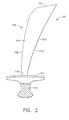
- FIG 2 is an exemplary embodiment of a fan blade 28.
- Fan blade 28 includes an airfoil 100 and an integral dovetail 102 that is used for mounting each fan blade 28 to a rotor disk, such as rotor disk 30 (shown in Figure 1 ).
- Each fan blade 28 includes a first contoured sidewall 104 and a second contoured sidewall 106.
- first sidewall 104 is convex and defines a suction side of fan blade 28
- second sidewall 106 is concave and defines a pressure side of fan blade 28.
- Sidewalls 104 and 106 are joined together at a leading edge 108 and at an axially-spaced trailing edge 110 of fan blade 28.
- airfoil trailing edge 110 is spaced chordwise and downstream from airfoil leading edge 108.
- First and second sidewalls 104 and 106 respectively, extend longitudinally or radially outward in span from a blade root 112 positioned adjacent dovetail 102, to airfoil or blade tip 34.
- a dovetail platform 116 is positioned at blade root 112 and extends radially outward from first and second sidewalls 104 and 106, respectively.
- the general configuration of each fan blade 28 may take any conventional form, with or without platform 116 or dovetail 102.
- fan blade 28 may be formed integrally with disk 30 in a blisk-type configuration that does not include dovetail 102.
- fan blade 28 is fabricated from a frangible composite material.
- the frangible composite material facilitates erosion of fan blade 28.
- fan blade 28 is configured to erode if contacted by casing 32.
- a portion of remaining blades 28 extending from disk 30 may begin to erode.
- an unbalance of rotor 31 causes rotor disk 30 to rotate with a greater orbiting diameter in comparison to normal operating conditions.
- the greater orbiting diameter may cause intact blades 28 extending from rotor disk 30 to contact fan casing 32.
- a resistance between the intact blades 28 and fan casing 32 may cause erosion of fan blade tips 34.
- rotor disk 30 rotates within an orbiting diameter that is substantially smaller than after a bladeout, and is centered about longitudinal axis 12. Accordingly, fan blades 28 rotate about longitudinal axis 12, while maintaining distance D 1 from fan casing 32 with the exception of minor variations due to small engine 10 imbalances. Distance D 1 facilitates substantially reducing an amount of air that may be channeled past tips 34 during engine operation. As such, an amount of air channeled to compressor 22 is facilitated to be increased.
- fan blade 28 may be damaged and a bladeout event may occur.
- a bladeout event initiates an engine shutdown sequence.
- an imbalance of engine 10 will likely be induced such that rotor 31 deflects out of orbit causing an increase in the orbiting diameter of rotor disk 30.
- Such a deflection may be of sufficient magnitude to facilitate at least one other blade on the opposite side of the rotor from the initial release blade, 28 to impact casing 32 and lose material, thereby reducing the net unbalance.
- a resistance created between fan casing 32 and the blade 28 is initially increased. Because blades 28 are fabricated from a frangible material, blades 28 are facilitated to erode more quickly and reduce the resulting radial load by effectively increasing distance D 1 by erosion of the blade tips.
- casing 32 is oriented to initially increase the resistance between intact fan blades 28 and casing 32.
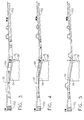
- Figure 3 is a view of a fan casing 32 including a filler material 150.
- Figure 4 is a view of an alternative embodiment of fan casing 32 including filler material 150.
- Figure 5 is a view of fan casing 32 having no filler material 150.
- a filler material 150 is applied to casing 32 to enable fan assembly 14 to accommodate a greater rotor orbiting diameter after a bladeout.
- filler material 150 is fabricated from a frangible material that erodes when in contact with a fan blade 28. As such, during normal engine operations, filler material 150 facilitates reducing the distance D 1 between the tips 34 of fan blades 28 and casing 32, such that air flow through fan blades 28 is facilitated to be increased. Moreover, during a bladeout, filler material 150 erodes when contacted by fan blades 28 to facilitate accommodating for the increased orbiting diameter of the rotor.
- filler material 150 is a honeycomb adhesively bonded to casing 32.
- filler material is fabricated from at least one of a composite and aluminum. In an alternative embodiment, filler material is any material capable of functioning, as described herein.
- an amount of filler material 150 applied to casing 32 is reduced, in comparison to known fan assemblies.
- the reduced amount of filler material 150 enables casing 32 to be positioned in closer proximity to fan blades 28 than is generally possible with known fan assemblies. More specifically, the distance D 1 defined between fan casing 32 and fan blades 28 is reduced, in comparison to known fan assemblies.
- the reduced amount of filler material 150 also facilitates reducing damping within filler material 150.
- the reduced damping of filler material 150 facilitates increasing the resistance created between casing 32 and fan blades 28 to a level of resistance that is substantially equivalent to the resistance created by casing 32 when fan blades 28 contact casing 32. Accordingly, the resistance of filler material 150 facilitates the erosion of fan blades 28, as described above.
- casing 32 does not include filler material 150. Rather, casing 32 is positioned at a distance D 1 that facilitates fan assembly 14 operating under normal engine operating conditions, but during a bladeout, the distance D 1 causes contact between casing 32 and intact fan blades 28. In such an embodiment, casing 32 resists fan blades 28 causing erosion of fan blades 28, as described above.
- the fan casings 32 described in Figures 3-5 facilitate reducing a weight of fan assembly 14, in comparison to known fan assemblies.
- a weight of fan assembly 14 is reduced between approximately twenty-one pounds and approximately seventy pounds, in comparison to known fan assemblies.
- the exemplary embodiments described in Figures 3 and 4 enable less acoustic panels 152 to be used, such that a weight of fan assembly 14 is further reduced between approximately six pounds and approximately eleven pounds, in comparison to known fan assemblies.
- the exemplary embodiments described in Figures 3 and 4 facilitate reducing a weight of engine 10 between approximately twenty-seven pounds and approximately eighty-one pounds, in comparison to known fan assemblies.
- the exemplary embodiment described in Figure 5 facilitates reducing a weight of fan assembly 14 by approximately ninety-four pounds, in comparison to known fan assemblies which include filler material. Further, the embodiment described in Figure 5 also enables less acoustic panels to be used, such that a weight of fan assembly 14 is further reduced by approximately eighteen pounds, in comparison to known fan assemblies. As such, the exemplary embodiment described in Figure 5 facilitates reducing a weight of engine 10 by approximately one hundred twelve pounds, in comparison to known fan assemblies.
- the exemplary embodiments of fan casing 32 described in Figures 3-5 facilitate reducing an overall weight of engine 10 in comparison to known engines.
- the described embodiments facilitate increasing an efficiency of engine 10 in comparison to known engines.
- the described embodiments facilitate decreasing costs associated with fabrication, assembly, and/or maintenance of engine 10.
- a method for fabricating a fan assembly includes providing a rotor having a plurality of rotor blades. At least one rotor blade is fabricated from a frangible material. The method also includes coupling a casing substantially circumferentially about the rotor, and positioning the casing a distance from the plurality of rotor blades. The distance is selected to facilitate increasing an amount of initial resistance created between the casing and the plurality of rotor blades after a bladeout.
- the present invention provides a method and system for accommodating an increased rotor orbiting diameter. Specifically, by increasing an initial resistance of the casing to the frangible blades, the frangible blades are enabled to erode thereby providing a sufficient distance between the blades and the casing. Moreover, by reducing a weight of filler material, an overall weight of engine 10 is reduced. Accordingly, an operating efficiency of an aircraft is facilitated to be increased. In addition, costs associated with fabricating, assembling, and/or maintaining engine 10 are facilitated to be reduced.
Landscapes
- Engineering & Computer Science (AREA)
- Mechanical Engineering (AREA)
- General Engineering & Computer Science (AREA)
- Chemical & Material Sciences (AREA)
- Combustion & Propulsion (AREA)
- Structures Of Non-Positive Displacement Pumps (AREA)
Abstract
Description
- This invention relates generally to turbine engines and, more particularly, to methods and apparatus for fabricating a fan assembly for use with a turbine engine.
- At least some known turbine engines include a fan assembly that channels air to a compressor. Known fan assemblies include a plurality of fan blades that extend radially outward from a rotor shaft. The rotor shaft has an axis of rotation that passes through a center of gravity of the fan assembly. During normal operations, the rotor rotates about the axis of rotation within an orbiting diameter. Generally, the orbiting diameter is configured to be minimized during normal engine operations.
- During operation of the engine, a fragment of a fan blade may become separated from the remainder of the blade and/or the blade may become separated from the rotor. This is commonly referred to as a "bladeout". When such damage occurs, a substantial rotary unbalance load may be created within the damaged fan assembly that may cause the orbiting diameter of the rotor to increase. As a result, the remaining intact fan blades may contact the surrounding fan assembly casing, which, over time, may cause damage to such blades and/or the casing.
- At least some known fan assemblies include a filler material that is applied to the fan casing. The filler material facilitates reducing a gap defined between the tips of the fan blades and the fan casing. Known filler materials are typically made from a composite material that erodes when contacted by a fan blade. Accordingly, during a bladeout, at least one fan blade may cause the filler material to erode, such that a sufficient gap is defined between the remaining fan blades and the casing. The increased gap facilitates accommodating the increased orbiting diameter of the rotor. By freely accommodating the orbiting of the rotor, the rotorary unbalance forces transmitted to the rest of the engine are reduced. However, at least some known filler materials increase the overall weight of the engine enough that the filler material weight may actually decrease engine efficiency and/or increase costs associated with engine fabrication, assembly, and/or maintenance.
- In one aspect, a method for fabricating a fan assembly is provided, wherein the method includes providing a rotor having a plurality of rotor blades. At least one rotor blade is fabricated from a frangible material. The method also includes coupling a casing substantially circumferentially about the rotor, and positioning the casing a distance from the plurality of rotor blades. The distance is selected to facilitate increasing an amount of initial resistance created between the casing and the plurality of rotor blades after a bladeout.
- In a further aspect, a fan assembly includes a rotor including a plurality of rotor blades. At least one rotor blade is fabricated from a frangible material. The fan assembly also includes a casing extending circumferentially about the rotor. The casing is positioned a pre-selected distance from the plurality of rotor blades. The distance facilitates increasing an amount of initial resistance created between the casing and the plurality of rotor blades after a bladeout.
- In another aspect, a turbine engine includes a fan assembly configured to channel air to a compressor. The fan assembly includes a rotor including a plurality of rotor blades. At least one rotor blade is fabricated from a frangible material. The fan assembly also includes a casing extending circumferentially about the rotor. The casing is positioned a pre-selected distance from the plurality of rotor blades. The distance facilitates increasing an amount of initial resistance created between the casing and the plurality of rotor blades after a bladeout to facilitate eroding the at least one rotor blade fabricated from a frangible material when the at least one rotor blade contacts the casing after the bladeout.
- Embodiments of the present invention will now be described, by way of example only, with reference to the accompanying drawings, in which:
-
Figure 1 is a schematic illustration of an exemplary turbine engine; -
Figure 2 is a side view of an exemplary fan blade that may be used with the engine shown inFigure 1 ; -
Figure 3 is an enlarged schematic view of a portion of an exemplary fan casing that may be used with the engine shown inFigure 1 ; -
Figure 4 is an enlarged schematic view of an alternative embodiment of the fan casing shown inFigure 3 ; and -
Figure 5 is an enlarged schematic view of another alternative embodiment of the fan casing shown inFigure 3 . - The present invention provides an exemplary method and system for fabricating a fan assembly for an engine. Specifically, in the exemplary embodiment, a fan assembly is provided that includes a rotor including a plurality of rotor blades, and a casing that is coupled circumferentially around the plurality of rotor blades. In the exemplary embodiment, the fan blades are fabricated from a frangible composite material. Moreover, in the exemplary embodiment, the casing is positioned a pre-determined distance from the plurality of rotor blades, wherein the distance is selected to facilitate increasing a resistance between the casing and the plurality of rotor blades after a bladeout. Specifically, an increased initial resistance created between the casing and the fan blades causes erosion of the fan blades after a bladeout. The erosion of the fan blades facilitates reducing a radial rub force imparted by the fan blades on to the fan case and allows the rotor to orbit at a substantially larger orbit diameter. As used herein, the term "bladeout" refers to the separation of a fragment of a fan blade and/or the separation of a blade from the rotor during engine operation.
- Moreover, the present invention provides a filler material that is applied to the fan casing. More specifically, an amount of filler material applied to the casing is reduced, in comparison to an amount used with known fan assemblies. As such, the exemplary embodiments provide a filler material that creates a greater resistance between the fan casing and the fan blade. Further, the reduced amount of filler material facilitates reducing an overall weight of the fan assembly and, therefore, reducing an overall weight of the engine.
- Although the present invention is described below in reference to its application in connection with the turbine engine shown in
Figure 1 , it should be apparent to those skilled in the art and guided by the teachings herein provided that with appropriate modification, the system and methods of the present invention can also be suitable for any engine capable of operating as described herein, including, for example, a steam turbine engine. - Moreover, although the present invention is described below in reference to its application in connection with fan assemblies, it should be apparent to those skilled in the art and guided by the teachings herein provided that, with appropriate modification, the system and methods of the present invention can also be suitable for use with any assembly having a rotor.
-
Figure 1 is a schematic illustration of anexemplary engine assembly 10 having alongitudinal axis 12.Engine assembly 10 includes afan assembly 14, a coregas turbine engine 16 that is disposed downstream fromfan assembly 14, and a low-pressure turbine 18 that is disposed downstream from coregas turbine engine 16. Coregas turbine engine 16 includes a high-pressure compressor 22, acombustor 24, and a high-pressure turbine 26. -
Fan assembly 14 includes a plurality offan blades 28 that extend radially outward from arotor disk 30 of arotor 31, and afan casing 32 that extends circumferentially aboutfan blades 28. Atip 34 of eachfan blade 28 is positioned a radial distance D1 fromfan casing 32. In the exemplary embodiment, distance D1 is selected to facilitate reducing an amount of air that passes overtips 34, i.e. tip spillage.Engine assembly 10 has anintake side 36 and anexhaust side 38.Compressor 22 and high-pressure turbine 26 are coupled together by asecond drive shaft 40. -
Figure 2 is an exemplary embodiment of afan blade 28.Fan blade 28 includes anairfoil 100 and anintegral dovetail 102 that is used for mounting eachfan blade 28 to a rotor disk, such as rotor disk 30 (shown inFigure 1 ). Eachfan blade 28 includes a firstcontoured sidewall 104 and a secondcontoured sidewall 106. In the exemplary embodiment,first sidewall 104 is convex and defines a suction side offan blade 28, andsecond sidewall 106 is concave and defines a pressure side offan blade 28.Sidewalls leading edge 108 and at an axially-spacedtrailing edge 110 offan blade 28. More specifically,airfoil trailing edge 110 is spaced chordwise and downstream fromairfoil leading edge 108. First andsecond sidewalls blade root 112 positionedadjacent dovetail 102, to airfoil orblade tip 34. Adovetail platform 116 is positioned atblade root 112 and extends radially outward from first andsecond sidewalls fan blade 28 may take any conventional form, with or withoutplatform 116 ordovetail 102. For example,fan blade 28 may be formed integrally withdisk 30 in a blisk-type configuration that does not includedovetail 102. - In the exemplary embodiment,
fan blade 28 is fabricated from a frangible composite material. The frangible composite material facilitates erosion offan blade 28. Specifically,fan blade 28 is configured to erode if contacted by casing 32. As such, after a bladeout, a portion of remainingblades 28 extending fromdisk 30 may begin to erode. Specifically, after a bladeout, an unbalance ofrotor 31 causesrotor disk 30 to rotate with a greater orbiting diameter in comparison to normal operating conditions. The greater orbiting diameter may causeintact blades 28 extending fromrotor disk 30 to contactfan casing 32. Resultantly, a resistance between theintact blades 28 andfan casing 32 may cause erosion offan blade tips 34. - During normal engine operations,
rotor disk 30 rotates within an orbiting diameter that is substantially smaller than after a bladeout, and is centered aboutlongitudinal axis 12. Accordingly,fan blades 28 rotate aboutlongitudinal axis 12, while maintaining distance D1 fromfan casing 32 with the exception of minor variations due tosmall engine 10 imbalances. Distance D1 facilitates substantially reducing an amount of air that may be channeled pasttips 34 during engine operation. As such, an amount of air channeled tocompressor 22 is facilitated to be increased. - In the event that a foreign object impacts at least one
fan blade 28,fan blade 28 may be damaged and a bladeout event may occur. Typically, a bladeout event initiates an engine shutdown sequence. Moreover, in such an event, an imbalance ofengine 10 will likely be induced such thatrotor 31 deflects out of orbit causing an increase in the orbiting diameter ofrotor disk 30. Such a deflection may be of sufficient magnitude to facilitate at least one other blade on the opposite side of the rotor from the initial release blade, 28 toimpact casing 32 and lose material, thereby reducing the net unbalance. Specifically, a resistance created between fan casing 32 and theblade 28 is initially increased. Becauseblades 28 are fabricated from a frangible material,blades 28 are facilitated to erode more quickly and reduce the resulting radial load by effectively increasing distance D1 by erosion of the blade tips. - Further, in the
exemplary embodiment casing 32 is oriented to initially increase the resistance betweenintact fan blades 28 andcasing 32. Specifically,Figure 3 is a view of afan casing 32 including afiller material 150.Figure 4 is a view of an alternative embodiment offan casing 32 includingfiller material 150.Figure 5 is a view offan casing 32 having nofiller material 150. - Referring to
Figures 3 and 4 , afiller material 150 is applied to casing 32 to enablefan assembly 14 to accommodate a greater rotor orbiting diameter after a bladeout. Specifically,filler material 150 is fabricated from a frangible material that erodes when in contact with afan blade 28. As such, during normal engine operations,filler material 150 facilitates reducing the distance D1 between thetips 34 offan blades 28 andcasing 32, such that air flow throughfan blades 28 is facilitated to be increased. Moreover, during a bladeout,filler material 150 erodes when contacted byfan blades 28 to facilitate accommodating for the increased orbiting diameter of the rotor. In one embodiment,filler material 150 is a honeycomb adhesively bonded tocasing 32. In another embodiment, filler material is fabricated from at least one of a composite and aluminum. In an alternative embodiment, filler material is any material capable of functioning, as described herein. - In the exemplary embodiment, an amount of
filler material 150 applied to casing 32 is reduced, in comparison to known fan assemblies. Specifically, the reduced amount offiller material 150 enables casing 32 to be positioned in closer proximity to fanblades 28 than is generally possible with known fan assemblies. More specifically, the distance D1 defined between fan casing 32 andfan blades 28 is reduced, in comparison to known fan assemblies. As such, in one embodiment, during a bladeout,intact fan blades 28 erodefiller material 150 andcontact casing 32. Resultantly, casing 32 resists the rotation offan blades 28, such thatfan blades 28 are eroded, as described above. In addition, in the exemplary embodiment, the reduced amount offiller material 150 also facilitates reducing damping withinfiller material 150. The reduced damping offiller material 150 facilitates increasing the resistance created betweencasing 32 andfan blades 28 to a level of resistance that is substantially equivalent to the resistance created by casing 32 whenfan blades 28contact casing 32. Accordingly, the resistance offiller material 150 facilitates the erosion offan blades 28, as described above. - Referring to
Figure 5 , in one embodiment, casing 32 does not includefiller material 150. Rather, casing 32 is positioned at a distance D1 that facilitatesfan assembly 14 operating under normal engine operating conditions, but during a bladeout, the distance D1 causes contact betweencasing 32 andintact fan blades 28. In such an embodiment, casing 32 resistsfan blades 28 causing erosion offan blades 28, as described above. - While the action described above facilitates sacrificial erosion of
fan blades 28, increasing the range of deflection ofrotor 31 facilitates decreasing loads on the engine mounts (not shown). Furthermore, erosion of portions offan blades 28 causes a reduction in the weight offan blades 28 and facilitates a reduction of the imbalance whileengine 10 shuts down, thereby decreasing a potential for further damage tocasing 28. - In addition, the
fan casings 32 described inFigures 3-5 facilitate reducing a weight offan assembly 14, in comparison to known fan assemblies. Specifically, in the exemplary embodiments described inFigures 3 and 4 , a weight offan assembly 14 is reduced between approximately twenty-one pounds and approximately seventy pounds, in comparison to known fan assemblies. Further, the exemplary embodiments described inFigures 3 and 4 enable lessacoustic panels 152 to be used, such that a weight offan assembly 14 is further reduced between approximately six pounds and approximately eleven pounds, in comparison to known fan assemblies. As such, the exemplary embodiments described inFigures 3 and 4 facilitate reducing a weight ofengine 10 between approximately twenty-seven pounds and approximately eighty-one pounds, in comparison to known fan assemblies. - The exemplary embodiment described in
Figure 5 facilitates reducing a weight offan assembly 14 by approximately ninety-four pounds, in comparison to known fan assemblies which include filler material. Further, the embodiment described inFigure 5 also enables less acoustic panels to be used, such that a weight offan assembly 14 is further reduced by approximately eighteen pounds, in comparison to known fan assemblies. As such, the exemplary embodiment described inFigure 5 facilitates reducing a weight ofengine 10 by approximately one hundred twelve pounds, in comparison to known fan assemblies. - Accordingly, the exemplary embodiments of
fan casing 32 described inFigures 3-5 facilitate reducing an overall weight ofengine 10 in comparison to known engines. As such, the described embodiments facilitate increasing an efficiency ofengine 10 in comparison to known engines. Moreover, the described embodiments facilitate decreasing costs associated with fabrication, assembly, and/or maintenance ofengine 10. - In one embodiment, a method for fabricating a fan assembly is provided, wherein the method includes providing a rotor having a plurality of rotor blades. At least one rotor blade is fabricated from a frangible material. The method also includes coupling a casing substantially circumferentially about the rotor, and positioning the casing a distance from the plurality of rotor blades. The distance is selected to facilitate increasing an amount of initial resistance created between the casing and the plurality of rotor blades after a bladeout.
- The present invention provides a method and system for accommodating an increased rotor orbiting diameter. Specifically, by increasing an initial resistance of the casing to the frangible blades, the frangible blades are enabled to erode thereby providing a sufficient distance between the blades and the casing. Moreover, by reducing a weight of filler material, an overall weight of
engine 10 is reduced. Accordingly, an operating efficiency of an aircraft is facilitated to be increased. In addition, costs associated with fabricating, assembling, and/or maintainingengine 10 are facilitated to be reduced. - The benefits described in the exemplary embodiments above are exemplary only. Accordingly, it should be apparent to those skilled in the art and guided by the teachings herein provided that the systems and methods of the present invention may provide benefits beyond those described herein.
- As used herein, an element or step recited in the singular and proceeded with the word "a" or "an" should be understood as not excluding plural said elements or steps, unless such exclusion is explicitly recited. Furthermore, references to "one embodiment" of the present invention are not intended to be interpreted as excluding the existence of additional embodiments that also incorporate the recited features.
- While the invention has been described in terms of various specific embodiments, those skilled in the art will recognize that the invention can be practiced with modification within the spirit and scope of the claims.
Claims (10)
- A fan assembly (14) comprising:a rotor (31) comprising a plurality of rotor blades, wherein at least one rotor blade is fabricated from a frangible material; anda casing (32) extending circumferentially about said rotor, said casing positioned a pre-selected distance from said plurality of rotor blades, said distance facilitates increasing an amount of initial resistance created between said casing and said plurality of rotor blades after a bladeout.
- A fan assembly (14) in accordance with Claim 1, wherein said distance from said casing (32) to said plurality of rotor blades is selected to facilitate maintaining a rotor (31) orbiting diameter after a bladeout without transmitting loads to the casing.
- A fan assembly (14) in accordance with Claim 1 or Claim 2, wherein said at least one rotor blade fabricated from a frangible material is configured to erode when contacting said casing (32) after a bladeout.
- A fan assembly (14) in accordance with any one of the preceding Claims, wherein said casing (32) comprises filler material (150) configured to erode when contacted by said plurality of rotor blades after a bladeout.
- A fan assembly (14) in accordance with any one of the preceding Claims, wherein said distance from said casing (32) to said plurality of rotor blades is selected to facilitate reducing damage to the casing after a bladeout.
- A fan assembly (14) in accordance with any one of the preceding Claims, wherein said casing (32) comprises filler material (150) having a thickness that facilitates increasing an amount of resistance created between said casing and said plurality of rotor blades after a bladeout.
- A fan assembly (14) in accordance with any one of the preceding Claims, wherein said distance from said casing (32) to said plurality of rotor blades is selected to facilitate reducing a weight of said fan assembly.
- A turbine engine (10) comprising:a fan assembly (14) configured to channel air to a compressor, said fan assembly comprising:a rotor (31) comprising a plurality of rotor blades, wherein at least one rotor blade is fabricated from a frangible material; anda casing (32) extending circumferentially about said rotor, said casing positioned a pre-selected distance from said plurality of rotor blades, said distance facilitates increasing an amount of initial resistance created between said casing and said plurality of rotor blades after a bladeout to facilitate eroding said at least one rotor blade fabricated from a frangible material when said at least one rotor blade contacts said casing after the bladeout.
- A turbine engine (10) in accordance with Claim 8, wherein said distance from said casing (32) to said plurality of rotor blades is selected to facilitate maintaining a rotor (31) orbiting diameter after a bladeout without transmitting loads to the casing.
- A turbine engine (10) in accordance with Claim 8 or Claim 9, wherein said casing (32) comprises filler material (150) configured to erode when contacted by said plurality of rotor blades after a bladeout.
Applications Claiming Priority (1)
| Application Number | Priority Date | Filing Date | Title |
|---|---|---|---|
| US11/646,826 US7972109B2 (en) | 2006-12-28 | 2006-12-28 | Methods and apparatus for fabricating a fan assembly for use with turbine engines |
Publications (2)
| Publication Number | Publication Date |
|---|---|
| EP1942254A2 true EP1942254A2 (en) | 2008-07-09 |
| EP1942254A3 EP1942254A3 (en) | 2011-08-03 |
Family
ID=39263065
Family Applications (1)
| Application Number | Title | Priority Date | Filing Date |
|---|---|---|---|
| EP07123440A Withdrawn EP1942254A3 (en) | 2006-12-28 | 2007-12-18 | Fan assembly |
Country Status (4)
| Country | Link |
|---|---|
| US (1) | US7972109B2 (en) |
| EP (1) | EP1942254A3 (en) |
| JP (1) | JP2008163946A (en) |
| CA (1) | CA2614406C (en) |
Families Citing this family (17)
| Publication number | Priority date | Publication date | Assignee | Title |
|---|---|---|---|---|
| WO2014058453A1 (en) | 2012-10-08 | 2014-04-17 | United Technologies Corporation | Geared turbine engine with relatively lightweight propulsor module |
| US9915199B2 (en) | 2012-10-08 | 2018-03-13 | United Technologies Corporation | Bi-directional compression fan rotor for a gas turbine engine |
| WO2014163673A2 (en) | 2013-03-11 | 2014-10-09 | Bronwyn Power | Gas turbine engine flow path geometry |
| US10487847B2 (en) | 2016-01-19 | 2019-11-26 | Pratt & Whitney Canada Corp. | Gas turbine engine blade casing |
| FR3048999B1 (en) * | 2016-03-15 | 2018-03-02 | Safran Aircraft Engines | TURBOREACTOR LOW GAME BETWEEN BLOWER AND BLOWER HOUSING |
| US10731470B2 (en) | 2017-11-08 | 2020-08-04 | General Electric Company | Frangible airfoil for a gas turbine engine |
| CN108131325B (en) * | 2017-12-19 | 2020-01-24 | 北京理工大学 | Axial supersonic through-flow rotating blade shock wave stationary blade fan stage |
| US10760428B2 (en) | 2018-10-16 | 2020-09-01 | General Electric Company | Frangible gas turbine engine airfoil |
| US11149558B2 (en) | 2018-10-16 | 2021-10-19 | General Electric Company | Frangible gas turbine engine airfoil with layup change |
| US10746045B2 (en) | 2018-10-16 | 2020-08-18 | General Electric Company | Frangible gas turbine engine airfoil including a retaining member |
| US10837286B2 (en) | 2018-10-16 | 2020-11-17 | General Electric Company | Frangible gas turbine engine airfoil with chord reduction |
| US11111815B2 (en) | 2018-10-16 | 2021-09-07 | General Electric Company | Frangible gas turbine engine airfoil with fusion cavities |
| US11434781B2 (en) | 2018-10-16 | 2022-09-06 | General Electric Company | Frangible gas turbine engine airfoil including an internal cavity |
| US11549373B2 (en) | 2020-12-16 | 2023-01-10 | Raytheon Technologies Corporation | Reduced deflection turbine rotor |
| US11674399B2 (en) | 2021-07-07 | 2023-06-13 | General Electric Company | Airfoil arrangement for a gas turbine engine utilizing a shape memory alloy |
| US11668317B2 (en) | 2021-07-09 | 2023-06-06 | General Electric Company | Airfoil arrangement for a gas turbine engine utilizing a shape memory alloy |
| US20230193827A1 (en) * | 2021-12-21 | 2023-06-22 | Rolls-Royce Deutschland Ltd & Co Kg | Fan case assembly for a gas turbine engine |
Family Cites Families (23)
| Publication number | Priority date | Publication date | Assignee | Title |
|---|---|---|---|---|
| US899319A (en) * | 1906-10-08 | 1908-09-22 | Charles Algernon Parsons | Turbine. |
| GB732325A (en) * | 1952-09-04 | 1955-06-22 | Maschf Augsburg Nuernberg Ag | Improvements in or relating to rotor blades for axial flow machines |
| US3339933A (en) * | 1965-02-24 | 1967-09-05 | Gen Electric | Rotary seal |
| GB1107024A (en) * | 1965-11-04 | 1968-03-20 | Parsons C A & Co Ltd | Improvements in and relating to blades for turbo-machines |
| US4022540A (en) * | 1975-10-02 | 1977-05-10 | General Electric Company | Frangible airfoil structure |
| JPS5882097A (en) * | 1981-11-11 | 1983-05-17 | Hitachi Ltd | axial fluid machine |
| US4534698A (en) * | 1983-04-25 | 1985-08-13 | General Electric Company | Blade containment structure |
| US5375978A (en) * | 1992-05-01 | 1994-12-27 | General Electric Company | Foreign object damage resistant composite blade and manufacture |
| FR2724412B1 (en) * | 1994-09-14 | 1996-10-25 | Snecma | BLADE OF A TURBOMACHINE IN COMPOSITE MATERIAL PROVIDED WITH A SEAL AND ITS MANUFACTURING METHOD |
| US5836744A (en) * | 1997-04-24 | 1998-11-17 | United Technologies Corporation | Frangible fan blade |
| US6637186B1 (en) * | 1997-11-11 | 2003-10-28 | United Technologies Corporation | Fan case liner |
| US6149380A (en) * | 1999-02-04 | 2000-11-21 | Pratt & Whitney Canada Corp. | Hardwall fan case with structured bumper |
| US6290455B1 (en) * | 1999-12-03 | 2001-09-18 | General Electric Company | Contoured hardwall containment |
| JP2001303904A (en) * | 2000-04-24 | 2001-10-31 | Mitsubishi Heavy Ind Ltd | Gas turbine moving blade |
| US6454529B1 (en) * | 2001-03-23 | 2002-09-24 | General Electric Company | Methods and apparatus for maintaining rotor assembly tip clearances |
| FR2832191B1 (en) * | 2001-11-14 | 2004-10-08 | Snecma Moteurs | FRAGILE TOP SUMMER BLOWER |
| GB0216952D0 (en) * | 2002-07-20 | 2002-08-28 | Rolls Royce Plc | Gas turbine engine casing and rotor blade arrangement |
| US7094029B2 (en) * | 2003-05-06 | 2006-08-22 | General Electric Company | Methods and apparatus for controlling gas turbine engine rotor tip clearances |
| US7001145B2 (en) * | 2003-11-20 | 2006-02-21 | General Electric Company | Seal assembly for turbine, bucket/turbine including same, method for sealing interface between rotating and stationary components of a turbine |
| US7094033B2 (en) * | 2004-01-21 | 2006-08-22 | General Electric Company | Methods and apparatus for assembling gas turbine engines |
| US7144221B2 (en) * | 2004-07-30 | 2006-12-05 | General Electric Company | Method and apparatus for assembling gas turbine engines |
| US7165937B2 (en) * | 2004-12-06 | 2007-01-23 | General Electric Company | Methods and apparatus for maintaining rotor assembly tip clearances |
| GB0428201D0 (en) * | 2004-12-22 | 2005-01-26 | Rolls Royce Plc | A composite blade |
-
2006
- 2006-12-28 US US11/646,826 patent/US7972109B2/en active Active
-
2007
- 2007-12-13 CA CA2614406A patent/CA2614406C/en not_active Expired - Fee Related
- 2007-12-18 EP EP07123440A patent/EP1942254A3/en not_active Withdrawn
- 2007-12-27 JP JP2007335460A patent/JP2008163946A/en active Pending
Also Published As
| Publication number | Publication date |
|---|---|
| US7972109B2 (en) | 2011-07-05 |
| US20080159854A1 (en) | 2008-07-03 |
| CA2614406A1 (en) | 2008-06-28 |
| EP1942254A3 (en) | 2011-08-03 |
| JP2008163946A (en) | 2008-07-17 |
| CA2614406C (en) | 2015-06-23 |
Similar Documents
| Publication | Publication Date | Title |
|---|---|---|
| CA2614406C (en) | Methods and apparatus for fabricating a fan assembly for use with turbine engines | |
| US7780410B2 (en) | Method and apparatus for gas turbine engines | |
| EP2199543B1 (en) | Rotor blade for a gas turbine engine and method of designing an airfoil | |
| US8662834B2 (en) | Method for reducing tip rub loading | |
| US7887299B2 (en) | Rotary body for turbo machinery with mistuned blades | |
| US8657570B2 (en) | Rotor blade with reduced rub loading | |
| EP2767676B1 (en) | Fan containment system, corresponding fan assembly and gas turbine engine | |
| EP2236757B1 (en) | Split rotor disk assembly for a gas turbine engine | |
| JPH11132004A (en) | Hollow blade for axial gas-turbine engine | |
| US20140064938A1 (en) | Rub tolerant fan case | |
| EP2902593B1 (en) | Fan containment system in an axial gas turbine engine | |
| EP3049635B1 (en) | Aluminum airfoil with titanium coating | |
| EP2971570B1 (en) | Fan blade dovetail and spacer | |
| CA2881943C (en) | Turbine blade for a gas turbine engine | |
| EP3486496B1 (en) | Fan for gas turbine engines having mid-span shroud | |
| US20200157953A1 (en) | Composite fan blade with abrasive tip | |
| US6338611B1 (en) | Conforming platform fan blade | |
| EP2546460A2 (en) | Turbine engine and load reduction device thereof | |
| EP0927815A2 (en) | Fan case liner | |
| EP0922837B1 (en) | Fan case liner | |
| EP1013894B1 (en) | Gas turbine engine | |
| US11542820B2 (en) | Turbomachinery blade and method of fabricating | |
| US20170101887A1 (en) | Containment for a Continuous Flow Machine |
Legal Events
| Date | Code | Title | Description |
|---|---|---|---|
| PUAI | Public reference made under article 153(3) epc to a published international application that has entered the european phase |
Free format text: ORIGINAL CODE: 0009012 |
|
| AK | Designated contracting states |
Kind code of ref document: A2 Designated state(s): AT BE BG CH CY CZ DE DK EE ES FI FR GB GR HU IE IS IT LI LT LU LV MC MT NL PL PT RO SE SI SK TR |
|
| AX | Request for extension of the european patent |
Extension state: AL BA HR MK RS |
|
| RTI1 | Title (correction) |
Free format text: FAN ASSEMBLY |
|
| PUAL | Search report despatched |
Free format text: ORIGINAL CODE: 0009013 |
|
| AK | Designated contracting states |
Kind code of ref document: A3 Designated state(s): AT BE BG CH CY CZ DE DK EE ES FI FR GB GR HU IE IS IT LI LT LU LV MC MT NL PL PT RO SE SI SK TR |
|
| AX | Request for extension of the european patent |
Extension state: AL BA HR MK RS |
|
| RIC1 | Information provided on ipc code assigned before grant |
Ipc: F04D 29/32 20060101ALI20110624BHEP Ipc: F01D 5/20 20060101ALI20110624BHEP Ipc: F01D 21/04 20060101AFI20080414BHEP |
|
| 17P | Request for examination filed |
Effective date: 20120203 |
|
| AKX | Designation fees paid |
Designated state(s): DE FR GB IT |
|
| 17Q | First examination report despatched |
Effective date: 20160721 |
|
| STAA | Information on the status of an ep patent application or granted ep patent |
Free format text: STATUS: THE APPLICATION IS DEEMED TO BE WITHDRAWN |
|
| 18D | Application deemed to be withdrawn |
Effective date: 20180703 |