EP1942251A2 - Cooled airfoil having reduced trailing edge slot flow - Google Patents
Cooled airfoil having reduced trailing edge slot flow Download PDFInfo
- Publication number
- EP1942251A2 EP1942251A2 EP07123432A EP07123432A EP1942251A2 EP 1942251 A2 EP1942251 A2 EP 1942251A2 EP 07123432 A EP07123432 A EP 07123432A EP 07123432 A EP07123432 A EP 07123432A EP 1942251 A2 EP1942251 A2 EP 1942251A2
- Authority
- EP
- European Patent Office
- Prior art keywords
- component
- opening
- web portion
- insert
- casting
- Prior art date
- Legal status (The legal status is an assumption and is not a legal conclusion. Google has not performed a legal analysis and makes no representation as to the accuracy of the status listed.)
- Granted
Links
Images


Classifications
-
- F—MECHANICAL ENGINEERING; LIGHTING; HEATING; WEAPONS; BLASTING
- F01—MACHINES OR ENGINES IN GENERAL; ENGINE PLANTS IN GENERAL; STEAM ENGINES
- F01D—NON-POSITIVE DISPLACEMENT MACHINES OR ENGINES, e.g. STEAM TURBINES
- F01D5/00—Blades; Blade-carrying members; Heating, heat-insulating, cooling or antivibration means on the blades or the members
- F01D5/12—Blades
- F01D5/14—Form or construction
- F01D5/18—Hollow blades, i.e. blades with cooling or heating channels or cavities; Heating, heat-insulating or cooling means on blades
- F01D5/187—Convection cooling
-
- B—PERFORMING OPERATIONS; TRANSPORTING
- B22—CASTING; POWDER METALLURGY
- B22C—FOUNDRY MOULDING
- B22C9/00—Moulds or cores; Moulding processes
- B22C9/10—Cores; Manufacture or installation of cores
-
- F—MECHANICAL ENGINEERING; LIGHTING; HEATING; WEAPONS; BLASTING
- F01—MACHINES OR ENGINES IN GENERAL; ENGINE PLANTS IN GENERAL; STEAM ENGINES
- F01D—NON-POSITIVE DISPLACEMENT MACHINES OR ENGINES, e.g. STEAM TURBINES
- F01D5/00—Blades; Blade-carrying members; Heating, heat-insulating, cooling or antivibration means on the blades or the members
- F01D5/02—Blade-carrying members, e.g. rotors
- F01D5/08—Heating, heat-insulating or cooling means
- F01D5/081—Cooling fluid being directed on the side of the rotor disc or at the roots of the blades
-
- F—MECHANICAL ENGINEERING; LIGHTING; HEATING; WEAPONS; BLASTING
- F05—INDEXING SCHEMES RELATING TO ENGINES OR PUMPS IN VARIOUS SUBCLASSES OF CLASSES F01-F04
- F05D—INDEXING SCHEME FOR ASPECTS RELATING TO NON-POSITIVE-DISPLACEMENT MACHINES OR ENGINES, GAS-TURBINES OR JET-PROPULSION PLANTS
- F05D2230/00—Manufacture
- F05D2230/20—Manufacture essentially without removing material
- F05D2230/21—Manufacture essentially without removing material by casting
-
- F—MECHANICAL ENGINEERING; LIGHTING; HEATING; WEAPONS; BLASTING
- F05—INDEXING SCHEMES RELATING TO ENGINES OR PUMPS IN VARIOUS SUBCLASSES OF CLASSES F01-F04
- F05D—INDEXING SCHEME FOR ASPECTS RELATING TO NON-POSITIVE-DISPLACEMENT MACHINES OR ENGINES, GAS-TURBINES OR JET-PROPULSION PLANTS
- F05D2240/00—Components
- F05D2240/10—Stators
- F05D2240/12—Fluid guiding means, e.g. vanes
- F05D2240/122—Fluid guiding means, e.g. vanes related to the trailing edge of a stator vane
-
- F—MECHANICAL ENGINEERING; LIGHTING; HEATING; WEAPONS; BLASTING
- F05—INDEXING SCHEMES RELATING TO ENGINES OR PUMPS IN VARIOUS SUBCLASSES OF CLASSES F01-F04
- F05D—INDEXING SCHEME FOR ASPECTS RELATING TO NON-POSITIVE-DISPLACEMENT MACHINES OR ENGINES, GAS-TURBINES OR JET-PROPULSION PLANTS
- F05D2240/00—Components
- F05D2240/20—Rotors
- F05D2240/30—Characteristics of rotor blades, i.e. of any element transforming dynamic fluid energy to or from rotational energy and being attached to a rotor
- F05D2240/304—Characteristics of rotor blades, i.e. of any element transforming dynamic fluid energy to or from rotational energy and being attached to a rotor related to the trailing edge of a rotor blade
-
- F—MECHANICAL ENGINEERING; LIGHTING; HEATING; WEAPONS; BLASTING
- F05—INDEXING SCHEMES RELATING TO ENGINES OR PUMPS IN VARIOUS SUBCLASSES OF CLASSES F01-F04
- F05D—INDEXING SCHEME FOR ASPECTS RELATING TO NON-POSITIVE-DISPLACEMENT MACHINES OR ENGINES, GAS-TURBINES OR JET-PROPULSION PLANTS
- F05D2260/00—Function
- F05D2260/20—Heat transfer, e.g. cooling
- F05D2260/202—Heat transfer, e.g. cooling by film cooling
-
- F—MECHANICAL ENGINEERING; LIGHTING; HEATING; WEAPONS; BLASTING
- F05—INDEXING SCHEMES RELATING TO ENGINES OR PUMPS IN VARIOUS SUBCLASSES OF CLASSES F01-F04
- F05D—INDEXING SCHEME FOR ASPECTS RELATING TO NON-POSITIVE-DISPLACEMENT MACHINES OR ENGINES, GAS-TURBINES OR JET-PROPULSION PLANTS
- F05D2260/00—Function
- F05D2260/20—Heat transfer, e.g. cooling
- F05D2260/221—Improvement of heat transfer
- F05D2260/2212—Improvement of heat transfer by creating turbulence
-
- F—MECHANICAL ENGINEERING; LIGHTING; HEATING; WEAPONS; BLASTING
- F05—INDEXING SCHEMES RELATING TO ENGINES OR PUMPS IN VARIOUS SUBCLASSES OF CLASSES F01-F04
- F05D—INDEXING SCHEME FOR ASPECTS RELATING TO NON-POSITIVE-DISPLACEMENT MACHINES OR ENGINES, GAS-TURBINES OR JET-PROPULSION PLANTS
- F05D2260/00—Function
- F05D2260/20—Heat transfer, e.g. cooling
- F05D2260/221—Improvement of heat transfer
- F05D2260/2214—Improvement of heat transfer by increasing the heat transfer surface
- F05D2260/22141—Improvement of heat transfer by increasing the heat transfer surface using fins or ribs
-
- Y—GENERAL TAGGING OF NEW TECHNOLOGICAL DEVELOPMENTS; GENERAL TAGGING OF CROSS-SECTIONAL TECHNOLOGIES SPANNING OVER SEVERAL SECTIONS OF THE IPC; TECHNICAL SUBJECTS COVERED BY FORMER USPC CROSS-REFERENCE ART COLLECTIONS [XRACs] AND DIGESTS
- Y02—TECHNOLOGIES OR APPLICATIONS FOR MITIGATION OR ADAPTATION AGAINST CLIMATE CHANGE
- Y02T—CLIMATE CHANGE MITIGATION TECHNOLOGIES RELATED TO TRANSPORTATION
- Y02T50/00—Aeronautics or air transport
- Y02T50/60—Efficient propulsion technologies, e.g. for aircraft
-
- Y—GENERAL TAGGING OF NEW TECHNOLOGICAL DEVELOPMENTS; GENERAL TAGGING OF CROSS-SECTIONAL TECHNOLOGIES SPANNING OVER SEVERAL SECTIONS OF THE IPC; TECHNICAL SUBJECTS COVERED BY FORMER USPC CROSS-REFERENCE ART COLLECTIONS [XRACs] AND DIGESTS
- Y10—TECHNICAL SUBJECTS COVERED BY FORMER USPC
- Y10T—TECHNICAL SUBJECTS COVERED BY FORMER US CLASSIFICATION
- Y10T29/00—Metal working
- Y10T29/49—Method of mechanical manufacture
- Y10T29/49316—Impeller making
- Y10T29/49336—Blade making
- Y10T29/49339—Hollow blade
- Y10T29/49341—Hollow blade with cooling passage
- Y10T29/49343—Passage contains tubular insert
Definitions
- the trailing edge openings 211 receive a flow of cooling fluid 204 wherein the cooling fluid 204 flows through the trailing edge openings 211 and is discharged from the airfoil 103.
- Cooling air discharge apertures or trailing edge openings 211 are preferably designed to provide impingement cooling of the trailing edge 107.
- the present invention utilizes a configuration of trailing edge openings 211 that provides efficient cooling, without the need for a root plate or other cooling fluid 204 restriction, allowing for efficient gas turbine engine operation.
Abstract
Description
- The present invention relates generally to gas turbine engine components, and more particularly to internally cooled airfoils used in gas turbine engine components.
- Temperatures within gas turbines may exceed 3000° F (1650° C), and cooling of turbine blades is very important in terms of blade longevity. The gas turbine engine operates by utilizing a compressor portion to compress atmospheric air to 10-25 times atmospheric pressure and adiabatically heating the air to between about 800° - 1250° F (427° C - 677° C) in the process. This heated and compressed air is directed into a combustor, where it is mixed with fuel. The fuel is ignited, and the combustion process heats the gases to very high temperatures, in excess of 3000° F (1650° C). These hot gases pass through the turbine, where airfoils fixed to rotating turbine disks extract energy to drive the fan and compressor of the engine and the exhaust system, where the gases provide sufficient thrust to propel the aircraft. To improve the efficiency of operation of the aircraft engine, combustion temperatures have been raised. Of course, as the combustion temperature is raised, steps must be taken to prevent thermal degradation of the materials forming the flow path for these hot gases of combustion.
- Aircraft gas turbine engines have a so-called High Pressure Turbine (HPT) to drive the compressor. The HPT is located aft of the combustor in the engine layout and experiences the highest temperature and pressure levels (nominally - 3000° F (1850° C) and 300 psia, respectively) developed in the engine. The HPT also operates at very high rotational speeds (10,000 RPM for large high-bypass turbofans, 50,000 for small helicopter engines). There may be more than one stage of rotating airfoils in the HPT. In order to meet life requirements at these levels of temperature and pressure, HPT components are air-cooled, typically from bleed air taken from the compressor, and are constructed from high-temperature alloys.
- Without cooling, turbine blades would rapidly deteriorate. Improved cooling for turbine blades is very desirable, and much effort has been devoted by those skilled in the blade cooling arts to devise improved geometries for the internal cavities within turbine blades, in order to enhance cooling. Since the combustion gases are hot, the turbine vanes and blades are typically cooled with a portion of compressor air bled from the compressor for this purpose. Diverting any portion of the compressor air from use in the combustor necessarily decreases the overall efficiency of the engine. Accordingly, it is desired to cool the vanes and blades with as little compressor bleed air as possible.
- Turbine rotor blades with internal cooling circuits are typically manufactured using an investment casting process commonly referred to as the lost wax process. This process comprises enveloping a ceramic core defining the internal cooling circuit in wax shaped to the desired configuration of the turbine blade. The wax assembly is then repeatedly dipped into a liquid ceramic solution such that a hard ceramic shell is formed thereon. Next, the wax is removed from the shell by heating so that the remaining mold consists of the internal ceramic core, the external ceramic shell and the space therebetween, previously filled with wax. The empty space is then filled with molten metal. After the metal cools and solidifies, the external shell is broken and removed, exposing the metal that has taken the shape of the void created by the removal of the wax. The internal ceramic core is dissolved via a leaching process. The resulting metal component has the desired shape of the turbine blade with the internal cooling circuit and cooling orifices.
- In casting turbine blades with serpentine cooling circuits, the internal ceramic core is formed as a serpentine element having a number of long, thin branches. This presents the challenge of making the core sturdy enough to survive the pouring of the metal while maintaining the stringent requirements for positioning the core. Currently, the trail edge slots are cast utilizing substantially oval core insert projections that provide a slot size sufficiently large, typically greater than about 0.013 inches to provide strength to the core and provide sufficient cooling along the trail edge of the turbine component.
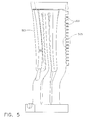
FIG. 3 shows a known airfoil configuration havingtrailing edge openings 211 having a known arrangement alongtrailing edge 107. Thetrailing edge openings 211 have a substantially oval geometry (i.e., a geometry having a substantially uniform width across a length) that allows the passage of an excessive quantity ofcooling fluid 204 and undesirably requires acooling fluid 204 restriction, such as a root plate, on thecooling fluid 204 feed to provide efficient operation of theblade 100. Another view of a prior art arrangement is shown inFIG. 7 , which illustrates a cross-section of atrailing edge opening 211, wherein the cross-sectional geometry has a substantially oval geometry. Thetrailing edge opening 211 known in the art was previously required to have awidth 701 that is substantially uniform across thelength 703 to provide sufficientceramic core 501 strength during casting. However, the cooling slots currently formed provide excessive flow of cooling fluid at reduced cavity pressure during operation, requiring the use of aroot plate 901 on the blade feed to limit the flow of cooling fluid.FIG. 9 shows a knownturbine blade 100 arrangement having aroot plate 901 disposed oninlet openings 205. The root plate undesirably increases manufacturing costs and provides additional maintenance costs by requiring the installation of an additional component adjacent the turbine component. - Accordingly, there is a need for an airfoil component in which cooling fluid flow through the trail edge slots is decreased, while the core during fabrication is sufficiently robust to withstand casting of the turbine component.
- A first aspect of the present invention includes an airfoil component having a body having a leading edge and a trailing edge. The component includes an internal cooling passageway and an elongated opening in communication with the internal cooling passageway. The opening is configured with a geometry that provides structural stability during casting and has a cross-section that sufficiently restricts airflow through the opening to provide efficient component operation.
- Another aspect of the present invention includes a gas turbine engine component casting insert having a ceramic insert body. The insert further includes core insert projections extending from the body having outer edge projections connected by a web portion. The outer edge projections have a thickness along the web portion that is greater than the thickness of the web portion. The core insert projections and web portion have sufficient structural stability to permit casting around the insert.
- Still another aspect of the present invention includes a method for casting a gas turbine engine component. The method includes providing a core insert having core insert projections with outer edge projections connected by a web portion. The outer edge projections have a thickness along the web portion that is greater than the thickness of the web portion. A gas turbine engine component is cast over the core insert. The core insert is then removed to provide a gas turbine engine having cooling passages and elongated openings in communication with the cooling passages. The opening formed from removal of the core insert have a geometry that sufficiently restricts airflow through the opening to provide efficient component operation.
- An advantage of an embodiment of the present invention is that the amount of bleed air from the compressor may be reduced and gas turbine engine operation may be more efficient.
- Another advantage of an embodiment of the present invention is that the reduced cooling flow of cooling fluid from the trailing edge reduces or eliminates the need for other fluid flow restrictions, such as root plates.
- Various features and advantages of the present invention will be apparent from the following more detailed description of the preferred embodiment, taken in conjunction with the accompanying drawings which illustrate, by way of example, the principles of the invention, and in which:
-
FIG. 1 illustrates an elevational perspective view of a turbine blade according to an embodiment of the present invention. -
FIG. 2 illustrates a partial cutaway view of a turbine blade according to an embodiment of the present invention. -
FIG. 3 illustrates a perspective view of an airfoil having trailing edge openings known in the art. -
FIG. 4 illustrates a perspective view of an airfoil having trailing edge openings according to an embodiment of the present invention. -
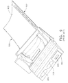
FIG. 5 illustrates a perspective view of a core insert according to an embodiment of the present invention. -
FIG. 6 illustrates an enlarged perspective view of a core insert according to an embodiment of the present invention. -
FIG. 7 illustrates a cross-sectional geometry of a trailing edge opening known in the art. -
FIG. 8 illustrates a cross-sectional geometry of a trailing edge opening according to an embodiment of the present invention. -
FIG. 9 illustrates a bottom perspective view a turbine blade having a root plate according to an embodiment of the present invention. - Wherever possible, the same reference numbers are used throughout the drawings to refer to the same or like parts.
- Illustrated in
FIG. 1 is anexemplary turbine blade 100 for a gas turbine engine designed to be operated in a hot gas stream that flows in an axial flow downstream direction. During operation of theblade 100,combustion gases 101 are generated by a combustor (not shown) and flow downstream over theairfoil 103. Theblade 100 includes ahollow airfoil 103 and a conventional root 104 used to secure theblade 100 to a rotor disk (not shown) of the gas turbine engine. Theairfoil 103 includes an upstreamleading edge 105,tip 106 and adownstream trailing edge 107 which is spaced chordally apart from theleading edge 105. Theairfoil 103 extends longitudinally in a radial direction away from the root 104. - As shown in
FIG. 2 , theairfoil 101 includes an internal serpentine cooling circuit havingcooling passages 201 traversing the hollow portions ofairfoil 103. The configuration of coolingpassageways 201 is not particularly limited and may include a plurality ofcircuits 203 that receives a coolingfluid 204, such as compressed air bled from the compressor of the gas turbine engine (not shown), throughinlet openings 205. Preferably,serpentine cooling circuit 203 are constructed so as to cause aserpentine cooling fluid 204 within thecooling circuit 203 to flow through thepassages 201 and exit through leadingedge openings 207,tip openings 209, trailingedge openings 211. The flow of cooling fluid 204 thereby cools theairfoil 103 from the heat of thecombustion gases 101 flowing over the outer surfaces thereof. In addition,airfoil 103 may include openings along the outer walls, the leading edge and/or the tip surfaces, as desired, to provide film cooling to various surfaces of theairfoil 103. As shown inFIG. 2 , thesefilm cooling openings edge 105 andtip 106, respectively. The present invention is not limited to the arrangement ofpassages 201 oropenings passages 201 that provides cooling to theairfoil 103. - The trailing
edge openings 211 receive a flow of cooling fluid 204 wherein the cooling fluid 204 flows through the trailingedge openings 211 and is discharged from theairfoil 103. Cooling air discharge apertures or trailingedge openings 211 are preferably designed to provide impingement cooling of the trailingedge 107. The present invention utilizes a configuration of trailingedge openings 211 that provides efficient cooling, without the need for a root plate or other cooling fluid 204 restriction, allowing for efficient gas turbine engine operation. - Although an exemplary
gas turbine blade 100 is illustrated inFIGs. 1 and2 , the invention applies equally as well to substantially fixed turbine stator vanes having similar airfoils and turbine shrouds, which may be similarly cooled in accordance with the present invention. Further, theairfoil 103 may have any other conventional features for enhancing the cooling thereof, such as turbulators or pins (not shown), which are well known in the art. In addition, thermal barrier coatings (TBCs), which are well known in the technology, may also be used to improve thermal characteristics of theairfoil 103. -
FIG. 4 shows anairfoil 103 having trailingedge openings 211 having an arrangement of trailingedge openings 211 along trailingedge 107 according to an embodiment of the present invention. In this embodiment, the trailingedge openings 211 having a pinched geometry that allow a flow rate of cooling fluid 204 that is less than the flow of cooling fluid 204 through the trailingedge openings 211 ofFIG. 3 . The reducedcooling fluid 204 flow provides efficient cooling, without the need for a root plate or other cooling fluid 204 restriction, allowing for efficient gas turbine engine operation. -
FIG. 5 shows a core assembly for casting turbine blades with serpentine cooling circuits, the internalceramic core 501 is formed as a serpentine element having a number of long, thin branches. The internalceramic core 501 is formed as a serpentine element having a number of long, thin branches. Theceramic core 501 has mechnical properties, such as strength, sufficient to withstand the pouring of casting material (e.g., superalloy metal) while maintaining the tight positioning requirement for theceramic core 501 during casting. The casting of theturbine blade 100 may be performed usingconventional turbine blade 100 casting methods. For example, theturbine blade 100 may be investment cast from a directionally solidified or single crystal superalloy aroundceramic core 501. Upon completion of the casting and removal of the outer ceramic material, theceramic core 501 may be chemically removed to provide thehollow turbine blade 100. - An embodiment of the present invention utilizes a
ceramic core 501 that is formed utilizing cores insertprojections 503 having a geometry corresponding to the pinched geometry trailingedge openings 211. The pinchedtrail edge openings 211 are cast utilizingceramic core 501insert projections 503 that provide a slot geometry having a pinched geometry to provide strength to theceramic core 501 and provide sufficient cooling along the trailing edge opening 211 of the turbine component. -
FIG. 6 shows an enlarged view ofportion 505 ofFIG. 5 illustratingceramic core 501insert projections 503. As better shown in the enlarged view ofportion 505 inFIG. 6 , theceramic core 501insert projection 503 geometry includesouter edge projections 601 providing one or more ribs or splines connected by aweb portion 603, which extends betweenouter edge projections 601. While not limited to the geometry shown inFIGs. 5 and6 , theinsert projections 503 preferably include a minimum and a maximum thickness across the length of theweb portion 603. For example, theweb portion 603 may have a thickness (i.e., a thickness measured along an axis into the paper, as shown inFIGs 5 and6 ) along theweb portion 603 that is less than about 90% of the thickness of theouter edge projections 601, preferably the thickness of theweb portion 603 is less than about 85% of the thickness of theouter edge projections 601 and more preferably thethickness web portion 603 is less than about 80% of the thickness of theouter edge projections 601. The combination of theouter edge projections 601 and theweb portion 603 provides sufficient mechanical properties to permit casting of theturbine blade 100 and to maintain positioning during casting. Theceramic core 501 insert corresponds to geometry in the finishedturbine blade 100 having trailingedge openings 211, when theceramic core 501 insert is removed, that reduces or eliminates excessive flow of cooling fluid 204 at reduced cavity pressure during operation. The flow of coolingfluid 204 is sufficiently limited by the trailingedge openings 211 to reduce or eliminate the need for a root plate on the blade feed to limit the flow of coolingfluid 204. -
FIG. 8 illustrates an embodiment of the invention having a pinched geometry. By pinched geometry it is meant that the cross-sectional geometry of the trailing edge opening 211 includes an elongated opening having afirst dimension 801 arranged in the elongated direction and a secondminimum dimension 803 and secondmaximum dimension 804 that are substantially perpendicular to the first dimension. Thefirst dimension 801 includes afirst end 805 and asecond end 807 wherein the secondminimum dimension 803 includes a minimum value at a location between thefirst end 805 and thesecond end 807. In a preferred embodiment, the trailing edge opening 211 has a pinched geometry wherein thefirst end 805 andsecond end 807 each include substantially circular cross-sectional geometries extending for a secondmaximum dimension 804 connected by a reducedthickness chord 809 extending along aside edge 811 of trailingedge opening 211. For example, the secondmaximum dimension 804 may have a maximum near thefirst end 805 andsecond end 807 of about 0.013 inches and the secondminimum dimension 803 may be 0.010 inches alongchord 809. The secondminimum dimension 803 may be less than or equal to about 90% of the secondmaximum dimension 804, preferably less than or equal to about 85% of the secondmaximum dimension 804 and still more preferably 80% of the secondmaximum dimension 804. - In another embodiment of the invention, the trailing edge opening 211 may include a plurality of second
minimum dimensions 803 betweenfirst end 805 andsecond end 807, for example, wherein the secondmaximum dimension 804 is located at a location near the center of first dimension 801 a substantially T-shapedopening 211. Likewise, the secondmaximum dimension 804 may extend in two directions past secondminimum dimension 803. The present invention is not limited to the above configurations of thefirst dimension 801, the secondminimum dimension 803 and secondmaximum dimension 804 and may include a plurality of each or both of the secondminimum dimension 803 and secondmaximum dimension 804. The present invention utilizes the cross-sectional geometry formed to provide a reduced amount of cooling fluid 204 flow, while providing a sufficiently strongceramic core 501 insert that allows casting of theblade 100. The coolingfluid 204 is therefore used more efficiently andless cooling fluid 204 is bled from the compressor for increasing the overall efficiency of operation of the gas turbine engine. - While the invention has been described with reference to a preferred embodiment, it will be understood by those skilled in the art that various changes may be made and equivalents may be substituted for elements thereof without departing from the scope of the invention. In addition, many modifications may be made to adapt a particular situation or material to the teachings of the invention without departing from the essential scope thereof: Therefore, it is intended that the invention not be limited to the particular embodiment disclosed as the best mode contemplated for carrying out this invention, but that the invention will include all embodiments falling within the scope of the appended claims.
Claims (10)
- An airfoil component (100) comprising:a body having a leading edge (105) and a trailing edge (107);an internal cooling passageway (201);an elongated opening (211), the opening (211) being in communication with the internal cooling passageway (201); andwherein the opening (211) is configured with a geometry that provides structural stability during casting and has a cross-section that sufficiently restricts cooling fluid flow through the opening (211) to provide efficient component operation.
- The component (100) of claim 1, wherein the opening (211) has an elongated geometry having first dimension (801) and a second dimension (803,804), the first dimension (801) having a first end (805) and a second end 807 disposed at opposite ends of the opening (211); and
the second dimension (803,804) being arranged perpendicular to the first dimension (801) and further including at least one minimum value (803) and at least one maximum value (804) disposed between the first (805) and second end (807). - The component (100) of claim 2, wherein the at least one minimum value (803) is less than about 90% of the maximum value (804).
- The component (100) of claim 3, wherein the at least one minimum value (803) is less than about 80% of the maximum value (804).
- The component (100) of any preceding claim, wherein the openings are disposed adjacent the trailing edge (107).
- The component (100) of any preceding claim, wherein the component (100) is a turbine blade or vane.
- The component (100) of any preceding claim, wherein the component (100) is a turbine shroud.
- The component (100) of any preceding claim, wherein the opening is formed by casting the component (100) about a casting insert comprising:a ceramic insert body (501);core insert projections (503) extending from the body having outer edge projections (601) connected by a web portion (603), the outer edge projections (601) having a thickness along the web portion (603) that is greater than the thickness of the web portion (603); andwherein the core insert projections (503) and web portion (603) have sufficient structural stability to permit casting the component (100) around the insert.
- The component (100) of claim 8, wherein the web portion (603) has a thickness along the web portion (603) that is less than about 90% of the thickness of the outer edge projections (601).
- The component (100) of claim 9, wherein the web portion (603) has a thickness along the web portion (603) that is less than about 80% of the thickness of the outer edge projections (601).
Applications Claiming Priority (1)
| Application Number | Priority Date | Filing Date | Title |
|---|---|---|---|
| US11/616,176 US20100034662A1 (en) | 2006-12-26 | 2006-12-26 | Cooled airfoil and method for making an airfoil having reduced trail edge slot flow |
Publications (3)
| Publication Number | Publication Date |
|---|---|
| EP1942251A2 true EP1942251A2 (en) | 2008-07-09 |
| EP1942251A3 EP1942251A3 (en) | 2010-09-08 |
| EP1942251B1 EP1942251B1 (en) | 2012-04-11 |
Family
ID=38984139
Family Applications (1)
| Application Number | Title | Priority Date | Filing Date |
|---|---|---|---|
| EP07123432A Expired - Fee Related EP1942251B1 (en) | 2006-12-26 | 2007-12-18 | Cooled airfoil having reduced trailing edge slot flow and corresponding casting method |
Country Status (5)
| Country | Link |
|---|---|
| US (1) | US20100034662A1 (en) |
| EP (1) | EP1942251B1 (en) |
| JP (1) | JP2008163942A (en) |
| CA (1) | CA2614031A1 (en) |
| RU (1) | RU2007148893A (en) |
Cited By (8)
| Publication number | Priority date | Publication date | Assignee | Title |
|---|---|---|---|---|
| ITMI20090977A1 (en) * | 2009-06-04 | 2010-12-05 | Ansaldo Energia Spa | TURBINE SHOVEL |
| EP2343435A1 (en) * | 2009-11-25 | 2011-07-13 | Honeywell International Inc. | Gas turbine engine components with improved film cooling |
| US8371814B2 (en) | 2009-06-24 | 2013-02-12 | Honeywell International Inc. | Turbine engine components |
| US8628293B2 (en) | 2010-06-17 | 2014-01-14 | Honeywell International Inc. | Gas turbine engine components with cooling hole trenches |
| WO2016034802A1 (en) * | 2014-09-04 | 2016-03-10 | Snecma | Method for producing a ceramic core |
| US9650900B2 (en) | 2012-05-07 | 2017-05-16 | Honeywell International Inc. | Gas turbine engine components with film cooling holes having cylindrical to multi-lobe configurations |
| US10113433B2 (en) | 2012-10-04 | 2018-10-30 | Honeywell International Inc. | Gas turbine engine components with lateral and forward sweep film cooling holes |
| US11021965B2 (en) | 2016-05-19 | 2021-06-01 | Honeywell International Inc. | Engine components with cooling holes having tailored metering and diffuser portions |
Families Citing this family (8)
| Publication number | Priority date | Publication date | Assignee | Title |
|---|---|---|---|---|
| US8974182B2 (en) * | 2012-03-01 | 2015-03-10 | General Electric Company | Turbine bucket with a core cavity having a contoured turn |
| US10107107B2 (en) * | 2012-06-28 | 2018-10-23 | United Technologies Corporation | Gas turbine engine component with discharge slot having oval geometry |
| EP2959130B1 (en) * | 2013-02-19 | 2019-10-09 | United Technologies Corporation | Gas turbine engine blade, core for manufacturing said blade, and method for manufacturing said core |
| FR3034128B1 (en) * | 2015-03-23 | 2017-04-14 | Snecma | CERAMIC CORE FOR MULTI-CAVITY TURBINE BLADE |
| EP3415250A1 (en) * | 2017-06-15 | 2018-12-19 | Siemens Aktiengesellschaft | Casting core with crossover bridge |
| DE102019125779B4 (en) * | 2019-09-25 | 2024-03-21 | Man Energy Solutions Se | Blade of a turbomachine |
| DE102020207646A1 (en) * | 2020-06-22 | 2021-12-23 | Siemens Aktiengesellschaft | Turbine blade and method for processing such |
| CN113623014B (en) * | 2021-07-22 | 2023-04-14 | 西安交通大学 | Gas turbine blade-wheel disc combined cooling structure |
Citations (4)
| Publication number | Priority date | Publication date | Assignee | Title |
|---|---|---|---|---|
| US4529358A (en) * | 1984-02-15 | 1985-07-16 | The United States Of America As Represented By The Administrator Of The National Aeronautics And Space Administration | Vortex generating flow passage design for increased film cooling effectiveness |
| US4992025A (en) * | 1988-10-12 | 1991-02-12 | Rolls-Royce Plc | Film cooled components |
| US6092982A (en) * | 1996-05-28 | 2000-07-25 | Kabushiki Kaisha Toshiba | Cooling system for a main body used in a gas stream |
| EP1609949A1 (en) * | 2004-06-23 | 2005-12-28 | General Electric Company | Film cooled wall with chevron-shaped cooling holes |
Family Cites Families (27)
| Publication number | Priority date | Publication date | Assignee | Title |
|---|---|---|---|---|
| US3706508A (en) * | 1971-04-16 | 1972-12-19 | Sean Lingwood | Transpiration cooled turbine blade with metered coolant flow |
| US4236870A (en) * | 1977-12-27 | 1980-12-02 | United Technologies Corporation | Turbine blade |
| US4626169A (en) * | 1983-12-13 | 1986-12-02 | United Technologies Corporation | Seal means for a blade attachment slot of a rotor assembly |
| US4582467A (en) * | 1983-12-22 | 1986-04-15 | United Technologies Corporation | Two stage rotor assembly with improved coolant flow |
| US4601638A (en) * | 1984-12-21 | 1986-07-22 | United Technologies Corporation | Airfoil trailing edge cooling arrangement |
| US4820123A (en) * | 1988-04-25 | 1989-04-11 | United Technologies Corporation | Dirt removal means for air cooled blades |
| GB8830152D0 (en) * | 1988-12-23 | 1989-09-20 | Rolls Royce Plc | Cooled turbomachinery components |
| US5651662A (en) * | 1992-10-29 | 1997-07-29 | General Electric Company | Film cooled wall |
| JP2810023B2 (en) * | 1996-09-18 | 1998-10-15 | 株式会社東芝 | High temperature member cooling device |
| US5820774A (en) * | 1996-10-28 | 1998-10-13 | United Technologies Corporation | Ceramic core for casting a turbine blade |
| JPH1162507A (en) * | 1997-08-11 | 1999-03-05 | Ishikawajima Harima Heavy Ind Co Ltd | Film cooling hole |
| US6059529A (en) * | 1998-03-16 | 2000-05-09 | Siemens Westinghouse Power Corporation | Turbine blade assembly with cooling air handling device |
| DE19821770C1 (en) * | 1998-05-14 | 1999-04-15 | Siemens Ag | Mold for producing a hollow metal component |
| US6126396A (en) * | 1998-12-09 | 2000-10-03 | General Electric Company | AFT flowing serpentine airfoil cooling circuit with side wall impingement cooling chambers |
| JP4092674B2 (en) * | 1999-03-02 | 2008-05-28 | 日立金属株式会社 | Molding method of wax model with ceramic core |
| US6176677B1 (en) * | 1999-05-19 | 2001-01-23 | Pratt & Whitney Canada Corp. | Device for controlling air flow in a turbine blade |
| JP2001012204A (en) * | 1999-06-30 | 2001-01-16 | Toshiba Corp | Gas turbine blade |
| US6186741B1 (en) * | 1999-07-22 | 2001-02-13 | General Electric Company | Airfoil component having internal cooling and method of cooling |
| US6390774B1 (en) * | 2000-02-02 | 2002-05-21 | General Electric Company | Gas turbine bucket cooling circuit and related process |
| US6325593B1 (en) * | 2000-02-18 | 2001-12-04 | General Electric Company | Ceramic turbine airfoils with cooled trailing edge blocks |
| US6491496B2 (en) * | 2001-02-23 | 2002-12-10 | General Electric Company | Turbine airfoil with metering plates for refresher holes |
| US6416275B1 (en) * | 2001-05-30 | 2002-07-09 | Gary Michael Itzel | Recessed impingement insert metering plate for gas turbine nozzles |
| US6551062B2 (en) * | 2001-08-30 | 2003-04-22 | General Electric Company | Turbine airfoil for gas turbine engine |
| US6612811B2 (en) * | 2001-12-12 | 2003-09-02 | General Electric Company | Airfoil for a turbine nozzle of a gas turbine engine and method of making same |
| US6933459B2 (en) * | 2003-02-03 | 2005-08-23 | General Electric Company | Methods and apparatus for fabricating a turbine engine blade |
| US6974306B2 (en) * | 2003-07-28 | 2005-12-13 | Pratt & Whitney Canada Corp. | Blade inlet cooling flow deflector apparatus and method |
| US7510376B2 (en) * | 2005-08-25 | 2009-03-31 | General Electric Company | Skewed tip hole turbine blade |
-
2006
- 2006-12-26 US US11/616,176 patent/US20100034662A1/en not_active Abandoned
-
2007
- 2007-12-13 CA CA002614031A patent/CA2614031A1/en not_active Abandoned
- 2007-12-18 EP EP07123432A patent/EP1942251B1/en not_active Expired - Fee Related
- 2007-12-25 RU RU2007148893/06A patent/RU2007148893A/en unknown
- 2007-12-26 JP JP2007333394A patent/JP2008163942A/en active Pending
Patent Citations (4)
| Publication number | Priority date | Publication date | Assignee | Title |
|---|---|---|---|---|
| US4529358A (en) * | 1984-02-15 | 1985-07-16 | The United States Of America As Represented By The Administrator Of The National Aeronautics And Space Administration | Vortex generating flow passage design for increased film cooling effectiveness |
| US4992025A (en) * | 1988-10-12 | 1991-02-12 | Rolls-Royce Plc | Film cooled components |
| US6092982A (en) * | 1996-05-28 | 2000-07-25 | Kabushiki Kaisha Toshiba | Cooling system for a main body used in a gas stream |
| EP1609949A1 (en) * | 2004-06-23 | 2005-12-28 | General Electric Company | Film cooled wall with chevron-shaped cooling holes |
Cited By (17)
| Publication number | Priority date | Publication date | Assignee | Title |
|---|---|---|---|---|
| WO2010139766A1 (en) * | 2009-06-04 | 2010-12-09 | Ansaldo Energia S.P.A. | Turbine blade |
| RU2528781C2 (en) * | 2009-06-04 | 2014-09-20 | Ансальдо Энергия С.П.А. | Turbine blade |
| ITMI20090977A1 (en) * | 2009-06-04 | 2010-12-05 | Ansaldo Energia Spa | TURBINE SHOVEL |
| US8371814B2 (en) | 2009-06-24 | 2013-02-12 | Honeywell International Inc. | Turbine engine components |
| EP2343435A1 (en) * | 2009-11-25 | 2011-07-13 | Honeywell International Inc. | Gas turbine engine components with improved film cooling |
| US8529193B2 (en) | 2009-11-25 | 2013-09-10 | Honeywell International Inc. | Gas turbine engine components with improved film cooling |
| US8628293B2 (en) | 2010-06-17 | 2014-01-14 | Honeywell International Inc. | Gas turbine engine components with cooling hole trenches |
| US9650900B2 (en) | 2012-05-07 | 2017-05-16 | Honeywell International Inc. | Gas turbine engine components with film cooling holes having cylindrical to multi-lobe configurations |
| US10113433B2 (en) | 2012-10-04 | 2018-10-30 | Honeywell International Inc. | Gas turbine engine components with lateral and forward sweep film cooling holes |
| FR3025444A1 (en) * | 2014-09-04 | 2016-03-11 | Snecma | PROCESS FOR PRODUCING A CERAMIC CORE |
| CN106687232A (en) * | 2014-09-04 | 2017-05-17 | 赛峰航空器发动机 | Method for producing a ceramic core |
| WO2016034802A1 (en) * | 2014-09-04 | 2016-03-10 | Snecma | Method for producing a ceramic core |
| CN106687232B (en) * | 2014-09-04 | 2019-04-05 | 赛峰航空器发动机 | Method for manufacturing ceramic core |
| US10328485B2 (en) | 2014-09-04 | 2019-06-25 | Safran Aircraft Engines | Method for producing a ceramic core |
| RU2699346C2 (en) * | 2014-09-04 | 2019-09-04 | Сафран Эркрафт Энджинз | Ceramic rod manufacturing method |
| US11021965B2 (en) | 2016-05-19 | 2021-06-01 | Honeywell International Inc. | Engine components with cooling holes having tailored metering and diffuser portions |
| US11286791B2 (en) | 2016-05-19 | 2022-03-29 | Honeywell International Inc. | Engine components with cooling holes having tailored metering and diffuser portions |
Also Published As
| Publication number | Publication date |
|---|---|
| US20100034662A1 (en) | 2010-02-11 |
| EP1942251B1 (en) | 2012-04-11 |
| EP1942251A3 (en) | 2010-09-08 |
| CA2614031A1 (en) | 2008-06-26 |
| JP2008163942A (en) | 2008-07-17 |
| RU2007148893A (en) | 2009-06-27 |
Similar Documents
| Publication | Publication Date | Title |
|---|---|---|
| EP1942251B1 (en) | Cooled airfoil having reduced trailing edge slot flow and corresponding casting method | |
| EP1070829B1 (en) | Internally cooled airfoil | |
| US7377746B2 (en) | Airfoil cooling circuits and method | |
| EP2071126B1 (en) | Turbine blades and methods of manufacturing | |
| EP1895098B1 (en) | Improved High Effectiveness Cooled Turbine Blade | |
| JP4453826B2 (en) | 3-circuit turbine blade | |
| EP2855857B1 (en) | Blade outer air seal with cored passages | |
| EP1055800B1 (en) | Turbine airfoil with internal cooling | |
| US8734108B1 (en) | Turbine blade with impingement cooling cavities and platform cooling channels connected in series | |
| US8348614B2 (en) | Coolable airfoil trailing edge passage | |
| US6132169A (en) | Turbine airfoil and methods for airfoil cooling | |
| US6896487B2 (en) | Microcircuit airfoil mainbody | |
| JP4311919B2 (en) | Turbine airfoils for gas turbine engines | |
| EP2141326A2 (en) | Airfoil with tapered radial cooling passage | |
| KR20060057508A (en) | Airfoil with supplemental cooling channel adjacent leading edge | |
| CA2462986A1 (en) | Method and apparatus for cooling an airfoil | |
| JP2001073705A (en) | Turbine rotor blade provided with rear-edge pressure wall given priority in cooling | |
| US7387492B2 (en) | Methods and apparatus for cooling turbine blade trailing edges | |
| US11230929B2 (en) | Turbine component with dust tolerant cooling system | |
| EP3594448B1 (en) | Airfoil with leading edge convective cooling system | |
| US11333042B2 (en) | Turbine blade with dust tolerant cooling system | |
| EP3645838B1 (en) | Turbine airfoil with trailing edge features and casting core | |
| CN113677872B (en) | Metal cast component for manufacturing turbine engine fan blade and wax loss method | |
| WO2017039568A1 (en) | Turbine airfoil cooling channel with fenced pedestals |
Legal Events
| Date | Code | Title | Description |
|---|---|---|---|
| PUAI | Public reference made under article 153(3) epc to a published international application that has entered the european phase |
Free format text: ORIGINAL CODE: 0009012 |
|
| AK | Designated contracting states |
Kind code of ref document: A2 Designated state(s): AT BE BG CH CY CZ DE DK EE ES FI FR GB GR HU IE IS IT LI LT LU LV MC MT NL PL PT RO SE SI SK TR |
|
| AX | Request for extension of the european patent |
Extension state: AL BA HR MK RS |
|
| PUAL | Search report despatched |
Free format text: ORIGINAL CODE: 0009013 |
|
| AK | Designated contracting states |
Kind code of ref document: A3 Designated state(s): AT BE BG CH CY CZ DE DK EE ES FI FR GB GR HU IE IS IT LI LT LU LV MC MT NL PL PT RO SE SI SK TR |
|
| AX | Request for extension of the european patent |
Extension state: AL BA HR MK RS |
|
| RIC1 | Information provided on ipc code assigned before grant |
Ipc: B22C 9/24 20060101ALI20100730BHEP Ipc: B22C 9/04 20060101ALI20100730BHEP Ipc: F01D 5/08 20060101ALI20100730BHEP Ipc: F01D 5/18 20060101AFI20080207BHEP |
|
| 17P | Request for examination filed |
Effective date: 20110308 |
|
| AKX | Designation fees paid |
Designated state(s): DE FR GB |
|
| RTI1 | Title (correction) |
Free format text: COOLED AIRFOIL HAVING REDUCED TRAILING EDGE SLOT FLOW AND CORRESPONDING CASTING METHOD |
|
| GRAP | Despatch of communication of intention to grant a patent |
Free format text: ORIGINAL CODE: EPIDOSNIGR1 |
|
| GRAS | Grant fee paid |
Free format text: ORIGINAL CODE: EPIDOSNIGR3 |
|
| GRAA | (expected) grant |
Free format text: ORIGINAL CODE: 0009210 |
|
| AK | Designated contracting states |
Kind code of ref document: B1 Designated state(s): DE FR GB |
|
| REG | Reference to a national code |
Ref country code: GB Ref legal event code: FG4D |
|
| REG | Reference to a national code |
Ref country code: DE Ref legal event code: R096 Ref document number: 602007021855 Country of ref document: DE Effective date: 20120606 |
|
| PLBE | No opposition filed within time limit |
Free format text: ORIGINAL CODE: 0009261 |
|
| STAA | Information on the status of an ep patent application or granted ep patent |
Free format text: STATUS: NO OPPOSITION FILED WITHIN TIME LIMIT |
|
| PGFP | Annual fee paid to national office [announced via postgrant information from national office to epo] |
Ref country code: GB Payment date: 20121227 Year of fee payment: 6 |
|
| 26N | No opposition filed |
Effective date: 20130114 |
|
| PGFP | Annual fee paid to national office [announced via postgrant information from national office to epo] |
Ref country code: FR Payment date: 20130110 Year of fee payment: 6 |
|
| PGFP | Annual fee paid to national office [announced via postgrant information from national office to epo] |
Ref country code: DE Payment date: 20121231 Year of fee payment: 6 |
|
| REG | Reference to a national code |
Ref country code: DE Ref legal event code: R097 Ref document number: 602007021855 Country of ref document: DE Effective date: 20130114 |
|
| REG | Reference to a national code |
Ref country code: DE Ref legal event code: R119 Ref document number: 602007021855 Country of ref document: DE |
|
| GBPC | Gb: european patent ceased through non-payment of renewal fee |
Effective date: 20131218 |
|
| REG | Reference to a national code |
Ref country code: DE Ref legal event code: R119 Ref document number: 602007021855 Country of ref document: DE Effective date: 20140701 |
|
| REG | Reference to a national code |
Ref country code: FR Ref legal event code: ST Effective date: 20140829 |
|
| PG25 | Lapsed in a contracting state [announced via postgrant information from national office to epo] |
Ref country code: DE Free format text: LAPSE BECAUSE OF NON-PAYMENT OF DUE FEES Effective date: 20140701 |
|
| PG25 | Lapsed in a contracting state [announced via postgrant information from national office to epo] |
Ref country code: GB Free format text: LAPSE BECAUSE OF NON-PAYMENT OF DUE FEES Effective date: 20131218 Ref country code: FR Free format text: LAPSE BECAUSE OF NON-PAYMENT OF DUE FEES Effective date: 20131231 |