EP1942216A1 - Weft knitting machine having movable yarn guide - Google Patents
Weft knitting machine having movable yarn guide Download PDFInfo
- Publication number
- EP1942216A1 EP1942216A1 EP06810662A EP06810662A EP1942216A1 EP 1942216 A1 EP1942216 A1 EP 1942216A1 EP 06810662 A EP06810662 A EP 06810662A EP 06810662 A EP06810662 A EP 06810662A EP 1942216 A1 EP1942216 A1 EP 1942216A1
- Authority
- EP
- European Patent Office
- Prior art keywords
- needle
- sinker
- needle bed
- knitting
- yarn guide
- Prior art date
- Legal status (The legal status is an assumption and is not a legal conclusion. Google has not performed a legal analysis and makes no representation as to the accuracy of the status listed.)
- Granted
Links
- 238000009940 knitting Methods 0.000 title claims abstract description 194
- 150000001875 compounds Chemical class 0.000 claims description 5
- 239000004744 fabric Substances 0.000 abstract description 16
- 210000002105 tongue Anatomy 0.000 description 16
- 230000007246 mechanism Effects 0.000 description 6
- 239000000463 material Substances 0.000 description 2
- 238000007747 plating Methods 0.000 description 1
Images


Classifications
-
- D—TEXTILES; PAPER
- D04—BRAIDING; LACE-MAKING; KNITTING; TRIMMINGS; NON-WOVEN FABRICS
- D04B—KNITTING
- D04B15/00—Details of, or auxiliary devices incorporated in, weft knitting machines, restricted to machines of this kind
- D04B15/06—Sinkers
-
- D—TEXTILES; PAPER
- D04—BRAIDING; LACE-MAKING; KNITTING; TRIMMINGS; NON-WOVEN FABRICS
- D04B—KNITTING
- D04B15/00—Details of, or auxiliary devices incorporated in, weft knitting machines, restricted to machines of this kind
- D04B15/10—Needle beds
-
- D—TEXTILES; PAPER
- D04—BRAIDING; LACE-MAKING; KNITTING; TRIMMINGS; NON-WOVEN FABRICS
- D04B—KNITTING
- D04B15/00—Details of, or auxiliary devices incorporated in, weft knitting machines, restricted to machines of this kind
- D04B15/66—Devices for determining or controlling patterns ; Programme-control arrangements
- D04B15/68—Devices for determining or controlling patterns ; Programme-control arrangements characterised by the knitting instruments used
- D04B15/70—Devices for determining or controlling patterns ; Programme-control arrangements characterised by the knitting instruments used in flat-bed knitting machines
Definitions
- the present invention relates to a weft knitting machine provided with a movable yarn guide that moves forward and backward together with a knitting needle with respect to a needle bed gap and that guides a knitting yarn to a hook of the knitting needle.
- a knitting yarn is fed from above the needle bed gap to the hooks of the knitting needles, and thus a fabric is knitted.
- a knitting yarn is fed from a yarn feeding port of a yarn feeding member such as a yarn feeder in the vicinity of the center portion of the needle bed gap, in a state where a hook of a knitting needle has been moved forward to a far position in the needle bed gap.
- the hook of the knitting needle that has been moved forward to the needle bed gap catches a knitting yarn when the knitting needle is moved backward from the needle bed gap and pulled into the needle bed.
- the knitting needles form knitted loops by pulling a knitting yarn into the needle bed along needle grooves that are provided on the needle bed.
- the knitting loops are composed of needle loops that are formed by the hooks of the knitting needles pulling the knitting yarn into the needle bed and sinker loops that are formed by sinkers positioned between the adjacent knitting needles and facing the needle bed gap.
- the size of formed knitted loops is determined by stitch density to which is related pulling the hooks of the knitting needles into the needle bed. At the time of stitch determination, the position of the sinkers facing the needle bed gap serves as a reference.
- a movable yarn guide member whose front end can move forward to the vicinity of the center of the needle bed gap over the front end of the sinker is used in order to reliably guide a knitting yarn to the hook.
- the movable yarn guide member moves backward from the needle bed gap to avoid interference with the yarn feeding port.
- the movable yarn guide member moves forward to the needle bed gap and guides the knitting yarn to the hook.
- a sinker is also a movable sinker that is swingingly displaced about a supporting point provided closer to the front end of the needle bed, and the front end portion that is swingingly displaced also has an action of pressing the fabric downward in the needle bed gap.
- a compound needle is used in which a needle main body and a slider are separated, and a hook provided at the front end of the needle main body is opened and closed with the slider.
- the needle main body and the slider are independently driven, and the slider remains in the vicinity of the front end of the needle bed during a period in which the hook of the needle main body has moved forward to the needle bed gap.
- the slider when the needle main body has moved forward to the needle bed gap, it is necessary for the slider to move forward to the vicinity of the needle bed gap such that the knocked-over previous loop can easily escape to the needle bed gap.
- the knitting yarn may be not hooked on the hook.
- the movable yarn guide such as the movable guide member also has an action of preventing a knitting yarn from being caught by the slider.
- the needle beds are opposed to each other so that the needle bed gap is interposed therebetween.
- the reason for this is to make it possible to knit a fabric in so-called rib knitting or rib stitch using knitting needles of both needle beds, by knitting face stitches and back stitches of stitches with the knitting needles of the respective needle beds, and to knit various fabric patterns also using stitch transferring.
- tubular fabrics have been also knitted using both needle beds.
- JP-B2 7-96740 a weft knitting machine also has been developed in which two upper and lower needle beds are respectively provided on both sides that are opposed to each other so that a needle bed gap is interposed therebetween, that is, four needle beds in total are used, in order to knit a tubular fabric with various fabric patterns.
- JP-B2 7-96740 a common movable sinker for double-stage needle beds is used, and a movable yarn guide is not used.
- fancy yarns In a weft knitting machine, as a knitting yarn, it is also required to use various fancy yarns called, for example, fancy twisted yarns.
- the fancy twisted yarns include knot yarns in which knots are formed at intervals and loop yarns in which loops made of a wound yarn are continuously wound around a core yarn.
- Interlaced yarns are also used that are produced by interlacing yarns through an air-jet. These yarns occupy a larger space than ordinary twisted knitting yarns. Thus, when a part of these yarns is hooked on a hook and pulled into a needle bed, these yarns are easily caught by a slider or the like in the vicinity of a stitch determination position.
- knitting is performed simultaneously using a plurality of knitting yarns
- examples thereof include plating stitch that uses two knitting yarns and multiple yarn stitch that uses a larger number of thin knitting yarns.
- this sort of knitting yarn is used, as a sinker, a fixed sinker having a recess is used such that the position of a knitting yarn is stable at the time of stitch determination.
- the recess allows the slider to easily project or move closer to the needle bed gap, and thus a knitting yarn is more easily caught by the slider.
- the movable yarn guide member as described in JP-B2 3333304 is formed so as not to interfere with a path through which a knitting yarn is pulled, in order not to block the hook pulling the knitting yarn even when the movable yarn guide member moves forward to the needle bed gap.
- the movable yarn guide member hardly contributes to preventing a knitting yarn from being caught by the slider.
- a configuration is also conceivable in which the front end of the movable yarn guide member is extended so as to interfere with the path through which the knitting yarn is pulled, in order to separate the knitting yarn and the front end of the slider as much as possible not only when the slider projects from the recess of the fixed sinker to the needle bed gap but also when the slider does not project.
- the invention is directed to a weft knitting machine with a movable yarn guide in which a knitting needle is a compound needle comprising a needle main body and a slider, the needle main body is moved forward and backward with respect to a needle bed gap, a hook at a front end of the needle main body receives a knitting yarn fed from a yarn feeding port, a sinker for forming a sinker loop when forming a knitted loop by pulling the hook into a needle bed is provided on the needle bed gap side on the needle bed, and the movable yarn guide moves forward and backward together with the knitting needle with respect to the needle bed gap to guide a knitting yarn to the hook, the weft knitting machine comprising:
- a portion facing the needle bed gap and forming the sinker loop is in a shape of a plate
- the movable yarn guide moves forward and backward with respect to the needle bed gap while at least a part of the movable yarn guide slides along the sinker, and in the portion where the movable yarn guide and the sinker slide along each other, a concavity in which the sinker and the movable yarn guide are fitted to each other is formed such that its total thickness is the same as a thickness of the plate-like sinker.
- the drive means makes an amount of the forward movement of the movable yarn guide to the needle bed gap smaller than that in the vicinity of a position where the knitting yarn is received by the hook.
- the weft knitting machine is a four-bed weft knitting machine in which two pairs of upper and lower needle beds are provided so as to be opposed to each other in a state where the needle bed gap is interposed therebetween.
- Figs. 1A to 1D are side views showing the operation of a movable yarn guide 1, in a weft knitting machine 2 with a movable yarn guide 1 according to one embodiment of the invention.
- the weft knitting machine 2 is a four-bed weft knitting machine in which two pairs of upper and lower needle beds 3 and 4 are provided so as to be opposed to each other in a state where a needle bed gap 5 is interposed therebetween.
- the two pairs of needle beds 3 and 4 are symmetrically arranged on a front side and a back side with respect to a virtual center plane 5a in the needle bed gap 5 extending in a vertical direction.
- a side on which the front pair of the needle beds 3 and 4 is arranged is taken as a front side.
- Each of the needle beds 3 and 4 is shown in a simplified manner.
- a movable yarn guide 1 is provided on the upper needle bed 3.
- a fixed sinker 6 is supported on the lower needle bed 4.
- the sinker 6 is provided with a recess 6a used for precisely performing stitch determination for knitting yarns in multiple yarn stitch or the like.
- knitting needles 7 and 8 that are compound needles are respectively arranged so as to be movable forward and backward with respect to the needle bed gap 5.
- the knitting needles 7 and 8 respectively include needle main bodies 7a and 8a and sliders 7b and 8b.
- the front ends of the needle main bodies 7a and 8a are respectively provided with hooks 7c and 8c.
- the front ends of the sliders 7b and 8b are respectively provided with tongues 7d and 8d that open and close the hooks 7c and 8c.
- Each of the needle beds 3 and 4 is disposed such that a longitudinal direction thereof is perpendicular to the sheet of the drawing.
- a large number of needle grooves are formed in the longitudinal direction on the needle beds 3 and 4, and the knitting needles 7 and 8 are respectively accommodated in the needle grooves.
- Carriage travel back and forth in the longitudinal direction on the needle beds 3 and 4, and cam mechanisms mounted on the carriages drive the knitting needles 7 and 8 and the movable yarn guide 1 forward and backward with respect to the needle bed gap 5.
- the knitting needles 7 and 8 are simultaneously driven from the upper and lower needle beds 3 and 4, the upper and lower knitting needles 7 and 8 mechanically interfere with each other, and thus either one of the knitting needles 7 and 8 is selectively driven.
- a front edge of the upper and lower needle beds 3 and 4 facing the needle bed gap 5 is substantially formed by a wire material 9 such as a piano wire passing through in the longitudinal direction.
- Fig. 1A shows a state in which the knitting needle 8 has moved forward from the lower needle bed 4 to a knit position, for example.
- the hook 8c of the needle main body 8a moves forward to a farther position in the needle bed gap 5 than the position where a knitting yarn is fed from a yarn feeding port 10a of a yarn feeder 10 in the vicinity of the center plane 5a in the needle bed gap 5.
- the yarn feeder 10 is brought by the carriage.
- the cam mechanism drives the knitting needle 7, 8 such that after the hook 7c, 8c of the needle main body 7a, 8a has moved forward to the farthest position in the needle bed gap 5, the hook 7c, 8c relatively passes through the position where receiving a knitting yarn fed from the yarn feeding port 10a of the yarn feeder 10.
- the tongue 8d of the slider 8b moves forward to the needle bed gap 5 to the vicinity of the recess 6a of the sinker 6.
- a guide portion 1a at the front end of the movable yarn guide 1 is longer than the movable yarn guide member in JP-B2 3333304 in the lower direction, and thus the guide portion 1a can cover the tongue 8d. It is possible to move the guide portion 1a at the front end of the movable yarn guide 1 forward to the needle bed gap 5 over a front edge 6b of the sinker 6, thereby preventing a knitting yarn from being caught by the tongue 8d of the slider 8b. Not moving the guide portion 1a of the movable yarn guide 1 forward to the needle bed gap 5 does not cause any problem.
- the guide portion 1a forward within a range in which the guide portion 1a does not interfere with the yarn feeding port 10a, in order to prevent a yarn from being caught even when the yarn swings as in the case of a fancy twisted yarn or the like.
- Fig. 1B shows a state in which the cam mechanism of the carriage is about to pull the needle main body 8a into the needle bed 4.
- the movement range of the hook 8c includes a feeding height at which a yarn can be fed, that is, a knitting yarn 10b is fed from the yarn feeding port 10a of the yarn feeder 10 shown in Fig. 1A .
- the knitting yarn 10b has not been pulled yet, and can be pulled from this state. It is possible to catch the knitting yarn 10b at the hook 7c, by pulling the needle main body 8a into the needle bed 4.
- the movable yarn guide 1 moves forward to the farthest position in the needle bed gap 5 and guides the knitting yarn 10b in such a manner that the guide portion 1a pushes the knitting yarn 10b into the hook 8c, the hook 8c can reliably catch the knitting yarn 10b. Furthermore, since the portion of the guide portion 1a extending downward covers the front end of the tongue 8d of the slider 8b, the knitting yarn 10b is kept away from the tongue 8d, and thus the knitting yarn 10b can be prevented from being caught by the tongue 8d.
- Fig. 1C shows a state in which the needle main body 8a is pulled into the needle bed 4, and the hook 8c is closed by the tongue 8d of the slider 8b.
- knock-over is performed in which the knitting needle 8 is further pulled into the needle bed 4 to cause the previous loop to surmount a new loop inside the closed hook 8c and escape to the needle bed gap 5.
- the movable yarn guide 1 has moved forward to the needle bed gap 5 to the position where the hook 8c is closed by the tongue 8d, and thus a knitting yarn can be continuously prevented from being caught.
- Fig. 1D shows a state in which the knitting needle 8 has been pulled into the needle bed 4 and stitch determination is performed.
- the guide portion 1a of the movable yarn guide 1 moves backward to a stitch determination position that is matched to the front edge 6b of the sinker 6, and a new knitted loop is formed between the hook 8c, and the front edge 6b of the sinker 6 and the guide portion 1a of the movable yarn guide 1.
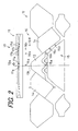
- Fig. 2 shows the outline of the cam mechanism, which is drive means for driving the operation of the movable yarn guide 1 and the knitting needle 8 as illustrated in Figs. 1A to 1D .
- the cam mechanisms are mounted on the carriages, and each include a yarn guide cam 11 and a needle main body cam 12.
- the needle main body cam 12 drives the needle main body 8a.
- a slider cam for driving the slider 8b is also provided, this cam is not shown in Fig. 2 .
- the yarn guide cam 11 is mounted on a carriage provided on the upper needle bed 3
- the needle main body cam 12 for driving the lower knitting needle 8 is provided on a carriage for driving the lower needle bed 4.
- the yarn guide cam 11 and the needle main body cam 12 are shown as components provided on the same carriage.
- the needle main body cam 12 is symmetrically disposed with respect to a center 13a of an upper cam 13.
- Stitch cams 14 are arranged on the left and right sides of the upper cam 13.
- a position of the stitch cam 14 on the downstream side in the travel direction of the carriage can be changed, and a needle main body drive butt 15 can pull the needle main body 8a toward a side of the needle bed 4 to the lower end of the inclined face obtained by the change.
- the needle main body drive butt 15 is provided on the needle main body 8a or a jack that is connected to the needle main body 8a.
- the slider 8b is moved in accordance with the position of a slider drive butt 16 that is provided on the slider 8b itself or a jack connected thereto.
- the slider cam is not shown in Fig. 2 .
- a yarn guide drive butt 17 is guided by the yarn guide cam 11, and thus the movable yarn guide 1 is driven to move forward and backward with respect to the needle bed gap 5.
- Positions 15a and 16a; 15b and 16b; 15c and 16c; and 15d and 16d of the needle main body drive butt 15 and the slider drive butt 16 in Fig. 2 respectively correspond to the states shown in Figs. 1A, 1B , 1C, and 1D .
- Positions 17a, 17b, 17c, and 17d of the yarn guide drive butt 17 are also shown as positions respectively corresponding to Figs. 1A, 1B , 1C, and 1D .
- the yarn guide drive butt 17 corresponds to each of the movable yarn guides 1 provided on both sides of the adjacent knitting needle 8. In the yarn guide drive butt 17c corresponding to the position shown in Fig. 1C , when the carriage travels from right to left in Fig.
- the right side driven first serves as the position where pulling into the needle bed 4 starts first.
- the yarn guide drive butts 17b and 17c have moved forward to the farthest position toward a side of the needle bed gap.
- the forward movement of the yarn guide drive butt 17a is made slightly smaller.
- Fig. 3 shows the overall cross-sectional configuration in the vicinity of the needle bed gap 5 in the weft knitting machine 2. Needle plates 18 and 19 are arranged side by side on the respective needle beds 3 and 4, and the needle grooves for accommodating the knitting needles 7 and 8 are formed between the needle plates 18 and 19. The upper portions of the lower needle plates 19 are extended to connect the upper and lower needle beds 3 and 4. As in the description of Figs. 1A to 1D , the needle main body drive butt 15 and the slider drive butt 16 are described with reference to the lower knitting needle 8, but it will be appreciated that these butts are provided in a similar manner also for the upper knitting needle 7.
- the needle main body 7a, 8a and the slider 7b, 8b are moved forward and backward from the needle bed 3, 4 with respect to the needle bed gap 5, the hook 7c, 8c at the front end of the needle main body 7a, 8a receives a knitting yarn fed from the yarn feeding port 10a in the needle bed gap 5, the hook 7c, 8c of the needle main body 7a, 8a is pulled into the needle bed 3, 4, and thus a knitted loop is formed.
- the front end of the needle bed 3, 4 is provided with the sinker 6 for forming a sinker loop.
- the movable yarn guide 1 moves forward and backward together with the knitting needle 7, 8 with respect to the needle bed gap 5, to guide a knitting yarn to the hook 7c, 8c.
- the weft knitting machine 2 with the movable yarn guide 1 includes the yarn guide cam 11 as drive means for driving the movable yarn guide 1 forward and backward with respect to the needle bed gap 5 in conjunction with the knitting needle 7, 8.
- the drive means makes the forward movement of the movable yarn guide 1 to the needle bed gap 5 smaller, or does not allow the forward movement, and thus feeding of a knitting yarn is not hampered.
- the movable yarn guide 1 is driven such that the guide portion 1a at the front end facing the needle bed gap 5 is moved backward from the needle bed gap 5 to the position where the sinker 6 forms a sinker loop, and thus a sinker loop can be reliably formed at the stitch determination position of the sinker 6.
- Figs. 4 and 5 show states in which the lower knitting needle 8 and the upper knitting needle 7 are driven.
- the lower knitting needle 8 is driven as shown in Figs. 1A to 1D and 2 .
- the upper knitting needle 7 is driven in a basically similar manner to that of the lower knitting needle 8.
- the sinker 6 is provided with the recess 6a, and thus a knitting yarn can be stably held at the stitch determination position for both of the upper knitting needle 7 and the lower knitting needle 8.
- the movable yarn guide 1 when the movable yarn guide 1 is pulled to move backward from the needle bed gap 5, the shape of the guide portion 1a at the front end facing the needle bed gap 5 is at least partially matched to the shape of the sinker 6 such that the guide portion 1a is continued to the recess 6a, and thus knitted loops can be formed with the plurality of knitting yarns in the same condition. Even when the recess 6a of the sinker 6 allows the slider 7b, 8b to easily project to the needle bed gap 5, the movable yarn guide 1 can prevent a knitting yarn from being caught by the slider 7b, 8b.
- Fig. 6 shows the configuration of the upper needle bed 3 viewed from above in the vicinity of the needle bed gap 5.
- the knitting needle 7 is accommodated in a needle groove 20 between the needle plates 18.
- the front end of the needle bed 3 facing the needle bed gap 5 is provided with the front edge 6b of the sinker 6 supported on and extending from the lower needle bed.
- the sinker 6 is held and supported by a needle support 21.
- the guide portion 1a at the front end of the movable yarn guide 1 is guided along a groove-like path 6c formed in the middle of the thickness of the sinker 6, and moves forward to the needle bed gap 5.
- the movable yarn guide 1 moves forward and backward with respect to the needle bed gap 5 while at least a part of the movable yarn guide 1 slides along the sinker 6, and the path 6c for accommodating the movable yarn guide 1 is formed in the sinker 6 such that the portion in which the movable yarn guide 1 and the sinker 6 slide along each other has the total thickness that is the same as the plate-like sinker 6.
- the movable yarn guide 1 and the sinker 6 integrally operate to form a sinker loop, and act as a sinker 6 having a uniform total thickness.
- a sinker loop as in the case where only the sinker 6 is used can be formed.
- the movable yarn guides 1 and the sinkers 6 are arranged on both sides of each of the knitting needles 7 and 8 at equal intervals, it is possible to eliminate a difference caused by the travel direction of the carriage when the carriage travels along the needle beds 3 and 4 to knit a fabric.
- a pitch called 3 to 8 G at which 3 to 8 knitting needles are arranged per 25.4 mm (1 inch) is preferable in order to secure a sufficient plate thickness of the sinker 6.
- [a], [b], [c], and [d] respectively show states of the knitting yarn 10b fed to the hook 7c, in correspondence with a, b, c, and d in Fig. 2 .
- [e] shows a stitch determination state.
- the guide portion 1a of the movable yarn guide 1 has moved forward to the farthest position in the needle bed gap 5.
- the knitting yarn 10b may be caught by the tongue 7d of the slider 7b as indicated by the dashed double dotted line.
- the knitting yarn 10b can be kept away from the tongue 7d as indicated by the solid line.
- Figs. 8A and 8B show the overall shape of the movable yarn guide 1.
- Fig. 8A is a plan view thereof
- Fig. 8B is a side view thereof.
- the front end portion of the movable yarn guide 1 including the guide portion 1a is formed thin so as to be accommodated inside the path 6c of the sinker 6 shown in Fig. 6 .
- Figs. 9A and 9B show the overall shape of the sinker 6.
- Fig. 9A is a side view thereof
- Fig. 9B is a front view thereof.
- the side of the sinker 6 facing the needle bed gap 5 is provided with the recess 6a, and a groove serving as the path 6c is formed in the upper half of the recess 6a.
- a hole 6d through which the wire material 9 passes is formed in the lower half of the recess 6a.
- a hole 6e used for connection to the lower needle bed 4 is formed in the vicinity of the lower end of the sinker 6.
- the positioning of the sinker 6 is performed at a groove 6f.
- Figs. 10A and 10B show the reason why the sinker 6 is provided with the recess 6a, and the reason why the movable yarn guide 1 has the above-described shape.
- Fig. 10A shows an example in which the sinker 6 is provided with the recess 6a, and a conventional movable yarn guide 22 such as the movable yarn guide member in JP-B2 3333304 is used instead of the movable yarn guide 1.
- a plurality of knitting yarns 23 in multiple yarn stitch or the like can be collected at a desired stitch determination position, and provided with a uniform loop length.
- the lower end of the guide portion 1a is extended downward as indicated by the phantom line, and thus the guide portion 1a moves forward to the needle bed gap 5 over the tongue 8d of the slider 8b, and covers the tongue 8d as shown in Figs. 1A to 1C .
- the positions of the knitting yarns 23 in multiple yarn stitch or the like are easily spread, and thus the lengths of loops formed between the fixed sinker 24 and the hook 8c are not uniform.
- Figs. 11A to 14B show examples of the combination of a movable yarn guide and a fixed sinker. As in Figs. 8A and 8B , Figs. 11A , 12A , 13A , and 14A show side views, and Figs. 11B , 12B , 13B , and 14B show front views.
- Figs. 11A and 11B show a configuration in which a guide portion 41a at the front end of a movable yarn guide 41 projects and withdraws with respect to the needle bed gap 5 from a path 46c that is open in the middle of the thickness of a sinker 46.
- the sinker 46 can be made of two plates attached to each other, in order to form the path 46c in the middle of the thickness.
- Figs. 12A and 12B show a configuration in which the lower end of a movable yarn guide 51 is provided with a groove 51a, the upper end of a sinker 56 is provided with a protruding ridge 56a, and the groove 51a is engaged with the protruding ridge 56a.
- Figs. 13A and 13B show a configuration in which a front end portion 61a of a movable yarn guide 61 is made thin, and a step 66a is formed on one side in a sinker 66 and combined with the front end portion 61a.
- the movable yarn guides 61 cannot be arranged at equal intervals even when the sinkers 66 are arranged on both sides of each knitting needle at equal intervals, but processing is easy.
- Figs. 14A and 14B show a configuration in which the lower end of a movable yarn guide 71 is provided with a protruding ridge 71a, the upper end of a sinker 76 is provided with a groove 76a, and the protruding ridge 71a is engaged with the groove 76a.
- the portion in which the movable yarn guide 51, 61, and 71 is engaged with the sinker 56, 66, and 76 has to be produced precisely without a gap or the like such that the portion does not catch a thin knitting needle in multiple stitch or the like when the movable yarn guide and the sinker integrally act to perform stitch determination of the sinker.
- the four-bed weft knitting machine 2 has been described in which the two pairs of upper and lower needle beds 3 and 4 are provided so as to be opposed to each other in a state where the needle bed gap 5 is interposed therebetween. That is to say, in the four-bed weft knitting machine 2, the two upper and lower needle beds 3 and 4 are respectively provided with the sliders 7b and 8b. Even when the sliders 7b and 8b project to the vicinity of the needle bed gap 5, the movable yarn guide 1 can prevent a knitting yarn from being caught, and thus a fabric with no damage can be knitted.
- a single-stage needle bed it is possible to avoid damage to a fabric by preventing a knitting yarn from being caught by a slider, using the movable yarn guide 1.
- a weft knitting machine provided with a movable yarn guide includes drive means for driving the movable yarn guide forward and backward with respect to a needle bed gap in conjunction with a knitting needle.
- the drive means moves the movable yarn guide forward to the needle bed gap.
- the knitting yarn can be guided to be hooked by the hook of the needle main body.
- the drive means drives the front end of the movable yarn guide backward from the needle bed gap to the position where the sinker forms a sinker loop.
- the sinker loop can be reliably formed at the stitch determination position of the sinker.
- the shape of the front end facing the needle bed gap is at least partially matched to the shape of the front end on the needle bed gap side of the sinker such that the movable yarn guide is continued to the recess.
- knitted loops can be formed with the plurality of knitting yarns in the same condition. Even when the recess of the sinker allows a slider to project to the needle bed gap, or, although not projecting, to move closer to and easily catch a knitting yarn, since the movable yarn guide can cover the front end of the slider, the knitting yarn can be kept away from the front end of the slider and prevented from being caught.
- the movable yarn guide and the sinker integrally operate to form a sinker loop, and act as a plate-like sinker having a uniform total thickness.
- a sinker loop as in the case where only the sinker is used can be formed.
- a concavity in which they are fitted to each other are formed.
- the sinker can mechanically support the movable yarn guide, and guide the back-and-forth movement of the movable yarn guide with respect to the needle bed gap.
- the drive means does not allow the movable yarn guide to move forward to the needle bed gap, or makes the amount of the forward movement smaller than that in the vicinity of the position where the knitting yarn is received by the hook.
- the front end of the movable yarn guide can cover the front end of the slider.
- a four-bed weft knitting machine is used in which two upper and lower needle beds are respectively provided with sliders. Even when the slider projects to the vicinity of the needle bed gap, the movable yarn guide can prevent a knitting yarn from being caught, and thus a fabric with no damage can be knitted.
Landscapes
- Engineering & Computer Science (AREA)
- Textile Engineering (AREA)
- Knitting Machines (AREA)
Abstract
Description
- The present invention relates to a weft knitting machine provided with a movable yarn guide that moves forward and backward together with a knitting needle with respect to a needle bed gap and that guides a knitting yarn to a hook of the knitting needle.
- Conventionally, in a weft knitting machine, knitting needles are moved forward and backward with respect to a needle bed gap from needle beds that are opposed to each other so that the needle bed gap is interposed therebetween, a knitting yarn is fed from above the needle bed gap to the hooks of the knitting needles, and thus a fabric is knitted. In the needle bed gap, a knitting yarn is fed from a yarn feeding port of a yarn feeding member such as a yarn feeder in the vicinity of the center portion of the needle bed gap, in a state where a hook of a knitting needle has been moved forward to a far position in the needle bed gap. The hook of the knitting needle that has been moved forward to the needle bed gap catches a knitting yarn when the knitting needle is moved backward from the needle bed gap and pulled into the needle bed. The knitting needles form knitted loops by pulling a knitting yarn into the needle bed along needle grooves that are provided on the needle bed. The knitting loops are composed of needle loops that are formed by the hooks of the knitting needles pulling the knitting yarn into the needle bed and sinker loops that are formed by sinkers positioned between the adjacent knitting needles and facing the needle bed gap. The size of formed knitted loops is determined by stitch density to which is related pulling the hooks of the knitting needles into the needle bed. At the time of stitch determination, the position of the sinkers facing the needle bed gap serves as a reference.
- For example, as disclosed in Japanese Examined Patent Publication
JP-B2 3333304 JP-B2 3333304 - Furthermore, as the knitting needle, a compound needle is used in which a needle main body and a slider are separated, and a hook provided at the front end of the needle main body is opened and closed with the slider. In the compound needle, the needle main body and the slider are independently driven, and the slider remains in the vicinity of the front end of the needle bed during a period in which the hook of the needle main body has moved forward to the needle bed gap. It should be noted that when the needle main body moves forward to a knit position in the needle bed gap, an already-formed-knitted loop remains on the slider as a previous loop. When a new loop is hooked on the hook and the hook is pulled into the needle bed, the hook is closed with the slider, the previous loop is knocked-over, and a fabric is knitted. Thus, when the needle main body has moved forward to the needle bed gap, it is necessary for the slider to move forward to the vicinity of the needle bed gap such that the knocked-over previous loop can easily escape to the needle bed gap. Herein, in a case where a knitting yarn before hooked on the hook is caught by the slider, the knitting yarn may be not hooked on the hook. The movable yarn guide such as the movable guide member also has an action of preventing a knitting yarn from being caught by the slider.
- In the weft knitting machine, the needle beds are opposed to each other so that the needle bed gap is interposed therebetween. The reason for this is to make it possible to knit a fabric in so-called rib knitting or rib stitch using knitting needles of both needle beds, by knitting face stitches and back stitches of stitches with the knitting needles of the respective needle beds, and to knit various fabric patterns also using stitch transferring. Recently, tubular fabrics have been also knitted using both needle beds.
- Furthermore, for example, as disclosed in Japanese Examined Patent Publication
JP-B2 7-96740 (1995 JP-B2 7-96740 - In a weft knitting machine, as a knitting yarn, it is also required to use various fancy yarns called, for example, fancy twisted yarns. Examples of the fancy twisted yarns include knot yarns in which knots are formed at intervals and loop yarns in which loops made of a wound yarn are continuously wound around a core yarn.
Interlaced yarns are also used that are produced by interlacing yarns through an air-jet. These yarns occupy a larger space than ordinary twisted knitting yarns.
Thus, when a part of these yarns is hooked on a hook and pulled into a needle bed, these yarns are easily caught by a slider or the like in the vicinity of a stitch determination position. - Moreover, there is a case in which knitting is performed simultaneously using a plurality of knitting yarns, and examples thereof include plating stitch that uses two knitting yarns and multiple yarn stitch that uses a larger number of thin knitting yarns. When this sort of knitting yarn is used, as a sinker, a fixed sinker having a recess is used such that the position of a knitting yarn is stable at the time of stitch determination. However, in a case where the sinker has a recess, the recess allows the slider to easily project or move closer to the needle bed gap, and thus a knitting yarn is more easily caught by the slider. The movable yarn guide member as described in
JP-B2 3333304 - In a case where even a part of a fancy twisted yarn or a knitting yarn in multiple yarn stitch is caught by the slider, the caught portion is damaged, and the fabric that is being knitted also may be damaged. Furthermore, in a case where double-stage needle beds are provided as in a four-bed weft knitting machine, the forward movement of the slider with respect to the needle bed gap is more complicated than the case of a single-stage needle bed, and thus a knitting yarn is more easily caught.
- It is an object of the invention to provide a weft knitting machine with a movable yarn guide that can guide a knitting yarn to a hook in a needle bed gap the same as a conventional movable yarn guide member and that can prevent damage to a fabric due to undesired catch of a knitting yarn.
- The invention is directed to a weft knitting machine with a movable yarn guide in which a knitting needle is a compound needle comprising a needle main body and a slider, the needle main body is moved forward and backward with respect to a needle bed gap, a hook at a front end of the needle main body receives a knitting yarn fed from a yarn feeding port, a sinker for forming a sinker loop when forming a knitted loop by pulling the hook into a needle bed is provided on the needle bed gap side on the needle bed, and the movable yarn guide moves forward and backward together with the knitting needle with respect to the needle bed gap to guide a knitting yarn to the hook, the weft knitting machine comprising:
- drive means for driving the movable yarn guide forward and backward with respect to the needle bed gap, the drive means driving the movable yarn guide in conjunction with the knitting needle such that in the vicinity of a position where the needle main body starts to be pulled into the needle bed and a knitting yarn is received by the hook, the movable yarn guide is moved forward to the needle bed gap, and such that when the needle main body is pulled into the needle bed and a knitted loop is formed by the hook and a front end of the sinker, a front end of the movable yarn guide facing the needle bed gap is moved backward from the needle bed gap to the position of the front end of the sinker forming a sinker loop,
- Furthermore, in the invention, it is preferable that in the sinker, a portion facing the needle bed gap and forming the sinker loop is in a shape of a plate,
the movable yarn guide moves forward and backward with respect to the needle bed gap while at least a part of the movable yarn guide slides along the sinker, and
in the portion where the movable yarn guide and the sinker slide along each other, a concavity in which the sinker and the movable yarn guide are fitted to each other is formed such that its total thickness is the same as a thickness of the plate-like sinker. - Furthermore, in the invention, it is preferable that in the vicinity of a position where the needle main body has moved forward to the needle bed gap and a knitting yarn is fed from the yarn feeding port, the drive means makes an amount of the forward movement of the movable yarn guide to the needle bed gap smaller than that in the vicinity of a position where the knitting yarn is received by the hook.
- Furthermore, in the invention, it is preferable that the weft knitting machine is a four-bed weft knitting machine in which two pairs of upper and lower needle beds are provided so as to be opposed to each other in a state where the needle bed gap is interposed therebetween.
- Other and further objects, features, and advantages of the invention will be more explicit from the following detailed description taken with reference to the drawings.
-
Figs. 1A to 1D are simplified side cross-sectional views showing an operation of amovable yarn guide 1, in aweft knitting machine 2 with themovable yarn guide 1 according to one embodiment of the invention. -
Fig. 2 is a plan view showing an outline of cam mechanism, which is drive means for driving the operation of themovable yarn guide 1 and a knittingneedle 8 as illustrated inFigs. 1A to 1D . -
Fig. 3 is an overall side cross-sectional view in the vicinity of aneedle bed gap 5 in aweft knitting machine 2 inFigs. 1A to 1D . -
Fig. 4 is a side cross-sectional view showing states in which alower knitting needle 8 is driven in theweft knitting machine 2 inFigs. 1A to 1D . -
Fig. 5 is a side cross-sectional view showing states in which an upper knittingneedle 7 is driven in theweft knitting machine 2 inFigs. 1A to 1D . -
Fig. 6 is a plan view showing a configuration of anupper needle bed 3 in the vicinity of theneedle bed gap 5 in theweft knitting machine 2 inFigs. 1A to 1D . -
Fig. 7 is a plan view showing states of aknitting yarn 10b fed to ahook 7c, in correspondence with a, b, c, and d inFig. 2 . -
Figs. 8A and 8B are a plan view and a side view showing an overall shape of themovable yarn guide 1 used for theweft knitting machine 2 inFigs. 1A to 1D , respectively. -
Figs. 9A and 9B are a side view and a front view showing an overall shape of asinker 6 used for theweft knitting machine 2 inFigs. 1A to 1D , respectively. -
Figs. 10A and 10B are simplified side cross-sectional views showing a reason why thesinker 6 is provided with arecess 6a, and a reason why themovable yarn guide 1 has such a shape. -
Figs. 11A and 11B are a side view and a front view showing examples of a combination of amovable yarn guide 41 and a fixedsinker 46, respectively. -
Figs. 12A and 12B are a side view and a front view showing examples of a combination of amovable yarn guide 51 and a fixedsinker 56, respectively. -
Figs. 13A and 13B are a side view and a front view showing examples of a combination of amovable yarn guide 61 and a fixedsinker 66, respectively. -
Figs. 14A and 14B are a side view and a front view showing examples of a combination of amovable yarn guide 71 and a fixedsinker 76, respectively. - Now referring to the drawings, preferred embodiments of the invention are described below.
-
Figs. 1A to 1D are side views showing the operation of amovable yarn guide 1, in aweft knitting machine 2 with amovable yarn guide 1 according to one embodiment of the invention. Theweft knitting machine 2 is a four-bed weft knitting machine in which two pairs of upper andlower needle beds needle bed gap 5 is interposed therebetween. The two pairs ofneedle beds virtual center plane 5a in theneedle bed gap 5 extending in a vertical direction. In theweft knitting machine 2, a side on which the front pair of theneedle beds needle beds movable yarn guide 1 is provided on theupper needle bed 3. A fixedsinker 6 is supported on thelower needle bed 4. Thesinker 6 is provided with arecess 6a used for precisely performing stitch determination for knitting yarns in multiple yarn stitch or the like. On the upper andlower needle beds knitting needles needle bed gap 5. Theknitting needles main bodies sliders main bodies hooks sliders tongues hooks - Each of the
needle beds needle beds knitting needles needle beds knitting needles movable yarn guide 1 forward and backward with respect to theneedle bed gap 5. Herein, when theknitting needles lower needle beds lower knitting needles knitting needles lower needle beds needle bed gap 5 is substantially formed by awire material 9 such as a piano wire passing through in the longitudinal direction. -
Fig. 1A shows a state in which theknitting needle 8 has moved forward from thelower needle bed 4 to a knit position, for example. Thehook 8c of the needlemain body 8a moves forward to a farther position in theneedle bed gap 5 than the position where a knitting yarn is fed from ayarn feeding port 10a of ayarn feeder 10 in the vicinity of thecenter plane 5a in theneedle bed gap 5. Theyarn feeder 10 is brought by the carriage. The cam mechanism drives theknitting needle hook main body needle bed gap 5, thehook yarn feeding port 10a of theyarn feeder 10. Thetongue 8d of theslider 8b moves forward to theneedle bed gap 5 to the vicinity of therecess 6a of thesinker 6. Aguide portion 1a at the front end of themovable yarn guide 1 is longer than the movable yarn guide member inJP-B2 3333304 guide portion 1a can cover thetongue 8d. It is possible to move theguide portion 1a at the front end of themovable yarn guide 1 forward to theneedle bed gap 5 over afront edge 6b of thesinker 6, thereby preventing a knitting yarn from being caught by thetongue 8d of theslider 8b. Not moving theguide portion 1a of themovable yarn guide 1 forward to theneedle bed gap 5 does not cause any problem. However, it is preferable to move theguide portion 1a forward within a range in which theguide portion 1a does not interfere with theyarn feeding port 10a, in order to prevent a yarn from being caught even when the yarn swings as in the case of a fancy twisted yarn or the like. -
Fig. 1B shows a state in which the cam mechanism of the carriage is about to pull the needlemain body 8a into theneedle bed 4. When the needlemain body 8a is pulled from theneedle bed gap 5 into theneedle bed 4, the movement range of thehook 8c includes a feeding height at which a yarn can be fed, that is, aknitting yarn 10b is fed from theyarn feeding port 10a of theyarn feeder 10 shown inFig. 1A . Thus, theknitting yarn 10b has not been pulled yet, and can be pulled from this state. It is possible to catch theknitting yarn 10b at thehook 7c, by pulling the needlemain body 8a into theneedle bed 4. Since themovable yarn guide 1 moves forward to the farthest position in theneedle bed gap 5 and guides theknitting yarn 10b in such a manner that theguide portion 1a pushes theknitting yarn 10b into thehook 8c, thehook 8c can reliably catch theknitting yarn 10b. Furthermore, since the portion of theguide portion 1a extending downward covers the front end of thetongue 8d of theslider 8b, theknitting yarn 10b is kept away from thetongue 8d, and thus theknitting yarn 10b can be prevented from being caught by thetongue 8d. -
Fig. 1C shows a state in which the needlemain body 8a is pulled into theneedle bed 4, and thehook 8c is closed by thetongue 8d of theslider 8b. In a case where a previous loop is held by thetongue 8d, knock-over is performed in which theknitting needle 8 is further pulled into theneedle bed 4 to cause the previous loop to surmount a new loop inside theclosed hook 8c and escape to theneedle bed gap 5. Themovable yarn guide 1 has moved forward to theneedle bed gap 5 to the position where thehook 8c is closed by thetongue 8d, and thus a knitting yarn can be continuously prevented from being caught. -
Fig. 1D shows a state in which theknitting needle 8 has been pulled into theneedle bed 4 and stitch determination is performed. Theguide portion 1a of themovable yarn guide 1 moves backward to a stitch determination position that is matched to thefront edge 6b of thesinker 6, and a new knitted loop is formed between thehook 8c, and thefront edge 6b of thesinker 6 and theguide portion 1a of themovable yarn guide 1. -
Fig. 2 shows the outline of the cam mechanism, which is drive means for driving the operation of themovable yarn guide 1 and theknitting needle 8 as illustrated inFigs. 1A to 1D . The cam mechanisms are mounted on the carriages, and each include ayarn guide cam 11 and a needlemain body cam 12. The needlemain body cam 12 drives the needlemain body 8a. Although a slider cam for driving theslider 8b is also provided, this cam is not shown inFig. 2 . Furthermore, as described later, theyarn guide cam 11 is mounted on a carriage provided on theupper needle bed 3, and the needlemain body cam 12 for driving thelower knitting needle 8 is provided on a carriage for driving thelower needle bed 4. However, for the sake of convenience of this description, theyarn guide cam 11 and the needlemain body cam 12 are shown as components provided on the same carriage. - The needle
main body cam 12 is symmetrically disposed with respect to acenter 13a of anupper cam 13.Stitch cams 14 are arranged on the left and right sides of theupper cam 13. A position of thestitch cam 14 on the downstream side in the travel direction of the carriage can be changed, and a needle mainbody drive butt 15 can pull the needlemain body 8a toward a side of theneedle bed 4 to the lower end of the inclined face obtained by the change. The needle mainbody drive butt 15 is provided on the needlemain body 8a or a jack that is connected to the needlemain body 8a. Theslider 8b is moved in accordance with the position of aslider drive butt 16 that is provided on theslider 8b itself or a jack connected thereto. Herein, as described above, the slider cam is not shown inFig. 2 . A yarnguide drive butt 17 is guided by theyarn guide cam 11, and thus themovable yarn guide 1 is driven to move forward and backward with respect to theneedle bed gap 5. -
Positions 15a and 16a; 15b and 16b; 15c and 16c; and 15d and 16d of the needle mainbody drive butt 15 and theslider drive butt 16 inFig. 2 respectively correspond to the states shown inFigs. 1A, 1B ,1C, and 1D .Positions guide drive butt 17 are also shown as positions respectively corresponding toFigs. 1A, 1B ,1C, and 1D . Herein, the yarnguide drive butt 17 corresponds to each of the movable yarn guides 1 provided on both sides of theadjacent knitting needle 8. In the yarn guide drive butt 17c corresponding to the position shown inFig. 1C , when the carriage travels from right to left inFig. 2 , the right side driven first serves as the position where pulling into theneedle bed 4 starts first. At the positions corresponding toFigs. 1B and1C , the yarn guide drive butts 17b and 17c have moved forward to the farthest position toward a side of the needle bed gap. On the other hand, in the vicinity of the position where a knitting yarn fed from theyarn feeding port 10a is received as shown inFig. 1A , the forward movement of the yarnguide drive butt 17a is made slightly smaller. -
Fig. 3 shows the overall cross-sectional configuration in the vicinity of theneedle bed gap 5 in theweft knitting machine 2.Needle plates respective needle beds knitting needles needle plates lower needle plates 19 are extended to connect the upper andlower needle beds Figs. 1A to 1D , the needle mainbody drive butt 15 and theslider drive butt 16 are described with reference to thelower knitting needle 8, but it will be appreciated that these butts are provided in a similar manner also for theupper knitting needle 7. - As described above, in the
weft knitting machine 2, the needlemain body slider needle bed needle bed gap 5, thehook main body yarn feeding port 10a in theneedle bed gap 5, thehook main body needle bed needle bed sinker 6 for forming a sinker loop. Themovable yarn guide 1 moves forward and backward together with theknitting needle needle bed gap 5, to guide a knitting yarn to thehook weft knitting machine 2 with themovable yarn guide 1 includes theyarn guide cam 11 as drive means for driving themovable yarn guide 1 forward and backward with respect to theneedle bed gap 5 in conjunction with theknitting needle main body needle bed gap 5 and a knitting yarn is fed from theyarn feeding port 10a, the drive means makes the forward movement of themovable yarn guide 1 to theneedle bed gap 5 smaller, or does not allow the forward movement, and thus feeding of a knitting yarn is not hampered. When thefront end 1a of themovable yarn guide 1 has moved forward to theneedle bed gap 5 over the front end of theslider slider main body needle bed hook movable yarn guide 1 is moved forward to the farther position in theneedle bed gap 5, and thus the knitting yarn can be reliably caught by thehook main body main body needle bed hook front edge 6b of thesinker 6, themovable yarn guide 1 is driven such that theguide portion 1a at the front end facing theneedle bed gap 5 is moved backward from theneedle bed gap 5 to the position where thesinker 6 forms a sinker loop, and thus a sinker loop can be reliably formed at the stitch determination position of thesinker 6. -
Figs. 4 and5 show states in which thelower knitting needle 8 and theupper knitting needle 7 are driven. Thelower knitting needle 8 is driven as shown inFigs. 1A to 1D and2 . Theupper knitting needle 7 is driven in a basically similar manner to that of thelower knitting needle 8. Thesinker 6 is provided with therecess 6a, and thus a knitting yarn can be stably held at the stitch determination position for both of theupper knitting needle 7 and thelower knitting needle 8. Even in a case where thesinker 6 is provided with therecess 6a in order to use knitting yarns in multiple yarn stitch, when themovable yarn guide 1 is pulled to move backward from theneedle bed gap 5, the shape of theguide portion 1a at the front end facing theneedle bed gap 5 is at least partially matched to the shape of thesinker 6 such that theguide portion 1a is continued to therecess 6a, and thus knitted loops can be formed with the plurality of knitting yarns in the same condition. Even when therecess 6a of thesinker 6 allows theslider needle bed gap 5, themovable yarn guide 1 can prevent a knitting yarn from being caught by theslider -
Fig. 6 shows the configuration of theupper needle bed 3 viewed from above in the vicinity of theneedle bed gap 5. Theknitting needle 7 is accommodated in aneedle groove 20 between theneedle plates 18. The front end of theneedle bed 3 facing theneedle bed gap 5 is provided with thefront edge 6b of thesinker 6 supported on and extending from the lower needle bed. Thesinker 6 is held and supported by aneedle support 21. Theguide portion 1a at the front end of themovable yarn guide 1 is guided along a groove-like path 6c formed in the middle of the thickness of thesinker 6, and moves forward to theneedle bed gap 5. More specifically, at least the portion of thesinker 6 facing theneedle bed gap 5 and forming a sinker loop is in the shape of a plate, themovable yarn guide 1 moves forward and backward with respect to theneedle bed gap 5 while at least a part of themovable yarn guide 1 slides along thesinker 6, and thepath 6c for accommodating themovable yarn guide 1 is formed in thesinker 6 such that the portion in which themovable yarn guide 1 and thesinker 6 slide along each other has the total thickness that is the same as the plate-like sinker 6. At the stitch determination position of thesinker 6, themovable yarn guide 1 and thesinker 6 integrally operate to form a sinker loop, and act as asinker 6 having a uniform total thickness. Thus, a sinker loop as in the case where only thesinker 6 is used can be formed. In particular, in a case where the movable yarn guides 1 and thesinkers 6 are arranged on both sides of each of theknitting needles needle beds weft knitting machine 2, a pitch called 3 to 8 G at which 3 to 8 knitting needles are arranged per 25.4 mm (1 inch) is preferable in order to secure a sufficient plate thickness of thesinker 6. - In
Fig. 7 , [a], [b], [c], and [d] respectively show states of theknitting yarn 10b fed to thehook 7c, in correspondence with a, b, c, and d inFig. 2 .
Furthermore, [e] shows a stitch determination state. As described above, at the positions [b] and [c], theguide portion 1a of themovable yarn guide 1 has moved forward to the farthest position in theneedle bed gap 5. Herein, in a case where the lower end of theguide portion 1a of themovable yarn guide 1 does not extend downward as in the movable yarn guide member inJP-B2 3333304 knitting yarn 10b may be caught by thetongue 7d of theslider 7b as indicated by the dashed double dotted line. With theguide portion 1a of themovable yarn guide 1, theknitting yarn 10b can be kept away from thetongue 7d as indicated by the solid line. -
Figs. 8A and 8B show the overall shape of themovable yarn guide 1.Fig. 8A is a plan view thereof, andFig. 8B is a side view thereof. The front end portion of themovable yarn guide 1 including theguide portion 1a is formed thin so as to be accommodated inside thepath 6c of thesinker 6 shown inFig. 6 . -
Figs. 9A and 9B show the overall shape of thesinker 6.Fig. 9A is a side view thereof, andFig. 9B is a front view thereof. The side of thesinker 6 facing theneedle bed gap 5 is provided with therecess 6a, and a groove serving as thepath 6c is formed in the upper half of therecess 6a. Ahole 6d through which thewire material 9 passes is formed in the lower half of therecess 6a. Ahole 6e used for connection to thelower needle bed 4 is formed in the vicinity of the lower end of thesinker 6. The positioning of thesinker 6 is performed at agroove 6f. -
Figs. 10A and 10B show the reason why thesinker 6 is provided with therecess 6a, and the reason why themovable yarn guide 1 has the above-described shape.Fig. 10A shows an example in which thesinker 6 is provided with therecess 6a, and a conventionalmovable yarn guide 22 such as the movable yarn guide member inJP-B2 3333304 movable yarn guide 1. With therecess 6a of thesinker 6, a plurality of knitting yarns 23 in multiple yarn stitch or the like can be collected at a desired stitch determination position, and provided with a uniform loop length. Herein, in a state where thetongue 8d of theslider 8b moves forward or closer to theneedle bed gap 5, there is a fear of catching the knitting yarns 23 by the front end of thetongue 8d. In themovable yarn guide 1 of this embodiment, the lower end of theguide portion 1a is extended downward as indicated by the phantom line, and thus theguide portion 1a moves forward to theneedle bed gap 5 over thetongue 8d of theslider 8b, and covers thetongue 8d as shown inFigs. 1A to 1C . Herein, with a fixed sinker 24 without a recess as shown inFig. 10B , the positions of the knitting yarns 23 in multiple yarn stitch or the like are easily spread, and thus the lengths of loops formed between the fixed sinker 24 and thehook 8c are not uniform. -
Figs. 11A to 14B show examples of the combination of a movable yarn guide and a fixed sinker. As inFigs. 8A and 8B ,Figs. 11A ,12A ,13A , and14A show side views, andFigs. 11B ,12B ,13B , and14B show front views. -
Figs. 11A and 11B show a configuration in which aguide portion 41a at the front end of amovable yarn guide 41 projects and withdraws with respect to theneedle bed gap 5 from apath 46c that is open in the middle of the thickness of asinker 46. Thesinker 46 can be made of two plates attached to each other, in order to form thepath 46c in the middle of the thickness. -
Figs. 12A and 12B show a configuration in which the lower end of amovable yarn guide 51 is provided with agroove 51a, the upper end of asinker 56 is provided with a protrudingridge 56a, and thegroove 51a is engaged with the protrudingridge 56a. -
Figs. 13A and 13B show a configuration in which afront end portion 61a of amovable yarn guide 61 is made thin, and astep 66a is formed on one side in asinker 66 and combined with thefront end portion 61a. With this configuration, the movable yarn guides 61 cannot be arranged at equal intervals even when thesinkers 66 are arranged on both sides of each knitting needle at equal intervals, but processing is easy. -
Figs. 14A and 14B show a configuration in which the lower end of amovable yarn guide 71 is provided with a protrudingridge 71a, the upper end of asinker 76 is provided with agroove 76a, and the protrudingridge 71a is engaged with thegroove 76a. - In the configurations in
Figs. 12A and 12B to14A and 14B , the portion in which themovable yarn guide sinker - In the foregoing embodiments, as a weft knitting machine, the four-bed
weft knitting machine 2 has been described in which the two pairs of upper andlower needle beds needle bed gap 5 is interposed therebetween. That is to say, in the four-bedweft knitting machine 2, the two upper andlower needle beds sliders sliders needle bed gap 5, themovable yarn guide 1 can prevent a knitting yarn from being caught, and thus a fabric with no damage can be knitted. Herein, also in a case where a single-stage needle bed is used, it is possible to avoid damage to a fabric by preventing a knitting yarn from being caught by a slider, using themovable yarn guide 1. - The invention may be embodied in other specific forms without departing from the spirit or essential characteristics thereof. The present embodiments are therefore to be considered in all respects as illustrative and not restrictive, the scope of the invention being indicated by the appended claims rather than by the foregoing description and all changes which come within the meaning and the range of equivalency of the claims are therefore intended to be embraced therein.
- According to the invention, a weft knitting machine provided with a movable yarn guide includes drive means for driving the movable yarn guide forward and backward with respect to a needle bed gap in conjunction with a knitting needle. In the vicinity of the position where a needle main body starts to be pulled into a needle bed and a knitting yarn is received by a hook of the needle main body, the drive means moves the movable yarn guide forward to the needle bed gap. Thus, the knitting yarn can be guided to be hooked by the hook of the needle main body. When the needle main body is pulled into the needle bed and a knitted loop is formed by the hook and the front end of a sinker, the drive means drives the front end of the movable yarn guide backward from the needle bed gap to the position where the sinker forms a sinker loop. Thus, the sinker loop can be reliably formed at the stitch determination position of the sinker. For example, even in a case where the sinker is provided with a recess in order to use knitting yarns in multiple yarn stitch, when the movable yarn guide is pulled to move backward from the needle bed gap, the shape of the front end facing the needle bed gap is at least partially matched to the shape of the front end on the needle bed gap side of the sinker such that the movable yarn guide is continued to the recess. Thus, knitted loops can be formed with the plurality of knitting yarns in the same condition. Even when the recess of the sinker allows a slider to project to the needle bed gap, or, although not projecting, to move closer to and easily catch a knitting yarn, since the movable yarn guide can cover the front end of the slider, the knitting yarn can be kept away from the front end of the slider and prevented from being caught.
- Furthermore, according to the invention, the movable yarn guide and the sinker integrally operate to form a sinker loop, and act as a plate-like sinker having a uniform total thickness. Thus, a sinker loop as in the case where only the sinker is used can be formed. In the portion where the sinker and the movable yarn guide slide along each other, a concavity in which they are fitted to each other are formed. Thus, the sinker can mechanically support the movable yarn guide, and guide the back-and-forth movement of the movable yarn guide with respect to the needle bed gap. In particular, in a case where the sinkers and the movable yarn guides are arranged on both sides of each knitting needle at equal intervals, it is possible to eliminate a difference caused by the travel direction of the carriage when'the carriage travels along the needle bed to knit a fabric.
- Furthermore, according to the invention, in the vicinity of the position where the needle main body has moved forward to the needle bed gap and a knitting yarn is fed from the yarn feeding port, the drive means does not allow the movable yarn guide to move forward to the needle bed gap, or makes the amount of the forward movement smaller than that in the vicinity of the position where the knitting yarn is received by the hook. Thus, it is possible to prevent feeding of the knitting yarn from being hampered, by preventing interference between the yarn feeding port and the movable yarn guide. The front end of the movable yarn guide can cover the front end of the slider. Thus, when the movable yarn guide is moved forward to the needle bed gap over the slider, a knitting yarn can be prevented from being caught by the slider.
- Furthermore, according to the invention, a four-bed weft knitting machine is used in which two upper and lower needle beds are respectively provided with sliders. Even when the slider projects to the vicinity of the needle bed gap, the movable yarn guide can prevent a knitting yarn from being caught, and thus a fabric with no damage can be knitted.
when the movable yarn guide is moved backward to the position of the front end of the sinker, a shape of the front end facing the needle bed gap of the movable yarn guide is at least partially matched to a shape of the front end on the needle bed gap side of the sinker continued to the recess, and the front end of the movable yarn guide can cover the front end of the slider of the knitting needle.
Claims (4)
- A weft knitting machine with a movable yarn guide in which a knitting needle is a compound needle comprising a needle main body and a slider, the needle main body is moved forward and backward with respect to a needle bed gap, a hook at a front end of the needle main body receives a knitting yarn fed from a yarn feeding port, a sinker for forming a sinker loop when forming a knitted loop by pulling the hook into a needle bed is provided on the needle bed gap side on the needle bed, and the movable yarn guide moves forward and backward together with the knitting needle with respect to the needle bed gap to guide a knitting yarn to the hook, the weft knitting machine comprising:drive means for driving the movable yarn guide forward and backward with respect to the needle bed gap, the drive means driving the movable yarn guide in conjunction with the knitting needle such that in the vicinity of a position where the needle main body starts to be pulled into the needle bed and a knitting yarn is received by the hook, the movable yarn guide is moved forward to the needle bed gap, and such that when the needle main body is pulled into the needle bed and a knitted loop is formed by the hook and a front end of the sinker, a front end of the movable yarn guide facing the needle bed gap is moved backward from the needle bed gap to the position of the front end of the sinker forming a sinker loop,wherein the front end of the sinker on the needle bed gap side forming a sinker loop is provided with a recess at which knitting yarns are collected in a case where a plurality of knitting yarns are fed, and
when the movable yarn guide is moved backward to the position of the front end of the sinker, a shape of the front end facing the needle bed gap of the movable yarn guide is at least partially matched to a shape of the front end on the needle bed gap side of the sinker continued to the recess, and the front end of the movable yarn guide can cover the front end of the slider of the knitting needle. - The weft knitting machine of claim 1, wherein in the sinker, a portion facing the needle bed gap and forming the sinker loop is in a shape of a plate,
the movable yarn guide moves forward and backward with respect to the needle bed gap while at least a part of the movable yarn guide slides along the sinker, and
in the portion where the movable yarn guide and the sinker slide along each other, a concavity in which the sinker and the movable yarn guide are fitted to each other is formed such that its total thickness is the same as a thickness of the plate-like sinker. - The weft knitting machine of claim 1 or 2, wherein, in the vicinity of a position where the needle main body has moved forward to the needle bed gap and a knitting yarn is fed from the yarn feeding port, the drive means makes an amount of the forward movement of the movable yarn guide to the needle bed gap smaller than that in the vicinity of a position where the knitting yarn is received by the hook.
- The weft knitting machine of any one of claims 1 to 3, wherein the weft knitting machine is a four-bed weft knitting machine in which two pairs of upper and lower needle beds are provided so as to be opposed to each other in a state where the needle bed gap is interposed therebetween.
Applications Claiming Priority (2)
| Application Number | Priority Date | Filing Date | Title |
|---|---|---|---|
| JP2005282919 | 2005-09-28 | ||
| PCT/JP2006/319204 WO2007037285A1 (en) | 2005-09-28 | 2006-09-27 | Weft knitting machine having movable yarn guide |
Publications (3)
| Publication Number | Publication Date |
|---|---|
| EP1942216A1 true EP1942216A1 (en) | 2008-07-09 |
| EP1942216A4 EP1942216A4 (en) | 2012-08-15 |
| EP1942216B1 EP1942216B1 (en) | 2018-04-18 |
Family
ID=37899709
Family Applications (1)
| Application Number | Title | Priority Date | Filing Date |
|---|---|---|---|
| EP06810662.4A Active EP1942216B1 (en) | 2005-09-28 | 2006-09-27 | Weft knitting machine having movable yarn guide |
Country Status (4)
| Country | Link |
|---|---|
| EP (1) | EP1942216B1 (en) |
| JP (1) | JP5179878B2 (en) |
| CN (1) | CN101278086B (en) |
| WO (1) | WO2007037285A1 (en) |
Cited By (1)
| Publication number | Priority date | Publication date | Assignee | Title |
|---|---|---|---|---|
| IT202000018658A1 (en) * | 2020-07-30 | 2022-01-30 | Jvc Holding Srl | SINKER FOR KNITTING MACHINE, KNITTING MACHINE WHICH USES SUCH SINKER, AND METHOD OF CREATING A KNIT STITCH WITH SUCH SINKER |
Families Citing this family (6)
| Publication number | Priority date | Publication date | Assignee | Title |
|---|---|---|---|---|
| CN101778970B (en) * | 2007-07-30 | 2011-04-20 | 株式会社岛精机制作所 | Fabric knitting method, and weft knitting machine |
| WO2009016802A1 (en) * | 2007-07-30 | 2009-02-05 | Shima Seiki Mfg., Ltd. | Fabric knitting method, and weft knitting machine |
| WO2010073558A1 (en) * | 2008-12-27 | 2010-07-01 | 株式会社島精機製作所 | Weft knitting machine and stitch transfer method for same |
| JP5525344B2 (en) * | 2010-06-18 | 2014-06-18 | 株式会社島精機製作所 | Compound needle of flat knitting machine |
| CN109056178B (en) * | 2018-09-29 | 2023-09-29 | 宁波慈星股份有限公司 | Sheeting in flat knitting machine |
| JP7271398B2 (en) * | 2019-11-15 | 2023-05-11 | 株式会社島精機製作所 | Flat knitting machine for pile knitting and knitting method |
Citations (2)
| Publication number | Priority date | Publication date | Assignee | Title |
|---|---|---|---|---|
| EP0672769A1 (en) * | 1994-03-18 | 1995-09-20 | Shima Seiki Mfg., Ltd. | Flat bed knitting machine with movable yarn guide members |
| DE19806548A1 (en) * | 1998-02-17 | 1999-08-19 | Schieber Universal Maschf | Flatbed knitter with comb sinkers at the needle bed |
Family Cites Families (6)
| Publication number | Priority date | Publication date | Assignee | Title |
|---|---|---|---|---|
| KR0123800B1 (en) * | 1989-12-28 | 1997-11-27 | 마사히로 시마 | Sinker mechanism for knitting machine |
| JPH03234847A (en) * | 1990-02-09 | 1991-10-18 | Shima Seiki Seisakusho:Kk | Movable sinker in weft knitting machine |
| JPH0796740B2 (en) * | 1991-08-29 | 1995-10-18 | 株式会社島精機製作所 | Bunk bed flat knitting machine sinker |
| JP2618312B2 (en) * | 1992-07-09 | 1997-06-11 | 株式会社島精機製作所 | Sinker device in flat knitting machine |
| EP1467010B1 (en) * | 2003-04-11 | 2006-06-21 | H. Stoll GmbH & Co. | Flat knitting machine having at least two needle beds |
| JP7096740B2 (en) * | 2018-08-30 | 2022-07-06 | 株式会社山田製作所 | Steering device |
-
2006
- 2006-09-27 EP EP06810662.4A patent/EP1942216B1/en active Active
- 2006-09-27 JP JP2007537649A patent/JP5179878B2/en active Active
- 2006-09-27 WO PCT/JP2006/319204 patent/WO2007037285A1/en active Application Filing
- 2006-09-27 CN CN2006800362400A patent/CN101278086B/en active Active
Patent Citations (2)
| Publication number | Priority date | Publication date | Assignee | Title |
|---|---|---|---|---|
| EP0672769A1 (en) * | 1994-03-18 | 1995-09-20 | Shima Seiki Mfg., Ltd. | Flat bed knitting machine with movable yarn guide members |
| DE19806548A1 (en) * | 1998-02-17 | 1999-08-19 | Schieber Universal Maschf | Flatbed knitter with comb sinkers at the needle bed |
Non-Patent Citations (1)
| Title |
|---|
| See also references of WO2007037285A1 * |
Cited By (2)
| Publication number | Priority date | Publication date | Assignee | Title |
|---|---|---|---|---|
| IT202000018658A1 (en) * | 2020-07-30 | 2022-01-30 | Jvc Holding Srl | SINKER FOR KNITTING MACHINE, KNITTING MACHINE WHICH USES SUCH SINKER, AND METHOD OF CREATING A KNIT STITCH WITH SUCH SINKER |
| WO2022022882A1 (en) * | 2020-07-30 | 2022-02-03 | Jvc Holding S.R.L. | Sinker for a knitting machine, knitting machine that uses said sinker, and method for producing a knit stitch with said sinker |
Also Published As
| Publication number | Publication date |
|---|---|
| JP5179878B2 (en) | 2013-04-10 |
| WO2007037285A1 (en) | 2007-04-05 |
| EP1942216A4 (en) | 2012-08-15 |
| CN101278086A (en) | 2008-10-01 |
| CN101278086B (en) | 2010-12-08 |
| EP1942216B1 (en) | 2018-04-18 |
| JPWO2007037285A1 (en) | 2009-04-09 |
Similar Documents
| Publication | Publication Date | Title |
|---|---|---|
| EP1942216B1 (en) | Weft knitting machine having movable yarn guide | |
| EP1972706B1 (en) | Weft knitting machine capable of inserting warp and knitting method by that weft knitting machine | |
| US7412850B2 (en) | Complex cam system | |
| KR20060121821A (en) | Weft knitting machine with movable yarn guide member | |
| WO2006062205A1 (en) | Weft knitting machine | |
| JP4125319B2 (en) | Yarn feeder for flat knitting machine | |
| US6883352B2 (en) | Loop presser, flatbed knitting machine having loop presser, and fabric knitting method using loop presser | |
| EP2025785B1 (en) | Knitting method of intersia pattern fabric and weft knitting machine | |
| JPWO2007037285A6 (en) | Flat knitting machine with movable yarn guide | |
| EP0603006B1 (en) | A transferring jack of a flat knitting machine | |
| WO2009150825A1 (en) | Weft knitting machine equipped with movable sinker | |
| EP1655398B1 (en) | Weft knitting machine having movable sinker | |
| EP2570535B1 (en) | Flatbed knitting machine provided with compound needle, and slider control method for flatbed knitting machine | |
| JP4175978B2 (en) | Flat knitting machine with movable sinker | |
| JP2002327358A (en) | Flat knitting machine equipped with movable yarn-guiding member | |
| JP4403507B2 (en) | sewing machine | |
| JPWO2009016802A1 (en) | Knitting method of knitted fabric and flat knitting machine |
Legal Events
| Date | Code | Title | Description |
|---|---|---|---|
| PUAI | Public reference made under article 153(3) epc to a published international application that has entered the european phase |
Free format text: ORIGINAL CODE: 0009012 |
|
| 17P | Request for examination filed |
Effective date: 20080331 |
|
| AK | Designated contracting states |
Kind code of ref document: A1 Designated state(s): AT BE BG CH CY CZ DE DK EE ES FI FR GB GR HU IE IS IT LI LT LU LV MC NL PL PT RO SE SI SK TR |
|
| DAX | Request for extension of the european patent (deleted) | ||
| A4 | Supplementary search report drawn up and despatched |
Effective date: 20120716 |
|
| RIC1 | Information provided on ipc code assigned before grant |
Ipc: D04B 15/56 20060101AFI20120710BHEP Ipc: D04B 15/06 20060101ALI20120710BHEP |
|
| 17Q | First examination report despatched |
Effective date: 20130307 |
|
| GRAP | Despatch of communication of intention to grant a patent |
Free format text: ORIGINAL CODE: EPIDOSNIGR1 |
|
| INTG | Intention to grant announced |
Effective date: 20171110 |
|
| GRAS | Grant fee paid |
Free format text: ORIGINAL CODE: EPIDOSNIGR3 |
|
| GRAA | (expected) grant |
Free format text: ORIGINAL CODE: 0009210 |
|
| AK | Designated contracting states |
Kind code of ref document: B1 Designated state(s): AT BE BG CH CY CZ DE DK EE ES FI FR GB GR HU IE IS IT LI LT LU LV MC NL PL PT RO SE SI SK TR |
|
| REG | Reference to a national code |
Ref country code: GB Ref legal event code: FG4D |
|
| REG | Reference to a national code |
Ref country code: CH Ref legal event code: EP |
|
| REG | Reference to a national code |
Ref country code: DE Ref legal event code: R096 Ref document number: 602006055189 Country of ref document: DE |
|
| REG | Reference to a national code |
Ref country code: AT Ref legal event code: REF Ref document number: 990587 Country of ref document: AT Kind code of ref document: T Effective date: 20180515 |
|
| REG | Reference to a national code |
Ref country code: IE Ref legal event code: FG4D |
|
| REG | Reference to a national code |
Ref country code: NL Ref legal event code: MP Effective date: 20180418 |
|
| REG | Reference to a national code |
Ref country code: LT Ref legal event code: MG4D |
|
| PG25 | Lapsed in a contracting state [announced via postgrant information from national office to epo] |
Ref country code: NL Free format text: LAPSE BECAUSE OF FAILURE TO SUBMIT A TRANSLATION OF THE DESCRIPTION OR TO PAY THE FEE WITHIN THE PRESCRIBED TIME-LIMIT Effective date: 20180418 |
|
| PG25 | Lapsed in a contracting state [announced via postgrant information from national office to epo] |
Ref country code: BG Free format text: LAPSE BECAUSE OF FAILURE TO SUBMIT A TRANSLATION OF THE DESCRIPTION OR TO PAY THE FEE WITHIN THE PRESCRIBED TIME-LIMIT Effective date: 20180718 Ref country code: FI Free format text: LAPSE BECAUSE OF FAILURE TO SUBMIT A TRANSLATION OF THE DESCRIPTION OR TO PAY THE FEE WITHIN THE PRESCRIBED TIME-LIMIT Effective date: 20180418 Ref country code: SE Free format text: LAPSE BECAUSE OF FAILURE TO SUBMIT A TRANSLATION OF THE DESCRIPTION OR TO PAY THE FEE WITHIN THE PRESCRIBED TIME-LIMIT Effective date: 20180418 Ref country code: LT Free format text: LAPSE BECAUSE OF FAILURE TO SUBMIT A TRANSLATION OF THE DESCRIPTION OR TO PAY THE FEE WITHIN THE PRESCRIBED TIME-LIMIT Effective date: 20180418 Ref country code: PL Free format text: LAPSE BECAUSE OF FAILURE TO SUBMIT A TRANSLATION OF THE DESCRIPTION OR TO PAY THE FEE WITHIN THE PRESCRIBED TIME-LIMIT Effective date: 20180418 Ref country code: ES Free format text: LAPSE BECAUSE OF FAILURE TO SUBMIT A TRANSLATION OF THE DESCRIPTION OR TO PAY THE FEE WITHIN THE PRESCRIBED TIME-LIMIT Effective date: 20180418 |
|
| PG25 | Lapsed in a contracting state [announced via postgrant information from national office to epo] |
Ref country code: GR Free format text: LAPSE BECAUSE OF FAILURE TO SUBMIT A TRANSLATION OF THE DESCRIPTION OR TO PAY THE FEE WITHIN THE PRESCRIBED TIME-LIMIT Effective date: 20180719 Ref country code: LV Free format text: LAPSE BECAUSE OF FAILURE TO SUBMIT A TRANSLATION OF THE DESCRIPTION OR TO PAY THE FEE WITHIN THE PRESCRIBED TIME-LIMIT Effective date: 20180418 |
|
| REG | Reference to a national code |
Ref country code: AT Ref legal event code: MK05 Ref document number: 990587 Country of ref document: AT Kind code of ref document: T Effective date: 20180418 |
|
| PG25 | Lapsed in a contracting state [announced via postgrant information from national office to epo] |
Ref country code: PT Free format text: LAPSE BECAUSE OF FAILURE TO SUBMIT A TRANSLATION OF THE DESCRIPTION OR TO PAY THE FEE WITHIN THE PRESCRIBED TIME-LIMIT Effective date: 20180820 |
|
| REG | Reference to a national code |
Ref country code: DE Ref legal event code: R097 Ref document number: 602006055189 Country of ref document: DE |
|
| PG25 | Lapsed in a contracting state [announced via postgrant information from national office to epo] |
Ref country code: SK Free format text: LAPSE BECAUSE OF FAILURE TO SUBMIT A TRANSLATION OF THE DESCRIPTION OR TO PAY THE FEE WITHIN THE PRESCRIBED TIME-LIMIT Effective date: 20180418 Ref country code: RO Free format text: LAPSE BECAUSE OF FAILURE TO SUBMIT A TRANSLATION OF THE DESCRIPTION OR TO PAY THE FEE WITHIN THE PRESCRIBED TIME-LIMIT Effective date: 20180418 Ref country code: CZ Free format text: LAPSE BECAUSE OF FAILURE TO SUBMIT A TRANSLATION OF THE DESCRIPTION OR TO PAY THE FEE WITHIN THE PRESCRIBED TIME-LIMIT Effective date: 20180418 Ref country code: EE Free format text: LAPSE BECAUSE OF FAILURE TO SUBMIT A TRANSLATION OF THE DESCRIPTION OR TO PAY THE FEE WITHIN THE PRESCRIBED TIME-LIMIT Effective date: 20180418 Ref country code: DK Free format text: LAPSE BECAUSE OF FAILURE TO SUBMIT A TRANSLATION OF THE DESCRIPTION OR TO PAY THE FEE WITHIN THE PRESCRIBED TIME-LIMIT Effective date: 20180418 Ref country code: AT Free format text: LAPSE BECAUSE OF FAILURE TO SUBMIT A TRANSLATION OF THE DESCRIPTION OR TO PAY THE FEE WITHIN THE PRESCRIBED TIME-LIMIT Effective date: 20180418 |
|
| PLBE | No opposition filed within time limit |
Free format text: ORIGINAL CODE: 0009261 |
|
| STAA | Information on the status of an ep patent application or granted ep patent |
Free format text: STATUS: NO OPPOSITION FILED WITHIN TIME LIMIT |
|
| 26N | No opposition filed |
Effective date: 20190121 |
|
| PG25 | Lapsed in a contracting state [announced via postgrant information from national office to epo] |
Ref country code: MC Free format text: LAPSE BECAUSE OF FAILURE TO SUBMIT A TRANSLATION OF THE DESCRIPTION OR TO PAY THE FEE WITHIN THE PRESCRIBED TIME-LIMIT Effective date: 20180418 |
|
| REG | Reference to a national code |
Ref country code: CH Ref legal event code: PL |
|
| GBPC | Gb: european patent ceased through non-payment of renewal fee |
Effective date: 20180927 |
|
| PG25 | Lapsed in a contracting state [announced via postgrant information from national office to epo] |
Ref country code: SI Free format text: LAPSE BECAUSE OF FAILURE TO SUBMIT A TRANSLATION OF THE DESCRIPTION OR TO PAY THE FEE WITHIN THE PRESCRIBED TIME-LIMIT Effective date: 20180418 |
|
| REG | Reference to a national code |
Ref country code: BE Ref legal event code: MM Effective date: 20180930 |
|
| REG | Reference to a national code |
Ref country code: IE Ref legal event code: MM4A |
|
| PG25 | Lapsed in a contracting state [announced via postgrant information from national office to epo] |
Ref country code: LU Free format text: LAPSE BECAUSE OF NON-PAYMENT OF DUE FEES Effective date: 20180927 |
|
| PG25 | Lapsed in a contracting state [announced via postgrant information from national office to epo] |
Ref country code: IE Free format text: LAPSE BECAUSE OF NON-PAYMENT OF DUE FEES Effective date: 20180927 |
|
| PG25 | Lapsed in a contracting state [announced via postgrant information from national office to epo] |
Ref country code: FR Free format text: LAPSE BECAUSE OF NON-PAYMENT OF DUE FEES Effective date: 20180930 Ref country code: LI Free format text: LAPSE BECAUSE OF NON-PAYMENT OF DUE FEES Effective date: 20180930 Ref country code: CH Free format text: LAPSE BECAUSE OF NON-PAYMENT OF DUE FEES Effective date: 20180930 Ref country code: BE Free format text: LAPSE BECAUSE OF NON-PAYMENT OF DUE FEES Effective date: 20180930 |
|
| PG25 | Lapsed in a contracting state [announced via postgrant information from national office to epo] |
Ref country code: GB Free format text: LAPSE BECAUSE OF NON-PAYMENT OF DUE FEES Effective date: 20180927 |
|
| PG25 | Lapsed in a contracting state [announced via postgrant information from national office to epo] |
Ref country code: TR Free format text: LAPSE BECAUSE OF FAILURE TO SUBMIT A TRANSLATION OF THE DESCRIPTION OR TO PAY THE FEE WITHIN THE PRESCRIBED TIME-LIMIT Effective date: 20180418 |
|
| PG25 | Lapsed in a contracting state [announced via postgrant information from national office to epo] |
Ref country code: HU Free format text: LAPSE BECAUSE OF FAILURE TO SUBMIT A TRANSLATION OF THE DESCRIPTION OR TO PAY THE FEE WITHIN THE PRESCRIBED TIME-LIMIT; INVALID AB INITIO Effective date: 20060927 |
|
| PG25 | Lapsed in a contracting state [announced via postgrant information from national office to epo] |
Ref country code: CY Free format text: LAPSE BECAUSE OF FAILURE TO SUBMIT A TRANSLATION OF THE DESCRIPTION OR TO PAY THE FEE WITHIN THE PRESCRIBED TIME-LIMIT Effective date: 20180418 |
|
| PG25 | Lapsed in a contracting state [announced via postgrant information from national office to epo] |
Ref country code: IS Free format text: LAPSE BECAUSE OF FAILURE TO SUBMIT A TRANSLATION OF THE DESCRIPTION OR TO PAY THE FEE WITHIN THE PRESCRIBED TIME-LIMIT Effective date: 20180818 |
|
| PGFP | Annual fee paid to national office [announced via postgrant information from national office to epo] |
Ref country code: IT Payment date: 20220811 Year of fee payment: 17 Ref country code: DE Payment date: 20220609 Year of fee payment: 17 |
|
| REG | Reference to a national code |
Ref country code: DE Ref legal event code: R119 Ref document number: 602006055189 Country of ref document: DE |