EP1942017A1 - Pneumatic tire - Google Patents
Pneumatic tire Download PDFInfo
- Publication number
- EP1942017A1 EP1942017A1 EP06812146A EP06812146A EP1942017A1 EP 1942017 A1 EP1942017 A1 EP 1942017A1 EP 06812146 A EP06812146 A EP 06812146A EP 06812146 A EP06812146 A EP 06812146A EP 1942017 A1 EP1942017 A1 EP 1942017A1
- Authority
- EP
- European Patent Office
- Prior art keywords
- sheet piece
- sealant layer
- cover rubber
- tacky sealant
- rubber layer
- Prior art date
- Legal status (The legal status is an assumption and is not a legal conclusion. Google has not performed a legal analysis and makes no representation as to the accuracy of the status listed.)
- Withdrawn
Links
- 229920001971 elastomer Polymers 0.000 claims abstract description 78
- 239000005060 rubber Substances 0.000 claims abstract description 78
- 239000000565 sealant Substances 0.000 claims abstract description 78
- 239000000853 adhesive Substances 0.000 claims abstract description 25
- 230000001070 adhesive effect Effects 0.000 claims abstract description 24
- 150000002978 peroxides Chemical class 0.000 claims abstract description 13
- 239000000463 material Substances 0.000 claims description 14
- 239000003795 chemical substances by application Substances 0.000 claims description 8
- 229920005989 resin Polymers 0.000 claims description 5
- 239000011347 resin Substances 0.000 claims description 5
- 229920002050 silicone resin Polymers 0.000 claims description 3
- YCKRFDGAMUMZLT-UHFFFAOYSA-N Fluorine atom Chemical compound [F] YCKRFDGAMUMZLT-UHFFFAOYSA-N 0.000 claims description 2
- 239000011737 fluorine Substances 0.000 claims description 2
- 229910052731 fluorine Inorganic materials 0.000 claims description 2
- 229920001296 polysiloxane Polymers 0.000 claims description 2
- 238000004381 surface treatment Methods 0.000 claims description 2
- 238000000354 decomposition reaction Methods 0.000 abstract description 28
- 239000010410 layer Substances 0.000 description 108
- 238000000034 method Methods 0.000 description 7
- 230000000694 effects Effects 0.000 description 6
- 238000007789 sealing Methods 0.000 description 4
- 229920002367 Polyisobutene Polymers 0.000 description 3
- -1 acyl peroxides Chemical class 0.000 description 3
- 239000010734 process oil Substances 0.000 description 3
- VYPSYNLAJGMNEJ-UHFFFAOYSA-N Silicium dioxide Chemical compound O=[Si]=O VYPSYNLAJGMNEJ-UHFFFAOYSA-N 0.000 description 2
- 239000011324 bead Substances 0.000 description 2
- 239000011256 inorganic filler Substances 0.000 description 2
- 229910003475 inorganic filler Inorganic materials 0.000 description 2
- QEQBMZQFDDDTPN-UHFFFAOYSA-N (2-methylpropan-2-yl)oxy benzenecarboperoxoate Chemical compound CC(C)(C)OOOC(=O)C1=CC=CC=C1 QEQBMZQFDDDTPN-UHFFFAOYSA-N 0.000 description 1
- OXYKVVLTXXXVRT-UHFFFAOYSA-N (4-chlorobenzoyl) 4-chlorobenzenecarboperoxoate Chemical compound C1=CC(Cl)=CC=C1C(=O)OOC(=O)C1=CC=C(Cl)C=C1 OXYKVVLTXXXVRT-UHFFFAOYSA-N 0.000 description 1
- UBRWPVTUQDJKCC-UHFFFAOYSA-N 1,3-bis(2-tert-butylperoxypropan-2-yl)benzene Chemical compound CC(C)(C)OOC(C)(C)C1=CC=CC(C(C)(C)OOC(C)(C)C)=C1 UBRWPVTUQDJKCC-UHFFFAOYSA-N 0.000 description 1
- XMNIXWIUMCBBBL-UHFFFAOYSA-N 2-(2-phenylpropan-2-ylperoxy)propan-2-ylbenzene Chemical compound C=1C=CC=CC=1C(C)(C)OOC(C)(C)C1=CC=CC=C1 XMNIXWIUMCBBBL-UHFFFAOYSA-N 0.000 description 1
- WFUGQJXVXHBTEM-UHFFFAOYSA-N 2-hydroperoxy-2-(2-hydroperoxybutan-2-ylperoxy)butane Chemical compound CCC(C)(OO)OOC(C)(CC)OO WFUGQJXVXHBTEM-UHFFFAOYSA-N 0.000 description 1
- UQSXEMVUGMPGLS-UHFFFAOYSA-N 2-tert-butylperoxycarbonylbenzoic acid Chemical compound CC(C)(C)OOC(=O)C1=CC=CC=C1C(O)=O UQSXEMVUGMPGLS-UHFFFAOYSA-N 0.000 description 1
- 239000004342 Benzoyl peroxide Substances 0.000 description 1
- OMPJBNCRMGITSC-UHFFFAOYSA-N Benzoylperoxide Chemical compound C=1C=CC=CC=1C(=O)OOC(=O)C1=CC=CC=C1 OMPJBNCRMGITSC-UHFFFAOYSA-N 0.000 description 1
- 244000043261 Hevea brasiliensis Species 0.000 description 1
- 239000005062 Polybutadiene Substances 0.000 description 1
- 125000003118 aryl group Chemical group 0.000 description 1
- 235000019400 benzoyl peroxide Nutrition 0.000 description 1
- 229920005549 butyl rubber Polymers 0.000 description 1
- 239000006229 carbon black Substances 0.000 description 1
- 239000003054 catalyst Substances 0.000 description 1
- 238000007796 conventional method Methods 0.000 description 1
- 230000006837 decompression Effects 0.000 description 1
- 230000006866 deterioration Effects 0.000 description 1
- 230000002542 deteriorative effect Effects 0.000 description 1
- 238000007599 discharging Methods 0.000 description 1
- 150000002432 hydroperoxides Chemical class 0.000 description 1
- 229920003049 isoprene rubber Polymers 0.000 description 1
- 238000010030 laminating Methods 0.000 description 1
- GEMHFKXPOCTAIP-UHFFFAOYSA-N n,n-dimethyl-n'-phenylcarbamimidoyl chloride Chemical compound CN(C)C(Cl)=NC1=CC=CC=C1 GEMHFKXPOCTAIP-UHFFFAOYSA-N 0.000 description 1
- 229920003052 natural elastomer Polymers 0.000 description 1
- 229920001194 natural rubber Polymers 0.000 description 1
- 230000035699 permeability Effects 0.000 description 1
- 239000004014 plasticizer Substances 0.000 description 1
- 229920002857 polybutadiene Polymers 0.000 description 1
- 229920001083 polybutene Polymers 0.000 description 1
- 238000003825 pressing Methods 0.000 description 1
- 239000000377 silicon dioxide Substances 0.000 description 1
- 239000002356 single layer Substances 0.000 description 1
- 229920003048 styrene butadiene rubber Polymers 0.000 description 1
- SWAXTRYEYUTSAP-UHFFFAOYSA-N tert-butyl ethaneperoxoate Chemical compound CC(=O)OOC(C)(C)C SWAXTRYEYUTSAP-UHFFFAOYSA-N 0.000 description 1
- CIHOLLKRGTVIJN-UHFFFAOYSA-N tert‐butyl hydroperoxide Chemical compound CC(C)(C)OO CIHOLLKRGTVIJN-UHFFFAOYSA-N 0.000 description 1
- 230000037303 wrinkles Effects 0.000 description 1
Images



Classifications
-
- B—PERFORMING OPERATIONS; TRANSPORTING
- B60—VEHICLES IN GENERAL
- B60C—VEHICLE TYRES; TYRE INFLATION; TYRE CHANGING; CONNECTING VALVES TO INFLATABLE ELASTIC BODIES IN GENERAL; DEVICES OR ARRANGEMENTS RELATED TO TYRES
- B60C19/00—Tyre parts or constructions not otherwise provided for
- B60C19/12—Puncture preventing arrangements
-
- B—PERFORMING OPERATIONS; TRANSPORTING
- B29—WORKING OF PLASTICS; WORKING OF SUBSTANCES IN A PLASTIC STATE IN GENERAL
- B29C—SHAPING OR JOINING OF PLASTICS; SHAPING OF MATERIAL IN A PLASTIC STATE, NOT OTHERWISE PROVIDED FOR; AFTER-TREATMENT OF THE SHAPED PRODUCTS, e.g. REPAIRING
- B29C73/00—Repairing of articles made from plastics or substances in a plastic state, e.g. of articles shaped or produced by using techniques covered by this subclass or subclass B29D
- B29C73/16—Auto-repairing or self-sealing arrangements or agents
- B29C73/18—Auto-repairing or self-sealing arrangements or agents the article material itself being self-sealing, e.g. by compression
- B29C73/20—Auto-repairing or self-sealing arrangements or agents the article material itself being self-sealing, e.g. by compression the article material only consisting in part of a deformable sealing material
-
- B—PERFORMING OPERATIONS; TRANSPORTING
- B29—WORKING OF PLASTICS; WORKING OF SUBSTANCES IN A PLASTIC STATE IN GENERAL
- B29C—SHAPING OR JOINING OF PLASTICS; SHAPING OF MATERIAL IN A PLASTIC STATE, NOT OTHERWISE PROVIDED FOR; AFTER-TREATMENT OF THE SHAPED PRODUCTS, e.g. REPAIRING
- B29C73/00—Repairing of articles made from plastics or substances in a plastic state, e.g. of articles shaped or produced by using techniques covered by this subclass or subclass B29D
- B29C73/16—Auto-repairing or self-sealing arrangements or agents
- B29C73/22—Auto-repairing or self-sealing arrangements or agents the article containing elements including a sealing composition, e.g. powder being liberated when the article is damaged
-
- B—PERFORMING OPERATIONS; TRANSPORTING
- B29—WORKING OF PLASTICS; WORKING OF SUBSTANCES IN A PLASTIC STATE IN GENERAL
- B29D—PRODUCING PARTICULAR ARTICLES FROM PLASTICS OR FROM SUBSTANCES IN A PLASTIC STATE
- B29D30/00—Producing pneumatic or solid tyres or parts thereof
- B29D30/06—Pneumatic tyres or parts thereof (e.g. produced by casting, moulding, compression moulding, injection moulding, centrifugal casting)
- B29D30/0681—Parts of pneumatic tyres; accessories, auxiliary operations
- B29D30/0685—Incorporating auto-repairing or self-sealing arrangements or agents on or into tyres
-
- B—PERFORMING OPERATIONS; TRANSPORTING
- B29—WORKING OF PLASTICS; WORKING OF SUBSTANCES IN A PLASTIC STATE IN GENERAL
- B29D—PRODUCING PARTICULAR ARTICLES FROM PLASTICS OR FROM SUBSTANCES IN A PLASTIC STATE
- B29D30/00—Producing pneumatic or solid tyres or parts thereof
- B29D30/06—Pneumatic tyres or parts thereof (e.g. produced by casting, moulding, compression moulding, injection moulding, centrifugal casting)
- B29D30/0681—Parts of pneumatic tyres; accessories, auxiliary operations
- B29D30/0685—Incorporating auto-repairing or self-sealing arrangements or agents on or into tyres
- B29D2030/0686—Incorporating sealants on or into tyres not otherwise provided for; auxiliary operations therefore, e.g. preparation of the tyre
-
- B—PERFORMING OPERATIONS; TRANSPORTING
- B29—WORKING OF PLASTICS; WORKING OF SUBSTANCES IN A PLASTIC STATE IN GENERAL
- B29D—PRODUCING PARTICULAR ARTICLES FROM PLASTICS OR FROM SUBSTANCES IN A PLASTIC STATE
- B29D30/00—Producing pneumatic or solid tyres or parts thereof
- B29D30/06—Pneumatic tyres or parts thereof (e.g. produced by casting, moulding, compression moulding, injection moulding, centrifugal casting)
- B29D30/0681—Parts of pneumatic tyres; accessories, auxiliary operations
- B29D30/0685—Incorporating auto-repairing or self-sealing arrangements or agents on or into tyres
- B29D2030/0686—Incorporating sealants on or into tyres not otherwise provided for; auxiliary operations therefore, e.g. preparation of the tyre
- B29D2030/0695—Incorporating sealants on or into tyres not otherwise provided for; auxiliary operations therefore, e.g. preparation of the tyre the sealant being in the form of one wide strip, e.g. a patch
-
- B—PERFORMING OPERATIONS; TRANSPORTING
- B29—WORKING OF PLASTICS; WORKING OF SUBSTANCES IN A PLASTIC STATE IN GENERAL
- B29L—INDEXING SCHEME ASSOCIATED WITH SUBCLASS B29C, RELATING TO PARTICULAR ARTICLES
- B29L2030/00—Pneumatic or solid tyres or parts thereof
-
- Y—GENERAL TAGGING OF NEW TECHNOLOGICAL DEVELOPMENTS; GENERAL TAGGING OF CROSS-SECTIONAL TECHNOLOGIES SPANNING OVER SEVERAL SECTIONS OF THE IPC; TECHNICAL SUBJECTS COVERED BY FORMER USPC CROSS-REFERENCE ART COLLECTIONS [XRACs] AND DIGESTS
- Y10—TECHNICAL SUBJECTS COVERED BY FORMER USPC
- Y10T—TECHNICAL SUBJECTS COVERED BY FORMER US CLASSIFICATION
- Y10T152/00—Resilient tires and wheels
- Y10T152/10—Tires, resilient
- Y10T152/10495—Pneumatic tire or inner tube
- Y10T152/10666—Automatic sealing of punctures [e.g., self-healing, etc.]
- Y10T152/10675—Using flowable coating or composition
- Y10T152/10684—On inner surface of tubeless tire
Definitions
- the present invention relates to a pneumatic tire. Specifically, the present invention relates to a pneumatic tire in which a tacky sealant layer formed of a rubber component decomposable by a peroxide is disposed on the inner side of the tread portion, the pneumatic tire being capable of preventing deterioration in its uniformity by smoothly removing a decomposition gas generated at the time of curing.
- the sealant of the tacky sealant layer 5 flows non-uniformly. As a result, the tacky sealant layer 5 is unevenly distributed, and the uniformity of the tire is eventually deteriorated.
- the following countermeasures to this problem have been proposed.
- a material with excellent gas permeability is used for the cover rubber layer 6.
- a twisted yarn for allowing the decomposition gas G to be discharged is disposed between the tacky sealant layer 5 and the cover rubber layer 6, and one end of the twisted yarn is extended from the edge portion of the cover rubber layer (see, for example, Patent Document 2).
- An object of the present invention is to solve the above-described problems associated with the conventional techniques.
- the present invention provides a pneumatic tire capable of smoothly discharging a decomposition gas generated from a tacky sealant layer at the time of curing so as to prevent the uniformity from being deteriorated.
- the present invention for achieving the above-described object provides a pneumatic tire having the following characteristics.
- a tacky sealant layer formed of a rubber component decomposable by a peroxide is disposed on the inner side of an inner liner in a region corresponding to a tread part, and also in which the tacky sealant layer is covered with a cover rubber layer.
- a sheet piece is disposed to traverse a part of an adhesion seal part at an edge portion of the cover rubber layer.
- the sheet piece is inserted, at a first end thereof, between the tacky sealant layer and the cover rubber layer on the inner side of the adhesive seal part, and also protrudes, at a second end thereof, to the outer side of the adhesive seal part.
- at least one surface of the sheet piece is formed to be a release face which can be separated from at least one of the tacky sealant layer and the cover rubber layer.
- the sheet piece is disposed in the adhesive seal part at the edge portion of the cover rubber layer covering the tacky sealant layer so as to traverse a part of the adhesive seal part.
- the sheet piece has at least one surface as the release face that can be separated from at least one of the tacky sealant layer and the cover rubber layer. Accordingly, a decomposition gas generated on the inner side of the cover rubber layer at the time of curing is discharged to the outside via the release face of the sheet piece. This makes it possible to promptly discharge the decomposition gas without causing the cover rubber layer to be expanded and deformed by the gas pressure of the decompression gas.
- Fig. 1 is a half sectional view showing an example of a pneumatic tire according to an embodiment of the present invention.
- Parts (a) and (b) of Figs. 2 are plan views seen from the inner side of the tire, and each showing a part of a cover layer disposed on the inner side of a tread part of the tire shown in Fig. 1 .
- a pneumatic tire T includes a tread part 1, a pair of left and right bead parts 2, and sidewall parts 3 each continuously connecting the tread part 1 and a corresponding one of the bead parts 2 to each other.
- a tacky sealant layer 5 is disposed, on the inner side of an inner liner 4, in a region corresponding to the tread part 1.
- the tacky sealant layer 5 is formed of a rubber component decomposable by a peroxide.
- the inner side of the tacky sealant layer 5 is covered with a cover rubber layer 6.
- a sheet piece 7 is disposed at an adhesive seal part Q in an edge portion of the cover rubber layer 6 so as to traverse a part of the adhesive seal part Q.
- the sheet piece 7 has at least one face made to be a release face that can be separated from at least one of the tacky sealant layer 5 and the cover rubber layer 6.
- One end portion of the sheet piece 7 is inserted between the tacky sealant layer 5 and the cover rubber layer 6 on the inner side of the adhesive seal part Q, while the other end thereof protrudes to the outer side of the adhesive seal part Q.
- Fig. 1 shows the case where the sheet piece 7 is disposed to traverse a part of the adhesive seal part Q, which is the joint portion of the cover rubber layer 6 to the inner liner 4 (not illustrated) in the edge portion, in the tire width direction, of the cover rubber layer 6, as indicated by the S or T portion in Part (b) of Fig. 2 .
- the above-described sheet piece 7 may be disposed, as indicated by the R portion in Part (a) of Fig. 2 , to traverse a part of an adhesive seal part P that is an overlapping joint portion (spliced portion), in the tire circumferential direction T, of the two end portions of the cover rubber layer 6.
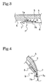
- Fig. 3 schematically shows the arrangement relationship of the sheet piece 7 in a cross section seen in the direction of the arrows A-A in Part (a) of Fig. 2 .
- the sheet piece 7 is disposed to traverse the adhesive seal part P of the cover rubber layer 6 as shown in the figures.
- the decomposition gas G generated from the tacky sealant layer 5 is discharged in the direction of the arrow, along a surface 7a on the tacky sealant layer 5 side and a surface 7b on the cover rubber layer 6 side, of the sheet piece 7.
- the decomposition gas G is smoothly discharged.
- the following problem may occur depending on the amount of the decomposition gas G generated from the tacky sealant layer 5 or the viscosity of the tacky sealant layer 5.
- the material of the tacky sealant layer 5 may sometimes flow into a space between the cover rubber layer 6 and the surface 7b to obstruct the discharge of the decomposition gas G. Accordingly, it is preferable that the surface 7a, on the tacky sealant layer 5 side, of the sheet piece 7 be made to be the release face that can be separated from the tacky sealant layer 5.
- Fig. 4 schematically shows the arrangement relationship of the sheet piece 7 in a cross section seen in the direction of the arrows B-B in Fig. 2(b) .
- the sheet piece 7 is disposed to traverse a part of the adhesive seal part Q of the cover rubber layer 6 as shown in the figures.
- the decomposition gas G generated from the tacky sealant layer 5 is discharged in the direction of the arrow, along the surface 7a on the tacky sealant layer 5 side and the surface 7b on the cover rubber layer 6 side, of the sheet piece 7.
- the decomposition gas G is smoothly discharged.
- the following problem may occur depending on the amount of the decomposition gas G generated from the tacky sealant layer 5 or the viscosity of the tacky sealant layer 5.
- the material of the tacky sealant layer 5 may sometimes flow into a space between the cover rubber layer 6 and the surface 7b to obstruct the discharge of the decomposition gas G. Accordingly, it is preferable that the surface 7a, on the tacky sealant layer 5 side, of the sheet piece 7 be made to be the release face that can be separated from the tacky sealant layer 5.
- Disposing the sheet piece 7 as described above allows the decomposition gas G generated from the tacky sealant layer 5 at the curing process to be discharged from the inside of the tire immediately after the curing process to the tire inner surface side along the release face of the sheet piece 7. Accordingly, it is possible to promptly discharge the decomposition gas G without causing expansion and deformation of the cover rubber layer 6, and to thus suppress the non-uniform flow of the sealant of the tacky sealant layer 5. As a result, the uniformity of the tire is not deteriorated. Moreover, since uneven distribution of the tacky sealant layer 5 is eliminated, it is possible to secure an excellent sealing effect when the tire is punctured.
- the decomposition gas G generated from the tacky sealant layer 5 is automatically discharged from the tire immediately after the curing process. It should be noted that, however, the decomposition gas G is sometimes difficult to be discharged due to a decrease in the gas pressure associated with a decrease in the amount of the residual gas G. For this reason, the following methods may be employed in order to accelerate the discharge of the residual gas G. Specifically, it is possible to promptly discharge the residual gas G by reducing the pressure on the tire inner surface side, by sucking the gas at the vicinity of the sheet piece 7, or by pressing the cover rubber layer 6 from the tire inner surface side.
- the following problem may occur depending on the amount of the gas G generated from the tacky sealant layer 5 or the viscosity of the tacky sealant layer 5.
- the material of the tacky sealant layer 5 may flow into a space between the cover rubber layer 6 and the surface 7b, on the tacky sealant layer 5 side, of the sheet piece 7, in association with the discharge of the gas G.
- the discharge of the gas G may be prevented.
- the surface 7a, on the tacky sealant layer 5 side, of the sheet piece 7 be made to be a release face that can be separated from the tacky sealant layer 5.
- the width of the sheet constituting the sheet piece 7 may be set within a range approximately from 8 mm to 15 mm in order to smoothly discharge the gas G.
- the material constituting the sheet piece 7 is preferably a rubber, a resin, or a composition of the rubber and the resin.
- the shape of the sheet piece 7 may be any of a single-layer sheet and a laminated sheet, while at least one face of the sheet piece 7 may be formed of a removable material.
- a removable material a silicone resin or a fluororesin may be used.
- the sheet piece 7 may be prepared in the following manner.
- a resin material other than such a removable material as a silicone resin and a fluororesin is used.
- a surface treatment using a release agent or the like is applied to at least one face of the resin material.
- a release agent preferably used is a silicone release agent or a fluorine release agent.
- Part (a) of Fig. 5 is a schematic view in a cross section seen in the direction of the arrows C-C in Part (b) of Fig. 2 , and shows a case where a sheet piece 7 according to another embodiment of the present invention is disposed at a position in the S portion in Part (b) of Fig. 2 .
- the sheet piece 7 is folded, so that part of the release face of the sheet piece 7 faces another part of the release face.
- the sheet piece 7 is arranged, so that the folded surface 7b communicates to both of the inner and outer sides of the adhesive seal part Q, and also that the surface, on the side to which the sheet piece 7 is folded, of the sheet piece 7 faces the cover rubber layer 6.
- Part (a) of Fig. 6 is a perspective view showing another form of a sheet piece 7, according to still another embodiment, used in the present invention.
- the sheet piece 7 is folded on one end side in the longitudinal direction thereof in the same manner as that of the sheet piece 7 shown in Part (a) of Fig. 5 .
- the sheet piece 7 of this embodiment has cuts X each formed in a part of the sheet piece 7 as shown in Part (b) of Fig. 6 .
- a portion, corresponding to each cut X, of the sheet piece 7 is folded to an opposite side along the dashed line in the figure, so that the sheet piece 7 is formed in a T shape as shown in Part (a) of Fig. 6 .
- the sheet piece 7 is arranged, so that the folded part of the sheet piece 7 communicates to the inner and outer sides of the adhesive seal part Q, as shown in the T portion in Part (b) of Fig. 2 .
- the same effects as those of the embodiment shown in Fig. 5 can be achieved in this case as well.
- Fig. 7 shows a yet another embodiment of a sheet piece 7 used in the present invention.
- Fig. 7 is a schematic view corresponding to Part (a) of Fig. 5 , and showing a case where the sheet piece 7 is disposed to traverse a part of the adhesive seal part Q of the cover rubber layer 6 in Part (b) of Fig. 2 .
- the sheet piece 7 is disposed by laminating plural layers (three layers in the figure).
- the laminated sheets may be formed to have different widths.
- all the surfaces of these sheets may be formed to be release faces except an upper surface 7a of the sheet positioned closest to the tacky sealant layer 5. This configuration makes it possible to more smoothly and more promptly discharge the decomposition gas G.
- the rubber component to be decomposed by the peroxide for the tacky sealant layer 5 in the pneumatic tire of the present invention used is, for example, polyisobutylene rubber, isobutylene isoprene rubber (IIR), or isoprene rubber. Note that, it is possible to combine, in addition to the peroxide-decomposable rubber component, another rubber component with the rubber composition forming the tacky sealant layer 5 for the purpose of adjusting the viscosity. As this rubber component, it is possible to use, for example, styrene butadiene rubber, butadiene rubber, or natural rubber.
- peroxide used is, for example, acyl peroxides (for example, benzoyl peroxide, p-chlorobenzoyl peroxide), ketone peroxides (for example, methyl ethyl ketone peroxide), peroxyesters (for example, t-butyl peroxyacetate, t-butyl peroxybenzoate, t-butyl peroxyphthalate), alkyl peroxides (for example, dicumyl peroxide, di-t-butyl peroxybenzoate, 1,3-bis(t-butyl peroxyisopropyl)benzen), hydroperoxides (for example, t-butyl hydroperoxide).
- acyl peroxides for example, benzoyl peroxide, p-chlorobenzoyl peroxide
- ketone peroxides for example, methyl ethyl ketone peroxide
- peroxyesters for example, t-buty
- a catalyst such as cobalt naphthenate may be sometimes added to the rubber composition forming the above-described tacky sealant layer 5 as necessarily for the purpose of accelerating the decomposing of the rubber component with the peroxide.
- an inorganic filler such as carbon black and silica; an adhesive agent such as polybutene; or a plasticizer such as aromatic process oil, naphthenic process oil, and paraffinic process oil is added to the rubber composition in some cases.
- the pneumatic tire of the present invention has the following configuration.
- the tacky sealant layer formed of the rubber component decomposable by the peroxide is disposed on the inner side of the tread part. Then, the inner side of the tacky sealant layer is covered with the cover rubber layer.
- the sheet piece having a removable surface, which can be separated is disposed to traverse the seal part. The sheet piece also protrudes, at one end thereof, to the tire inner surface side.
- the present invention may be applied widely to pneumatic tires provided with a tacky sealant layer formed of a rubber component decomposable by a peroxide.
Landscapes
- Engineering & Computer Science (AREA)
- Mechanical Engineering (AREA)
- Tires In General (AREA)
Abstract
This invention provides a pneumatic tire (T) including: a tacky sealant layer (5) formed of a rubber component decomposable by a peroxide, and disposed on the inner side of an inner liner (4) in a region corresponding to a tread part (1); and a cover rubber layer (6) covering the inner side of the tacky sealant layer (5). A sheet piece (7) is disposed to traverse an adhesive seal part (Q) and/or (P) at an edge portion of the cover rubber layer (6), while at least one surface of the sheet piece (7) is a release face which can be separated from at least one of the tacky sealant layer (5) and the cover rubber layer (6). A first end of the sheet piece (7) is inserted between the tacky sealant layer (5) and the cover rubber layer (6) while a second end thereof protrudes to the outer side of the adhesive seal part (Q) and/or (P). According to this configuration, since a decomposition gas generated from the tacky sealant layer at the time of curing is smoothly discharged, it is possible to prevent the uniformity from being deteriorated.
Description
- The present invention relates to a pneumatic tire. Specifically, the present invention relates to a pneumatic tire in which a tacky sealant layer formed of a rubber component decomposable by a peroxide is disposed on the inner side of the tread portion, the pneumatic tire being capable of preventing deterioration in its uniformity by smoothly removing a decomposition gas generated at the time of curing.
- In order to secure the safety driving of a vehicle when the tire runs over a nail or the like during the traveling, a rapid reduction in the air pressure due to the puncture has to be avoided. For this purpose, a large number of pneumatic tires have been proposed, in which a tacky sealant layer is disposed on the inner side of the tread portion.
- For such a tacky sealant layer, there has been a technique using the characteristic of polyisobutylene rubber that is decomposable by a peroxide (see, for example, Patent Document 1). In this technique, a rubber composition containing polyisobutylene rubber, an inorganic filler, and a peroxide is firstly disposed on the inner side of the tread portion of a green tire. Then, the rubber component in the rubber composition is decomposed by utilizing heat generated at the time of curing the green tire, so that the rubber composition is modified into a tacky sealant layer having viscous fluidity.
- However, troubles may occur due to a tacky sealant layer obtained by decomposing the rubber component by the peroxide as described above. In a state where the tacky sealant layer is exposed to the outside, a deflected flow may occur therein during storage, and also the tacky sealant layer makes it difficult to mount the tire on a rim. For the purpose of avoiding these troubles, the surface of the tacky sealant layer is usually covered with a cover rubber layer. However, when the rubber component is decomposed, a large amount of decomposition gas is generated, thus leading to the following problem. Specifically, the generated decomposition gas is, as shown in
Fig. 8 , filled in a space between thetacky sealant layer 5 and thecover rubber layer 6. If the tire runs in this state, the sealant of thetacky sealant layer 5 flows non-uniformly. As a result, thetacky sealant layer 5 is unevenly distributed, and the uniformity of the tire is eventually deteriorated. In this respect, the following countermeasures to this problem have been proposed. Specifically, a material with excellent gas permeability is used for thecover rubber layer 6. Alternatively, a twisted yarn for allowing the decomposition gas G to be discharged is disposed between thetacky sealant layer 5 and thecover rubber layer 6, and one end of the twisted yarn is extended from the edge portion of the cover rubber layer (see, for example, Patent Document 2). - However, when any of these proposals is employed, it takes a long time for the decomposition gas to be completely discharged. In the meantime, uneven distribution of the tacky sealant layer occurs due to non-uniform flow of the sealant. In addition, since the cover rubber layer is stretched by the gas pressure, wrinkles remain in the cover rubber layer after the decomposition gas is completely discharged. Accordingly, these proposals cannot completely eliminate factors of deteriorating the uniformity, and thus are not adequate countermeasures.
- Patent Document 1: Japanese patent application Kokai publication No.
Sho 53-55802 - Patent Document 2: Japanese patent application Kokai publication No.
2004-322811 - An object of the present invention is to solve the above-described problems associated with the conventional techniques. Specifically, the present invention provides a pneumatic tire capable of smoothly discharging a decomposition gas generated from a tacky sealant layer at the time of curing so as to prevent the uniformity from being deteriorated.
- The present invention for achieving the above-described object provides a pneumatic tire having the following characteristics. In the pneumatic tire, a tacky sealant layer formed of a rubber component decomposable by a peroxide is disposed on the inner side of an inner liner in a region corresponding to a tread part, and also in which the tacky sealant layer is covered with a cover rubber layer. In addition, in the pneumatic tire, a sheet piece is disposed to traverse a part of an adhesion seal part at an edge portion of the cover rubber layer. The sheet piece is inserted, at a first end thereof, between the tacky sealant layer and the cover rubber layer on the inner side of the adhesive seal part, and also protrudes, at a second end thereof, to the outer side of the adhesive seal part. Concurrently, at least one surface of the sheet piece is formed to be a release face which can be separated from at least one of the tacky sealant layer and the cover rubber layer.
- According to the present invention, the sheet piece is disposed in the adhesive seal part at the edge portion of the cover rubber layer covering the tacky sealant layer so as to traverse a part of the adhesive seal part. Concurrently, the sheet piece has at least one surface as the release face that can be separated from at least one of the tacky sealant layer and the cover rubber layer. Accordingly, a decomposition gas generated on the inner side of the cover rubber layer at the time of curing is discharged to the outside via the release face of the sheet piece. This makes it possible to promptly discharge the decomposition gas without causing the cover rubber layer to be expanded and deformed by the gas pressure of the decompression gas. As a result, since non-uniform flow of the tacky sealant layer can be suppressed, the uniformity of the tire is not deteriorated. Moreover, since the uneven distribution of the tacky sealant layer is eliminated, it is possible to secure an excellent sealing effect at the time of puncture.
-
- [
Fig. 1] Fig. 1 is a half sectional view, taken along the meridional direction, and showing an example of a pneumatic tire according to the present invention. - [
Fig. 2 ] Part (a) and (b) ofFigs. 2 are plan views seen from the inner side of the tire, and each showing a part of a cover rubber layer in the tire shown inFig. 1 . - [
Fig. 3] Fig. 3 is a partial sectional view schematically showing the arrangement relationship of a sheet piece in a cross section seen in the direction of the arrows A-A in Part (a) ofFig. 2 . - [
Fig. 4] Fig. 4 is a partial sectional view schematically showing the arrangement relationship of a sheet piece in a cross section in the direction of the arrows B-B in Part (b) ofFig. 2 . - [
Fig. 5 ] Part (a) ofFig. 5 is a partially cross-sectional view schematically showing the arrangement relationship of the sheet piece in a cross section seen in the direction of the arrows C-C inFig. 2(b) , and shows a case where a sheet piece according to another embodiment of the present invention is disposed at a position in the S portion in Part (b) ofFig. 2 . Parts (b) and (c) ofFig. 5 are cross-sectional views each illustrating the shape of a folded sheet piece. - [
Fig. 6 ] Part (a) ofFig. 6 is a perspective view showing a sheet piece according to still another embodiment of the present invention, while Part (b) thereof is a plan view illustrating a process of forming the sheet piece shown in Part (a). - [
Fig. 7] Fig. 7 is a schematic view corresponding to Part (a) ofFig. 5 , and showing a case where a sheet piece according to yet another embodiment of the present invention is disposed. [Fig. 8] Fig. 8 is a cross-sectional view showing an example of a conventional pneumatic tire. - Hereinafter, the configuration of the present invention will be described in detail with reference to the accompanying drawings.
Fig. 1 is a half sectional view showing an example of a pneumatic tire according to an embodiment of the present invention. Parts (a) and (b) ofFigs. 2 are plan views seen from the inner side of the tire, and each showing a part of a cover layer disposed on the inner side of a tread part of the tire shown inFig. 1 . - As seen in
Fig. 1 , a pneumatic tire T includes a tread part 1, a pair of left andright bead parts 2, and sidewall parts 3 each continuously connecting the tread part 1 and a corresponding one of thebead parts 2 to each other. Atacky sealant layer 5 is disposed, on the inner side of aninner liner 4, in a region corresponding to the tread part 1. Thetacky sealant layer 5 is formed of a rubber component decomposable by a peroxide. The inner side of thetacky sealant layer 5 is covered with acover rubber layer 6. - A
sheet piece 7 is disposed at an adhesive seal part Q in an edge portion of thecover rubber layer 6 so as to traverse a part of the adhesive seal part Q. Thesheet piece 7 has at least one face made to be a release face that can be separated from at least one of thetacky sealant layer 5 and thecover rubber layer 6. One end portion of thesheet piece 7 is inserted between thetacky sealant layer 5 and thecover rubber layer 6 on the inner side of the adhesive seal part Q, while the other end thereof protrudes to the outer side of the adhesive seal part Q. - With this
sheet piece 7, a decomposition gas generated on the inner side of thecover rubber layer 6 during curing is discharged to the outside via the release face of thesheet piece 7. This makes it possible to promptly discharge the decomposition gas without causing thecover rubber layer 6 to be expanded and deformed by the gas pressure of the decomposition gas. Accordingly, since a non-uniform flow of the sealant of thetacky sealant layer 5 is suppressed, the uniformity of the tire is not deteriorated. Moreover, since uneven distribution of thetacky sealant layer 5 is eliminated, it is possible to secure an excellent sealing effect when the tire is punctured. -
Fig. 1 shows the case where thesheet piece 7 is disposed to traverse a part of the adhesive seal part Q, which is the joint portion of thecover rubber layer 6 to the inner liner 4 (not illustrated) in the edge portion, in the tire width direction, of thecover rubber layer 6, as indicated by the S or T portion in Part (b) ofFig. 2 . However, the above-describedsheet piece 7 may be disposed, as indicated by the R portion in Part (a) ofFig. 2 , to traverse a part of an adhesive seal part P that is an overlapping joint portion (spliced portion), in the tire circumferential direction T, of the two end portions of thecover rubber layer 6. -
Fig. 3 schematically shows the arrangement relationship of thesheet piece 7 in a cross section seen in the direction of the arrows A-A in Part (a) ofFig. 2 . Suppose the case where thesheet piece 7 is disposed to traverse the adhesive seal part P of thecover rubber layer 6 as shown in the figures. In this case, the decomposition gas G generated from thetacky sealant layer 5 is discharged in the direction of the arrow, along asurface 7a on thetacky sealant layer 5 side and asurface 7b on thecover rubber layer 6 side, of thesheet piece 7. In other words, since at least one of thesurface 7a and thesurface 7b is made to be a release face that can be separated from thetacky sealant layer 5 and thecover rubber layer 6, the decomposition gas G is smoothly discharged. However, the following problem may occur depending on the amount of the decomposition gas G generated from thetacky sealant layer 5 or the viscosity of thetacky sealant layer 5. Specifically, the material of thetacky sealant layer 5 may sometimes flow into a space between thecover rubber layer 6 and thesurface 7b to obstruct the discharge of the decomposition gas G. Accordingly, it is preferable that thesurface 7a, on thetacky sealant layer 5 side, of thesheet piece 7 be made to be the release face that can be separated from thetacky sealant layer 5. -
Fig. 4 schematically shows the arrangement relationship of thesheet piece 7 in a cross section seen in the direction of the arrows B-B inFig. 2(b) . Suppose the case where thesheet piece 7 is disposed to traverse a part of the adhesive seal part Q of thecover rubber layer 6 as shown in the figures. In this case, the decomposition gas G generated from thetacky sealant layer 5 is discharged in the direction of the arrow, along thesurface 7a on thetacky sealant layer 5 side and thesurface 7b on thecover rubber layer 6 side, of thesheet piece 7. Even in this case, since at least one of thesurface 7a and thesurface 7b is made to be a release face that can be separated from thetacky sealant layer 5 and thecover rubber layer 6, the decomposition gas G is smoothly discharged. However, in the same manner as the case ofFig. 3 , the following problem may occur depending on the amount of the decomposition gas G generated from thetacky sealant layer 5 or the viscosity of thetacky sealant layer 5. Specifically, the material of thetacky sealant layer 5 may sometimes flow into a space between thecover rubber layer 6 and thesurface 7b to obstruct the discharge of the decomposition gas G. Accordingly, it is preferable that thesurface 7a, on thetacky sealant layer 5 side, of thesheet piece 7 be made to be the release face that can be separated from thetacky sealant layer 5. - Disposing the
sheet piece 7 as described above allows the decomposition gas G generated from thetacky sealant layer 5 at the curing process to be discharged from the inside of the tire immediately after the curing process to the tire inner surface side along the release face of thesheet piece 7. Accordingly, it is possible to promptly discharge the decomposition gas G without causing expansion and deformation of thecover rubber layer 6, and to thus suppress the non-uniform flow of the sealant of thetacky sealant layer 5. As a result, the uniformity of the tire is not deteriorated. Moreover, since uneven distribution of thetacky sealant layer 5 is eliminated, it is possible to secure an excellent sealing effect when the tire is punctured. - The decomposition gas G generated from the
tacky sealant layer 5 is automatically discharged from the tire immediately after the curing process. It should be noted that, however, the decomposition gas G is sometimes difficult to be discharged due to a decrease in the gas pressure associated with a decrease in the amount of the residual gas G. For this reason, the following methods may be employed in order to accelerate the discharge of the residual gas G. Specifically, it is possible to promptly discharge the residual gas G by reducing the pressure on the tire inner surface side, by sucking the gas at the vicinity of thesheet piece 7, or by pressing thecover rubber layer 6 from the tire inner surface side. - As described above, the following problem may occur depending on the amount of the gas G generated from the
tacky sealant layer 5 or the viscosity of thetacky sealant layer 5. Specifically, the material of thetacky sealant layer 5 may flow into a space between thecover rubber layer 6 and thesurface 7b, on thetacky sealant layer 5 side, of thesheet piece 7, in association with the discharge of the gas G. As a result, the discharge of the gas G may be prevented. For this reason, it is preferable that thesurface 7a, on thetacky sealant layer 5 side, of thesheet piece 7 be made to be a release face that can be separated from thetacky sealant layer 5. Note that, in the present invention, the width of the sheet constituting thesheet piece 7 may be set within a range approximately from 8 mm to 15 mm in order to smoothly discharge the gas G. - In the present invention, although not particularly limited, the material constituting the
sheet piece 7 is preferably a rubber, a resin, or a composition of the rubber and the resin. The shape of thesheet piece 7 may be any of a single-layer sheet and a laminated sheet, while at least one face of thesheet piece 7 may be formed of a removable material. As such a removable material, a silicone resin or a fluororesin may be used. Alternatively, thesheet piece 7 may be prepared in the following manner. As the material constituting thesheet piece 7, a resin material other than such a removable material as a silicone resin and a fluororesin is used. Then, a surface treatment using a release agent or the like is applied to at least one face of the resin material. As such a release agent, preferably used is a silicone release agent or a fluorine release agent. - Part (a) of
Fig. 5 is a schematic view in a cross section seen in the direction of the arrows C-C in Part (b) ofFig. 2 , and shows a case where asheet piece 7 according to another embodiment of the present invention is disposed at a position in the S portion in Part (b) ofFig. 2 . In this embodiment, thesheet piece 7 is folded, so that part of the release face of thesheet piece 7 faces another part of the release face. Then, thesheet piece 7 is arranged, so that the foldedsurface 7b communicates to both of the inner and outer sides of the adhesive seal part Q, and also that the surface, on the side to which thesheet piece 7 is folded, of thesheet piece 7 faces thecover rubber layer 6. This configuration makes it difficult for the sealant of thetacky sealant layer 5 to flow into thesurface 7b side on the inner side of the folded parts. Accordingly, the decomposition gas G generated from thetacky sealant layer 5 is likely to flow through the space on thesurface 7b of the folded parts. It should be noted that, when thesheet piece 7 is folded as described above, the form of the foldedsheet piece 7 may be one illustrated in Part (b) or (c) ofFig. 5 . Part (c) ofFig. 5 illustrates a configuration using two sheet pieces. - Part (a) of
Fig. 6 is a perspective view showing another form of asheet piece 7, according to still another embodiment, used in the present invention. In Part (a) ofFig. 6 , thesheet piece 7 is folded on one end side in the longitudinal direction thereof in the same manner as that of thesheet piece 7 shown in Part (a) ofFig. 5 . Thesheet piece 7 of this embodiment has cuts X each formed in a part of thesheet piece 7 as shown in Part (b) ofFig. 6 . Then, a portion, corresponding to each cut X, of thesheet piece 7 is folded to an opposite side along the dashed line in the figure, so that thesheet piece 7 is formed in a T shape as shown in Part (a) ofFig. 6 . Then thesheet piece 7 is arranged, so that the folded part of thesheet piece 7 communicates to the inner and outer sides of the adhesive seal part Q, as shown in the T portion in Part (b) ofFig. 2 . The same effects as those of the embodiment shown inFig. 5 can be achieved in this case as well. -
Fig. 7 shows a yet another embodiment of asheet piece 7 used in the present invention.Fig. 7 is a schematic view corresponding to Part (a) ofFig. 5 , and showing a case where thesheet piece 7 is disposed to traverse a part of the adhesive seal part Q of thecover rubber layer 6 in Part (b) ofFig. 2 . In this embodiment, thesheet piece 7 is disposed by laminating plural layers (three layers in the figure). In the case of this embodiment, the laminated sheets may be formed to have different widths. Moreover, all the surfaces of these sheets may be formed to be release faces except anupper surface 7a of the sheet positioned closest to thetacky sealant layer 5. This configuration makes it possible to more smoothly and more promptly discharge the decomposition gas G. - As the rubber component to be decomposed by the peroxide for the
tacky sealant layer 5 in the pneumatic tire of the present invention, used is, for example, polyisobutylene rubber, isobutylene isoprene rubber (IIR), or isoprene rubber. Note that, it is possible to combine, in addition to the peroxide-decomposable rubber component, another rubber component with the rubber composition forming thetacky sealant layer 5 for the purpose of adjusting the viscosity. As this rubber component, it is possible to use, for example, styrene butadiene rubber, butadiene rubber, or natural rubber. - Moreover, as the peroxide, used is, for example, acyl peroxides (for example, benzoyl peroxide, p-chlorobenzoyl peroxide), ketone peroxides (for example, methyl ethyl ketone peroxide), peroxyesters (for example, t-butyl peroxyacetate, t-butyl peroxybenzoate, t-butyl peroxyphthalate), alkyl peroxides (for example, dicumyl peroxide, di-t-butyl peroxybenzoate, 1,3-bis(t-butyl peroxyisopropyl)benzen), hydroperoxides (for example, t-butyl hydroperoxide).
- In addition, a catalyst such as cobalt naphthenate may be sometimes added to the rubber composition forming the above-described
tacky sealant layer 5 as necessarily for the purpose of accelerating the decomposing of the rubber component with the peroxide. Moreover, an inorganic filler such as carbon black and silica; an adhesive agent such as polybutene; or a plasticizer such as aromatic process oil, naphthenic process oil, and paraffinic process oil is added to the rubber composition in some cases. - As described above, the pneumatic tire of the present invention has the following configuration. The tacky sealant layer formed of the rubber component decomposable by the peroxide is disposed on the inner side of the tread part. Then, the inner side of the tacky sealant layer is covered with the cover rubber layer. Moreover, in this pneumatic tire, at the adhesive seal part in the edge portion of the cover rubber layer, the sheet piece having a removable surface, which can be separated, is disposed to traverse the seal part. The sheet piece also protrudes, at one end thereof, to the tire inner surface side. This configuration makes it possible to smoothly discharge the decomposition gas without causing expansion and deformation of the cover rubber layer. Accordingly, it is possible to prevent the uniformity of the tire from being deteriorated as well as to secure an excellent sealing effect at the time when the tire is punctured. Since providing excellent effects with its simple configuration, the present invention may be applied widely to pneumatic tires provided with a tacky sealant layer formed of a rubber component decomposable by a peroxide.
Claims (8)
- A pneumatic tire characterized by comprising:a tacky sealant layer formed of a rubber component decomposable by a peroxide, and disposed on the inner side of an inner liner in a region corresponding to a tread part;a cover rubber layer covering the tacky sealant layer; anda sheet piece disposed to traverse a part of an adhesive seal part at a an edge portion of the cover rubber layer,characterized in that one end of the sheet piece is inserted between the tacky sealant layer and the cover rubber layer on the inner side of the adhesive seal part, while the other end thereof protrudes to the outer side of the adhesive seal part, and
that at least one surface of the sheet piece is formed to be a release face which can be separated from at least one of the tacky sealant layer and the cover rubber layer. - The pneumatic tire according to claim 1 characterized in that the adhesive seal part is an overlapping joint portion, in the tire circumferential direction, of the two end portions of the cover rubber layer.
- The pneumatic tire according to claim 1 characterized in that the adhesive seal part is a joint portion of the cover rubber layer to the inner liner in an edge portion, in the tire width direction, of the cover rubber layer.
- The pneumatic tire according to any one of claims 1, 2 and 3 characterized in that the release face is formed of a removable material.
- The pneumatic tire according to claim 4 characterized in that the removable material is any one of a silicone resin and a fluororesin.
- The pneumatic tire according to any one of claims 1, 2 and 3 characterized in that the removable surface is formed of a resin material to which a surface treatment using a release agent is applied.
- The pneumatic tire according to claim 6 characterized in that the release agent is any one of a silicone-based release agent and a fluorine-based release agent.
- The pneumatic tire according to any one of claims 1 to 7,
characterized in that the sheet piece is folded, so that part of the release face of the sheet piece faces another part of the release face, and
that the folded part of the sheet piece communicates to both of the inner side and the outer side of the adhesive seal part.
Applications Claiming Priority (2)
| Application Number | Priority Date | Filing Date | Title |
|---|---|---|---|
| JP2005308475A JP4491564B2 (en) | 2005-10-24 | 2005-10-24 | Pneumatic tire |
| PCT/JP2006/321086 WO2007049570A1 (en) | 2005-10-24 | 2006-10-23 | Pneumatic tire |
Publications (2)
| Publication Number | Publication Date |
|---|---|
| EP1942017A1 true EP1942017A1 (en) | 2008-07-09 |
| EP1942017A4 EP1942017A4 (en) | 2010-01-06 |
Family
ID=37967682
Family Applications (1)
| Application Number | Title | Priority Date | Filing Date |
|---|---|---|---|
| EP06812146A Withdrawn EP1942017A4 (en) | 2005-10-24 | 2006-10-23 | Pneumatic tire |
Country Status (5)
| Country | Link |
|---|---|
| US (1) | US20090266463A1 (en) |
| EP (1) | EP1942017A4 (en) |
| JP (1) | JP4491564B2 (en) |
| CN (1) | CN101296808B (en) |
| WO (1) | WO2007049570A1 (en) |
Cited By (3)
| Publication number | Priority date | Publication date | Assignee | Title |
|---|---|---|---|---|
| EP2042296A1 (en) | 2007-09-28 | 2009-04-01 | The Goodyear Tire & Rubber Company | Pneumatic tire having built-in sealant layer and preparation thereof |
| US8316903B2 (en) | 2007-10-01 | 2012-11-27 | The Goodyear Tire & Rubber Company | Pneumatic tire having built-in sealant layer and preparation thereof |
| US8617333B2 (en) | 2007-09-20 | 2013-12-31 | The Goodyear Tire & Rubber Company | Pneumatic tire having built-in sealant layer and preparation thereof |
Families Citing this family (5)
| Publication number | Priority date | Publication date | Assignee | Title |
|---|---|---|---|---|
| US20090078353A1 (en) * | 2007-09-21 | 2009-03-26 | Ramendra Nath Majumdar | Pneumatic Tire Having Built-In Sealant Layer And Preparation Thereof |
| US8646501B2 (en) | 2010-11-11 | 2014-02-11 | The Goodyear Tire & Rubber Company | Puncture sealant laminate |
| WO2018093962A1 (en) * | 2016-11-17 | 2018-05-24 | Bridgestone Americas Tire Operations, Llc | Pneumatic tire having a sealant layer and air barrier layer |
| CN109130710B (en) * | 2018-08-17 | 2021-01-01 | 安徽佳通乘用子午线轮胎有限公司 | Pneumatic tire with anti-perforation performance and internally attached sealant layer and manufacturing method thereof |
| CN110254136B (en) * | 2019-05-10 | 2023-10-10 | 浙江美亿佳新科技有限公司 | Puncture-proof electric motor car tire and production method thereof |
Family Cites Families (11)
| Publication number | Priority date | Publication date | Assignee | Title |
|---|---|---|---|---|
| JPS5855197B2 (en) | 1976-10-27 | 1983-12-08 | オ−ツタイヤ株式会社 | Pneumatic tire with adhesive sealant composition layer for puncture prevention |
| US4664168A (en) * | 1985-01-22 | 1987-05-12 | The Uniroyal Goodrich Tire Company | Self-sealing tire with edge strips for tire sealant |
| US5085942A (en) * | 1985-01-22 | 1992-02-04 | The Uniroyal Goodrich Tire Company | Sealant product, laminate thereof, and pneumatic tire constructed therewith |
| US4913209A (en) * | 1985-01-22 | 1990-04-03 | The Uniroyal Goodrich Tire Company | Sealant product, laminate thereof, and pneumatic tire constructed therewith |
| WO1995033013A1 (en) * | 1994-05-26 | 1995-12-07 | Minnesota Mining And Manufacturing Company | Extrudable release coating |
| DE69501853T2 (en) * | 1994-06-15 | 1998-10-22 | Agfa Gevaert Nv | Process for the production of a heat-sensitive protected recording material |
| JP2790982B2 (en) * | 1994-11-15 | 1998-08-27 | 住友ゴム工業株式会社 | Pneumatic radial tire |
| DE60225460T2 (en) * | 2001-09-14 | 2009-02-26 | Honda Giken Kogyo K.K. | A pneumatic tire having a sealant layer and method of making the same |
| CA2466763C (en) * | 2002-03-08 | 2011-04-05 | The Yokohama Rubber Co., Ltd. | Self-sealing tire and manufacturing method of the same |
| JP3996796B2 (en) * | 2002-03-25 | 2007-10-24 | 本田技研工業株式会社 | Tubeless tire |
| JP4285603B2 (en) * | 2003-04-24 | 2009-06-24 | 横浜ゴム株式会社 | Pneumatic tire and manufacturing method thereof |
-
2005
- 2005-10-24 JP JP2005308475A patent/JP4491564B2/en not_active Expired - Fee Related
-
2006
- 2006-10-23 WO PCT/JP2006/321086 patent/WO2007049570A1/en not_active Ceased
- 2006-10-23 CN CN2006800395705A patent/CN101296808B/en not_active Expired - Fee Related
- 2006-10-23 US US12/065,544 patent/US20090266463A1/en not_active Abandoned
- 2006-10-23 EP EP06812146A patent/EP1942017A4/en not_active Withdrawn
Non-Patent Citations (2)
| Title |
|---|
| No further relevant documents disclosed * |
| See also references of WO2007049570A1 * |
Cited By (3)
| Publication number | Priority date | Publication date | Assignee | Title |
|---|---|---|---|---|
| US8617333B2 (en) | 2007-09-20 | 2013-12-31 | The Goodyear Tire & Rubber Company | Pneumatic tire having built-in sealant layer and preparation thereof |
| EP2042296A1 (en) | 2007-09-28 | 2009-04-01 | The Goodyear Tire & Rubber Company | Pneumatic tire having built-in sealant layer and preparation thereof |
| US8316903B2 (en) | 2007-10-01 | 2012-11-27 | The Goodyear Tire & Rubber Company | Pneumatic tire having built-in sealant layer and preparation thereof |
Also Published As
| Publication number | Publication date |
|---|---|
| JP2007112378A (en) | 2007-05-10 |
| EP1942017A4 (en) | 2010-01-06 |
| US20090266463A1 (en) | 2009-10-29 |
| CN101296808B (en) | 2010-05-19 |
| CN101296808A (en) | 2008-10-29 |
| WO2007049570A1 (en) | 2007-05-03 |
| JP4491564B2 (en) | 2010-06-30 |
Similar Documents
| Publication | Publication Date | Title |
|---|---|---|
| US20070185269A1 (en) | Rubber composition for puncture-preventive sealant, pneumatic tire having tacky sealant layer, and process for producing the same | |
| US8801884B2 (en) | Method of forming tire innerliner and method of producing pneumatic tire | |
| EP2000292A1 (en) | Method for producing pneumatic tire | |
| JP4167340B2 (en) | Pneumatic tire and method for manufacturing pneumatic tire | |
| EP2082902A1 (en) | Pneumatic tire | |
| US20090266463A1 (en) | Pneumatic tire | |
| JP2003080909A (en) | Pneumatic tire and method of manufacturing the same | |
| JP4559265B2 (en) | Pneumatic tire and manufacturing method thereof | |
| JP3352026B2 (en) | Pneumatic tire and method for manufacturing pneumatic tire | |
| EP1859924B1 (en) | Method for producing pneumatic tire | |
| WO2003033282A1 (en) | Pneumatic tire | |
| US20090205770A1 (en) | Method Of Manufacturing A Pneumatic Tire | |
| JP2003334868A (en) | Manufacturing method of self-sealing tire | |
| US20080156408A1 (en) | Pneumatic Tire and Method of Manufacturing the Same | |
| JP2003159917A (en) | Pneumatic tire and method of manufacturing the same | |
| CN100357090C (en) | Pneumatic tire | |
| JP2004322811A (en) | Pneumatic tire and method of manufacturing the same | |
| US20060174991A1 (en) | Pneumatic tire | |
| JP4255156B2 (en) | Pneumatic tire and method for manufacturing pneumatic tire | |
| JP2007331152A (en) | Tire regeneration method using precured tread | |
| JP2006142925A (en) | Pneumatic tire and its manufacturing method | |
| JP7671139B2 (en) | Pneumatic tire and method of manufacturing same | |
| US10377102B2 (en) | Removable connector for pre-cured tread and methods for forming a retreaded tire |
Legal Events
| Date | Code | Title | Description |
|---|---|---|---|
| PUAI | Public reference made under article 153(3) epc to a published international application that has entered the european phase |
Free format text: ORIGINAL CODE: 0009012 |
|
| 17P | Request for examination filed |
Effective date: 20080310 |
|
| AK | Designated contracting states |
Kind code of ref document: A1 Designated state(s): DE FR |
|
| DAX | Request for extension of the european patent (deleted) | ||
| RBV | Designated contracting states (corrected) |
Designated state(s): DE FR |
|
| A4 | Supplementary search report drawn up and despatched |
Effective date: 20091203 |
|
| 17Q | First examination report despatched |
Effective date: 20100319 |
|
| GRAP | Despatch of communication of intention to grant a patent |
Free format text: ORIGINAL CODE: EPIDOSNIGR1 |
|
| STAA | Information on the status of an ep patent application or granted ep patent |
Free format text: STATUS: THE APPLICATION IS DEEMED TO BE WITHDRAWN |
|
| 18D | Application deemed to be withdrawn |
Effective date: 20120403 |