EP1940153A2 - Image display apparatus, image signal processing apparatus, and image signal processing method - Google Patents
Image display apparatus, image signal processing apparatus, and image signal processing method Download PDFInfo
- Publication number
- EP1940153A2 EP1940153A2 EP07013262A EP07013262A EP1940153A2 EP 1940153 A2 EP1940153 A2 EP 1940153A2 EP 07013262 A EP07013262 A EP 07013262A EP 07013262 A EP07013262 A EP 07013262A EP 1940153 A2 EP1940153 A2 EP 1940153A2
- Authority
- EP
- European Patent Office
- Prior art keywords
- signals
- resolution enhancement
- image
- interlace
- signal processing
- Prior art date
- Legal status (The legal status is an assumption and is not a legal conclusion. Google has not performed a legal analysis and makes no representation as to the accuracy of the status listed.)
- Withdrawn
Links
Images


Classifications
-
- H—ELECTRICITY
- H04—ELECTRIC COMMUNICATION TECHNIQUE
- H04N—PICTORIAL COMMUNICATION, e.g. TELEVISION
- H04N7/00—Television systems
- H04N7/01—Conversion of standards, e.g. involving analogue television standards or digital television standards processed at pixel level
- H04N7/0117—Conversion of standards, e.g. involving analogue television standards or digital television standards processed at pixel level involving conversion of the spatial resolution of the incoming video signal
- H04N7/012—Conversion between an interlaced and a progressive signal
Definitions
- An aspect of the present invention relates to an image display apparatus, an image signal processing apparatus, and an image signal processing method.
- JP-A-2005-20761 discloses an image signal processing apparatus that carries out a resolution enhancement process of inputted image signals (super resolution image processing).
- an image signal processing apparatus including an interlace-to-progressive conversion circuit and a resolution enhancement circuit.
- the interlace-to-progressive conversion circuit outputs first signals by performing an interlace-to-progressive conversion process on image signals.
- the resolution enhancement circuit outputs second signals by performing a resolution enhancement process on the first signals.
- the resolution enhancement circuit performs the resolution enhancement process not on the first signals on which an interpolation process for dynamic images have been performed.
- the interlace-to-progressive conversion circuit may determine whether the image signals are still images or the dynamic images by detecting movements of the image signals, perform a first interpolation process that is the interpolation process for the dynamic images when the image signals are determined to be the dynamic images, perform a second interpolation process that is an interpolation process for the still images when the image signals are determined to be the still images, and output movement detection signals that indicates a result of a determination of the still images or the dynamic images.
- the resolution enhancement circuit may determine whether or not the interpolation process for dynamic images have been performed on the first signals based on the movement detection signals.
- the resolution enhancement circuit may perform the resolution enhancement process by using (1) the image signals and (2) the first signals on which an interpolation process for sill images have been performed.
- the resolution enhancement circuit may perform the resolution enhancement process on the first signals on which an interpolation process for still images have been performed.
- the resolution enhancement circuit may include a sub-pixel shift retrieval portion that obtains a sub-pixel shift from an autocorrelation detected from the first signals and outputs a self-coalesce corresponding point, by performing a sub-pixel shift process.
- the sub-pixel shift retrieval portion may perform the sub-pixel shift process not on the first signals on which the interpolation process for dynamic images have been performed.
- the sub-pixel shift retrieval portion may perform the sub-pixel shift process by using (1) the image signals and (2) the first signals on which an interpolation process for sill images have been performed.
- the sub-pixel shift retrieval portion may perform the sub-pixel shift process on the first signals on which an interpolation process for still images have been performed.
- an image display apparatus including an interlace-to-progressive conversion circuit, a resolution enhancement circuit and a display unit.
- the interlace-to-progressive conversion circuit outputs first signals by performing an interlace-to-progressive conversion process on image signals.
- the resolution enhancement circuit outputs second signals by performing a resolution enhancement process on the first signals.
- the display unit displays images based on the second signals.
- the resolution enhancement circuit performs the resolution enhancement process not on the first signals on which an interpolation process for dynamic images have been performed.
- an image signal processing method for processing image signals including outputting first signals by performing an interlace-to-progressive conversion process on the image signals, and outputting second signals by performing a resolution enhancement process on the first signals, wherein the resolution enhancement process is performed not on the first signals on which an interpolation process for dynamic images have been performed.
- an image display apparatus an image signal processing apparatus, and an image signal processing method, which are capable of obtaining high-quality and highly resolved images.
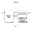
- FIG. 1 is an exemplary block diagram showing a configuration of an image signal processing apparatus according to an embodiment of the present invention
- FIG. 2 is an exemplary block diagram describing a configuration of the first resolution enhancement circuit
- FIG. 3 is an exemplary block diagram showing a television set equipped with an image signal processing apparatus according to an embodiment of the present invention.
- an image signal processing apparatus including an interlace-to-progressive conversion circuit and a resolution enhancement circuit.
- the interlace-to-progressive conversion circuit outputs first signals by performing an interlace-to-progressive conversion process on image signals.
- the resolution enhancement circuit outputs second signals by performing a resolution enhancement process on the first signals.
- the resolution enhancement circuit performs the resolution enhancement process not on the first signals on which an interpolation process for dynamic images have been performed.
- FIG. 1 is an exemplary block diagram showing the structure of the image signal processing apparatus 1 according to the present embodiment.
- the image signal processing apparatus 1 is provided with an interlace-to-progressive conversion circuit 3 and a resolution enhancement circuit 5.
- the interlace-to-progressive conversion circuit 3 carries out an interlace-to-progressive conversion process. That is, the circuit 3 determines dynamic images and still images by detecting movements of images in inputted images (Brightness signal (Y signal) and color difference signal (C signal)), wherein, when still images are determined, an interpolation process for still images is carried out, and when dynamic images are determined, an interpolation process for dynamic images is carried out.
- the interlace-to-progressive conversion circuit 3 outputs image signals (Y signals and C signal), in which an interlace-to-progressive conversion process has been carried out, to the resolution enhancement circuit 5.
- the image signals (Y signals and C signals) outputted from the interlace-to-progressive conversion circuit 3 are image signals (Y signals and C signals) of low resolution.
- the image signals outputted from the interlace-to-progressive conversion circuit 3 are determined to be still images
- the image signals include original image signals inputted into the interlace-to-progressive conversion circuit 3 and image signals in which an interpolation process for still images has been carried out.
- Image signals of different fields in the original image signals inputted in the interlace-to-progressive conversion circuit 3 are employed for the image signals in which an interpolation process for still images has been carried out.
- the image signals outputted from the interlace-to-progressive conversion circuit 3 include original image signals inputted into the interlace-to-progressive conversion circuit 3 and image signals in which an interpolation process for dynamic images has been carried out.
- the image signals in which an interpolation process for dynamic signals are obtained by calculations from image signals between fields in the original image signals are inputted into the interlace-to-progressive conversion circuit 3.
- the interlace-to-progressive conversion circuit 3 outputs the above-described results of determination for dynamic images and still images as movement detection signals.
- the movement detection signals outputted from the interlace-to-progressive conversion circuit 3 are inputted into the resolution enhancement circuit 5.
- the resolution enhancement circuit 5 performs the resolution enhancement process on the image signals (Y signals and C signals) inputted from the interlace-to-progressive conversion circuit 3, and outputs the image signals (Y signals and C signals) that were subjected to the resolution enhancement process.
- the image signals (Y signals and C signals) outputted from the resolution enhancement circuit 5 are image signals (Y signals and C signals) of high resolution.
- the resolution enhancement circuit 5 includes a first resolution enhancement circuit 10 for processing Y signals of low resolution to high resolution, and a second resolution enhancement circuit 20 for processing C signals of low resolution to high resolution.
- FIG. 2 is an exemplary block diagram describing a configuration of the first resolution enhancement circuit 10.
- the first resolution enhancement circuit 10 is provided, as shown in FIG. 2 , with an expansion filter portion 11, a sub-pixel shift retrieval portion 12, corresponding point calculation portions 13 and 16, error calculation portions 14 and 17, and provisional resolution image correction portions 15 and 18.
- the expansion filter portion 11 expands image signals, which are inputted from the interlace-to-progressive conversion circuit 3, by a scaling filter process. Accordingly, image signals (Y signals) of low resolution will be converted to image signals (Y signals) that are provisionally highly resolved.
- the expansion filter portion 11 outputs the provisionally highly resolved image signals (image signals of provisional high resolution) to the corresponding point calculation portion 13 and the provisional resolution image correction portion 15.
- the sub-pixel shift retrieval portion 12 first detects autocorrelation of images in those of low resolution based on the image signals (Y signals) inputted from the interlace-to-progressive conversion circuit 3. And, the sub-pixel shift retrieval portion 12 obtains a sub-pixel shift from the detection result of autocorrelation of the images in those of low resolution, and outputs a self-coalesce corresponding point. The sub-pixel shift retrieval portion 12 outputs the self-coalesce corresponding point to the corresponding point calculation portion 13 and the error calculation portion 14.
- the sub-pixel shift retrieval portion 12 selects original image signals for sub-pixel shift based on the movement detection signals outputted from the interlace-to-progressive conversion circuit 3. That is, the sub-pixel shift retrieval portion 12 determines, based on the movement detection signal inputted from the interlace-to-progressive conversion circuit 3, whether the image signals inputted from the interlace-to-progressive conversion circuit 3 include image signals in which an interpolation process for dynamic images has been carried out.
- the sub-pixel shift retrieval portion 12 does not use the image signals, in which an interpolation process for dynamic images has been carried out, as original image signals for sub-pixel shift when the image signals inputted from the interlace-to-progressive conversion circuit 3 include the image signals in which an interpolation process for dynamic images has been carried out.
- the sub-pixel shift retrieval portion 12 uses the image signals inputted from the interlace-to-progressive conversion circuit 3, that is, the image signals (original image signals for an interlace-to-progressive conversion process) inputted into the interlace-to-progressive conversion circuit 3 and the image signals, in which an interpolation process for still images has been carried out, as the original image signals for sub-pixel shift.
- the sub-pixel shift retrieval portion 12 uses image signals inputted from the interlace-to-progressive conversion circuit 3, that is, image signals inputted into the interlace-to-progressive conversion circuit 3 and image signals, in which an interpolation process for still images has been carried out, as original image signals for a resolution enhancement process.
- Outputs from the expansion filter portion 11 and the sub-pixel shift retrieval portion 12 are inputted into the corresponding point calculation portion 13.
- the corresponding point calculation portion 13 calculates, by a weighting addition computation, the point corresponding to the self-coalesce corresponding point from provisional high resolution images based on the image signals (Provisional high resolution image signals) inputted from the expansion filter portion 11.
- the corresponding point calculation portion 13 outputs the result of calculation (point corresponding to the self-coalesce corresponding point) to the error calculation portion 14.
- Outputs from the corresponding point calculation portion 13 and the sub-pixel shift retrieval portion 12 are inputted into the error calculation portion 14.
- the error calculation portion 14 calculates an error between the point corresponding to the self-coalesce corresponding point, which is outputted from the corresponding point calculation portion 13, and the self-coalesce corresponding point outputted from the sub-pixel shift retrieval portion 12.
- the error calculation portion 14 outputs the result (the above-described error) of calculation to the provisional resolution image correction portion 15.
- the provisional resolution image correction portion 15 corrects the images signals (Provisional high resolution image signals) inputted from the expansion filter portion 11 based on the above-described error calculated by the error calculation portion 14.
- the provisional resolution image correction portion 15 outputs the corrected image signals (Provisional high resolution image signals) to the corresponding point calculation portion 13 and the provisional resolution image correction portion 15.
- the corresponding point calculation portion 16 calculates, by a weighting addition computation, the point corresponding to the self-coalesce corresponding point from provisional high resolution images based on the image signals (Provisional high resolution image signals) inputted from the provisional resolution image correction portion 15.
- the corresponding point calculation portion 16 outputs the result (the point corresponding to the self-coalesce corresponding point) to the error calculation portion 17.
- the error calculation portion 17 calculates an error between the point corresponding to the self-coalesce corresponding point outputted from the corresponding point calculation portion 16 and the self-coalesce corresponding point outputted from the sub-pixel shift retrieval portion 12.
- the error calculation portion 17 outputs the result (the above-described error) of calculation to the provisional resolution image correction portion 18.
- the provisional resolution image correction portion 18 corrects the image signals (Provisional high resolution image signals) inputted from the provisional resolution image correction portion 15 based on the above-described error calculated by the error calculation portion 17.
- the first resolution enhancement circuit 10 repeats a series of processes of the corresponding point calculation, error calculation and correction of provisional high resolution images several times (two times in the present embodiment), and obtains image signals (Y signals) of sharpened high resolution.
- the first resolution enhancement circuit 10 outputs the high resolution image signals (Y signals) thus obtained.
- the second resolution enhancement circuit 20 converts the image signals (C signals) inputted from the interlace-to-progressive conversion circuit 3 in terms of linear HD (High Definition).
- the second resolution enhancement circuit 20 outputs the image signals (C signals), which were subjected to linear HD conversion, as high resolution image signals (C signals).
- the sub-pixel shift retrieval portion 12 does not use the image signals, in which an interpolation process for dynamic images has been carried out, as original image signals for sub-pixel shift when the image signals inputted from the interlace-to-progressive conversion circuit 3 include image signals in which an interpolation process for dynamic images. That is, the resolution enhancement circuit 5 (the first resolution enhancement circuit 10) does not use the image signals, in which an interpolation process for dynamic images has been carried out, for a resolution enhancement process. Therefore, it will be possible to obtain sharp image signals as high resolution image signals. As a result, with the image signal processing apparatus 1, it is possible to obtain high-quality and high-resolution images.
- FIG. 3 is an exemplary block diagram showing one example of a television set provided with the above-described image signal processing apparatus 1 according to the present embodiment.
- the television set 30 is provided with a tuner 31, to which broadcasting signals are supplied from an antenna element, for outputting audiovisual signals by demodulating the same, and an AV switch (SW) portion 33, to which the audiovisual signals are supplied, for carrying out switching with an external input, and a video signal conversion portion 35 that, when video signals are supplied thereto, carries out a predetermined video signal process, converts the same to Y signals and color difference signals, and outputs the same.
- the television set further includes an audio extraction portion 43 for separating audio signals from audiovisual signals, and an amplification portion 45 for appropriately amplifying the audio signals and supplying the same to the speaker 47.
- Non-interlaced video signals are divided into RGB signals by an RGB processor 39, appropriately amplified by a CRT driver 41 and are displayed in a CRT 42 as a video.
- the invention is not limited to the embodiments without modification.
- the invention can be implemented by modifying composite elements of embodiments without departing from the spirit and scope of the invention.
- the invention can be variously implemented by appropriately combining a plurality of composite elements of the embodiments with one another, which are described in the foregoing description thereof. For example, some of the composite elements can be omitted among all the composite elements of the embodiments.
- the composite elements, each of which is provided in different ones of the embodiments can be appropriately combined with one another.
Landscapes
- Engineering & Computer Science (AREA)
- Computer Graphics (AREA)
- Multimedia (AREA)
- Signal Processing (AREA)
- Television Systems (AREA)
- Controls And Circuits For Display Device (AREA)
Abstract
According to one embodiment, there is provided an image signal processing apparatus includes an interlace-to-progressive conversion circuit and a resolution enhancement circuit. The interlace-to-progressive conversion circuit outputs first signals by performing an interlace-to-progressive conversion process on image signals. The resolution enhancement circuit outputs second signals by performing a resolution enhancement process on the first signals. The resolution enhancement circuit performs the resolution enhancement process not on the first signals on which an interpolation process for dynamic images have been performed.
Description
- This application is based upon and claims the benefit of priority from
Japanese Patent Application No. 2006-348122, filed December 25, 2006 - An aspect of the present invention relates to an image display apparatus, an image signal processing apparatus, and an image signal processing method.
-
JP-A-2005-20761 - However, there is a fear that high quality and highly resolved images processing can not be obtained when carrying out resolution enhancement processing for image signals inputted from an interlace-to-progressive conversion circuit. In the image signals in which an interpolation process for dynamic images has been carried out by the interlace-to-progressive conversion circuit, interpolated signals deteriorate in comparison with the original image signals. Therefore, where the image signals in which an interpolation process for dynamic images has been carried out are used as the original image signals for a resolution enhancement process, it is not possible to obtain sharp image signals due to influence of deteriorated signals.
- According to an aspect of the present invention there is provided an image signal processing apparatus including an interlace-to-progressive conversion circuit and a resolution enhancement circuit. The interlace-to-progressive conversion circuit outputs first signals by performing an interlace-to-progressive conversion process on image signals. The resolution enhancement circuit outputs second signals by performing a resolution enhancement process on the first signals. The resolution enhancement circuit performs the resolution enhancement process not on the first signals on which an interpolation process for dynamic images have been performed.
- The interlace-to-progressive conversion circuit may determine whether the image signals are still images or the dynamic images by detecting movements of the image signals, perform a first interpolation process that is the interpolation process for the dynamic images when the image signals are determined to be the dynamic images, perform a second interpolation process that is an interpolation process for the still images when the image signals are determined to be the still images, and output movement detection signals that indicates a result of a determination of the still images or the dynamic images. The resolution enhancement circuit may determine whether or not the interpolation process for dynamic images have been performed on the first signals based on the movement detection signals.
- The resolution enhancement circuit may perform the resolution enhancement process by using (1) the image signals and (2) the first signals on which an interpolation process for sill images have been performed.
- The resolution enhancement circuit may perform the resolution enhancement process on the first signals on which an interpolation process for still images have been performed.
- The resolution enhancement circuit may include a sub-pixel shift retrieval portion that obtains a sub-pixel shift from an autocorrelation detected from the first signals and outputs a self-coalesce corresponding point, by performing a sub-pixel shift process. The sub-pixel shift retrieval portion may perform the sub-pixel shift process not on the first signals on which the interpolation process for dynamic images have been performed.
- The sub-pixel shift retrieval portion may perform the sub-pixel shift process by using (1) the image signals and (2) the first signals on which an interpolation process for sill images have been performed.
- The sub-pixel shift retrieval portion may perform the sub-pixel shift process on the first signals on which an interpolation process for still images have been performed.
- According to another aspect of the present invention there is provided an image display apparatus including an interlace-to-progressive conversion circuit, a resolution enhancement circuit and a display unit. The interlace-to-progressive conversion circuit outputs first signals by performing an interlace-to-progressive conversion process on image signals. The resolution enhancement circuit outputs second signals by performing a resolution enhancement process on the first signals. The display unit displays images based on the second signals. The resolution enhancement circuit performs the resolution enhancement process not on the first signals on which an interpolation process for dynamic images have been performed.
- According to still another aspect of the present invention there is provided an image signal processing method for processing image signals, the method including outputting first signals by performing an interlace-to-progressive conversion process on the image signals, and outputting second signals by performing a resolution enhancement process on the first signals, wherein the resolution enhancement process is performed not on the first signals on which an interpolation process for dynamic images have been performed.
- According to an aspect of the present invention, there is provided an image display apparatus, an image signal processing apparatus, and an image signal processing method, which are capable of obtaining high-quality and highly resolved images.
- A general architecture that implements the various feature of the invention will now be described with reference to the drawings. The drawings and the associated descriptions are provided to illustrate embodiments of the invention and not to limit the scope of the invention.
-
FIG. 1 is an exemplary block diagram showing a configuration of an image signal processing apparatus according to an embodiment of the present invention; -
FIG. 2 is an exemplary block diagram describing a configuration of the first resolution enhancement circuit; and -
FIG. 3 is an exemplary block diagram showing a television set equipped with an image signal processing apparatus according to an embodiment of the present invention. - Various embodiments according to the invention will be described hereinafter with reference to the accompanying drawings. In general, according to one embodiment of the invention, there is provided According to an aspect of the present invention there is provided an image signal processing apparatus including an interlace-to-progressive conversion circuit and a resolution enhancement circuit. The interlace-to-progressive conversion circuit outputs first signals by performing an interlace-to-progressive conversion process on image signals. The resolution enhancement circuit outputs second signals by performing a resolution enhancement process on the first signals. The resolution enhancement circuit performs the resolution enhancement process not on the first signals on which an interpolation process for dynamic images have been performed.
- Hereinafter, a description is given of a preferred embodiment of the present invention with reference to the accompanying drawings. To facilitate understanding of the description, components that are identical to each other in the respective drawings are given the same reference numerals whenever possible, wherein overlapping description thereof is omitted.
- Referring to
FIG. 1 , a description is given of a structure of an image signal processing apparatus 1 according to the present embodiment.FIG. 1 is an exemplary block diagram showing the structure of the image signal processing apparatus 1 according to the present embodiment. The image signal processing apparatus 1 is provided with an interlace-to-progressive conversion circuit 3 and aresolution enhancement circuit 5. - The interlace-to-
progressive conversion circuit 3 carries out an interlace-to-progressive conversion process. That is, thecircuit 3 determines dynamic images and still images by detecting movements of images in inputted images (Brightness signal (Y signal) and color difference signal (C signal)), wherein, when still images are determined, an interpolation process for still images is carried out, and when dynamic images are determined, an interpolation process for dynamic images is carried out. The interlace-to-progressive conversion circuit 3 outputs image signals (Y signals and C signal), in which an interlace-to-progressive conversion process has been carried out, to theresolution enhancement circuit 5. Herein, the image signals (Y signals and C signals) outputted from the interlace-to-progressive conversion circuit 3 are image signals (Y signals and C signals) of low resolution. - Where the image signals outputted from the interlace-to-
progressive conversion circuit 3 are determined to be still images, the image signals include original image signals inputted into the interlace-to-progressive conversion circuit 3 and image signals in which an interpolation process for still images has been carried out. Image signals of different fields in the original image signals inputted in the interlace-to-progressive conversion circuit 3 are employed for the image signals in which an interpolation process for still images has been carried out. - On the other hand, where determined to be dynamic images, the image signals outputted from the interlace-to-
progressive conversion circuit 3 include original image signals inputted into the interlace-to-progressive conversion circuit 3 and image signals in which an interpolation process for dynamic images has been carried out. The image signals in which an interpolation process for dynamic signals are obtained by calculations from image signals between fields in the original image signals are inputted into the interlace-to-progressive conversion circuit 3. Thus, since the image signals in which an interpolation process for dynamic images has been carried out are obtained by calculations, the image signals deteriorate in comparison with the image signals in which an interpolation process for still images has been carried out, wherein the reliability of signals is low. - The interlace-to-
progressive conversion circuit 3 outputs the above-described results of determination for dynamic images and still images as movement detection signals. The movement detection signals outputted from the interlace-to-progressive conversion circuit 3 are inputted into theresolution enhancement circuit 5. - The
resolution enhancement circuit 5 performs the resolution enhancement process on the image signals (Y signals and C signals) inputted from the interlace-to-progressive conversion circuit 3, and outputs the image signals (Y signals and C signals) that were subjected to the resolution enhancement process. Herein, the image signals (Y signals and C signals) outputted from theresolution enhancement circuit 5 are image signals (Y signals and C signals) of high resolution. - The
resolution enhancement circuit 5 includes a firstresolution enhancement circuit 10 for processing Y signals of low resolution to high resolution, and a secondresolution enhancement circuit 20 for processing C signals of low resolution to high resolution. -
FIG. 2 is an exemplary block diagram describing a configuration of the firstresolution enhancement circuit 10. The firstresolution enhancement circuit 10 is provided, as shown inFIG. 2 , with anexpansion filter portion 11, a sub-pixelshift retrieval portion 12, correspondingpoint calculation portions error calculation portions image correction portions - The
expansion filter portion 11 expands image signals, which are inputted from the interlace-to-progressive conversion circuit 3, by a scaling filter process. Accordingly, image signals (Y signals) of low resolution will be converted to image signals (Y signals) that are provisionally highly resolved. Theexpansion filter portion 11 outputs the provisionally highly resolved image signals (image signals of provisional high resolution) to the correspondingpoint calculation portion 13 and the provisional resolutionimage correction portion 15. - The sub-pixel
shift retrieval portion 12 first detects autocorrelation of images in those of low resolution based on the image signals (Y signals) inputted from the interlace-to-progressive conversion circuit 3. And, the sub-pixelshift retrieval portion 12 obtains a sub-pixel shift from the detection result of autocorrelation of the images in those of low resolution, and outputs a self-coalesce corresponding point. The sub-pixelshift retrieval portion 12 outputs the self-coalesce corresponding point to the correspondingpoint calculation portion 13 and theerror calculation portion 14. - Herein, the sub-pixel
shift retrieval portion 12 selects original image signals for sub-pixel shift based on the movement detection signals outputted from the interlace-to-progressive conversion circuit 3. That is, the sub-pixelshift retrieval portion 12 determines, based on the movement detection signal inputted from the interlace-to-progressive conversion circuit 3, whether the image signals inputted from the interlace-to-progressive conversion circuit 3 include image signals in which an interpolation process for dynamic images has been carried out. - And, the sub-pixel
shift retrieval portion 12 does not use the image signals, in which an interpolation process for dynamic images has been carried out, as original image signals for sub-pixel shift when the image signals inputted from the interlace-to-progressive conversion circuit 3 include the image signals in which an interpolation process for dynamic images has been carried out. At this time, the sub-pixelshift retrieval portion 12 uses the image signals inputted from the interlace-to-progressive conversion circuit 3, that is, the image signals (original image signals for an interlace-to-progressive conversion process) inputted into the interlace-to-progressive conversion circuit 3 and the image signals, in which an interpolation process for still images has been carried out, as the original image signals for sub-pixel shift. - On the other hand, when the image signals inputted from the interlace-to-
progressive conversion circuit 3 includes image signals in which an interpolation process for still images has been carried out, the sub-pixelshift retrieval portion 12 uses image signals inputted from the interlace-to-progressive conversion circuit 3, that is, image signals inputted into the interlace-to-progressive conversion circuit 3 and image signals, in which an interpolation process for still images has been carried out, as original image signals for a resolution enhancement process. - Outputs from the
expansion filter portion 11 and the sub-pixelshift retrieval portion 12 are inputted into the correspondingpoint calculation portion 13. The correspondingpoint calculation portion 13 calculates, by a weighting addition computation, the point corresponding to the self-coalesce corresponding point from provisional high resolution images based on the image signals (Provisional high resolution image signals) inputted from theexpansion filter portion 11. The correspondingpoint calculation portion 13 outputs the result of calculation (point corresponding to the self-coalesce corresponding point) to theerror calculation portion 14. - Outputs from the corresponding
point calculation portion 13 and the sub-pixelshift retrieval portion 12 are inputted into theerror calculation portion 14. Theerror calculation portion 14 calculates an error between the point corresponding to the self-coalesce corresponding point, which is outputted from the correspondingpoint calculation portion 13, and the self-coalesce corresponding point outputted from the sub-pixelshift retrieval portion 12. Theerror calculation portion 14 outputs the result (the above-described error) of calculation to the provisional resolutionimage correction portion 15. - Outputs from the
expansion filter portion 11 and theerror calculation portion 14 are inputted into the provisional resolutionimage correction portion 15. The provisional resolutionimage correction portion 15 corrects the images signals (Provisional high resolution image signals) inputted from theexpansion filter portion 11 based on the above-described error calculated by theerror calculation portion 14. The provisional resolutionimage correction portion 15 outputs the corrected image signals (Provisional high resolution image signals) to the correspondingpoint calculation portion 13 and the provisional resolutionimage correction portion 15. - As in the above-described corresponding
point calculation portion 13, the correspondingpoint calculation portion 16 calculates, by a weighting addition computation, the point corresponding to the self-coalesce corresponding point from provisional high resolution images based on the image signals (Provisional high resolution image signals) inputted from the provisional resolutionimage correction portion 15. The correspondingpoint calculation portion 16 outputs the result (the point corresponding to the self-coalesce corresponding point) to theerror calculation portion 17. - As in the above-described
error calculation portion 14, theerror calculation portion 17 calculates an error between the point corresponding to the self-coalesce corresponding point outputted from the correspondingpoint calculation portion 16 and the self-coalesce corresponding point outputted from the sub-pixelshift retrieval portion 12. Theerror calculation portion 17 outputs the result (the above-described error) of calculation to the provisional resolutionimage correction portion 18. - As in the above-described provisional resolution
image correction portion 15, the provisional resolutionimage correction portion 18 corrects the image signals (Provisional high resolution image signals) inputted from the provisional resolutionimage correction portion 15 based on the above-described error calculated by theerror calculation portion 17. - As described above, the first
resolution enhancement circuit 10 repeats a series of processes of the corresponding point calculation, error calculation and correction of provisional high resolution images several times (two times in the present embodiment), and obtains image signals (Y signals) of sharpened high resolution. The firstresolution enhancement circuit 10 outputs the high resolution image signals (Y signals) thus obtained. - The second
resolution enhancement circuit 20 converts the image signals (C signals) inputted from the interlace-to-progressive conversion circuit 3 in terms of linear HD (High Definition). The secondresolution enhancement circuit 20 outputs the image signals (C signals), which were subjected to linear HD conversion, as high resolution image signals (C signals). - As described above, in the present embodiment, the sub-pixel
shift retrieval portion 12 does not use the image signals, in which an interpolation process for dynamic images has been carried out, as original image signals for sub-pixel shift when the image signals inputted from the interlace-to-progressive conversion circuit 3 include image signals in which an interpolation process for dynamic images. That is, the resolution enhancement circuit 5 (the first resolution enhancement circuit 10) does not use the image signals, in which an interpolation process for dynamic images has been carried out, for a resolution enhancement process. Therefore, it will be possible to obtain sharp image signals as high resolution image signals. As a result, with the image signal processing apparatus 1, it is possible to obtain high-quality and high-resolution images. - Subsequently, referring to
FIG. 3 , a description is given of one example of a television set 30 (image display apparatus) provided with the above-described image signal processing apparatus 1.FIG. 3 is an exemplary block diagram showing one example of a television set provided with the above-described image signal processing apparatus 1 according to the present embodiment. - The
television set 30 is provided with atuner 31, to which broadcasting signals are supplied from an antenna element, for outputting audiovisual signals by demodulating the same, and an AV switch (SW)portion 33, to which the audiovisual signals are supplied, for carrying out switching with an external input, and a videosignal conversion portion 35 that, when video signals are supplied thereto, carries out a predetermined video signal process, converts the same to Y signals and color difference signals, and outputs the same. The television set further includes anaudio extraction portion 43 for separating audio signals from audiovisual signals, and anamplification portion 45 for appropriately amplifying the audio signals and supplying the same to thespeaker 47. - Herein, the above-described image signal processing apparatus 1 is applied to the image
signal processing portion 37 to which video signals are supplied from the videosignal conversion portion 35. Non-interlaced video signals are divided into RGB signals by anRGB processor 39, appropriately amplified by aCRT driver 41 and are displayed in aCRT 42 as a video. - Thus, the invention is not limited to the embodiments without modification. The invention can be implemented by modifying composite elements of embodiments without departing from the spirit and scope of the invention. Additionally, the invention can be variously implemented by appropriately combining a plurality of composite elements of the embodiments with one another, which are described in the foregoing description thereof. For example, some of the composite elements can be omitted among all the composite elements of the embodiments. Additionally, the composite elements, each of which is provided in different ones of the embodiments, can be appropriately combined with one another.
Claims (9)
- An image signal processing apparatus comprising:an interlace-to-progressive conversion circuit that outputs first signals by performing an interlace-to-progressive conversion process on image signals; anda resolution enhancement circuit that outputs second signals by performing a resolution enhancement process on the first signals; whereinthe resolution enhancement circuit performs the resolution enhancement process not on the first signals on which an interpolation process for dynamic images have been performed.
- The image signal processing apparatus according to Claim 1, wherein:the interlace-to-progressive conversion circuit:determines whether the image signals are still images or the dynamic images by detecting movements of the image signals,performs a first interpolation process that is the interpolation process for the dynamic images when the image signals are determined to be the dynamic images,performs a second interpolation process that is an interpolation process for the still images when the image signals are determined to be the still images, andoutputs movement detection signals that indicates a result of a determination of the still images or the dynamic images; andthe resolution enhancement circuit determines whether or not the interpolation process for dynamic images have been performed on the first signals based on the movement detection signals.
- The image signal processing apparatus according to Claim 1, wherein the resolution enhancement circuit performs the resolution enhancement process by using (1) the image signals and (2) the first signals on which an interpolation process for sill images have been performed.
- The image signal processing apparatus according to Claims 1, wherein the resolution enhancement circuit performs the resolution enhancement process on the first signals on which an interpolation process for still images have been performed.
- The image signal processing apparatus according to Claim 1, wherein:the resolution enhancement circuit includes a sub-pixel shift retrieval portion that obtains a sub-pixel shift from an autocorrelation detected from the first signals and outputs a self-coalesce corresponding point, by performing a sub-pixel shift process; andthe sub-pixel shift retrieval portion performs the sub-pixel shift process not on the first signals on which the interpolation process for dynamic images have been performed.
- The image signal processing apparatus according to Claim 5, wherein:the sub-pixel shift retrieval portion performs the sub-pixel shift process by using (1) the image signals and (2) the first signals on which an interpolation process for sill images have been performed.
- The image signal processing apparatus according to Claim 5, wherein the sub-pixel shift retrieval portion performs the sub-pixel shift process on the first signals on which an interpolation process for still images have been performed.
- An image display apparatus comprising:an interlace-to-progressive conversion circuit that outputs first signals by performing an interlace-to-progressive conversion process on image signals;a resolution enhancement circuit that outputs second signals by performing a resolution enhancement process on the first signals; anda display unit that displays images based on the second signals; whereinthe resolution enhancement circuit performs the resolution enhancement process not on the first signals on which an interpolation process for dynamic images have been performed.
- An image signal processing method for processing image signals, the method comprising:outputting first signals by performing an interlace-to-progressive conversion process on the image signals; andoutputting second signals by performing a resolution enhancement process on the first signals; whereinthe resolution enhancement process is performed not on the first signals on which an interpolation process for dynamic images have been performed.
Applications Claiming Priority (1)
| Application Number | Priority Date | Filing Date | Title |
|---|---|---|---|
| JP2006348122A JP4950653B2 (en) | 2006-12-25 | 2006-12-25 | Image display device, image signal processing device, and image signal processing method |
Publications (1)
| Publication Number | Publication Date |
|---|---|
| EP1940153A2 true EP1940153A2 (en) | 2008-07-02 |
Family
ID=39301638
Family Applications (1)
| Application Number | Title | Priority Date | Filing Date |
|---|---|---|---|
| EP07013262A Withdrawn EP1940153A2 (en) | 2006-12-25 | 2007-07-06 | Image display apparatus, image signal processing apparatus, and image signal processing method |
Country Status (4)
| Country | Link |
|---|---|
| US (1) | US8218076B2 (en) |
| EP (1) | EP1940153A2 (en) |
| JP (1) | JP4950653B2 (en) |
| CN (1) | CN101212686A (en) |
Cited By (1)
| Publication number | Priority date | Publication date | Assignee | Title |
|---|---|---|---|---|
| EP2394263A4 (en) * | 2009-02-06 | 2014-12-10 | Semiconductor Energy Lab | METHOD FOR CONTROLLING DISPLAY DEVICE |
Families Citing this family (5)
| Publication number | Priority date | Publication date | Assignee | Title |
|---|---|---|---|---|
| KR20210022147A (en) | 2008-12-19 | 2021-03-02 | 가부시키가이샤 한도오따이 에네루기 켄큐쇼 | Method for driving display device |
| JP5448981B2 (en) | 2009-04-08 | 2014-03-19 | 株式会社半導体エネルギー研究所 | Driving method of liquid crystal display device |
| JP5143164B2 (en) * | 2010-03-10 | 2013-02-13 | 株式会社東芝 | Image processing apparatus and image processing method |
| CN103369338B (en) * | 2013-06-25 | 2016-01-20 | 四川虹视显示技术有限公司 | Based on image processing system and the method for the nearly eye binocular imaging system of FPGA |
| WO2015053352A1 (en) * | 2013-10-10 | 2015-04-16 | シャープ株式会社 | Display device and super-resolution processing method |
Family Cites Families (13)
| Publication number | Priority date | Publication date | Assignee | Title |
|---|---|---|---|---|
| GB2231460B (en) * | 1989-05-04 | 1993-06-30 | Sony Corp | Spatial interpolation of digital video signals |
| JP3953561B2 (en) * | 1996-10-15 | 2007-08-08 | 株式会社日立製作所 | Image signal format conversion signal processing method and circuit |
| JPH10145817A (en) | 1996-11-12 | 1998-05-29 | Hitachi Ltd | Signal processing circuit for IP conversion and format conversion of image signal |
| JP4083265B2 (en) | 1997-10-07 | 2008-04-30 | 株式会社日立製作所 | Method and apparatus for converting image signal system |
| US20020063807A1 (en) * | 1999-04-19 | 2002-05-30 | Neal Margulis | Method for Performing Image Transforms in a Digital Display System |
| JP2000333135A (en) * | 1999-05-24 | 2000-11-30 | Matsushita Electric Ind Co Ltd | Video signal high-resolution and high-resolution device |
| KR100504594B1 (en) | 2003-06-27 | 2005-08-30 | 주식회사 성진씨앤씨 | Method of restoring and reconstructing a super-resolution image from a low-resolution compressed image |
| JP4461937B2 (en) * | 2003-09-30 | 2010-05-12 | セイコーエプソン株式会社 | Generation of high-resolution images based on multiple low-resolution images |
| TWI225622B (en) * | 2003-10-24 | 2004-12-21 | Sunplus Technology Co Ltd | Method for detecting the sub-pixel motion for optic navigation device |
| JP2005217970A (en) | 2004-01-30 | 2005-08-11 | Toshiba Corp | Imaging apparatus and driving method thereof |
| JP3972938B2 (en) | 2005-01-24 | 2007-09-05 | 株式会社日立製作所 | Display device |
| JP2006227442A (en) | 2005-02-18 | 2006-08-31 | Sharp Corp | VIDEO SIGNAL PROCESSING DEVICE AND VIDEO DISPLAY DEVICE EQUIPPED WITH THE DEVICE |
| JP4116649B2 (en) * | 2006-05-22 | 2008-07-09 | 株式会社東芝 | High resolution device and method |
-
2006
- 2006-12-25 JP JP2006348122A patent/JP4950653B2/en not_active Expired - Fee Related
-
2007
- 2007-07-06 EP EP07013262A patent/EP1940153A2/en not_active Withdrawn
- 2007-07-06 US US11/774,140 patent/US8218076B2/en active Active
- 2007-07-24 CN CNA2007101363623A patent/CN101212686A/en active Pending
Cited By (5)
| Publication number | Priority date | Publication date | Assignee | Title |
|---|---|---|---|---|
| EP2394263A4 (en) * | 2009-02-06 | 2014-12-10 | Semiconductor Energy Lab | METHOD FOR CONTROLLING DISPLAY DEVICE |
| US8970638B2 (en) | 2009-02-06 | 2015-03-03 | Semiconductor Energy Laboratory Co., Ltd. | Method for driving display device |
| US9583060B2 (en) | 2009-02-06 | 2017-02-28 | Semiconductor Energy Laboratory Co., Ltd. | Method for driving display device |
| US10943549B2 (en) | 2009-02-06 | 2021-03-09 | Semiconductor Energy Laboratory Co., Ltd. | Method for driving display device |
| US11837180B2 (en) | 2009-02-06 | 2023-12-05 | Semiconductor Energy Laboratory Co., Ltd. | Method for driving display device |
Also Published As
| Publication number | Publication date |
|---|---|
| US8218076B2 (en) | 2012-07-10 |
| JP4950653B2 (en) | 2012-06-13 |
| CN101212686A (en) | 2008-07-02 |
| JP2008160565A (en) | 2008-07-10 |
| US20080151102A1 (en) | 2008-06-26 |
Similar Documents
| Publication | Publication Date | Title |
|---|---|---|
| US8218076B2 (en) | Image display apparatus, image signal processing apparatus, and image signal processing method | |
| US20080159395A1 (en) | Video signal processing circuit, video signal processing apparatus, and video signal processing method | |
| US20080239146A1 (en) | Video signal interpolation apparatus and method thereof | |
| US20080043141A1 (en) | Video signal scaling apparatus | |
| JP2007274067A (en) | Noise removing device, noise removing method, and video signal display device | |
| JP2008252591A (en) | Interpolated frame generating apparatus, interpolated frame generating method, and broadcast receiving apparatus | |
| US20080239145A1 (en) | Image expansion apparatus, video display apparatus and image expansion method | |
| US8098327B2 (en) | Moving image frame rate converting apparatus and moving image frame rate converting method | |
| US7649557B2 (en) | Apparatus for processing a digital image signal and methods for processing a digital image signal | |
| JP2001169199A (en) | Circuit and method for correcting subtitle | |
| US8345156B2 (en) | Progressive scanning conversion apparatus and progressive scanning conversion method | |
| US8243814B2 (en) | Combing artifacts detection apparatus and combing artifacts detection method | |
| US20080159396A1 (en) | Video signal processing circuit, video signal processor, and video signal processing method | |
| JP2007324830A (en) | Frame rate conversion apparatus and frame rate conversion method | |
| JP4343255B1 (en) | Image expansion apparatus and image expansion method | |
| JP2016207040A (en) | Image processing apparatus, image processing method, and in-vehicle apparatus | |
| JP5448983B2 (en) | Resolution conversion apparatus and method, scanning line interpolation apparatus and method, and video display apparatus and method | |
| US7649567B2 (en) | Format conversion apparatus, format conversion method, and image display apparatus and image display method using the format conversion apparatus | |
| US6385250B1 (en) | Image processing apparatus and image processing method | |
| JP2008028507A (en) | Image correction circuit, image correction method, and image display apparatus | |
| US20050157172A1 (en) | Video signal processor | |
| US8368816B2 (en) | Circuit and method for detecting motion pictures | |
| JP2001272964A (en) | Multi-image display device | |
| JP2009141689A (en) | Analog-digital conversion system and SCART compatible system | |
| JP2018124377A (en) | Display device, display system, and display method |
Legal Events
| Date | Code | Title | Description |
|---|---|---|---|
| PUAI | Public reference made under article 153(3) epc to a published international application that has entered the european phase |
Free format text: ORIGINAL CODE: 0009012 |
|
| 17P | Request for examination filed |
Effective date: 20070706 |
|
| AK | Designated contracting states |
Kind code of ref document: A2 Designated state(s): AT BE BG CH CY CZ DE DK EE ES FI FR GB GR HU IE IS IT LI LT LU LV MC MT NL PL PT RO SE SI SK TR |
|
| AX | Request for extension of the european patent |
Extension state: AL BA HR MK RS |
|
| STAA | Information on the status of an ep patent application or granted ep patent |
Free format text: STATUS: THE APPLICATION HAS BEEN WITHDRAWN |
|
| 18W | Application withdrawn |
Effective date: 20090303 |