EP1940141A1 - Device for capturing a picture and method for evaluating picture data - Google Patents
Device for capturing a picture and method for evaluating picture data Download PDFInfo
- Publication number
- EP1940141A1 EP1940141A1 EP08151277A EP08151277A EP1940141A1 EP 1940141 A1 EP1940141 A1 EP 1940141A1 EP 08151277 A EP08151277 A EP 08151277A EP 08151277 A EP08151277 A EP 08151277A EP 1940141 A1 EP1940141 A1 EP 1940141A1
- Authority
- EP
- European Patent Office
- Prior art keywords
- sensor means
- detection area
- image
- detection
- imaging means
- Prior art date
- Legal status (The legal status is an assumption and is not a legal conclusion. Google has not performed a legal analysis and makes no representation as to the accuracy of the status listed.)
- Ceased
Links
Images


Classifications
-
- G—PHYSICS
- G01—MEASURING; TESTING
- G01N—INVESTIGATING OR ANALYSING MATERIALS BY DETERMINING THEIR CHEMICAL OR PHYSICAL PROPERTIES
- G01N21/00—Investigating or analysing materials by the use of optical means, i.e. using sub-millimetre waves, infrared, visible or ultraviolet light
- G01N21/84—Systems specially adapted for particular applications
- G01N21/88—Investigating the presence of flaws or contamination
- G01N21/89—Investigating the presence of flaws or contamination in moving material, e.g. running paper or textiles
- G01N21/892—Investigating the presence of flaws or contamination in moving material, e.g. running paper or textiles characterised by the flaw, defect or object feature examined
- G01N21/898—Irregularities in textured or patterned surfaces, e.g. textiles, wood
-
- H—ELECTRICITY
- H04—ELECTRIC COMMUNICATION TECHNIQUE
- H04N—PICTORIAL COMMUNICATION, e.g. TELEVISION
- H04N23/00—Cameras or camera modules comprising electronic image sensors; Control thereof
-
- G—PHYSICS
- G01—MEASURING; TESTING
- G01N—INVESTIGATING OR ANALYSING MATERIALS BY DETERMINING THEIR CHEMICAL OR PHYSICAL PROPERTIES
- G01N21/00—Investigating or analysing materials by the use of optical means, i.e. using sub-millimetre waves, infrared, visible or ultraviolet light
- G01N21/84—Systems specially adapted for particular applications
- G01N21/88—Investigating the presence of flaws or contamination
- G01N21/89—Investigating the presence of flaws or contamination in moving material, e.g. running paper or textiles
- G01N21/8901—Optical details; Scanning details
-
- G—PHYSICS
- G06—COMPUTING; CALCULATING OR COUNTING
- G06T—IMAGE DATA PROCESSING OR GENERATION, IN GENERAL
- G06T7/00—Image analysis
- G06T7/0002—Inspection of images, e.g. flaw detection
- G06T7/0004—Industrial image inspection
- G06T7/001—Industrial image inspection using an image reference approach
-
- H—ELECTRICITY
- H04—ELECTRIC COMMUNICATION TECHNIQUE
- H04N—PICTORIAL COMMUNICATION, e.g. TELEVISION
- H04N23/00—Cameras or camera modules comprising electronic image sensors; Control thereof
- H04N23/58—Means for changing the camera field of view without moving the camera body, e.g. nutating or panning of optics or image sensors
-
- G—PHYSICS
- G06—COMPUTING; CALCULATING OR COUNTING
- G06T—IMAGE DATA PROCESSING OR GENERATION, IN GENERAL
- G06T2207/00—Indexing scheme for image analysis or image enhancement
- G06T2207/30—Subject of image; Context of image processing
- G06T2207/30108—Industrial image inspection
- G06T2207/30144—Printing quality
Definitions
- This document relates to apparatus for capturing an image and method for evaluating image data.
- Apparatuses for capturing an image and methods for evaluating image data can be used, for example, in installations for producing material webs, for example printed paper webs, film webs or textile webs.
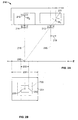
- a detection means 110 can capture an image 100 on a printed material web 101.
- the capture of the image occurs at a sampling time.
- Pictures can be acquired one after the other at different sampling times, for example transversely to web direction A during a transverse movement via a rail system 161 operated by a motor 160.
- the scanning can take place in material web direction A, for example by moving material web 101 in material web direction A.
- the image data can be transmitted via a line 162 to a control and processing unit 163, in which the image data are processed.
- the results may then be determined by means of an output unit 164, such as a Screen to be displayed to the user.
- the display can serve, for example, to assess the print quality of the printed material web 101.
- Via an input unit 165 such as a keyboard, commands can be transmitted to the control and processing unit 163, and thus also to the detection means 110.
- the control and processing unit 163 may also communicate commands to the motor 160.
- An exemplary device includes a variable focal length zoom lens that can detect different areas of an image by moving lens elements in the lens. Zoom lenses can be structurally more complex, cost-intensive and poorer in image quality than fixed fixed focal length lenses.
- Apparatuses for capturing an image and methods for evaluating image data are disclosed.
- an apparatus for capturing an image in an image plane comprises a first sensor means and a first imaging means and at least a second sensor means and at least one second imaging means.
- the device is suitable for detecting a first detection area and at least one second detection area in the image plane.
- the apparatus or method may include one or more of the following features.
- the sensor means and the Imaging means may be arranged such that the second detection area is smaller than the first detection area.
- the sensor means and the imaging means may be arranged such that the second detection area comprises a partial area of the first detection area.
- the sensor means and the imaging means may be arranged such that the second detection area is arranged within the first detection area.
- the first imaging means may comprise a first optical axis and the second imaging means may comprise a second optical axis.
- the first sensor means may be arranged such that a center of the first sensor means has an offset to the first optical axis.
- the first sensor means may be arranged such that a center of the first sensor means is located on a line passing through a center of the first detection area and a center of the first imaging means.
- the second sensor means may be arranged centered to the second optical axis.
- the first sensor means and the first imaging means may be arranged such that the first detection area is imaged by the first imaging means and detected by the first sensor means.
- the second sensor means and the second imaging means may be arranged such that the second detection area is imaged by the second imaging means and detected by the second sensor means.
- the second sensor means may be arranged such that a center of the second sensor means has an offset to the second optical axis.
- the second sensor means may be arranged such that a center of the second sensor means is located on a line passing through a center of the second detection area and a center of the second imaging means.
- the first sensor means may be arranged centered to the first optical axis.
- the first sensor means and the first imaging means may be arranged such that the second detection area is imaged by the first imaging means and detected by the first sensor means.
- the second sensor means and the second imaging means may be arranged such that the first detection area is imaged by the second imaging means and detected by the second sensor means.
- the first optical axis and the second optical axis may be parallel to each other.
- the first sensor means may be arranged in a plane parallel to the image plane.
- the second sensor means may be arranged in a plane parallel to the image plane.
- the first imaging means and the second imaging means may have different focal lengths.
- the first imaging means may have a shorter focal length than the second imaging means.
- the device may be configured such that the second sensor means detects an enlarged image (a smaller image detail) compared to the first sensor means.
- the image can be on a web.
- the first and / or the second imaging means may comprise a lens.
- the first and / or the second imaging means may be a fixed objective.
- the first and / or the second sensor means may be a CMOS chip.
- a method for evaluating image data comprises providing a first detection means and at least one second detection means for capturing an image in an image plane. The method further comprises detecting a first detection area to obtain first image data and detecting at least one second detection area to obtain second image data. Finally, the method comprises evaluating the first and / or the second image data.
- the method or apparatus may include one or more of the following features.
- the evaluation may include calculating image data of a display area from the first and / or the second image data (digital zooming).
- the evaluation may comprise calculating image data continuously in the size of increasing or decreasing display areas from the first and / or second image data (continuous digital zooming).
- the method may include evaluating the second image data if the presentation area is within the second detection area.
- the method may comprise evaluating the first image data if the presentation area is within the first detection area and outside the second detection area.
- the method may further comprise detecting a color reference to obtain color reference data.
- the evaluation may include determining color correction data using the color reference data.
- the evaluation may include color correcting image data using the color correction data.
- Detecting the first or second detection area may include detecting the color reference.
- the color reference may be located in an edge area of the first detection area.
- the first image data may have a first resolution and the second image data may have a second resolution.
- the first resolution may be smaller than the second resolution.
- the first detection means may comprise the first sensor means and the first imaging means.
- the second detection means may comprise the second sensor means and the second imaging means.
- the detection of the first detection area can be performed with the first detection means.
- the detection of the second detection area can be performed with the second detection means.
- the evaluation of the first and / or the second image data can take place in a processing unit.
- the outputting of the display area can be carried out with the aid of an output unit.
- Embodiments may provide any, all, or none of the following advantages.
- the device can detect two differently sized detection areas, for example a zoom area and a wide-angle area, by means of two fixed objectives. Furthermore, two different resolutions can be provided, making it possible to digitally zoom within a large image area to provide a sufficiently high resolution without using a zoom lens. Also, a color correction of image data for any selected display area is possible.
- an apparatus for capturing an image comprises a detection means arranged along a main axis for capturing the image and an illumination means for producing diffuse light.
- the exposure means comprises a light guide means and at least one light source, which is arranged such that its emitted light is coupled into the light guide means and propagates in the light guide means.
- the optical waveguide means is configured such that the light propagating in the optical waveguide means diffusely exits in at least one surface region of the optical waveguide means.
- the device may include one or more of the following features.
- the light guide means may comprise a flat plate. In such a case, the light guide means may be arranged such that the planar plate is arranged in a plane parallel to an object plane, a plane in which the image is located.
- the optical waveguide can be designed such that, with the exception of the surface regions in which the emitted light is coupled in, and the surface regions in which the propagating light emerges diffusely, the surface regions of the optical waveguide means have a mirroring or reflector layer.
- the surface areas on which the emitted light is coupled can be smooth, in particular polished.
- the optical fiber means may be made of a material having scattering particles such that the propagating light diffuses out in the at least one surface region.
- the light guide means may be made of transparent material, in particular acrylic glass.
- the optical fiber means may be configured such that the detecting means detects the image through the optical fiber means.
- the optical fiber means may be configured such that a recess is located in an area in which the detection means detects the image.
- the optical fiber means may be disposed between the detection means and the image.
- the light guide means can also be arranged on the side opposite the detection means side of the image.
- the exposure means may comprise at least two optical fiber means and at least one switching means for selectively blocking or transmitting in one of the optical fiber means propagating light. In such a case, the at least two optical fiber means and the at least one switching means may be arranged alternately to one another.
- the exposure means may be configured such that the at least two lightguide means have a triangular shape.
- the at least two optical fiber means and the at least one switching means may be arranged around a central point forming a closed surface.
- the exposure means may comprise at least a first and a second light source.
- the first and second light sources may be disposed on opposite sides of the light guide means.
- the first and second light sources may be light sources of various types.
- the apparatus may include control means for selectively turning on / off the first or second light source.
- the image may be on a web and the at least one light source may be a gas discharge lamp, in particular a flash tube.
- Embodiments may provide any, all, or none of the following advantages.
- the device can provide a uniform illumination in the detection of an image, whereby also a good image quality can be achieved. Shadowing when capturing the image on a background sheet, such as glossy, highly transparent film webs, can be reliably prevented due to the same detection and exposure direction.
- the device can be realized in a compact design and can have a low installation depth.
- the detection means and the exposure means can form a unit which can be easily used.
- the device can be used in a variety of ways without having to develop an individual and complex lighting concept for each application.
- the device can also be easily provided in various sizes.
- FIG. 2A shows an apparatus 210 for capturing an image in an image plane E.
- the image may be on a printed web, such as a paper or film web, for example. However, the image may also be on pieces of material, such as sheets of paper or blanks.
- the device comprises a first sensor means 211 and a first imaging means 213 as well as a second sensor means 212 and a second imaging means 214.
- the first sensor means 211 and the second sensor means 212 are each arranged in a plane parallel to the image plane E.
- the first imaging means 213 and the second imaging means 214 are located between the image plane E and the first sensor means 211 and the second sensor means 212, respectively.
- the apparatus can detect a first detection area 231 and a second detection area 232 in the image plane E. In FIG. 2A the second detection area 232 (zoom area) is smaller than the first detection area 231 (wide angle area).
- FIG. 2 B shows a plan view of the in FIG. 2A shown capture area in the image plane E (from the perspective of FIG. 2A shown device 210).
- the second detection area 232 comprises a partial area of the first detection area 231 and is arranged within the first 231 detection area.
- the center of the first detection area 231 and the center of the second detection area 232 coincide at a central point 230, that is, the second detection area 232 is located at the center of the first detection area around a central point 230. It should be understood that any other positioning of the second detection area is possible partially or entirely within the first detection area, for example in an edge area of the first detection area.
- the detection of the image in the image plane can be done by using a CMOS chip, such as a CMOS matrix chip, as first and / or second sensor means. It should be understood that detection by any other suitable type of sensor means, such as a CCD chip, is also possible.
- the first imaging means 211 comprises a first optical axis 215, which is shown with a vertical dashed line and which passes through the center of the imaging means 213.
- the second imaging means 212 comprises a second optical axis 216 FIG. 2A
- the first optical axis 215 and the second optical axis 216 are parallel to each other.
- the first and / or second imaging means may be one or more lenses or one or more lenses include.
- An imaging means may for example also be understood as a lens system or a lens.
- the first and second imaging means 213 and 214 shown are each a fixed lens.
- a 20mm lens can be used as the first imaging tool and an 8mm lens as the second imaging tool. It should be understood, however, that the choice of imaging means may be dependent on the particular application.
- the first sensor means 211 is arranged such that the center M1 of the first sensor means 211 has an offset 219 to the first optical axis 215.
- the offset 219 is in FIG. 2A is shown as a distance between the first optical axis 215 passing through the center of the first imaging means 213 and the vertical dashed line passing through the center M1.
- the center M1 of the first sensor means 211 is located on a line which passes through a center 230 of the first detection area 231 and a center of the first imaging means 213. It is thus possible to detect two differently sized detection areas, for example a zoom area and a wide-angle area, by means of two fixed objectives.
- the position and thus the offset of the first sensor means 211 can be calculated by radiation set.
- the size of the offset depends on the particular construction of the device (such as distance to the image plane E). By way of example only, the size of the offset may be less than 1 mm, for example 0.7 mm.
- the first imaging means 213 and the second imaging means 214 have different focal lengths.
- the first imaging means has a focal length B1 and the second imaging means 214 has a focal length B2.
- the first imaging means 213 has a shorter focal length than the second imaging means 214, that is, the focal length B1 is smaller than the focal length B2.
- the first sensor means 211 and the first imaging means 213 with the shorter focal length B1 are arranged such that the first detection area 231, as in FIG FIG. 2A and 2B the wide-angle region represented by the first imaging means 213 and detected by the first sensor means 211 is shown.
- the second sensor means 212 and the second imaging means 214 are arranged such that the second detection area 232, as in FIG FIG.
- the zoom range represented by the second imaging means 214 and detected by the second sensor means 212 is shown.
- the second sensor means 212 detects an enlarged image compared to the first sensor means 211, that is, the second sensor means 212 detects a smaller image detail (zoom) than the first sensor means 211.
- the first sensor means 211 and the second sensor means 212 are respectively in FIG a plane parallel to the image plane E is arranged. As shown, these planes are preferably two different planes.
- the two detection means are arranged in different planes due to the different focal lengths B1 and B2. Depending on the particular construction, however, the two levels can also form the same level.
- the second sensor means 212 may be located centered to the second optical axis 216, as in FIG FIG. 2A and 2B and FIG. 3 shown.
- the center M2 of the second detection means 212 lies on the optical axis 216 of the second detection means.
- the second sensor means may also have an optical axis offset in the same manner as described above with respect to the first detection means.
- the second sensor means is arranged such that the center of the second sensor means has an offset to the second optical axis.
- the second sensor means is then arranged such that the center of the second sensor means is on a line passing through a center of the second detection area and a center of the second imaging means.
- more than one second sensor means and more than a second imaging means may be used to detect more than one second detection range.
- a total of three sensor means and three imaging means may be used to detect each one of three detection areas.
- the third detection area can then be arranged within the second detection area and the second detection area within the first detection area.
- several zoom areas can be realized.
- the first sensor means may be arranged centered to the first optical axis and the second sensor means may have an offset to the second optical axis. Likewise, as described above, both detection means may have an offset to the respective optical axis. Also, the second detection area may be imaged by the first imaging means and detected by the first sensor means and correspondingly the first detection area imaged by the second imaging means and detected by the second sensor means.
- the first detection means comprises the first sensor means 211 and the first imaging means 213.
- the second detection means respectively comprise the second sensor means 212 and the second imaging means 214. Detection of the first detection area 231 is performed with the first detection means and detection of the second detection area 232 becomes performed with the second detection means.
- the second detection area 232 is located in FIG. 2A and 2B within the first detection area 231.
- the second detection means 212 detects an enlarged image (a smaller image area) as compared with the first detection means 211. If the first image data has a first resolution and the second image data has a second resolution, the first resolution is smaller than the second resolution. There are thus provided two different resolutions which can be used in image processing.
- the resolution of the image data may be expressed as the number of pixels relative to a unit of physical length, such as dpi (dots per inch) or ppi (pixels per inch).
- the first and second image data may be stored together in a storage unit.
- evaluating may include calculating image data of a FIG. 2 B illustrated display area 233 of the first and / or the second image data include (digital zooming).
- the selection of the first and / or the second image data can take place in a processing unit, which then for example reads the image data accordingly from the memory unit.
- the selection can be made automatically or by a user. If the selection is automatic, it can be designed as follows.
- the display area 233 is within the second detection area 232 (in FIG FIG. 2 B not shown)
- the second image data is evaluated to calculate image data of the display area 233.
- the display area 233 is within the first detection area 231 and outside of the second detection area 232 (as in FIG FIG.
- the first image data are evaluated to calculate image data of the display area 233.
- the zooming is therefore not optical, such as with a zoom lens, but digitally. By providing two different resolutions, it is possible to digitally zoom within a large image area to provide a sufficiently high resolution without using a zoom lens.
- the evaluation and calculation of image data of the presentation area 233 from the first and / or the second image data can be carried out in a processing unit.
- the image data of the desired display area 233 can be determined by conventional image processing methods. For example, the calculation can be carried out by determining interpolation values between the individual pixel values of the first and / or second image data.
- the desired display area can then be output by means of an output unit, such as a monitor.
- a picture-in-picture function is also possible by displaying a display area determined from the first picture data in a large window on the output unit, and a display area determined from the second picture data in a small window on the output unit, or vice versa.
- the presentation area 233 may be predetermined or freely selected by the user. Also, continuously increasing in size (zoom out) or decreasing (zoom in) display areas 233 may be used and their image data may then be successively calculated from the first and / or the second image data (continuous digital zooming). In the case where the display areas continuously decrease in size, as soon as the display area 233 falls within the second detection area 232, the evaluation of the first low-resolution image data may be switched to the higher-resolution second image data. It is thus possible to continuously zoom digitally within a large image area while providing a sufficiently high resolution without time delay.
- the method may include detecting a color reference, such as a color reference strip, to obtain color reference data (color calibration).
- the detection of the color reference can take place during the detection of the first or the second detection area.
- the color reference may be in an edge region of the in FIG. 2 B shown first detection area 231 are located.
- the color reference may, for example, in the first detection means (see FIG. 2A ) and imaged on an edge area of the first detection area 231.
- color correction data can then be determined with the aid of the color reference data, for example by comparing the color reference data with the image data. If a deviation of the image data from the color reference data is determined, then the image data can be correspondingly color-corrected for any selected display area. With a zoom lens, this would not be possible because, if the color reference is in a border area, not every selected viewport would capture that color reference. By using two detection means comprising fixed lenses, as described above, a color correction can be provided for each selected display area.
- FIG. 4 shows an apparatus 210 for capturing an image in an image plane (not shown) having two imaging means or objectives 213 and 214 and an exposure means 220.
- a first detection area wide angle area
- a second detection area zoom range
- the selection of the first and / or second detection range can be done automatically or by a user via a control unit.
- the image may be exposed by means of the exposure means 220.
- Exposure means 220 shown comprises a light guide means 221 which has a continuous recess 241 in a region in which the first objective 213 and the second objective 214 are arranged. Exposure means will be described in more detail below.
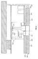
- FIG. 5 shows an apparatus for capturing an image 200 with a detection means 210 and an exposure means 220.
- the image is on an object 201, such as a web of material, in an object plane E.
- the image may be a still image, a video image, or any of the images other appropriate form of a picture.
- the detection means is arranged along a major axis H.
- the detection means may be, for example, a CCD or CMOS camera or any other suitable type of detection means.
- the light source 222 is arranged such that its emitted light is coupled into the light guide means 221 and propagates in the light guide means 221.
- the light propagating in the optical fiber means 221 then diffuses in a surface region 223, or side 223, of the optical fiber means 221 facing the image 200.
- a uniform illumination can be provided in the detection of the image 200, whereby also a good image quality can be achieved.
- Walls 290 having a diffuse white surface which provide a channel between the exposure means 220 and the image 200, are shown.
- the diffused light can be optimally directed to the area to be illuminated and the luminous intensity in this area can be increased.
- a very good reproduction of holograms or reflective surfaces can be ensured.
- the optical fiber means 221 is a flat plate and is centered about the main axis H of the detection means 210.
- the flat plate is located in a plane parallel to an object plane E, which in turn can be achieved a uniform illumination.
- the exposure means is easy and can be produced in a variety of sizes.
- the device can be easily provided in various sizes.
- the light guide means may also be arranged eccentrically about the main axis of the detection means.
- the optical fiber means can also be arranged away from or next to the detection means, as long as this arrangement an optimal illumination corresponding to the application can be achieved.
- the light source 222 is arranged in the vicinity of the surface regions 224, the side 224, of the plate 221.
- a reflector 227 is arranged around the light source 222.
- the reflector 227 reflects the light emitted by the light source 222, which is emitted in the remaining spatial directions and which could not be coupled into the light guide means without the presence of the reflector.
- the reflector 227 may be formed, for example, round, so as to achieve an optimal reflection of the light on the side 224 out. If the reflector 227 has a parabolic shape, the light source 222 may be arranged, for example, near the focal point of the parabola.
- the surface regions 224 in which the emitted light is coupled in may be smooth, in particular polished or surface-treated in any other way.
- the coupled light propagates in the optical fiber means 221 (in FIG FIG. 5 indicated by arrows).
- the propagating light (total) is reflected.
- the light guide means may have a mirroring or reflector layer 228.
- other suitable means of inducing reflection may be used.
- a difference between mirror coating and reflector layer may consist in the amount of light which emerges on the side 223 diffuse.
- a reflector layer diffusely reflects the light in the light guide means 221, more light can diffuse out of the side 223 as compared to a mirror coating.
- a more uniform light distribution can be achieved by multiple reflection in the optical waveguide 221 with a mirror coating.
- a surface area of the optical fiber means may be both a partial area of one side and an entire side of the optical fiber means.
- the optical fiber means 221 of FIG. 5 is thus configured such that the propagating light is totally reflected at all surface areas or sides of the light guide means 221, for example by a mirror or reflector layer 228, 229, with the exception of the surface regions 224, in which the emitted light is coupled in, and the surface regions 223 in which the propagating light emerges diffusely.
- the light guide means 221 may be made of a material with scattering particles.
- the material of the optical fiber means itself may be, for example, a transparent polymer such as PMMA. However, the material may also be glass or the like.
- the scattering particles contained in the material of the optical fiber means may be, for example, organic and / or inorganic.
- the scattering particles have one of the refractive index of the optical fiber material deviating refractive index.
- the intensity of the light scattering depends inter alia on the size of the scattering particles and the difference between the refractive indices of the optical waveguide material and the scattering particles.
- the optical fiber means may also be of other suitable type, such as a special optical film or the like, when it is achieved that the light emerges diffusely.
- the light guide means 221 is arranged between the detection means 210 and the image 200.
- the light guide means 221 may be made of transparent material, in particular glass or acrylic glass.
- the detection means 210 as in FIG FIG. 5 shown capture the image 200 through the optical fiber 221 therethrough.
- the exposure means 220 may be directly attached to the detection means 210 or to a part carrying the detection means 210.
- the detection means 210 and the exposure means 220 can thus form a unit which can be easily used.
- the device can be used in a variety of ways without having to develop an individual and complex lighting concept for each application.
- the optical fiber means may also be configured such that there is a recess in the region in which the detection means 210 detects the image 200 (in FIG FIG. 5 this area is represented by two diagonal, dashed lines).
- this area is represented by two diagonal, dashed lines.
- a recess is located in the reflector layer 228.
- the recess may be continuous, as shown, but may also form only one cavity, as long as it is ensured that the detection means can capture the image.
- a thin reflector layer can also be provided, through which the detection means can detect the image.
- the recess may for example also be located directly in the light guide means. This recess can be located centrally in the optical waveguide means, However, it may also be located at any other suitable position in the optical fiber means.
- the light guide means is completely transparent or semi-transparent in the region in which the detection means detects the image.
- the light guide means 221 may not only be directly connected between the detection means 210 and the image 200 (as in FIG. 5 As already mentioned, it can be located in any position suitable for the respective application.
- an exposure means 220 ' may be disposed on the opposite side of the image 200 from the detection means 210.
- the exposure means 220 ' also comprises a light guide means 221' and a light source 222 ', which is arranged such that its emitted light is coupled into the light guide means 221' and propagated in the light guide means 221 '.
- a reflector 227 ' may be disposed about the light source 222'.
- This arrangement of the side of the image 200 opposite the detection means 210 can be used, for example, in the detection of an image on a transparent material web.
- the exposure means 220 ' may expose the web 201 from one side while the detecting means 210 takes the image from the other side (backside exposure).
- the use of a light background sheet and possible occurrence of shadowing can thus be avoided.
- a uniform illumination is achieved again.
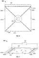
- FIG. 6 shows an exposure means 320 with four optical fiber means 321a-d and four switching means 325a-d.
- the optical fiber means 321a-d and the switching means 325a-d are in FIG. 6 arranged alternately to each other.
- the switching means 325a-d serve to selectively block or pass the light propagating in one of the optical fiber means 321a-d.
- the switching means may be, for example, LCDs or any other suitable type of light switching means.
- the light will coupled by means of a light source 322 on one side of the light guide means 321a.
- the coupled light propagates in the optical fiber means 325a and in the case where, for example, switching means 325d blocks light and switching means 325a transmits light, propagate into the optical fiber means 321b.
- switching means 325b again transmits light, the light can propagate into the switching means 321c and so on.
- selectively only certain areas of space can be illuminated, as may be important for the detection of textiles, for example.
- the lighting can thus be easily adjusted without having to develop an individual and complex lighting concept for each application.
- the four light guide means 321a-d have a triangular shape.
- the four triangular light guide means 321a-d and the four switching means 325a-d are arranged around a central point 340 and form a closed surface. In the region of the central point 340 there may be a recess through which the detection means can detect the image.
- the exposure means may comprise any number of optical fiber means, for example only 2 or even 8 or more optical fiber means.
- two rectangular exposure means may be arranged side by side separated by a switching means, or 8 triangular light guide means, analogous to FIG. 6 to be arranged in an octagon.
- the switching means may be arranged in a plane, but they may also be arranged in several planes forming an angle to one another.
- the in FIG. 6 be shown four light guide means forming a pyramid forming. Any suitable form of arrangement and configuration of the optical fiber means and switching means is possible.
- the illuminance can be selectively selected and be varied.
- the illuminance can be selected to be high enough that the acquisition means can capture the image with sufficiently high image quality only at the time of flashing.
- the function of an iris of the detection means can also be replaced.
- FIG. 7 shows an exposure means 420 with two light sources, a first light source 422a and a second light source 422b.
- the first and second light sources 422a and 422b are disposed on opposite sides 424a and 424b of a light guide means 421. On the sides 424a and 424b, respectively, the emitted light can be coupled into the light guide means 421. The light then propagates in the optical fiber means 421 and exits diffusely on the side 423 of the optical fiber means 421 (in FIG FIG. 7 indicated by arrows).
- the first and second light sources 422a and 422b may be light sources of the same but different types. If they are of different types, for example, one can be a UV light source and the other a white light source. These different light sources can then be used for different applications. In such a case, the device may include control means 450 for selectively turning on / off the first or second light source 422a, 422b.
- Light source may be, for example, a gas discharge lamp, in particular a flash tube, such as a xenon flash tube.
- a flash tube such as a xenon flash tube.
- the use of any suitable type of light source capable of generating a flash of light is possible.
- the flash can be in the range of a few microseconds, such as 1 to 100 microseconds, for example, 10 microseconds.
Abstract
Description
Dieses Dokument bezieht sich auf Vorrichtungen zum Erfassen eines Bildes und Verfahren zum Auswerten von Bilddaten.This document relates to apparatus for capturing an image and method for evaluating image data.
Vorrichtungen zum Erfassen eines Bildes und Verfahren zum Auswerten von Bilddaten können beispielsweise Anwendung finden in Anlagen zur Herstellung von Materialbahnen, wie beispielsweise bedruckte Papierbahnen, Folienbahnen oder Textilbahnen.Apparatuses for capturing an image and methods for evaluating image data can be used, for example, in installations for producing material webs, for example printed paper webs, film webs or textile webs.
Wie in
Bei der Erfassung des Bildes 100 auf der Materialbahn 101 kann es gewünscht sein, einen bestimmten kleineren Bereich innerhalb des größeren erfassten Bereiches zu betrachten, das heißt eine vergrößerte Ansicht des Bildes 100 zu erhalten (Zoomen). Dies kann beispielsweise bei der Beurteilung der Druckqualität einer bedruckten Materialbahn gewünscht sein. Eine beispielhaften Vorrichtung umfasst ein Zoomobjektiv mit variabler Brennweite, welches durch Verschieben von Linsenelementen im Objektiv verschiedene Bereiche eines Bildes erfassen kann. Zoomobjektive können konstruktiv aufwendiger, kostenintensiver und in der Bildqualität schlechter sein als feststehende Objektive mit fester Brennweite.When capturing the
Es werden Vorrichtungen zum Erfassen eines Bildes und Verfahren zum Auswerten von Bilddaten offenbart.Apparatuses for capturing an image and methods for evaluating image data are disclosed.
Nach einem Aspekt umfasst eine Vorrichtung zum Erfassen eines Bildes in einer Bildebene ein erstes Sensormittel und ein erstes Abbildungsmittel sowie mindestens ein zweites Sensormittel und mindestens ein zweites Abbildungsmittel. Die Vorrichtung ist geeignet zum Erfassen eines ersten Erfassungsbereiches und mindestens eines zweiten Erfassungsbereiches in der Bildebene.According to one aspect, an apparatus for capturing an image in an image plane comprises a first sensor means and a first imaging means and at least a second sensor means and at least one second imaging means. The device is suitable for detecting a first detection area and at least one second detection area in the image plane.
In verschiedenen Ausführungsformen kann die Vorrichtung oder das Verfahren eines oder mehrere der folgenden Merkmale aufweisen. Die Sensormittel und die Abbildungsmittel können derart angeordnet sein, dass der zweite Erfassungsbereich kleiner ist als der erste Erfassungsbereich. Die Sensormittel und die Abbildungsmittel können derart angeordnet sein, dass der zweite Erfassungsbereich einen Teilbereich des ersten Erfassungsbereiches umfasst. Die Sensormittel und die Abbildungsmittel können derart angeordnet sein, dass der zweite Erfassungsbereich innerhalb des ersten Erfassungsbereiches angeordnet ist. Das erste Abbildungsmittel kann eine erste optische Achse und das zweite Abbildungsmittel kann eine zweite optische Achse umfassen. Das erste Sensormittel kann derart angeordnet sein, dass ein Mittelpunkt des ersten Sensormittels einen Versatz zu der ersten optischen Achse aufweist. Das erste Sensormittel kann derart angeordnet sein, dass sich ein Mittelpunkt des ersten Sensormittels auf einer Linie befindet, welche durch einen Mittelpunkt des ersten Erfassungsbereiches und einen Mittelpunkt des ersten Abbildungsmittels verläuft. Das zweite Sensormittel kann zentriert zu der zweiten optischen Achse angeordnet sein. Das erste Sensormittel und das erste Abbildungsmittel können derart angeordnet sein, dass der erste Erfassungsbereich durch das erste Abbildungsmittel abgebildet und von dem ersten Sensormittel erfasst wird. Das zweite Sensormittel und das zweite Abbildungsmittel können derart angeordnet sein, dass der zweite Erfassungsbereich durch das zweite Abbildungsmittel abgebildet und von dem zweiten Sensormittel erfasst wird. Das zweite Sensormittel kann derart angeordnet sein, dass ein Mittelpunkt des zweiten Sensormittels einen Versatz zu der zweiten optischen Achse aufweist. Das zweite Sensormittel kann derart angeordnet sein, dass sich ein Mittelpunkt des zweiten Sensormittels auf einer Linie befindet, welche durch einen Mittelpunkt des zweiten Erfassungsbereiches und einen Mittelpunkt des zweiten Abbildungsmittels verläuft. Das erste Sensormittel kann zentriert zu der ersten optischen Achse angeordnet sein. Das erste Sensormittel und das erste Abbildungsmittel können derart angeordnet sein, dass der zweite Erfassungsbereich durch das erste Abbildungsmittel abgebildet und von dem ersten Sensormittel erfasst wird. Das zweite Sensormittel und das zweite Abbildungsmittel können derart angeordnet sein, dass der erste Erfassungsbereich durch das zweite Abbildungsmittel abgebildet und von dem zweiten Sensormittel erfasst wird. Die erste optische Achse und die zweite optische Achse können parallel zueinander verlaufen. Das erste Sensormittel kann in einer Ebene parallel zu der Bildebene angeordnet sein. Das zweite Sensormittel kann in einer Ebene parallel zu der Bildebene angeordnet sein. Das erste Abbildungsmittel und das zweite Abbildungsmittel können unterschiedliche Brennweiten aufweisen. Das erste Abbildungsmittel kann eine kürzere Brennweite aufweisen als das zweite Abbildungsmittel. Die Vorrichtung kann derart ausgestaltet sein, dass das zweite Sensormittel im Vergleich zu dem ersten Sensormittel ein vergrößertes Bild (einen kleineren Bildausschnitt) erfasst. Das Bild kann sich auf einer Materialbahn befinden. Das erste und/oder das zweite Abbildungsmittel kann eine Linse umfassen. Das erste und/oder das zweite Abbildungsmittel kann ein feststehendes Objektiv sein. Das erste und/oder das zweite Sensormittel kann ein CMOS-Chip sein.In various embodiments, the apparatus or method may include one or more of the following features. The sensor means and the Imaging means may be arranged such that the second detection area is smaller than the first detection area. The sensor means and the imaging means may be arranged such that the second detection area comprises a partial area of the first detection area. The sensor means and the imaging means may be arranged such that the second detection area is arranged within the first detection area. The first imaging means may comprise a first optical axis and the second imaging means may comprise a second optical axis. The first sensor means may be arranged such that a center of the first sensor means has an offset to the first optical axis. The first sensor means may be arranged such that a center of the first sensor means is located on a line passing through a center of the first detection area and a center of the first imaging means. The second sensor means may be arranged centered to the second optical axis. The first sensor means and the first imaging means may be arranged such that the first detection area is imaged by the first imaging means and detected by the first sensor means. The second sensor means and the second imaging means may be arranged such that the second detection area is imaged by the second imaging means and detected by the second sensor means. The second sensor means may be arranged such that a center of the second sensor means has an offset to the second optical axis. The second sensor means may be arranged such that a center of the second sensor means is located on a line passing through a center of the second detection area and a center of the second imaging means. The first sensor means may be arranged centered to the first optical axis. The first sensor means and the first imaging means may be arranged such that the second detection area is imaged by the first imaging means and detected by the first sensor means. The second sensor means and the second imaging means may be arranged such that the first detection area is imaged by the second imaging means and detected by the second sensor means. The first optical axis and the second optical axis may be parallel to each other. The first sensor means may be arranged in a plane parallel to the image plane. The second sensor means may be arranged in a plane parallel to the image plane. The first imaging means and the second imaging means may have different focal lengths. The first imaging means may have a shorter focal length than the second imaging means. The device may be configured such that the second sensor means detects an enlarged image (a smaller image detail) compared to the first sensor means. The image can be on a web. The first and / or the second imaging means may comprise a lens. The first and / or the second imaging means may be a fixed objective. The first and / or the second sensor means may be a CMOS chip.
Nach einem Aspekt umfasst ein Verfahren zum Auswerten von Bilddaten Bereitstellen eines ersten Erfassungsmittels und mindestens eines zweiten Erfassungsmittels zum Erfassen eines Bildes in einer Bildebene. Das Verfahren umfasst weiterhin Erfassen eines ersten Erfassungsbereiches zum Erhalten erster Bilddaten und Erfassen mindestens eines zweiten Erfassungsbereiches zum Erhalten zweiter Bilddaten. Schließlich umfasst das Verfahren Auswerten der ersten und/oder der zweiten Bilddaten.According to one aspect, a method for evaluating image data comprises providing a first detection means and at least one second detection means for capturing an image in an image plane. The method further comprises detecting a first detection area to obtain first image data and detecting at least one second detection area to obtain second image data. Finally, the method comprises evaluating the first and / or the second image data.
In verschiedenen Ausführungsformen kann das Verfahren oder die Vorrichtung eines oder mehrere der folgenden Merkmale aufweisen. Das Auswerten kann Berechnen von Bilddaten eines Darstellungsbereiches aus den ersten und/oder den zweiten Bilddaten umfassen (digitales Zoomen). Das Auswerten kann Berechnen von Bilddaten kontinuierlich in der Größe zunehmender oder abnehmender Darstellungsbereiche aus den ersten und/oder den zweiten Bilddaten umfassen (kontinuierliches digitales Zoomen). Das Verfahren kann das Auswerten der zweiten Bilddaten umfassen, wenn sich der Darstellungsbereich innerhalb des zweiten Erfassungsbereiches befindet. Das Verfahren kann das Auswerten der ersten Bilddaten umfassen, wenn sich der Darstellungsbereich innerhalb des ersten Erfassungsbereiches und außerhalb des zweiten Erfassungsbereiches befindet. Das Verfahren kann weiterhin Erfassen einer Farbreferenz zum Erhalten von Farbreferenzdaten umfassen. Das Auswerten kann Ermitteln von Farbkorrekturdaten mit Hilfe der Farbreferenzdaten umfassen. Das Auswerten kann Farbkorrigieren von Bilddaten mit Hilfe der Farbkorrekturdaten umfassen. Das Erfassen des ersten oder des zweiten Erfassungsbereiches kann das Erfassen der Farbreferenz umfassen. Die Farbreferenz kann sich in einem Randbereich des ersten Erfassungsbereiches befinden. Die ersten Bilddaten können eine erste Auflösung aufweisen und die zweiten Bilddaten können eine zweite Auflösung aufweisen. Die erste Auflösung kann kleiner sein als die zweite Auflösung. Das erste Erfassungsmittel kann das erste Sensormittel und das erste Abbildungsmittel umfassen. Das zweite Erfassungsmittel kann das zweite Sensormittel und das zweite Abbildungsmittel umfassen. Das Erfassen des ersten Erfassungsbereiches kann mit dem ersten Erfassungsmittel durchgeführt werden. Das Erfassen des zweiten Erfassungsbereiches kann mit dem zweiten Erfassungsmittel durchgeführt werden. Das zweite Erfassungsmittel kann im Vergleich zu dem ersten Erfassungsmittel ein vergrößertes Bild (einen kleineren Bildausschnitt) erfassen. Ein Auswählen der ersten und/oder der zweiten Bilddaten kann in einer Verarbeitungseinheit erfolgen. Das Auswerten der ersten und/oder der zweiten Bilddaten kann in einer Verarbeitungseinheit erfolgen. Das Ausgeben des Darstellungsbereiches kann mit Hilfe einer Ausgabeeinheit durchgeführt werden.In various embodiments, the method or apparatus may include one or more of the following features. The evaluation may include calculating image data of a display area from the first and / or the second image data (digital zooming). The evaluation may comprise calculating image data continuously in the size of increasing or decreasing display areas from the first and / or second image data (continuous digital zooming). The method may include evaluating the second image data if the presentation area is within the second detection area. The method may comprise evaluating the first image data if the presentation area is within the first detection area and outside the second detection area. The method may further comprise detecting a color reference to obtain color reference data. The evaluation may include determining color correction data using the color reference data. The evaluation may include color correcting image data using the color correction data. Detecting the first or second detection area may include detecting the color reference. The color reference may be located in an edge area of the first detection area. The first image data may have a first resolution and the second image data may have a second resolution. The first resolution may be smaller than the second resolution. The first detection means may comprise the first sensor means and the first imaging means. The second detection means may comprise the second sensor means and the second imaging means. The detection of the first detection area can be performed with the first detection means. The detection of the second detection area can be performed with the second detection means. The second detection means may detect an enlarged image (a smaller image detail) as compared with the first detection means. Selecting the first and / or second image data may be done in a processing unit. The evaluation of the first and / or the second image data can take place in a processing unit. The outputting of the display area can be carried out with the aid of an output unit.
Ausführungsformen können irgendeinen, alle oder keinen der folgenden Vorteile bereitstellen. Die Vorrichtung kann zwei unterschiedlich großer Erfassungsbereiche, beispielsweise einen Zoombereich und einen Weitwinkelbereich, mittels zweier feststehender Objektive erfassen. Weiterhin können zwei unterschiedliche Auflösungen bereitgestellt werden, wodurch es möglich ist innerhalb eines großen Bildbereiches unter Bereitstellung einer genügend hohen Auflösung digital zu zoomen, ohne Verwendung eines Zoomobjektivs. Auch wird so eine Farbkorrektur von Bilddaten für jeden beliebigen gewählten Darstellungsbereich möglich.Embodiments may provide any, all, or none of the following advantages. The device can detect two differently sized detection areas, for example a zoom area and a wide-angle area, by means of two fixed objectives. Furthermore, two different resolutions can be provided, making it possible to digitally zoom within a large image area to provide a sufficiently high resolution without using a zoom lens. Also, a color correction of image data for any selected display area is possible.
Nach einem weiteren Aspekt umfasst eine Vorrichtung zum Erfassen eines Bildes ein entlang einer Hauptachse angeordnetes Erfassungsmittel zum Erfassen des Bildes und ein Belichtungsmittel zum Erzeugen diffusen Lichtes. Das Belichtungsmittel umfasst ein Lichtleitermittel und mindestens eine Lichtquelle, welche derart angeordnet ist, dass deren ausgesendetes Licht in das Lichtleitermittel eingekoppelt wird und in dem Lichtleitermittel propagiert. Das Lichtleitermittel ist derart ausgestaltet, dass das in dem Lichtleitermittel propagierende Licht in mindestens einem Oberflächenbereich des Lichtleitermittels diffus austritt.According to a further aspect, an apparatus for capturing an image comprises a detection means arranged along a main axis for capturing the image and an illumination means for producing diffuse light. The exposure means comprises a light guide means and at least one light source, which is arranged such that its emitted light is coupled into the light guide means and propagates in the light guide means. The optical waveguide means is configured such that the light propagating in the optical waveguide means diffusely exits in at least one surface region of the optical waveguide means.
In verschiedenen Ausführungsformen kann die Vorrichtung eines oder mehrere der folgenden Merkmale aufweisen. Das Lichtleitermittel kann eine ebene Platte umfassen. In einem solchen Fall kann das Lichtleitermittel derart angeordnet sein, dass die ebene Platte in einer Ebene parallel zu einer Objektebene, einer Ebene in der sich das Bild befindet, angeordnet ist. Das Lichtleitermittel kann derart ausgestaltet sein, dass mit Ausnahme der Oberflächenbereiche, in denen das ausgesendete Licht eingekoppelt wird, und der Oberflächenbereiche, in denen das propagierende Licht diffus austritt, die Oberflächenbereiche des Lichtleitermittels eine Verspiegelung oder Reflektorschicht aufweisen. Die Oberflächenbereiche, auf der das ausgesendete Licht eingekoppelt wird, können glatt sein, insbesondere poliert. Das Lichtleitermittel kann aus einem Material mit Streupartikeln hergestellt sein, so dass das propagierende Licht in dem mindestens einen Oberflächenbereich diffus austritt. Das Lichtleitermittel kann aus transparentem Material, insbesondere Acrylglas, hergestellt sein. Das Lichtleitermittel kann derart ausgestaltet sein, dass das Erfassungsmittel das Bild durch das Lichtleitermittel hindurch erfasst. Alternativ kann das Lichtleitermittel derart ausgestaltet sein, dass sich eine Aussparung in einem Bereich befindet, in dem das Erfassungsmittel das Bild erfasst. Das Lichtleitermittel kann zwischen dem Erfassungsmittel und dem Bild angeordnet sein. Das Lichtleitermittel kann aber auch auf der dem Erfassungsmittel gegenüberliegenden Seite des Bildes angeordnet sein. Insbesondere kann das Belichtungsmittel mindestens zwei Lichtleitermittel und mindestens ein Schaltmittel zum selektiven Sperren oder Durchlassen des in einem der Lichtleitermittel propagierenden Lichts umfassen. In einem solchen Fall können die mindestens zwei Lichtleitermittel und das mindestens eine Schaltmittel alternierend zueinander angeordnet sein. Das Belichtungsmittel kann derart ausgestaltet sein, dass die mindestens zwei Lichtleitermittel eine dreieckige Form aufweisen. Die mindestens zwei Lichtleitermittel und das mindestens eine Schaltmittel können eine geschlossene Fläche bildend um einen zentralen Punkt herum angeordnet sein. Das Belichtungsmittel kann mindestens eine erste und zweite Lichtquelle umfassen. Die erste und die zweite Lichtquelle können an sich gegenüberliegenden Seiten des Lichtleitermittels angeordnet sein. Die erste und die zweite Lichtquelle können Lichtquellen verschiedener Art sein. Die Vorrichtung kann Steuermittel zum selektiven An-/Ausschalten der ersten oder zweiten Lichtquelle umfassen. Schließlich kann sich das Bild auf einer Materialbahn befinden und die mindestens eine Lichtquelle kann eine Gasentladungslampe sein, insbesondere eine Blitzröhre.In various embodiments, the device may include one or more of the following features. The light guide means may comprise a flat plate. In such a case, the light guide means may be arranged such that the planar plate is arranged in a plane parallel to an object plane, a plane in which the image is located. The optical waveguide can be designed such that, with the exception of the surface regions in which the emitted light is coupled in, and the surface regions in which the propagating light emerges diffusely, the surface regions of the optical waveguide means have a mirroring or reflector layer. The surface areas on which the emitted light is coupled, can be smooth, in particular polished. The optical fiber means may be made of a material having scattering particles such that the propagating light diffuses out in the at least one surface region. The light guide means may be made of transparent material, in particular acrylic glass. The optical fiber means may be configured such that the detecting means detects the image through the optical fiber means. Alternatively, the optical fiber means may be configured such that a recess is located in an area in which the detection means detects the image. The optical fiber means may be disposed between the detection means and the image. However, the light guide means can also be arranged on the side opposite the detection means side of the image. In particular, the exposure means may comprise at least two optical fiber means and at least one switching means for selectively blocking or transmitting in one of the optical fiber means propagating light. In such a case, the at least two optical fiber means and the at least one switching means may be arranged alternately to one another. The exposure means may be configured such that the at least two lightguide means have a triangular shape. The at least two optical fiber means and the at least one switching means may be arranged around a central point forming a closed surface. The exposure means may comprise at least a first and a second light source. The first and second light sources may be disposed on opposite sides of the light guide means. The first and second light sources may be light sources of various types. The apparatus may include control means for selectively turning on / off the first or second light source. Finally, the image may be on a web and the at least one light source may be a gas discharge lamp, in particular a flash tube.
Ausführungsformen können irgendeinen, alle oder keinen der folgenden Vorteile bereitstellen. Die Vorrichtung kann eine gleichmäßige Ausleuchtung bei der Erfassung eines Bildes bereitstellen, wodurch auch eine gute Bildqualität erzielt werden kann. Eine Schattenbildung bei der Erfassung des Bildes auf einem Hintergrundblech, wie beispielsweise bei glänzenden, hochtransparenten Folienbahnen, kann aufgrund derselben Erfassungs- und Belichtungsrichtung zuverlässig verhindert werden. Zudem kann die Vorrichtung in einer kompakten Bauweise realisiert werden und kann eine geringe Einbautiefe aufweisen. Das Erfassungsmittel und das Belichtungsmittel können eine Einheit bilden, welche leicht einsetzbar sein kann. Zudem kann die Vorrichtung in vielfältiger Weise verwendet werden, ohne dass für jede Anwendung ein individuelles und aufwendiges Beleuchtungskonzept entwickelt werden muss. Die Vorrichtung kann auch leicht in verschiedenen Baugrößen bereitgestellt werden.Embodiments may provide any, all, or none of the following advantages. The device can provide a uniform illumination in the detection of an image, whereby also a good image quality can be achieved. Shadowing when capturing the image on a background sheet, such as glossy, highly transparent film webs, can be reliably prevented due to the same detection and exposure direction. In addition, the device can be realized in a compact design and can have a low installation depth. The detection means and the exposure means can form a unit which can be easily used. In addition, the device can be used in a variety of ways without having to develop an individual and complex lighting concept for each application. The device can also be easily provided in various sizes.
Die vorliegende Erfindung wird nachfolgend anhand bevorzugter Ausführungsformen unter Bezug auf die beigefügten Zeichnungen erläutert.
- FIG. 1
- zeigt eine Vorrichtung zum Erfassen eines Bildes auf einer Materialbahn;
- FIG. 2A
- zeigt eine Vorrichtung zum Erfassen eines Erfassungsmitteln;
- FIG. 2B
- zeigt eine Draufsicht der in
FIG. 2A dargestellten zwei Erfassungsbereiche in der Bildebene; - FIG. 3
- zeigt eine Vorrichtung zum Erfassen eines Bildes mit zwei Objektiven;
- FIG. 4
- zeigt eine Vorrichtung zum Erfassen eines Bildes mit zwei Objektiven sowie einem Belichtungsmittel.
- FIG. 5
- zeigt eine Vorrichtung zum Erfassen eines Bildes mit einem Erfassungsmittel und einem Belichtungsmittel;
- FIG. 5A
- zeigt eine Vorrichtung zum Erfassen eines Bildes mit einem Erfassungsmittel und zwei Belichtungsmitteln;
- FIG. 6
- zeigt ein Belichtungsmittel mit vier Lichtleitermitteln und vier Schaltmitteln; und
- FIG. 7
- zeigt ein Belichtungsmittel mit zwei Lichtquellen.
- FIG. 1
- shows an apparatus for capturing an image on a web of material;
- FIG. 2A
- shows an apparatus for detecting a detection means;
- FIG. 2 B
- shows a plan view of in
FIG. 2A illustrated two detection areas in the image plane; - FIG. 3
- shows an apparatus for capturing an image with two objectives;
- FIG. 4
- shows an apparatus for capturing an image with two lenses and an exposure means.
- FIG. 5
- shows an apparatus for capturing an image with a detection means and an exposure means;
- FIG. 5A
- shows an apparatus for capturing an image with a detection means and two exposure means;
- FIG. 6
- shows an exposure means with four optical fiber means and four switching means; and
- FIG. 7
- shows an exposure means with two light sources.
Bei der in
In
Wie in
In einer Implementierung kann das zweite Sensormittel 212 zentriert zu der zweiten optischen Achse 216 angeordnet sein, wie in
In einer anderen Implementierung kann das zweite Sensormittel aber auch in gleicher Weise einen Versatz zur optischen Achse aufweisen, wie oben mit Bezug auf das erste Erfassungsmittel beschrieben. In einem solchen Fall ist das zweite Sensormittel derart angeordnet, dass der Mittelpunkt des zweiten Sensormittels einen Versatz zu der zweiten optischen Achse aufweist. Das zweite Sensormittel ist dann folglich derart angeordnet, dass sich der Mittelpunkt des zweiten Sensormittels auf einer Linie befindet, welche durch einen Mittelpunkt des zweiten Erfassungsbereiches und einen Mittelpunkt des zweiten Abbildungsmittels verläuft.However, in another implementation, the second sensor means may also have an optical axis offset in the same manner as described above with respect to the first detection means. In such a case, the second sensor means is arranged such that the center of the second sensor means has an offset to the second optical axis. The second sensor means is then arranged such that the center of the second sensor means is on a line passing through a center of the second detection area and a center of the second imaging means.
Es sollte verstanden werden, dass mehr als ein zweites Sensormittel und mehr als ein zweites Abbildungsmittel zum Erfassen von mehr als eines zweiten Erfassungsbereiches verwendet werden kann. Rein beispielhaft können insgesamt drei Sensormittel und drei Abbildungsmittel zum Erfassen von jeweils einem von drei Erfassungsbereichen verwendet werden. Der dritte Erfassungsbereich kann dann innerhalb des zweiten Erfassungsbereiches angeordnet sein und der zweite Erfassungsbereich innerhalb des ersten Erfassungsbereiches. Somit können mehrere Zoombereiche realisiert werden.It should be understood that more than one second sensor means and more than a second imaging means may be used to detect more than one second detection range. By way of example, a total of three sensor means and three imaging means may be used to detect each one of three detection areas. The third detection area can then be arranged within the second detection area and the second detection area within the first detection area. Thus, several zoom areas can be realized.
Es sollte verstanden werden, dass das oben Beschriebene austauschbar ist für das erste bzw. das zweite Erfassungsmittel. Das erste Sensormittel kann zentriert zu der ersten optischen Achse angeordnet sein und das zweite Sensormittel kann einen Versatz zu der zweiten optischen Achse aufweisen. Ebenso können beide Erfassungsmittel, wie oben beschrieben, einen Versatz zu der jeweiligen optischen Achse aufweisen. Auch kann der zweite Erfassungsbereich durch das erste Abbildungsmittel abgebildet und von dem ersten Sensormittel erfasst werden und entsprechend der erste Erfassungsbereich durch das zweite Abbildungsmittel abgebildet und von dem zweiten Sensormittel erfasst werden.It should be understood that the above is interchangeable with the first and second detection means. The first sensor means may be arranged centered to the first optical axis and the second sensor means may have an offset to the second optical axis. Likewise, as described above, both detection means may have an offset to the respective optical axis. Also, the second detection area may be imaged by the first imaging means and detected by the first sensor means and correspondingly the first detection area imaged by the second imaging means and detected by the second sensor means.
In Zusammenhang mit einer Vorrichtung zum Erfassen eines Bildes ist auch die weitere Verarbeitung der gewonnen Bilddaten von Interesse (Bildverarbeitung). Es wird nun ein Verfahren zum Auswerten von Bilddaten mit Bezugnahme auf
- Bereitstellen eines ersten Erfassungsmittels und mindestens eines zweiten Erfassungsmittels zum Erfassen eines Bildes in der Bildebene E,
- Erfassen des ersten Erfassungsbereiches 231 zum Erhalten erster Bilddaten,
- Erfassen eines zweiten Erfassungsbereiches 232 zum Erhalten zweiter Bilddaten, und
- Auswerten der ersten und/oder der zweiten Bilddaten.
- Providing a first detection means and at least one second detection means for detecting an image in the image plane E,
- Detecting the
first detection area 231 for obtaining first image data, - Detecting a
second detection area 232 for obtaining second image data, and - Evaluating the first and / or the second image data.
Wie in
In einer Implementierung kann das Auswerten Berechnen von Bilddaten eines in
Das Auswerten und Berechnen von Bilddaten des Darstellungsbereiches 233 aus den ersten und/oder den zweiten Bilddaten kann in einer Verarbeitungseinheit erfolgen. Die Bilddaten des gewünschten Darstellungsbereiches 233 können mit üblichen Methoden der Bildverarbeitung ermittelt werden. Beispielsweise kann die Berechnung durch Ermittlung von Interpolationswerte zwischen den einzelnen Pixelwerten der ersten und/oder zweiten Bilddaten erfolgen. Der gewünschte Darstellungsbereich kann dann mit Hilfe einer Ausgabeeinheit, wie beispielsweise einem Monitor, ausgegeben werden. Auch ist eine Bild-in-Bild Funktion möglich, indem in einem großen Fenster auf der Ausgabeeinheit ein aus den ersten Bilddaten ermittelter Darstellungsbereich angezeigt wird und in einem kleinen Fenster auf der Ausgabeeinheit ein aus den zweiten Bilddaten ermittelter Darstellungsbereich, oder umgekehrt.The evaluation and calculation of image data of the
Der Darstellungsbereich 233 kann vorgegeben sein oder frei vom Benutzer gewählt werden. Auch können kontinuierlich in der Größe zunehmende (Rauszoomen) oder abnehmende (Reinzoomen) Darstellungsbereiche 233 verwendet werden und deren Bilddaten dann aus den ersten und/oder den zweiten Bilddaten sukzessive berechnet werden (kontinuierliches digitales Zoomen). Im dem Fall, dass die Darstellungsbereiche kontinuierlich in der Größe abnehmen, kann, sobald der Darstellungsbereich 233 innerhalb des zweiten Erfassungsbereiches 232 fällt, vom Auswerten der ersten Bilddaten mit geringer Auflösung auf Auswerten der zweiten Bilddaten mit höheren Auflösung umgeschaltet werden. Es ist somit möglich, innerhalb eines großen Bildbereich unter Bereitstellung einer genügend hohen Auflösung kontinuierlich ohne Zeitverzögerung digital zu zoomen.The
Es kann auftreten, dass die erfassten Bilddaten keine wirklichkeitsgetreue Farbwiedergabe aufweisen, da sich die RGB (Rot-Grün-Blau) Anteile verschieben können, beispielsweise wenn sich die Belichtungsverhältnisse ändern. In einer weiteren Implementierung kann das Verfahren daher Erfassen einer Farbreferenz, wie beispielsweise eines Farbreferenzstreifens, zum Erhalten von Farbreferenzdaten umfassen (Farbkalibrierung). Das Erfassen der Farbreferenz kann im Rahmen des Erfassens des ersten oder des zweiten Erfassungsbereiches erfolgen. Hierzu kann sich die Farbreferenz in einem Randbereich des in
Es sollte selbstverständlich verstanden werden, dass die oben beschriebenen Vorrichtungen mit den oben beschrieben Verfahren betrieben werden können, ebenso wie die oben beschrieben Verfahren mit den oben beschriebenen Vorrichtungen durchgeführt werden können.It should be understood, of course, that the devices described above may be operated by the methods described above, as well as the methods described above may be performed with the devices described above.
In
Es können zusätzlich auch weitere Mittel verwendet werden, um eine optimale Ausleuchtung zu erreichen, wie beispielsweise die in
In
Zur Einkopplung des Lichts ist die Lichtquelle 222 in der Nähe der Oberflächenbereiche 224, der Seite 224, der Platte 221 angeordnet. Um eine verbesserte Einkopplung des Lichtes zu erreichen, ist ein Reflektor 227 um die Lichtquelle 222 herum angeordnet. Der Reflektor 227 reflektiert das von der Lichtquelle 222 ausgesendete Licht, welches in die übrigen Raumrichtungen ausgesendet wird und welches ohne Vorhandensein des Reflektors nicht in das Lichtleitermittel eingekoppelt werden könnte. Der Reflektor 227 kann beispielsweise rund ausgebildet sein, um so eine optimale Reflektion des Lichtes auf die Seite 224 hin zu erreichen. Ist der Reflektor 227 parabelförmig ausgebildet, so kann die Lichtquelle 222 beispielsweise nahe dem Brennpunkt der Parabel angeordnet sein. Es können gleichwohl auch andere geeignete Mittel für eine verbesserte Einkopplung verwendet werden. Die Oberflächenbereiche 224, in denen das ausgesendete Licht eingekoppelt wird, können dabei glatt sein, insbesondere poliert oder auf sonstige Weise oberflächenbehandelt. Das eingekoppelte Licht propagiert in dem Lichtleitermittel 221 (in
Das Lichtleitermittel 221 der
In
Das Lichtleitermittel kann auch derart ausgestaltet sein, dass sich eine Aussparung in dem Bereich befindet, in dem das Erfassungsmittel 210 das Bild 200 erfasst (in
Das Lichtleitermittel 221 kann nicht nur direkt zwischen dem Erfassungsmittel 210 und dem Bild 200 (wie in
Das eingekoppelte Licht propagiert in dem Lichtleitermittel 325a und in dem Fall, in dem beispielsweise Schaltmittel 325d Licht sperrt und Schaltmittel 325a Licht durchlässt, in das Lichtleitermittel 321b propagieren. Wenn das Schaltmittel 325b wiederum Licht durchlässt, kann das Licht in das Schaltmittel 321c propagieren und so weiter. Somit können selektiv nur bestimmte Raumbereiche ausgeleuchtet werden, wie es beispielsweise bei der Erfassung von Textilien von Bedeutung sein kann. Die Beleuchtung kann somit einfach eingestellt werden, ohne dass für jede Anwendung ein individuelles und aufwendiges Beleuchtungskonzept entwickelt werden muss.The coupled light propagates in the optical fiber means 325a and in the case where, for example, switching means 325d blocks light and switching means 325a transmits light, propagate into the optical fiber means 321b. When the switching means 325b again transmits light, the light can propagate into the switching means 321c and so on. Thus, selectively only certain areas of space can be illuminated, as may be important for the detection of textiles, for example. The lighting can thus be easily adjusted without having to develop an individual and complex lighting concept for each application.
In
Es können auch mehrere Lichtquellen vorhanden sein, die Licht in die Lichtleitermittel einkoppeln. Somit kann selektiv die Beleuchtungsstärke ausgewählt und variiert werden. Die Beleuchtungsstärke kann so hoch gewählt werden, dass das Erfassungsmittel nur zum Zeitpunkt des Blitzens das Bild mit ausreichend hoher Bildqualität erfassen kann. Somit kann beispielsweise auch die Funktion einer Iris des Erfassungsmittels ersetzt werden.There may also be a plurality of light sources that couple light into the optical fiber means. Thus, the illuminance can be selectively selected and be varied. The illuminance can be selected to be high enough that the acquisition means can capture the image with sufficiently high image quality only at the time of flashing. Thus, for example, the function of an iris of the detection means can also be replaced.
Lichtquelle kann beispielsweise eine Gasentladungslampe, insbesondere eine Blitzröhre, sein, wie zum Beispiel eine Xenon-Blitzröhre. Die Verwendung jeder geeigneten Art von Lichtquelle, welche einen Lichtblitz erzeugen kann, ist möglich. Der Blitz kann dabei im Bereich von einigen Mikrosekunden, wie beispielsweise 1 bis 100 µs, beispielsweise 10 µs, liegen.Light source may be, for example, a gas discharge lamp, in particular a flash tube, such as a xenon flash tube. The use of any suitable type of light source capable of generating a flash of light is possible. The flash can be in the range of a few microseconds, such as 1 to 100 microseconds, for example, 10 microseconds.
Claims (37)
Priority Applications (8)
| Application Number | Priority Date | Filing Date | Title |
|---|---|---|---|
| EP08151277A EP1940141A1 (en) | 2008-02-11 | 2008-02-11 | Device for capturing a picture and method for evaluating picture data |
| EP19153489.0A EP3496379B1 (en) | 2008-02-11 | 2008-02-11 | Device for capturing an image in an image plane located on a conveyor band |
| US12/367,351 US20090202148A1 (en) | 2008-02-11 | 2009-02-06 | Image Capturing System and Method for the Analysis of Image Data |
| US12/367,341 US20090206243A1 (en) | 2008-02-11 | 2009-02-06 | Image Capturing System and Method for the Analysis of Image Data |
| KR1020090010562A KR101070082B1 (en) | 2008-02-11 | 2009-02-10 | Image capturing system and method for the analysis of image data |
| JP2009028494A JP4665038B2 (en) | 2008-02-11 | 2009-02-10 | Image capture system and method for image data analysis |
| TW098104119A TWI458965B (en) | 2008-02-11 | 2009-02-10 | Image capturing system and method for the analysis of image data |
| CN200910008682XA CN101534389B (en) | 2008-02-11 | 2009-02-11 | Image capturing system and method for the analysis of image data |
Applications Claiming Priority (1)
| Application Number | Priority Date | Filing Date | Title |
|---|---|---|---|
| EP08151277A EP1940141A1 (en) | 2008-02-11 | 2008-02-11 | Device for capturing a picture and method for evaluating picture data |
Related Child Applications (1)
| Application Number | Title | Priority Date | Filing Date |
|---|---|---|---|
| EP19153489.0A Division EP3496379B1 (en) | 2008-02-11 | 2008-02-11 | Device for capturing an image in an image plane located on a conveyor band |
Publications (1)
| Publication Number | Publication Date |
|---|---|
| EP1940141A1 true EP1940141A1 (en) | 2008-07-02 |
Family
ID=39364788
Family Applications (2)
| Application Number | Title | Priority Date | Filing Date |
|---|---|---|---|
| EP08151277A Ceased EP1940141A1 (en) | 2008-02-11 | 2008-02-11 | Device for capturing a picture and method for evaluating picture data |
| EP19153489.0A Active EP3496379B1 (en) | 2008-02-11 | 2008-02-11 | Device for capturing an image in an image plane located on a conveyor band |
Family Applications After (1)
| Application Number | Title | Priority Date | Filing Date |
|---|---|---|---|
| EP19153489.0A Active EP3496379B1 (en) | 2008-02-11 | 2008-02-11 | Device for capturing an image in an image plane located on a conveyor band |
Country Status (5)
| Country | Link |
|---|---|
| EP (2) | EP1940141A1 (en) |
| JP (1) | JP4665038B2 (en) |
| KR (1) | KR101070082B1 (en) |
| CN (1) | CN101534389B (en) |
| TW (1) | TWI458965B (en) |
Cited By (4)
| Publication number | Priority date | Publication date | Assignee | Title |
|---|---|---|---|---|
| WO2014177326A1 (en) * | 2013-04-29 | 2014-11-06 | Eltromat Gmbh | Arrangement for capturing an image of a printing substrate web |
| EP3208572A1 (en) * | 2016-02-22 | 2017-08-23 | Texmag GmbH Vertriebsgesellschaft | Inspection and/or sheet observation device, use of an assembly as background screen or transmitted light transmitter in the inspection and/or sheet observation device and method for operating the inspection and/or sheet observation device |
| DE102016220759A1 (en) * | 2016-10-21 | 2018-04-26 | Texmag Gmbh Vertriebsgesellschaft | Method and device for compensating a material web offset during material web inspection |
| EP4012475A1 (en) | 2020-12-14 | 2022-06-15 | BST eltromat International GmbH | Device for detecting images of a surface |
Families Citing this family (2)
| Publication number | Priority date | Publication date | Assignee | Title |
|---|---|---|---|---|
| EP1940141A1 (en) * | 2008-02-11 | 2008-07-02 | Texmag GmbH Vertriebsgesellschaft GmbH | Device for capturing a picture and method for evaluating picture data |
| US8665316B2 (en) * | 2009-11-24 | 2014-03-04 | Microsoft Corporation | Multi-resolution digital large format camera with multiple detector arrays |
Citations (7)
| Publication number | Priority date | Publication date | Assignee | Title |
|---|---|---|---|---|
| US5142357A (en) | 1990-10-11 | 1992-08-25 | Stereographics Corp. | Stereoscopic video camera with image sensors having variable effective position |
| EP0863656A2 (en) | 1997-03-07 | 1998-09-09 | Dainippon Screen Mfg. Co., Ltd. | Image scanning apparatus and method of scanning images |
| US20020054217A1 (en) | 2000-11-07 | 2002-05-09 | Minolta Co., Ltd. | Method for connecting split images and image shooting apparatus |
| US6396561B1 (en) | 1998-11-10 | 2002-05-28 | Maniabarco N.V. | Method and device for exposing both sides of a sheet |
| US20040008773A1 (en) | 2002-06-14 | 2004-01-15 | Canon Kabushiki Kaisha | Multiple image processing and synthesis using background image extraction |
| US20060077255A1 (en) | 2004-08-10 | 2006-04-13 | Hui Cheng | Method and system for performing adaptive image acquisition |
| US20060175549A1 (en) | 2005-02-09 | 2006-08-10 | Miller John L | High and low resolution camera systems and methods |
Family Cites Families (10)
| Publication number | Priority date | Publication date | Assignee | Title |
|---|---|---|---|---|
| JPH11164181A (en) * | 1997-12-01 | 1999-06-18 | Copal Co Ltd | Electronic component recognition device |
| JPH11295048A (en) * | 1998-04-06 | 1999-10-29 | Omron Corp | Image processing equipment |
| JPH11331552A (en) * | 1998-05-19 | 1999-11-30 | Dainippon Printing Co Ltd | Method and device for inputting image |
| JP2003018445A (en) * | 2001-07-05 | 2003-01-17 | Fuji Photo Film Co Ltd | Imaging apparatus |
| FI20040834A0 (en) * | 2004-06-17 | 2004-06-17 | Petri Piirainen | Method for color calibrating camera and / or display device |
| CN100376889C (en) * | 2004-12-31 | 2008-03-26 | 张健 | Intelligent digital graphics context detection system and detection method |
| JP2006251683A (en) * | 2005-03-14 | 2006-09-21 | Fujinon Corp | Stereoscopic image photographing system |
| JP2006295294A (en) * | 2005-04-06 | 2006-10-26 | Matsushita Electric Ind Co Ltd | Camera apparatus system |
| US20090202148A1 (en) * | 2008-02-11 | 2009-08-13 | Texmag Gmbh Vertriebsgesellschaft | Image Capturing System and Method for the Analysis of Image Data |
| EP1940141A1 (en) * | 2008-02-11 | 2008-07-02 | Texmag GmbH Vertriebsgesellschaft GmbH | Device for capturing a picture and method for evaluating picture data |
-
2008
- 2008-02-11 EP EP08151277A patent/EP1940141A1/en not_active Ceased
- 2008-02-11 EP EP19153489.0A patent/EP3496379B1/en active Active
-
2009
- 2009-02-10 JP JP2009028494A patent/JP4665038B2/en active Active
- 2009-02-10 TW TW098104119A patent/TWI458965B/en active
- 2009-02-10 KR KR1020090010562A patent/KR101070082B1/en active IP Right Grant
- 2009-02-11 CN CN200910008682XA patent/CN101534389B/en active Active
Patent Citations (7)
| Publication number | Priority date | Publication date | Assignee | Title |
|---|---|---|---|---|
| US5142357A (en) | 1990-10-11 | 1992-08-25 | Stereographics Corp. | Stereoscopic video camera with image sensors having variable effective position |
| EP0863656A2 (en) | 1997-03-07 | 1998-09-09 | Dainippon Screen Mfg. Co., Ltd. | Image scanning apparatus and method of scanning images |
| US6396561B1 (en) | 1998-11-10 | 2002-05-28 | Maniabarco N.V. | Method and device for exposing both sides of a sheet |
| US20020054217A1 (en) | 2000-11-07 | 2002-05-09 | Minolta Co., Ltd. | Method for connecting split images and image shooting apparatus |
| US20040008773A1 (en) | 2002-06-14 | 2004-01-15 | Canon Kabushiki Kaisha | Multiple image processing and synthesis using background image extraction |
| US20060077255A1 (en) | 2004-08-10 | 2006-04-13 | Hui Cheng | Method and system for performing adaptive image acquisition |
| US20060175549A1 (en) | 2005-02-09 | 2006-08-10 | Miller John L | High and low resolution camera systems and methods |
Cited By (8)
| Publication number | Priority date | Publication date | Assignee | Title |
|---|---|---|---|---|
| WO2014177326A1 (en) * | 2013-04-29 | 2014-11-06 | Eltromat Gmbh | Arrangement for capturing an image of a printing substrate web |
| US9358815B2 (en) | 2013-04-29 | 2016-06-07 | Eltromat Gmbh | Arrangement for capturing an image of a printing substrate web |
| EP3208572A1 (en) * | 2016-02-22 | 2017-08-23 | Texmag GmbH Vertriebsgesellschaft | Inspection and/or sheet observation device, use of an assembly as background screen or transmitted light transmitter in the inspection and/or sheet observation device and method for operating the inspection and/or sheet observation device |
| US20170241915A1 (en) * | 2016-02-22 | 2017-08-24 | Texmag Gmbh Vertriebsgesellschaft | Inspection And/Or Web Observation Apparatus, Use Of An Arrangement As A Background Panel Or Transmitted-Light Transmitter In The Inspection And/Or Web Observation Apparatus, And Method For Operating The Inspection And/Or Web Observation Apparatus |
| US10809204B2 (en) * | 2016-02-22 | 2020-10-20 | Texmag Gmbh Vertriebsgesellschaft | Inspection and/or web observation apparatus, use of an arrangement as a background panel or transmitted-light transmitter in the inspection and/or web observation apparatus, and method for operating the inspection and/or web observation |
| DE102016220759A1 (en) * | 2016-10-21 | 2018-04-26 | Texmag Gmbh Vertriebsgesellschaft | Method and device for compensating a material web offset during material web inspection |
| EP4012475A1 (en) | 2020-12-14 | 2022-06-15 | BST eltromat International GmbH | Device for detecting images of a surface |
| WO2022128460A1 (en) | 2020-12-14 | 2022-06-23 | Bst Gmbh | Device for acquiring images of a surface |
Also Published As
| Publication number | Publication date |
|---|---|
| CN101534389B (en) | 2012-03-21 |
| TW201005284A (en) | 2010-02-01 |
| EP3496379A1 (en) | 2019-06-12 |
| KR101070082B1 (en) | 2011-10-04 |
| KR20090086911A (en) | 2009-08-14 |
| EP3496379B1 (en) | 2020-12-02 |
| JP4665038B2 (en) | 2011-04-06 |
| CN101534389A (en) | 2009-09-16 |
| TWI458965B (en) | 2014-11-01 |
| JP2009189013A (en) | 2009-08-20 |
Similar Documents
| Publication | Publication Date | Title |
|---|---|---|
| EP2003443B1 (en) | Device for capturing a picture | |
| DE19510102C1 (en) | Confocal fluorescence microscope | |
| DE69723799T2 (en) | Device for image acquisition and image processing | |
| DE10212916B4 (en) | An optical displacement sensor and method of processing images using an optical displacement sensor | |
| DE4031633C2 (en) | ||
| EP3496379B1 (en) | Device for capturing an image in an image plane located on a conveyor band | |
| AT402861B (en) | METHOD AND ARRANGEMENT FOR DETECTING OR FOR CONTROLLING AREA STRUCTURES OR THE SURFACE TEXTURE | |
| DE112010003742T5 (en) | High-speed, high-resolution, three-dimensional solar cell test system | |
| EP3208572B1 (en) | Inspection and/or sheet observation device, use of an assembly as background screen or transmitted light transmitter in the inspection and/or sheet observation device and method for operating the inspection and/or sheet observation device | |
| DE19612643B4 (en) | TTL exposure control device | |
| EP3283917B1 (en) | Method and device for examination of a sample | |
| EP0845187A2 (en) | Endoscopy video system | |
| WO2020057695A1 (en) | Display having integrated matrix sensor and method for optically capturing the papillary structure of at least one finger by means of the display | |
| DE60037682T2 (en) | ILLUSTRATION DEVICE | |
| WO2018024550A1 (en) | Apparatus and method for determining a double image angle and/or a viewing angle | |
| DE3128189A1 (en) | "IMAGE READER" | |
| DE4111512C2 (en) | Light deflecting and light scattering device for a balancing device | |
| AT406528B (en) | METHOD AND DEVICE FOR DETECTING, IN PARTICULAR FOR VISUALIZING, ERRORS ON THE SURFACE OF OBJECTS | |
| DE102004059951A1 (en) | Device for examining documents | |
| EP0899539B1 (en) | Method as well as device for obtaining information about at least one optical fibre end | |
| DE10339651B3 (en) | Determining raster color values by direct recording of different print technology substrates involves determining percentage ratio of number of covered elements to total number of image elements | |
| WO2011143684A1 (en) | Projection device, which comprises a projector, a projection surface, and a data processing system, and method for operating said projection device | |
| DE112019000982T5 (en) | Laser light output control device and laser scanning display device | |
| EP2195610B1 (en) | Method and device for detecting a surface or a surface section of a body | |
| WO2023117679A1 (en) | Illumination device for illuminating a scene, camera system, and method for illuminating a scene |
Legal Events
| Date | Code | Title | Description |
|---|---|---|---|
| PUAI | Public reference made under article 153(3) epc to a published international application that has entered the european phase |
Free format text: ORIGINAL CODE: 0009012 |
|
| AK | Designated contracting states |
Kind code of ref document: A1 Designated state(s): AT BE BG CH CY CZ DE DK EE ES FI FR GB GR HR HU IE IS IT LI LT LU LV MC MT NL NO PL PT RO SE SI SK TR |
|
| AX | Request for extension of the european patent |
Extension state: AL BA MK RS |
|
| 17P | Request for examination filed |
Effective date: 20080911 |
|
| RAP1 | Party data changed (applicant data changed or rights of an application transferred) |
Owner name: TEXMAG GMBH VERTRIEBSGESELLSCHAFT |
|
| AKX | Designation fees paid |
Designated state(s): AT BE BG CH CY CZ DE DK EE ES FI FR GB GR HR HU IE IS IT LI LT LU LV MC MT NL NO PL PT RO SE SI SK TR |
|
| 17Q | First examination report despatched |
Effective date: 20110926 |
|
| APBK | Appeal reference recorded |
Free format text: ORIGINAL CODE: EPIDOSNREFNE |
|
| APBN | Date of receipt of notice of appeal recorded |
Free format text: ORIGINAL CODE: EPIDOSNNOA2E |
|
| APBR | Date of receipt of statement of grounds of appeal recorded |
Free format text: ORIGINAL CODE: EPIDOSNNOA3E |
|
| APAV | Appeal reference deleted |
Free format text: ORIGINAL CODE: EPIDOSDREFNE |
|
| APBT | Appeal procedure closed |
Free format text: ORIGINAL CODE: EPIDOSNNOA9E |
|
| STAA | Information on the status of an ep patent application or granted ep patent |
Free format text: STATUS: THE APPLICATION HAS BEEN REFUSED |
|
| 18R | Application refused |
Effective date: 20190205 |