EP1940069A2 - Serial digital communication protocol - Google Patents
Serial digital communication protocol Download PDFInfo
- Publication number
- EP1940069A2 EP1940069A2 EP07254322A EP07254322A EP1940069A2 EP 1940069 A2 EP1940069 A2 EP 1940069A2 EP 07254322 A EP07254322 A EP 07254322A EP 07254322 A EP07254322 A EP 07254322A EP 1940069 A2 EP1940069 A2 EP 1940069A2
- Authority
- EP
- European Patent Office
- Prior art keywords
- data
- data set
- field
- header
- header fields
- Prior art date
- Legal status (The legal status is an assumption and is not a legal conclusion. Google has not performed a legal analysis and makes no representation as to the accuracy of the status listed.)
- Granted
Links
- 238000004891 communication Methods 0.000 title claims abstract description 40
- 238000000034 method Methods 0.000 claims abstract description 19
- 230000005540 biological transmission Effects 0.000 claims abstract description 13
- 125000004122 cyclic group Chemical group 0.000 claims description 15
- 238000013479 data entry Methods 0.000 claims description 15
- 230000003139 buffering effect Effects 0.000 claims description 10
- 238000012545 processing Methods 0.000 claims description 10
- 238000001514 detection method Methods 0.000 claims description 2
- 238000012544 monitoring process Methods 0.000 description 7
- 238000013519 translation Methods 0.000 description 5
- 238000010586 diagram Methods 0.000 description 3
- 238000012423 maintenance Methods 0.000 description 3
- 238000005070 sampling Methods 0.000 description 3
- 238000013459 approach Methods 0.000 description 2
- 238000012986 modification Methods 0.000 description 2
- 230000004048 modification Effects 0.000 description 2
- FAXVCSOMTSWQNT-UHFFFAOYSA-N 2-(ethylamino)-1-(4-ethylphenyl)propan-1-one Chemical compound CCNC(C)C(=O)C1=CC=C(CC)C=C1 FAXVCSOMTSWQNT-UHFFFAOYSA-N 0.000 description 1
- 238000005516 engineering process Methods 0.000 description 1
- 230000007246 mechanism Effects 0.000 description 1
- 238000012552 review Methods 0.000 description 1
- 230000003068 static effect Effects 0.000 description 1
- 238000012546 transfer Methods 0.000 description 1
Images


Classifications
-
- H—ELECTRICITY
- H04—ELECTRIC COMMUNICATION TECHNIQUE
- H04L—TRANSMISSION OF DIGITAL INFORMATION, e.g. TELEGRAPHIC COMMUNICATION
- H04L1/00—Arrangements for detecting or preventing errors in the information received
- H04L1/0078—Avoidance of errors by organising the transmitted data in a format specifically designed to deal with errors, e.g. location
- H04L1/0083—Formatting with frames or packets; Protocol or part of protocol for error control
-
- H—ELECTRICITY
- H04—ELECTRIC COMMUNICATION TECHNIQUE
- H04L—TRANSMISSION OF DIGITAL INFORMATION, e.g. TELEGRAPHIC COMMUNICATION
- H04L1/00—Arrangements for detecting or preventing errors in the information received
- H04L1/004—Arrangements for detecting or preventing errors in the information received by using forward error control
- H04L1/0041—Arrangements at the transmitter end
-
- H—ELECTRICITY
- H04—ELECTRIC COMMUNICATION TECHNIQUE
- H04L—TRANSMISSION OF DIGITAL INFORMATION, e.g. TELEGRAPHIC COMMUNICATION
- H04L1/00—Arrangements for detecting or preventing errors in the information received
- H04L1/004—Arrangements for detecting or preventing errors in the information received by using forward error control
- H04L1/0056—Systems characterized by the type of code used
- H04L1/0061—Error detection codes
-
- H—ELECTRICITY
- H04—ELECTRIC COMMUNICATION TECHNIQUE
- H04L—TRANSMISSION OF DIGITAL INFORMATION, e.g. TELEGRAPHIC COMMUNICATION
- H04L1/00—Arrangements for detecting or preventing errors in the information received
- H04L1/004—Arrangements for detecting or preventing errors in the information received by using forward error control
- H04L1/0072—Error control for data other than payload data, e.g. control data
Definitions
- the invention relates generally to serial digital communication and, more particularly, to improved communication formats.
- an Electronic Engine Control provides monitoring and maintenance data transmitted to onboard Health Usage Monitoring Systems (HUMS) or Data Transmission Units (DTU) and transmitted to the Ground Support Equipment (GSE) on landing. Data stored during the flight is transmitted to the GSE using the airframe GSE connector, for maintenance purposes.
- the type of engine data to be transmitted may vary. However, if the data varies, the communication protocol may have to be altered to accommodate the variance.
- a method for formatting a data set for transmission on a communication channel comprising: buffering the data set to be transmitted; providing a header having a plurality of header fields comprising a redundancy field having a cyclic redundancy checksum calculated on data in part of the header fields and on the data set; and combining the header and the data set to provide a formatted data frame to be transmitted on the communication channel.
- a digital data communication transmitter for transmitting a data set, the transmitter comprising: a memory for buffering the data set; a processing unit for providing a header having a plurality of header fields comprising a redundancy field comprising a cyclic redundancy checksum calculated on data in part of the header fields and on the data set, and for combining the header and the data set to provide a formatted data frame; and a signal generator for transmitting the formatted data frame.
- an apparatus for formatting a data set for transmission over a communication channel having a memory for buffering the data set; and a processing unit for formatting the data set and providing a formatted data frame, the formatted data frame comprising: a header having a plurality of header fields comprising a redundancy field with a cyclic redundancy checksum calculated on data in part of the header fields and on the data set; and the data set.
- an apparatus for retrieving a data set from a formatted data frame to be used in a communication channel having a memory for buffering the data set; and a processing unit for retrieving the data set from the formatted data frame, the formatted data frame comprising: a header having a plurality of header fields comprising a redundancy field with a cyclic redundancy checksum calculated on data in part of the header fields and on the data set; and the data set.
- a method for formatting a data set for transmission on a communication channel is illustrated in Figure 1 .
- the data set to be transmitted is buffered.
- a header is provided.
- the header has a plurality of header fields comprising a redundancy field.
- the redundancy field contains a cyclic redundancy checksum calculated on the data set and on data in at least part of the header fields, excluding the redundancy field.
- the cyclic redundancy checksum may be based on the International Telecommunications Union ITU-TSS CRC-32 standard using a polynomial of 04C11DB7 hexadecimal, or may be calculated using any other cyclic redundancy checksum method known in the art.
- any CRC algorithm - or even simple checksum routine - can be used.
- the one described above could be seeded with a different polynomial, the size of the CRC could be varied (need not be 4 bytes), etc.
- a CRC algorithm is a simple checksum.
- One of the CRC's characteristic is of being able to permit corrupted data to be rebuilt, depending on the extent of corruption and the size of the CRC.
- the header and the data set are combined to provide a formatted data frame to be transmitted on the communication channel.
- This method provides a communication format including a redundancy checksum for error detection and allowing transmission of a data set of variable length.
- the data set may comprise a variable number of data entries all having the same variable size.
- the header should comprise a number field for indicating the number of data entries and a size field for indicating the size of each data entry. This allows evolution of the format over time by adding new functionalities or communicating new types of data entries.
- the formatted data frame may be transmitted using an RS-422 UART communication protocol or any appropriate communication protocol as known by one skilled in the art.
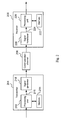
- FIG. 2 shows a digital communication system for transmitting a data set over a communication channel 206, according to one embodiment.
- the digital communication system comprises a transmitter 204 and a receiver 208.
- the transmitter 204 has a memory 214 for buffering the data set to be transmitted, a processing unit 212 to provide a formatted data frame 216 and a signal generator 218 for generating a signal including the formatted data frame 216 for transmission over the communication channel 206.
- the processing unit 212 provides a header comprising a cyclic redundancy checksum calculated as previously described and combines the header and the data set to provide the formatted data frame 216.
- the receiver 208 has a signal transducer 220 for converting the received signal to a received formatted data frame 224, a processing unit 212 to retrieve the received data set and a memory 222 for buffering the received data set.
- the processing unit 212 may check for the presence of an error on the received data set using the cyclic redundancy checksum included in the received formatted data frame 224.
- FIG. 3 illustrates one specific application of a digital communication system.
- the Electronic Engine Control 304 provides data from engine 302, such as for monitoring and maintenance purposes. This data is transmitted to the Ground Support Equipment (GSE) 308 via a GSE connector 306, and to any Health Usage Monitoring System or Digital Transmission Unit (HUMS/DTU) 310 using the transmission format previously described.
- the EEC 304 comprises a transmitter, such as transmitter 204 from Fig. 2
- each of the GSE connector 306 and the HUMS/DTU 310 comprises a receiver, such as receiver 208 from Fig. 2 , to communicate engine data.
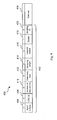
- Figure 4 illustrates an example of a formatted data frame 400.
- the formatted data frame 400 is adapted for communication of engine data by an Electronic Engine Control as described hereinabove.
- the formatted data frame 400 consists of two data groups, the first group being a header 402 comprising a plurality of header fields 406, 408, 410, 412, 414, 416, 418, 420 and the second group being engine data collected by the Electronic Engine Control and grouped in a data set 404.
- the header 402 consists of eight header fields 406, 408, 410, 412, 414, 416, 418, 420.
- a first field 406 is an 1-byte alternating synchronization/counter synchronization pattern. It is used by external software tools to synchronize to the data stream and to distinguish one data frame from the next.
- a second field, the redundancy field 408, is a 32-bit (4-byte) cyclic redundancy checksum (CRC) that is based on a standard specified by the International Telecommunications Union (ITU), ITU-TSS CRC32 and using a polynomial of 04CI 1DB7 hexadecimal.
- the CRC is calculated based on the remaining six header fields 410, 412, 414, 416, 418, 420 and the data set 404 before the entire formatted data frame is output by the transmitter. It provides a reliable method by which data corruption can be detected. This provision makes it possible to record and transport the data by wireless technology, aircraft telemetry, or by such means as FTP file transfer and still be able to verify the integrity of the data at any time. It may be useful in legal proceedings should the data integrity come under scrutiny.
- a third field 410 is an 8-bit value indicating the number of data entries in the data set 404 and a fourth field 412 is a 4-bit value indicating the size of each of the data entries to be transmitted using the formatted data frame 400.
- the size of the data entries can be specified according to Table 1.
- a fifth field 414 and a sixth field 416 are provisions for such devices as Health Usage Monitoring Systems (HUMS) or Data Transmission Units (DTU). They provide general information for such devices that allows them to determine when to record information and to allocate a level of importance to the recorded data for resolution purposes. It provides general information to provision for such devices where the device vendor could configure their HUMS or DTU according to the device capabilities or limitations.
- the fifth field 414 is a 4-bit value that is used to weight real time display data for the HUMS/DTU or the GBS data frame capture or sampling rate as defined in Table 2. Table 2 : Real time display data frame sampling rate Sampling Weight Code Definition 0 Fast (Fault or Surge) 1 Medium (Event or Exceedance) 2 Slow (Trend Monitoring) 3-15 Spare
- the sixth field 416 is a 1-bit value that is used by the Electronic Engine Control in conjunction with a DTU signal to specify to the DTU that it may enable its transmitter.
- a seventh field 418 is a 7-bit value providing information as to the type of engine data being transmitted. This field informs the receiver as to which translation file to access so as to be able to decrypt engine data in the data set 404.
- An eighth field 420 is an 8-bit string dedicated to a series of scrolling ASCII character strings. Each successive formatted data frame contains one of such ASCII character. Since the data frames are received sequentially, the individual characters can be assembled into strings of information.
- the software identifier of the EEC and the serial number of the engine to which the EEC is coupled can be included. The aircraft identification number is a possible character string.
- the EEC software identifier character string allows for the receiver to automatically configure itself to access the correct set of translation files to interpret the engine data in the data set 404.
- the seventh field 418 is used to select the correct translation file from the complete set of such translation files for a given EEC software version.
- the engine serial number ensures that the data is allocated to the correct turbo machine.
- the checksum of the present approach does not require the remainder of the data communication to have a fixed length. This allows the engine control system to "grow" over time - for example, new functionality can be added, new information communicated in the protocol, just by adding the appropriate new header elements - the protocol is not static, or fixed in time, but permits the communicated data to be reprogrammed and thereby evolve without having to modify the basic elements of the protocol.
- the fifth, the sixth or the seventh field could be omitted or replace by other header field if the described communication format is to be used for applications other than an aircraft engine monitoring application. Additional header elements may be added.
- the illustrated embodiment uses a 32-bit cyclic redundancy checksum, but a 16-bit or 64-bit cyclic redundancy checksum could be used instead. Other suitable types of checksum arrangements of data integrity mechanisms may be used instead of, or in conjunction with, a cyclic redundancy checksum. Still other modifications which fall within the scope of the present invention will be apparent to those skilled in the art, in light of a review of this disclosure, and such modifications are intended to fall within the appended claims.
Landscapes
- Engineering & Computer Science (AREA)
- Computer Networks & Wireless Communication (AREA)
- Signal Processing (AREA)
- Detection And Prevention Of Errors In Transmission (AREA)
- Communication Control (AREA)
Abstract
Description
- The invention relates generally to serial digital communication and, more particularly, to improved communication formats.
- In aircraft applications, an Electronic Engine Control (EEC) provides monitoring and maintenance data transmitted to onboard Health Usage Monitoring Systems (HUMS) or Data Transmission Units (DTU) and transmitted to the Ground Support Equipment (GSE) on landing. Data stored during the flight is transmitted to the GSE using the airframe GSE connector, for maintenance purposes. The type of engine data to be transmitted may vary. However, if the data varies, the communication protocol may have to be altered to accommodate the variance.
- Accordingly, there is a need to provide an improved serial digital communication protocol.
- In one aspect, provided is a method for formatting a data set for transmission on a communication channel, the method comprising: buffering the data set to be transmitted; providing a header having a plurality of header fields comprising a redundancy field having a cyclic redundancy checksum calculated on data in part of the header fields and on the data set; and combining the header and the data set to provide a formatted data frame to be transmitted on the communication channel.
- In another aspect, provided is a digital data communication transmitter for transmitting a data set, the transmitter comprising: a memory for buffering the data set; a processing unit for providing a header having a plurality of header fields comprising a redundancy field comprising a cyclic redundancy checksum calculated on data in part of the header fields and on the data set, and for combining the header and the data set to provide a formatted data frame; and a signal generator for transmitting the formatted data frame.
- In yet another aspect, provided is an apparatus for formatting a data set for transmission over a communication channel, the apparatus having a memory for buffering the data set; and a processing unit for formatting the data set and providing a formatted data frame, the formatted data frame comprising: a header having a plurality of header fields comprising a redundancy field with a cyclic redundancy checksum calculated on data in part of the header fields and on the data set; and the data set.
- In still another aspect, provided is an apparatus for retrieving a data set from a formatted data frame to be used in a communication channel, the apparatus having a memory for buffering the data set; and a processing unit for retrieving the data set from the formatted data frame, the formatted data frame comprising: a header having a plurality of header fields comprising a redundancy field with a cyclic redundancy checksum calculated on data in part of the header fields and on the data set; and the data set.
- Further details of these and other aspects of the present invention will be apparent from the detailed description and figures included below.
- Reference is now made to the accompanying figures, in which:
-
Figure 1 is a flowchart which illustrates a method for formatting a data set for transmission on a communication channel; -
Figure 2 is a block diagram which shows a digital communication system for transmitting a data set over a communication channel; -
Figure 3 is a block diagram which illustrates one specific application of a digital communication system, wherein the transmitter is an Electronic Engine Control; and -
Figure 4 is a schematic diagram which illustrates an example of a formatted data frame. - A method for formatting a data set for transmission on a communication channel, is illustrated in
Figure 1 . Instep 102, the data set to be transmitted is buffered. Instep 104, a header is provided. The header has a plurality of header fields comprising a redundancy field. The redundancy field contains a cyclic redundancy checksum calculated on the data set and on data in at least part of the header fields, excluding the redundancy field. The cyclic redundancy checksum may be based on the International Telecommunications Union ITU-TSS CRC-32 standard using a polynomial of 04C11DB7 hexadecimal, or may be calculated using any other cyclic redundancy checksum method known in the art. It is to be noted that any CRC algorithm - or even simple checksum routine - can be used. The one described above could be seeded with a different polynomial, the size of the CRC could be varied (need not be 4 bytes), etc. A CRC algorithm is a simple checksum. One of the CRC's characteristic is of being able to permit corrupted data to be rebuilt, depending on the extent of corruption and the size of the CRC. Instep 106, the header and the data set are combined to provide a formatted data frame to be transmitted on the communication channel. This method provides a communication format including a redundancy checksum for error detection and allowing transmission of a data set of variable length. The data set may comprise a variable number of data entries all having the same variable size. In the latter case, the header should comprise a number field for indicating the number of data entries and a size field for indicating the size of each data entry. This allows evolution of the format over time by adding new functionalities or communicating new types of data entries. The formatted data frame may be transmitted using an RS-422 UART communication protocol or any appropriate communication protocol as known by one skilled in the art. -
Figure 2 shows a digital communication system for transmitting a data set over acommunication channel 206, according to one embodiment. The digital communication system comprises atransmitter 204 and areceiver 208. Thetransmitter 204 has amemory 214 for buffering the data set to be transmitted, aprocessing unit 212 to provide a formatteddata frame 216 and asignal generator 218 for generating a signal including the formatteddata frame 216 for transmission over thecommunication channel 206. Theprocessing unit 212 provides a header comprising a cyclic redundancy checksum calculated as previously described and combines the header and the data set to provide the formatteddata frame 216. Thereceiver 208 has asignal transducer 220 for converting the received signal to a received formatteddata frame 224, aprocessing unit 212 to retrieve the received data set and amemory 222 for buffering the received data set. Theprocessing unit 212 may check for the presence of an error on the received data set using the cyclic redundancy checksum included in the received formatteddata frame 224. -
Figure 3 illustrates one specific application of a digital communication system. The Electronic Engine Control 304 (EEC) provides data fromengine 302, such as for monitoring and maintenance purposes. This data is transmitted to the Ground Support Equipment (GSE) 308 via aGSE connector 306, and to any Health Usage Monitoring System or Digital Transmission Unit (HUMS/DTU) 310 using the transmission format previously described. In this embodiment, theEEC 304 comprises a transmitter, such astransmitter 204 fromFig. 2 , and each of theGSE connector 306 and the HUMS/DTU 310 comprises a receiver, such asreceiver 208 fromFig. 2 , to communicate engine data. - This specific application described herein is not intended to be the exclusive embodiment of the present concept. The communication format may be applied to any suitable application where serial digital communication is required.
-
Figure 4 illustrates an example of a formatteddata frame 400. The formatteddata frame 400 is adapted for communication of engine data by an Electronic Engine Control as described hereinabove. According to one communication format, the formatteddata frame 400 consists of two data groups, the first group being aheader 402 comprising a plurality ofheader fields data set 404. - In this embodiment, the
header 402 consists of eightheader fields first field 406 is an 1-byte alternating synchronization/counter synchronization pattern. It is used by external software tools to synchronize to the data stream and to distinguish one data frame from the next. - A second field, the
redundancy field 408, is a 32-bit (4-byte) cyclic redundancy checksum (CRC) that is based on a standard specified by the International Telecommunications Union (ITU), ITU-TSS CRC32 and using a polynomial of 04CI 1DB7 hexadecimal. The CRC is calculated based on the remaining sixheader fields - A
third field 410 is an 8-bit value indicating the number of data entries in thedata set 404 and afourth field 412 is a 4-bit value indicating the size of each of the data entries to be transmitted using the formatteddata frame 400. For example, the size of the data entries can be specified according to Table 1. These fields, coupled with the first field 406 (synch/counter synch field), allow for the synch/counter synch bit pattern to be present in the engine data, a situation that is otherwise impossible for a receiver to synchronize to the beginning of a data frame. Once a synch/counter synch pattern is detected by the receiver, it can use the information contained in thethird field 410 andfourth field 412 to project where the counter synch should be located. If it is unsuccessful in its first attempt to locate the counter synch, it scans linearly through the buffered data until it locates the next instance of the synch pattern. It repeats this cycle until it is successful and synchronizes onto the beginning of the data frame. It can then translate the information using an appropriate translation file. These fields are also used in varying the engine data entry size and the number of such data entry in adata set 404 to vary, providing flexibility from engine application to engine application while allowing the receiver to maintain a constant approach to achieving synchronization.Table 1: Size definitions Type Value Individual Data Size 0 Byte 1 Word (16-bits) 2 DCU Block (132 bytes) 3 Dword (32-bits) 4 EEC EEPROM (132 bytes) 5-15 Spare - A
fifth field 414 and asixth field 416 are provisions for such devices as Health Usage Monitoring Systems (HUMS) or Data Transmission Units (DTU). They provide general information for such devices that allows them to determine when to record information and to allocate a level of importance to the recorded data for resolution purposes. It provides general information to provision for such devices where the device vendor could configure their HUMS or DTU according to the device capabilities or limitations. Thefifth field 414 is a 4-bit value that is used to weight real time display data for the HUMS/DTU or the GBS data frame capture or sampling rate as defined in Table 2.Table 2 : Real time display data frame sampling rate Sampling Weight Code Definition 0 Fast (Fault or Surge) 1 Medium (Event or Exceedance) 2 Slow (Trend Monitoring) 3-15 Spare - The
sixth field 416 is a 1-bit value that is used by the Electronic Engine Control in conjunction with a DTU signal to specify to the DTU that it may enable its transmitter. - A
seventh field 418 is a 7-bit value providing information as to the type of engine data being transmitted. This field informs the receiver as to which translation file to access so as to be able to decrypt engine data in thedata set 404. - An
eighth field 420 is an 8-bit string dedicated to a series of scrolling ASCII character strings. Each successive formatted data frame contains one of such ASCII character. Since the data frames are received sequentially, the individual characters can be assembled into strings of information. The software identifier of the EEC and the serial number of the engine to which the EEC is coupled can be included. The aircraft identification number is a possible character string. The EEC software identifier character string allows for the receiver to automatically configure itself to access the correct set of translation files to interpret the engine data in thedata set 404. Theseventh field 418 is used to select the correct translation file from the complete set of such translation files for a given EEC software version. The engine serial number ensures that the data is allocated to the correct turbo machine. - The checksum of the present approach does not require the remainder of the data communication to have a fixed length. This allows the engine control system to "grow" over time - for example, new functionality can be added, new information communicated in the protocol, just by adding the appropriate new header elements - the protocol is not static, or fixed in time, but permits the communicated data to be reprogrammed and thereby evolve without having to modify the basic elements of the protocol.
- The above description is meant to be exemplary only, and one skilled in the art will recognize that changes may be made to the embodiments described without departing from the scope of the invention disclosed. For example, the fifth, the sixth or the seventh field could be omitted or replace by other header field if the described communication format is to be used for applications other than an aircraft engine monitoring application. Additional header elements may be added. Also, the illustrated embodiment uses a 32-bit cyclic redundancy checksum, but a 16-bit or 64-bit cyclic redundancy checksum could be used instead. Other suitable types of checksum arrangements of data integrity mechanisms may be used instead of, or in conjunction with, a cyclic redundancy checksum. Still other modifications which fall within the scope of the present invention will be apparent to those skilled in the art, in light of a review of this disclosure, and such modifications are intended to fall within the appended claims.
Claims (17)
- A method for formatting a data set (404) for transmission on a communication channel, said method comprising:buffering said data set (404) to be transmitted;providing a header (402) having a plurality of header fields (406 ... 420) comprising a redundancy field (408) having a checksum calculated on data in part of said header fields (406 ... 420) and on said data set (404); andcombining said header (402) and said data set (404) to provide a formatted data frame (400) to be transmitted on said communication channel.
- The method as defined in claim 1, wherein said checksum comprises a cyclic redundancy checksum.
- The method as defined in claim 1 or 2, wherein said checksum is calculated on data excluding said redundancy field.
- The method as defined in claim 1, 2, or 3, wherein said data set (406) has a variable length hence providing expandability.
- The method as defined in any preceding claim, wherein said data set (404) comprises a variable number of data entries all having the same variable size and wherein said plurality of header fields (406 ... 420) further comprises a number field (410) for indicating said number and a size field (412) for indicating said size.
- The method as defined in any preceding claim, wherein said data set (404) comprises data entries of variable data type, all data entries of said data set (404) having the same data type and wherein said plurality of header fields (406 ... 420) further comprises a data type field (418) for indicating said data type.
- The method as defined in any preceding claim, wherein said plurality of header fields (406 ... 420) further comprises an instruction field for instructing a receiving unit to perform an action.
- The method as defined in any preceding claim, wherein said redundancy field (408) is for use in error detection.
- The method as defined in any preceding claim, wherein said formatted data frame (400) is to be transmitted using an RS-422 UART communication protocol.
- The method as defined in any preceding claim, wherein said cyclic redundancy checksum is based on the ITU-TSS CRC-32 standard using a polynomial of 04CI 1DB7 hexadecimal.
- A digital data communication transmitter (204) for transmitting a data set (404), said transmitter comprising:a memory (214) for buffering said data set (404);a processing unit (212) for providing a header (402) having a plurality of header fields (406 ... 420) comprising a redundancy field (404) comprising a checksum calculated on data in part of said header fields (406 ... 420) and on said data set (404), and for combining said header (402) and said data set (404) to provide a formatted data frame (400); anda signal generator (218) for transmitting said formatted data frame (400).
- The digital data communication transmitter as defined in claim 11, wherein said data set (404) has a variable length hence providing expandability.
- The digital data communication transmitter as defined in claim 11 or 12, wherein said data set (404) comprises a variable number of data entries all having the same variable size and wherein said plurality of header fields (406 ... 420) further comprises a number field (410) for indicating said number and a size field (412) for indicating said size.
- The digital data communication transmitter as defined in claim 11, 12 or 13 wherein said data set (404) comprises data entries of variable data type, all data of said data set (404) having the same data type and wherein said plurality of header fields (406 ... 420) further comprises a data type field (418) for indicating said data type.
- An apparatus for formatting a data set (404) for transmission over a communication channel (206), the apparatus having a memory (214) for buffering said data set (404); and a processing unit (212) for formatting said data set (404) and providing a formatted data frame (400), said formatted data frame (400) comprising:a header (402) having a plurality of header fields (406 ... 420) comprising a redundancy field (408) with a checksum calculated on data in part of said header fields (406 ... 420) and on said data set (404); andsaid data set (404).
- An apparatus (208) for retrieving a data set (404) from a formatted data frame (400) to be used in a communication channel (206), the apparatus having a memory (222) for buffering said data set (404); and a processing unit (206) for retrieving said data set (404) from said formatted data frame (400), said formatted data frame (400) comprising:a header (402) having a plurality of header fields (406 ... 420) comprising a redundancy field (418) with a checksum calculated on data in part of said header fields (406 ... 420) and on said data set (404); andsaid data set (404).
- The apparatus as defined in claim 15 or 16, wherein said data set (404) comprises a variable number of data entries all having the same variable size and wherein said plurality of header fields (406 ... 420) further comprises a number field (410) for indicating said number and a size field (412) for indicating said size.
Applications Claiming Priority (1)
| Application Number | Priority Date | Filing Date | Title |
|---|---|---|---|
| US11/615,240 US8363541B2 (en) | 2006-12-22 | 2006-12-22 | Serial digital communication protocol |
Publications (3)
| Publication Number | Publication Date |
|---|---|
| EP1940069A2 true EP1940069A2 (en) | 2008-07-02 |
| EP1940069A3 EP1940069A3 (en) | 2008-07-30 |
| EP1940069B1 EP1940069B1 (en) | 2011-10-12 |
Family
ID=39409982
Family Applications (1)
| Application Number | Title | Priority Date | Filing Date |
|---|---|---|---|
| EP07254322A Active EP1940069B1 (en) | 2006-12-22 | 2007-10-31 | Serial digital communication protocol |
Country Status (4)
| Country | Link |
|---|---|
| US (1) | US8363541B2 (en) |
| EP (1) | EP1940069B1 (en) |
| CA (1) | CA2671712C (en) |
| WO (1) | WO2008077228A1 (en) |
Cited By (1)
| Publication number | Priority date | Publication date | Assignee | Title |
|---|---|---|---|---|
| US11618585B2 (en) | 2019-10-10 | 2023-04-04 | Ge Aviation Systems Limited | Integrated system for improved vehicle maintenance and safety |
Families Citing this family (4)
| Publication number | Priority date | Publication date | Assignee | Title |
|---|---|---|---|---|
| US9178757B2 (en) * | 2013-12-31 | 2015-11-03 | General Electric Company | Serial link fault detection system and method |
| CN105187420B (en) * | 2015-08-27 | 2018-03-30 | 哈尔滨工业大学 | A kind of communications protocol matching process based on RS422 buses |
| CN114691412A (en) * | 2020-12-29 | 2022-07-01 | 华为技术有限公司 | A data verification method and related equipment |
| CN115079643A (en) * | 2021-03-16 | 2022-09-20 | 苏州艾利特机器人有限公司 | A field bus and industrial robot for multiaxis motion control system |
Citations (3)
| Publication number | Priority date | Publication date | Assignee | Title |
|---|---|---|---|---|
| EP0470451A2 (en) | 1990-08-07 | 1992-02-12 | National Semiconductor Corporation | Implementation of the high-level data link control cyclic redundancy check (HDLC CRC) calculation |
| US5898712A (en) | 1996-09-25 | 1999-04-27 | Mitsubishi Denki Kabushiki Kaisha | CRC code generation circuit, code error detection circuit, and CRC circuit having functions of both the CRC code generation circuit and the code error detection circuit |
| US20050257117A1 (en) | 2004-05-12 | 2005-11-17 | Weirong Chiang | Method and circuit for determining an ending of an ethernet frame |
Family Cites Families (17)
| Publication number | Priority date | Publication date | Assignee | Title |
|---|---|---|---|---|
| US5668803A (en) | 1989-06-29 | 1997-09-16 | Symbol Technologies, Inc. | Protocol for packet data communication system |
| US5491719A (en) | 1993-07-02 | 1996-02-13 | Telefonaktiebolaget Lm Ericsson | System for handling data errors on a cellular communications system PCM link |
| US5553302A (en) | 1993-12-30 | 1996-09-03 | Unisys Corporation | Serial I/O channel having independent and asynchronous facilities with sequence recognition, frame recognition, and frame receiving mechanism for receiving control and user defined data |
| US6310884B1 (en) * | 1998-05-21 | 2001-10-30 | Lsi Logic Corporation | Data transfer method and apparatus that allocate storage based upon a received relative offset |
| US6269099B1 (en) * | 1998-07-01 | 2001-07-31 | 3Com Corporation | Protocol and method for peer network device discovery |
| US6243733B1 (en) * | 1998-09-16 | 2001-06-05 | Cirrus Logic, Inc. | Correct carry bit generation |
| US6909717B1 (en) * | 1998-10-21 | 2005-06-21 | Peter Higgins | Real time ethernet protocol |
| US6609167B1 (en) | 1999-03-17 | 2003-08-19 | Adaptec, Inc. | Host and device serial communication protocols and communication packet formats |
| US6618383B1 (en) * | 1999-12-28 | 2003-09-09 | Nortel Networks Limited | Serial interface for a broadband communications network |
| US6944163B2 (en) * | 2000-02-09 | 2005-09-13 | Nortel Networks Limited | 10 Gigabit ethernet mappings for a common LAN/WAN PMD interface with a simple universal physical medium dependent interface |
| US6836869B1 (en) * | 2001-02-02 | 2004-12-28 | Cradle Technologies, Inc. | Combined cyclic redundancy check (CRC) and Reed-Solomon (RS) error checking unit |
| JP3690316B2 (en) * | 2001-08-10 | 2005-08-31 | ソニー株式会社 | Data transmission system, header information addition device, data format conversion device, and data transmission method |
| WO2004008760A1 (en) * | 2002-07-16 | 2004-01-22 | Matsushita Electric Industrial Co., Ltd. | Content receiving apparatus and content transmitting apparatus |
| KR100933167B1 (en) * | 2002-10-02 | 2009-12-21 | 삼성전자주식회사 | Transmission Method for Authentication and Privacy Guarantee in Tree-structured Networks |
| US20050010925A1 (en) * | 2003-07-10 | 2005-01-13 | Charbel Khawand | Interprocessor communication protocol with smart streaming port |
| US7325060B2 (en) * | 2004-03-15 | 2008-01-29 | Micrel, Inc. | Management system for hardware network devices |
| US20060221953A1 (en) * | 2005-04-01 | 2006-10-05 | Claude Basso | Method and apparatus for blind checksum and correction for network transmissions |
-
2006
- 2006-12-22 US US11/615,240 patent/US8363541B2/en not_active Expired - Fee Related
-
2007
- 2007-05-16 WO PCT/CA2007/000880 patent/WO2008077228A1/en active Application Filing
- 2007-05-16 CA CA2671712A patent/CA2671712C/en active Active
- 2007-10-31 EP EP07254322A patent/EP1940069B1/en active Active
Patent Citations (3)
| Publication number | Priority date | Publication date | Assignee | Title |
|---|---|---|---|---|
| EP0470451A2 (en) | 1990-08-07 | 1992-02-12 | National Semiconductor Corporation | Implementation of the high-level data link control cyclic redundancy check (HDLC CRC) calculation |
| US5898712A (en) | 1996-09-25 | 1999-04-27 | Mitsubishi Denki Kabushiki Kaisha | CRC code generation circuit, code error detection circuit, and CRC circuit having functions of both the CRC code generation circuit and the code error detection circuit |
| US20050257117A1 (en) | 2004-05-12 | 2005-11-17 | Weirong Chiang | Method and circuit for determining an ending of an ethernet frame |
Cited By (1)
| Publication number | Priority date | Publication date | Assignee | Title |
|---|---|---|---|---|
| US11618585B2 (en) | 2019-10-10 | 2023-04-04 | Ge Aviation Systems Limited | Integrated system for improved vehicle maintenance and safety |
Also Published As
| Publication number | Publication date |
|---|---|
| US8363541B2 (en) | 2013-01-29 |
| EP1940069A3 (en) | 2008-07-30 |
| US20080151883A1 (en) | 2008-06-26 |
| CA2671712C (en) | 2013-07-09 |
| CA2671712A1 (en) | 2008-07-03 |
| WO2008077228A1 (en) | 2008-07-03 |
| EP1940069B1 (en) | 2011-10-12 |
Similar Documents
| Publication | Publication Date | Title |
|---|---|---|
| EP1940069B1 (en) | Serial digital communication protocol | |
| US11100823B2 (en) | System and method for wireless control of signs | |
| CN112491457A (en) | Satellite on-orbit reconstruction method, device, system, equipment and storage medium | |
| CN106648765A (en) | Embedded device firmware service pack generating and firmware differential upgrading methods and device | |
| EP0793174A3 (en) | Error detection and correction method and apparatus for computer memory | |
| CN101588370A (en) | Analytic method of multirate communication data stream format | |
| WO1999024909A1 (en) | Apparatus and method for applying crc to arinc 429 periodic data | |
| US7373525B2 (en) | Data processing method and data checking method | |
| KR101341041B1 (en) | Operation method of RFID Tag, operation method of RFID Reader, RFID Tag and RFID Reader | |
| CN111191346A (en) | Method and medium for restoring on-orbit operation instance data of spacecraft software | |
| CN110868272A (en) | High code rate satellite real-time quick-look processing system and method based on server cluster | |
| CN1909669B (en) | Method, and device for receiving data stream | |
| US6041434A (en) | Code generator for selectively producing cyclic redundancy check data codes different in data length | |
| EP0315699B1 (en) | Method and system for checking errors of signal being transferred through transmission line | |
| CN113641953B (en) | Gyroscope transmission frame format data analysis method, data encapsulation method and system | |
| CN112104795B (en) | Analog camera and image acquisition system | |
| CN1205778C (en) | Method and apparatus for data transmission, and method and apparatus for data reception | |
| JPH08279799A (en) | Parallel data transmitter | |
| CN118979728B (en) | A service table for polling downhole instrument data in logging while drilling | |
| Syafrudin et al. | Development of payload data handling streaming verification based on FPGA | |
| CN100418312C (en) | Digital data transmission error detection method and system | |
| CN116451623A (en) | Universal simulation system and method suitable for data processing FPGA | |
| CN118870500A (en) | Industrial equipment characteristic value synchronization method and system based on wireless sensor | |
| CN118368224A (en) | Wind power generation slip ring communication auxiliary monitoring method and system | |
| CN118963657A (en) | Multi-stage telemetry data memory storage method and system |
Legal Events
| Date | Code | Title | Description |
|---|---|---|---|
| PUAI | Public reference made under article 153(3) epc to a published international application that has entered the european phase |
Free format text: ORIGINAL CODE: 0009012 |
|
| PUAL | Search report despatched |
Free format text: ORIGINAL CODE: 0009013 |
|
| AK | Designated contracting states |
Kind code of ref document: A2 Designated state(s): AT BE BG CH CY CZ DE DK EE ES FI FR GB GR HU IE IS IT LI LT LU LV MC MT NL PL PT RO SE SI SK TR |
|
| AX | Request for extension of the european patent |
Extension state: AL BA HR MK RS |
|
| AK | Designated contracting states |
Kind code of ref document: A3 Designated state(s): AT BE BG CH CY CZ DE DK EE ES FI FR GB GR HU IE IS IT LI LT LU LV MC MT NL PL PT RO SE SI SK TR |
|
| AX | Request for extension of the european patent |
Extension state: AL BA HR MK RS |
|
| 17P | Request for examination filed |
Effective date: 20081006 |
|
| 17Q | First examination report despatched |
Effective date: 20081111 |
|
| AKX | Designation fees paid |
Designated state(s): DE FR GB |
|
| GRAP | Despatch of communication of intention to grant a patent |
Free format text: ORIGINAL CODE: EPIDOSNIGR1 |
|
| RIN1 | Information on inventor provided before grant (corrected) |
Inventor name: MARK, BILL Inventor name: COCKERELL, GEOFFREY |
|
| GRAS | Grant fee paid |
Free format text: ORIGINAL CODE: EPIDOSNIGR3 |
|
| GRAA | (expected) grant |
Free format text: ORIGINAL CODE: 0009210 |
|
| AK | Designated contracting states |
Kind code of ref document: B1 Designated state(s): DE FR GB |
|
| REG | Reference to a national code |
Ref country code: GB Ref legal event code: FG4D |
|
| REG | Reference to a national code |
Ref country code: DE Ref legal event code: R096 Ref document number: 602007017748 Country of ref document: DE Effective date: 20120112 |
|
| PLBE | No opposition filed within time limit |
Free format text: ORIGINAL CODE: 0009261 |
|
| STAA | Information on the status of an ep patent application or granted ep patent |
Free format text: STATUS: NO OPPOSITION FILED WITHIN TIME LIMIT |
|
| 26N | No opposition filed |
Effective date: 20120713 |
|
| REG | Reference to a national code |
Ref country code: DE Ref legal event code: R097 Ref document number: 602007017748 Country of ref document: DE Effective date: 20120713 |
|
| REG | Reference to a national code |
Ref country code: FR Ref legal event code: PLFP Year of fee payment: 10 |
|
| REG | Reference to a national code |
Ref country code: DE Ref legal event code: R082 Ref document number: 602007017748 Country of ref document: DE Representative=s name: SCHMITT-NILSON SCHRAUD WAIBEL WOHLFROM PATENTA, DE |
|
| REG | Reference to a national code |
Ref country code: FR Ref legal event code: PLFP Year of fee payment: 11 |
|
| REG | Reference to a national code |
Ref country code: FR Ref legal event code: PLFP Year of fee payment: 12 |
|
| PGFP | Annual fee paid to national office [announced via postgrant information from national office to epo] |
Ref country code: DE Payment date: 20190918 Year of fee payment: 13 |
|
| REG | Reference to a national code |
Ref country code: DE Ref legal event code: R119 Ref document number: 602007017748 Country of ref document: DE |
|
| PG25 | Lapsed in a contracting state [announced via postgrant information from national office to epo] |
Ref country code: DE Free format text: LAPSE BECAUSE OF NON-PAYMENT OF DUE FEES Effective date: 20210501 |
|
| P01 | Opt-out of the competence of the unified patent court (upc) registered |
Effective date: 20230530 |
|
| PGFP | Annual fee paid to national office [announced via postgrant information from national office to epo] |
Ref country code: GB Payment date: 20240919 Year of fee payment: 18 |
|
| PGFP | Annual fee paid to national office [announced via postgrant information from national office to epo] |
Ref country code: FR Payment date: 20240919 Year of fee payment: 18 |