EP1939995A2 - Methods and systems for detecting series arcs in electrical systems - Google Patents
Methods and systems for detecting series arcs in electrical systems Download PDFInfo
- Publication number
- EP1939995A2 EP1939995A2 EP07123439A EP07123439A EP1939995A2 EP 1939995 A2 EP1939995 A2 EP 1939995A2 EP 07123439 A EP07123439 A EP 07123439A EP 07123439 A EP07123439 A EP 07123439A EP 1939995 A2 EP1939995 A2 EP 1939995A2
- Authority
- EP
- European Patent Office
- Prior art keywords
- features
- peak
- signal
- filtered signal
- maximum
- Prior art date
- Legal status (The legal status is an assumption and is not a legal conclusion. Google has not performed a legal analysis and makes no representation as to the accuracy of the status listed.)
- Withdrawn
Links
- 238000000034 method Methods 0.000 title claims abstract description 35
- 239000004020 conductor Substances 0.000 claims abstract description 11
- 238000003066 decision tree Methods 0.000 claims description 6
- 238000004422 calculation algorithm Methods 0.000 claims description 4
- 238000013528 artificial neural network Methods 0.000 claims description 3
- 238000012545 processing Methods 0.000 claims description 3
- 238000007637 random forest analysis Methods 0.000 claims description 3
- 238000012706 support-vector machine Methods 0.000 claims description 3
- 238000013459 approach Methods 0.000 abstract description 5
- 238000003909 pattern recognition Methods 0.000 abstract description 3
- 238000000605 extraction Methods 0.000 description 15
- 238000013461 design Methods 0.000 description 10
- 238000001914 filtration Methods 0.000 description 2
- 230000001143 conditioned effect Effects 0.000 description 1
- 230000002939 deleterious effect Effects 0.000 description 1
- 238000010586 diagram Methods 0.000 description 1
- 230000004069 differentiation Effects 0.000 description 1
- 239000003607 modifier Substances 0.000 description 1
- 230000007935 neutral effect Effects 0.000 description 1
- 230000000737 periodic effect Effects 0.000 description 1
- 238000012360 testing method Methods 0.000 description 1
Images



Classifications
-
- G—PHYSICS
- G01—MEASURING; TESTING
- G01R—MEASURING ELECTRIC VARIABLES; MEASURING MAGNETIC VARIABLES
- G01R31/00—Arrangements for testing electric properties; Arrangements for locating electric faults; Arrangements for electrical testing characterised by what is being tested not provided for elsewhere
- G01R31/12—Testing dielectric strength or breakdown voltage ; Testing or monitoring effectiveness or level of insulation, e.g. of a cable or of an apparatus, for example using partial discharge measurements; Electrostatic testing
-
- H—ELECTRICITY
- H02—GENERATION; CONVERSION OR DISTRIBUTION OF ELECTRIC POWER
- H02H—EMERGENCY PROTECTIVE CIRCUIT ARRANGEMENTS
- H02H1/00—Details of emergency protective circuit arrangements
- H02H1/0092—Details of emergency protective circuit arrangements concerning the data processing means, e.g. expert systems, neural networks
-
- H—ELECTRICITY
- H02—GENERATION; CONVERSION OR DISTRIBUTION OF ELECTRIC POWER
- H02H—EMERGENCY PROTECTIVE CIRCUIT ARRANGEMENTS
- H02H1/00—Details of emergency protective circuit arrangements
- H02H1/0007—Details of emergency protective circuit arrangements concerning the detecting means
- H02H1/0015—Using arc detectors
Definitions
- the present disclosure is related to electrical systems. More particularly, the present disclosure is related to methods and systems for detecting series arcs in alternating current (AC) electrical systems.
- AC alternating current
- the electrical systems in residential, commercial, and industrial applications usually include a panel board for receiving electrical power from a utility source.
- the power is routed through the panel board to one or more current interrupters such as, but not limited to circuit breakers, trip units, and others.
- Each current interrupter distributes the power to a designated branch, where each branch supplies one or more loads with the power.
- the current interrupters are configured to interrupt the power to the particular branch if certain power conditions in that branch reach a predetermined set point.
- ground fault current interrupters can interrupt power due to a ground fault, and are commonly known as ground fault current interrupters (GFCI's).
- GFCI ground fault current interrupters
- the ground fault condition results when an imbalance of current flows between a line conductor and a neutral conductor, which could be caused by a leakage current or an arcing fault to ground.
- Arcing faults are commonly defined into two main categories, series arcs and parallel arcs. Series arcs can occur, for example, when current passes across a gap in a single conductor. Parallel arcs can occur, for example, when current passes between two conductors.
- a method of detecting a series arc in an alternating current electrical system is provided.
- the method is a pattern recognition based approach and includes passing raw current signals from a conductor in the electrical system through one or more filters to provide a filtered signal; extracting one or more features from the filtered signal; and classifying the features to determine if a series arc has occurred.
- the invention also provides a method of detecting a series arc in an alternating current electrical system that includes inputting raw current signals from a conductor in the electrical system into a one or more filters to provide a filtered signal; extracting a plurality of features from the filtered signal; and comparing the features to the known features representative of the series arc is also provided.
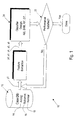
- Method 10 utilizes a pattern recognition approach to extract a plurality of features from the sensed current across a current interrupter and to determine which feature or subset of features can be used to detect series arcing events. In some embodiments, method 10 can determine the cause (e.g., compressor arc) of the detected series arcing event.
- cause e.g., compressor arc
- method 10 provides a tool that is useful in the recognition and differentiation of the current signal patterns that are indicative of normal and nuisance conditions, from current signal pattern(s) that are indicative of series arcing conditions.
- method 10 uses a data-driven approach to detect series arcing in AC electrical systems.
- Method 10 includes the use of a database 12.
- Database 12 includes a large number of raw signals (y 1 ) such as, but not limited to waveforms, measured from a plurality of conditions in an AC electrical system.
- raw signals (y 1 ) are measured by a bimetal of a current interrupter in a known manner.
- raw signals (y 1 ) include line current on a conductor in series with the bimetal.
- Database 12 includes the raw signals (y 1 ) from instances of arcing loads 14, both series and parallel, nuisance loads 16, and normal loads 18, where nuisance loads 16 include raw signals ( y 1 ) from one or more cases representing inrush signals.
- Method 10 inputs the raw signals ( y 1 ) from database 12 into a feature extraction step 20.
- Feature extraction step 20 passes or conditions the raw signals (y 1 ) through one or more filters 22 (only one shown) to provide filtered signal y 2 .
- filter 22 is shown as a high-pass filter.
- feature extraction step 20 can include one or more signal processing algorithms to, for example, filter out outlier signals and/or unusual signals.
- feature extraction step 20 uses filtered signal y 2 to calculate one or more features of the filtered signal.
- feature extraction step 20 is shown calculating three statistical features ( y 3 , y 4 , y 5 ) from filtered signal y 2 .
- feature y 3 is illustrated as the mean of filtered signal y 2
- feature y 4 is the standard deviation of the filtered signal
- feature y 5 is the difference between y 2 and y 3 .
- feature extraction step 20 is illustrated determining only three statistical features from filtered signal y 2 .
- feature extraction step 20 it is contemplated by the present disclosure for feature extraction step 20 to calculate any known features including, but not limited to, the mean of the full cycle, the standard deviation of the full cycle, the maximum standard deviation of a window of signal (where window width can vary) in the cycle, the minimum standard deviation of a window of signal in the cycle, the ratio of the maximum and minimum standard deviations, the absolute sum of each sample in the cycle, the relation of the standard deviations (or variances) for each adjacent window in the cycle, the RMS value, the difference between adjacent points for features such as, but not limited to, the maximum difference between two adjacent samples, the minimum difference between two adjacent samples, the ratio of the maximum difference to the minimum difference, the range of the signal differences (e.g., the maximum difference minus the minimum difference), the sum of the differences between adjacent points, the difference between adjacent points in the above mentioned first difference signal, features such as, but not limited to, the maximum difference between two adjacent samples, the minimum difference
- feature extraction step 20 measures and characterizes the signals/waveforms of the instances of arcing loads 14, nuisance loads 16, and normal loads 18 in database 12.
- Method 10 includes a classifier design step 24, which classifies the waveform features.
- Classifier design step 24 can be any classification system such as, but not limited to, a decision tree (DT), a neural network (NN), a random forest (RF), a support vector machine (SVM), any combinations thereof, and others.
- DT decision tree
- N neural network
- RF random forest
- SVM support vector machine
- a first exemplary embodiment of a classifier design step 24 is described herein with reference to FIGS. 3 through 8 as a decision tree.
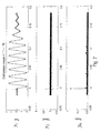
- FIG. 3 illustrates graphs comparing one or more cycles of raw signals, filtered signals, and corresponding extracted features ( y 1 , y 2 , y 3 , y 4 , y 5 ) representing an arcing condition 14 of a compressor.
- FIG. 4 illustrates graphs comparing one or more cycles of data ( y 1 , y 2 , y 3 , y 4 , y 5 ) representing nuisance (i.e., inrush) condition 16 of the compressor
- FIG. 5 illustrates graphs comparing one or more cycles of data ( y 1 , y 2 , y 3 , y 4 , y 5 ) representing a normal condition 18 of the compressor.
- the decision tree can be applied to more than one cycle of data.
- classifier design step 24 can, in some instances, determine particular features not possible when looking at only one cycle. For example, multiple cycles can be used to eliminate events that are periodic or one time to further differentiate between nuisance signals and arcing.
- classifier design step 24 classifies one or more particular features as indicators of, for example, a series arcing condition
- method 10 includes a testing step 26 shown in FIG. 1 .
- the particular identified feature(s) y 1 , y 2 , y 3 , y 4 , y 5
- the particular identified feature(s) can be tested against other instances of series arcing 14 in database 12 to determine whether the performance of the identified feature is acceptable, namely whether that feature is an effective indicator of the desired condition.
- method 10 when run on the data within database 12, properly indicate the desired condition, then method 10 is done and that feature can be used as a detector of the desired condition with desired performance. However, if the particular identified feature ( y 1 , y 2 , y 3 , y 4 , y 5 ), when run on the raw signals within database 12, does not properly indicate the desired condition, then method 10 returns to look at a different feature of the waveform.
- method 10 provides a data-driven approach that allows for extracting and selecting features from the waveform as being indicators of a particular condition such as, but not limited to, a series arc condition, a parallel arc condition, a normal condition, a nuisance condition, and any combinations thereof. Moreover, it is contemplated by the present disclosure for method 10 to find equal use as a detector of other conditions of the waveform such as, but not limited to, ground faults, and others.
- method 10 is configured to generate a number of different features, which are then used to differentiate the pattern of a series arcing signal from the pattern of normal conditioned signal and the signals with various nuisance loads.
- classifier design step 24 focuses on the signal peak signatures (y 6 ) of the features of the waveforms from feature extraction step 20.
- feature extraction step 20 for use with the second embodiment of classifier design step 24 can calculate signal peak signatures (y 6 ) by calculating any known peak domain feature including, but not limited to, minimum of peak amplitude, maximum of peak amplitude, difference of minimum and maximum amplitudes, mean of peak amplitude, standard deviation of amplitude, kurtosis of peak amplitude, skewness of peak amplitude, root mean square (RMS) of peak amplitude, crest factor of peak amplitude, number of peaks per unit time, and others.
- signal peak signatures y 6
- any known peak domain feature including, but not limited to, minimum of peak amplitude, maximum of peak amplitude, difference of minimum and maximum amplitudes, mean of peak amplitude, standard deviation of amplitude, kurtosis of peak amplitude, skewness of peak amplitude, root mean square (RMS) of peak amplitude, crest factor of peak amplitude, number of peaks per unit time, and others.
- feature extraction step 20 for use with the second embodiment of the classifier design step 24 can calculate signal peak signatures (y 6 ) by calculating any known peak shape statistics such as, but not limited to, the second order moment of shape, the third order moment of shape, the fourth order moment of shape, the time distance from maximum peak to centroids of peaks, and others.
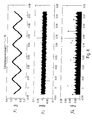
- FIG. 6 illustrates graphs comparing one or more cycles of data ( y 1 , y 2 , y 6 ) representing a series arcing condition 14 of the compressor from database 12.
- FIG. 7 illustrates graphs comparing one or more cycles of data ( y 1 , y 2 , y 6 ) representing nuisance (i.e., inrush) condition 16 of the compressor, while
- FIG. 8 illustrates graphs comparing one or more cycles of data (y 1 , y 2 , y 6 ) representing a normal condition 18 of the compressor.
- the graph of the peak features y 6 illustrates a unique burst pattern of current signal when series arcing occurs, where this same pattern is absent in the same peak feature (y 6 ) for the normal and nuisance conditions 16, 18 of FIGS. 7 and 8 .
- classifier design step 24 can identify this peak signature feature to detect series arcing.
- method 10 can be used to extract any number of discriminant features that characterize the current signals corresponding to different conditions (i.e., series arcing, parallel arcing, nuisance loads, normal loads, etc.) to accurately and reliably differentiate series arcing from normal operation of the AC electrical system.
- these features can be used in a system such as, but not limited to, an arc fault circuit interrupter (AFCI), to generate a trip signal so that the circuit is timely disconnected before the arc fault causes any further damages to other appliances connected in the system.
- AFCI arc fault circuit interrupter
- an AFCI can be provided that continuously compares current signals in the AC electrical system to features predetermined by method 10 to be indicative of a series arc fault and to use the outcome of this comparison to cause the AFCI to trip and protect the circuit and other appliances connected in the system.
- an enabled AFCI device can be configured to trip only when series arcing occurs.
- System 30 includes a signal source 32, a filter 34, and a microprocessor 36.
- Source 32 can be any desired source of raw current waveform signals (y 1 ). In one embodiment, source 32 can be database 12 discussed above. In another embodiment, source 32 is a bimetal of a current interrupter.
- Filter 34 is configured to condition raw signals ( y 1 ) and to provide filtered signals (y 2 ) to microprocessor 36.
- Filter 34 can be a filtering circuit, a filtering algorithm resident on microprocessor 36, and any combinations thereof.
- filter 34 can be a high-pass filter, a low-pass filter, a band-pass filter, a signal processing algorithm, and any combinations thereof.
- System 30 provides filtered signals ( y 2 ) from filter 34 to microprocessor 36.
- Microprocessor 36 is configured to generate one or more features ( y 3 , y 4 , y 5 , y 6 ) from filtered signal ( y 2 ). Further, microprocessor 36 is configured to compare the features ( y 3 , y 4 , y 5 , y 6 ) to one or more known features representative of particular conditions of the raw current waveform signals ( y 1 ).
- microprocessor 36 can compare the features ( y 3 , y 4 , y 5 , y 6 ) to one or more predetermined features resident on microprocessor, where the one or more predetermined features can be indicative of a condition such as a normal condition, a nuisance condition, a series arcing condition, a parallel arcing condition, a ground fault, and any combinations thereof.
- system 30 is configured to recognize and differentiate the raw current waveform signals ( y 1 ) that are indicative of normal and nuisance conditions, from raw current waveform signals ( y 1 ) that are indicative of a particular fault condition, such as series or parallel arcing conditions. Further, system 30 is configured to determine the cause of the particular fault condition (e.g., compressor series arc).
- a particular fault condition such as series or parallel arcing conditions.
- system 30 is resident on an arc fault circuit interrupter (AFCI).
- microprocessor 36 can provide a trip signal 38 to the arc fault circuit interrupter when system 30 detects one or more fault conditions.
Landscapes
- Engineering & Computer Science (AREA)
- Artificial Intelligence (AREA)
- Evolutionary Computation (AREA)
- Physics & Mathematics (AREA)
- General Physics & Mathematics (AREA)
- Testing Of Short-Circuits, Discontinuities, Leakage, Or Incorrect Line Connections (AREA)
- Emergency Protection Circuit Devices (AREA)
- Testing Relating To Insulation (AREA)
- Testing Electric Properties And Detecting Electric Faults (AREA)
- Image Analysis (AREA)
Abstract
A method of detecting a series arc in an alternating current electrical system is provided. The method is a pattern-recognition based approach and includes passing raw current signals (y 1) from a conductor in the electrical system through one or more filters (22) to provide a filtered signal (y 2); extracting one or more features (y 3, y 4 , y 5 ) from the filtered signal (y 2); and classifying the features to a known state representative of the series arc.
Description
- The present disclosure is related to electrical systems. More particularly, the present disclosure is related to methods and systems for detecting series arcs in alternating current (AC) electrical systems.
- The electrical systems in residential, commercial, and industrial applications usually include a panel board for receiving electrical power from a utility source. The power is routed through the panel board to one or more current interrupters such as, but not limited to circuit breakers, trip units, and others.
- Each current interrupter distributes the power to a designated branch, where each branch supplies one or more loads with the power. The current interrupters are configured to interrupt the power to the particular branch if certain power conditions in that branch reach a predetermined set point.
- For example, some current interrupters can interrupt power due to a ground fault, and are commonly known as ground fault current interrupters (GFCI's). The ground fault condition results when an imbalance of current flows between a line conductor and a neutral conductor, which could be caused by a leakage current or an arcing fault to ground.
- Other current interrupters can interrupt power due to an arcing fault, and are commonly known as arc fault current interrupters (AFCI's). Arcing faults are commonly defined into two main categories, series arcs and parallel arcs. Series arcs can occur, for example, when current passes across a gap in a single conductor. Parallel arcs can occur, for example, when current passes between two conductors.
- Unfortunately, arcing faults may not cause a conventional circuit interrupter to trip. This is particularly true when dealing with series arcing. Series arcing can potentially cause fires inside residential and commercial buildings. The potential for this to occur increases as homes become older.
- Accordingly, it has been determined by the present disclosure that there is a continuing need for methods of detecting series arcs in AC electrical systems that overcome, alleviate, and/or mitigate one or more of the aforementioned and other deleterious effects of prior art systems.
- According to the invention, a method of detecting a series arc in an alternating current electrical system is provided. The method is a pattern recognition based approach and includes passing raw current signals from a conductor in the electrical system through one or more filters to provide a filtered signal; extracting one or more features from the filtered signal; and classifying the features to determine if a series arc has occurred.
- The invention also provides a method of detecting a series arc in an alternating current electrical system that includes inputting raw current signals from a conductor in the electrical system into a one or more filters to provide a filtered signal; extracting a plurality of features from the filtered signal; and comparing the features to the known features representative of the series arc is also provided.
- The above-described and other features and advantages of the present disclosure will be appreciated and understood by those skilled in the art from the following detailed description with reference to the accompanying drawings, in which:
-
FIG. 1 is a block diagram of an exemplary embodiment of a method for detecting series arcing according to the present disclosure; -
FIG. 2 is a schematic depiction of an exemplary embodiment of a data feature extraction step according to the present disclosure; -
FIGS. 3 through 5 are graphs comparing one or more cycles of the extracted data in use in a first exemplary embodiment of the feature extraction step; -
FIGS. 6 through 8 illustrates graphs comparing multiple cycles of the extracted data in use in a second exemplary embodiment of the feature extraction step; and -
FIG. 9 is a schematic depiction of a system for detecting series arcing according to the present disclosure. - Referring to the drawings and in particular to
FIGS. 1 and2 , a method for detecting series arcing according to the present disclosure is shown and is generally referred to byreference numeral 10.Method 10 utilizes a pattern recognition approach to extract a plurality of features from the sensed current across a current interrupter and to determine which feature or subset of features can be used to detect series arcing events. In some embodiments,method 10 can determine the cause (e.g., compressor arc) of the detected series arcing event. - Accordingly,
method 10 provides a tool that is useful in the recognition and differentiation of the current signal patterns that are indicative of normal and nuisance conditions, from current signal pattern(s) that are indicative of series arcing conditions. Thus,method 10 uses a data-driven approach to detect series arcing in AC electrical systems. -
Method 10 includes the use of adatabase 12.Database 12 includes a large number of raw signals (y1) such as, but not limited to waveforms, measured from a plurality of conditions in an AC electrical system. In an exemplary embodiment, raw signals (y1) are measured by a bimetal of a current interrupter in a known manner. Thus, raw signals (y1) include line current on a conductor in series with the bimetal. -
Database 12 includes the raw signals (y1) from instances of arcingloads 14, both series and parallel,nuisance loads 16, andnormal loads 18, wherenuisance loads 16 include raw signals (y 1) from one or more cases representing inrush signals. -
Method 10 inputs the raw signals (y 1) fromdatabase 12 into afeature extraction step 20.Feature extraction step 20, as shown inFIG. 2 , passes or conditions the raw signals (y1) through one or more filters 22 (only one shown) to provide filtered signal y2. In the illustrated embodiment,filter 22 is shown as a high-pass filter. Of course, it is contemplated by the present disclosure forfeature extraction step 20 to condition the raw signals (y1) through other filters such as, but not limited to, high-pass filters, low-pass filters, band-pass filters, and any combinations thereof to generate the desired filtered signal y2. In some embodiments,feature extraction step 20 can include one or more signal processing algorithms to, for example, filter out outlier signals and/or unusual signals. - Once filtered,
feature extraction step 20 uses filtered signal y2 to calculate one or more features of the filtered signal. In the illustrated embodiment,feature extraction step 20 is shown calculating three statistical features (y 3, y 4, y 5) from filtered signal y 2. Here, feature y 3 is illustrated as the mean of filtered signal y 2, feature y 4 is the standard deviation of the filtered signal, and feature y 5 is the difference between y 2 and y 3. - For purposes of clarity,
feature extraction step 20 is illustrated determining only three statistical features from filtered signal y2. However, it is contemplated by the present disclosure forfeature extraction step 20 to calculate any known features including, but not limited to, the mean of the full cycle, the standard deviation of the full cycle, the maximum standard deviation of a window of signal (where window width can vary) in the cycle, the minimum standard deviation of a window of signal in the cycle, the ratio of the maximum and minimum standard deviations, the absolute sum of each sample in the cycle, the relation of the standard deviations (or variances) for each adjacent window in the cycle, the RMS value, the difference between adjacent points for features such as, but not limited to, the maximum difference between two adjacent samples, the minimum difference between two adjacent samples, the ratio of the maximum difference to the minimum difference, the range of the signal differences (e.g., the maximum difference minus the minimum difference), the sum of the differences between adjacent points, the difference between adjacent points in the above mentioned first difference signal, features such as, but not limited to, the maximum difference between two adjacent samples, the minimum difference between two adjacent samples, the ratio of the maximum difference to the minimum difference, the range of the difference signal (e.g., the maximum difference minus the minimum difference), the sum of the differences between adjacent points, the number of distinct peaks in the signal y 2, and others. As used herein, the term "window of signal" means that a full cycle of the waveform signal has been broken down into multiple windows or equal or different length. - In this manner,
feature extraction step 20 measures and characterizes the signals/waveforms of the instances of arcingloads 14,nuisance loads 16, andnormal loads 18 indatabase 12. - It has been determined by the present disclosure that, once various features have been extracted, these features can be evaluated by classifying the characterized waveform features as a series arc, a parallel arc, a normal condition or a nuisance condition.
Method 10 includes aclassifier design step 24, which classifies the waveform features. -
Classifier design step 24 can be any classification system such as, but not limited to, a decision tree (DT), a neural network (NN), a random forest (RF), a support vector machine (SVM), any combinations thereof, and others. - For purposes of clarity, a first exemplary embodiment of a
classifier design step 24 is described herein with reference toFIGS. 3 through 8 as a decision tree. -
FIG. 3 illustrates graphs comparing one or more cycles of raw signals, filtered signals, and corresponding extracted features (y 1, y2, y3, y 4, y 5) representing anarcing condition 14 of a compressor.FIG. 4 illustrates graphs comparing one or more cycles of data (y 1, y 2, y 3 , y 4, y 5) representing nuisance (i.e., inrush)condition 16 of the compressor, whileFIG. 5 illustrates graphs comparing one or more cycles of data (y 1, y 2, y 3, y 4, y 5) representing anormal condition 18 of the compressor. - It was determined by the present disclosure that application of decision tree analysis to data (y 1, y2, y3, y 4, y 5), that certain features can be used to detect the arcing condition of the compressor. For example, it can be seen that the graphs of the filtered-mean statistical feature (y 5) for the
arcing condition 14 inFIG. 3 provides a unique burst pattern of current signal when series arcing occurs, where this same pattern is absent in the filtered-mean statistical feature (y 5) for the normal andnuisance conditions FIGS. 4 and5 . - In some embodiments, the decision tree can be applied to more than one cycle of data. By looking at more than one cycle,
classifier design step 24 can, in some instances, determine particular features not possible when looking at only one cycle. For example, multiple cycles can be used to eliminate events that are periodic or one time to further differentiate between nuisance signals and arcing. - Once
classifier design step 24 classifies one or more particular features as indicators of, for example, a series arcing condition,method 10 includes atesting step 26 shown inFIG. 1 . Here, the particular identified feature(s) (y 1, y2, y 3, y 4, y 5) can be tested against other instances of series arcing 14 indatabase 12 to determine whether the performance of the identified feature is acceptable, namely whether that feature is an effective indicator of the desired condition. - If the one or more particular identified features (y 1, y 2, y 3, y 4, y5), when run on the data within
database 12, properly indicate the desired condition, thenmethod 10 is done and that feature can be used as a detector of the desired condition with desired performance. However, if the particular identified feature (y 1, y 2, y3, y 4, y 5), when run on the raw signals withindatabase 12, does not properly indicate the desired condition, thenmethod 10 returns to look at a different feature of the waveform. - Accordingly,
method 10 provides a data-driven approach that allows for extracting and selecting features from the waveform as being indicators of a particular condition such as, but not limited to, a series arc condition, a parallel arc condition, a normal condition, a nuisance condition, and any combinations thereof. Moreover, it is contemplated by the present disclosure formethod 10 to find equal use as a detector of other conditions of the waveform such as, but not limited to, ground faults, and others. - Advantageously,
method 10 is configured to generate a number of different features, which are then used to differentiate the pattern of a series arcing signal from the pattern of normal conditioned signal and the signals with various nuisance loads. - Referring now to
FIGS. 6 through 8 , a second exemplary embodiment of aclassifier design step 24 is shown. In this embodiment,classifier design step 24 focuses on the signal peak signatures (y6) of the features of the waveforms fromfeature extraction step 20. As such,feature extraction step 20 for use with the second embodiment ofclassifier design step 24 can calculate signal peak signatures (y6) by calculating any known peak domain feature including, but not limited to, minimum of peak amplitude, maximum of peak amplitude, difference of minimum and maximum amplitudes, mean of peak amplitude, standard deviation of amplitude, kurtosis of peak amplitude, skewness of peak amplitude, root mean square (RMS) of peak amplitude, crest factor of peak amplitude, number of peaks per unit time, and others. In addition,feature extraction step 20 for use with the second embodiment of theclassifier design step 24 can calculate signal peak signatures (y6) by calculating any known peak shape statistics such as, but not limited to, the second order moment of shape, the third order moment of shape, the fourth order moment of shape, the time distance from maximum peak to centroids of peaks, and others. -
FIG. 6 illustrates graphs comparing one or more cycles of data (y 1, y 2, y 6) representing aseries arcing condition 14 of the compressor fromdatabase 12.FIG. 7 illustrates graphs comparing one or more cycles of data (y 1, y2, y6) representing nuisance (i.e., inrush)condition 16 of the compressor, whileFIG. 8 illustrates graphs comparing one or more cycles of data (y1, y2, y6) representing anormal condition 18 of the compressor. - As can be seen in
FIG. 6 , the graph of the peak features y6 illustrates a unique burst pattern of current signal when series arcing occurs, where this same pattern is absent in the same peak feature (y6) for the normal andnuisance conditions FIGS. 7 and8 . Thus,classifier design step 24 can identify this peak signature feature to detect series arcing. - In all embodiments,
method 10 can be used to extract any number of discriminant features that characterize the current signals corresponding to different conditions (i.e., series arcing, parallel arcing, nuisance loads, normal loads, etc.) to accurately and reliably differentiate series arcing from normal operation of the AC electrical system. - Once the features that detect series arcing are determined, these features can be used in a system such as, but not limited to, an arc fault circuit interrupter (AFCI), to generate a trip signal so that the circuit is timely disconnected before the arc fault causes any further damages to other appliances connected in the system. For example, an AFCI can be provided that continuously compares current signals in the AC electrical system to features predetermined by
method 10 to be indicative of a series arc fault and to use the outcome of this comparison to cause the AFCI to trip and protect the circuit and other appliances connected in the system. Thus, such an enabled AFCI device can be configured to trip only when series arcing occurs. - Referring now to
FIG. 9 , an exemplary embodiment of asystem 30 for detecting series arcing faults is shown.System 30 includes asignal source 32, afilter 34, and amicroprocessor 36. -
Source 32 can be any desired source of raw current waveform signals (y1). In one embodiment,source 32 can bedatabase 12 discussed above. In another embodiment,source 32 is a bimetal of a current interrupter. -
System 30 passes raw signals (y 1) fromsource 32 throughfilter 34.Filter 34 is configured to condition raw signals (y 1) and to provide filtered signals (y2) tomicroprocessor 36.Filter 34 can be a filtering circuit, a filtering algorithm resident onmicroprocessor 36, and any combinations thereof. For example, filter 34 can be a high-pass filter, a low-pass filter, a band-pass filter, a signal processing algorithm, and any combinations thereof. -
System 30 provides filtered signals (y 2) fromfilter 34 tomicroprocessor 36.Microprocessor 36 is configured to generate one or more features (y 3, y 4, y 5, y 6) from filtered signal (y 2). Further,microprocessor 36 is configured to compare the features (y 3, y 4, y 5, y 6) to one or more known features representative of particular conditions of the raw current waveform signals (y 1). For example,microprocessor 36 can compare the features (y 3, y 4, y 5, y 6) to one or more predetermined features resident on microprocessor, where the one or more predetermined features can be indicative of a condition such as a normal condition, a nuisance condition, a series arcing condition, a parallel arcing condition, a ground fault, and any combinations thereof. - In this manner,
system 30 is configured to recognize and differentiate the raw current waveform signals (y 1) that are indicative of normal and nuisance conditions, from raw current waveform signals (y 1) that are indicative of a particular fault condition, such as series or parallel arcing conditions. Further,system 30 is configured to determine the cause of the particular fault condition (e.g., compressor series arc). - In one embodiment,
system 30 is resident on an arc fault circuit interrupter (AFCI). Here,microprocessor 36 can provide atrip signal 38 to the arc fault circuit interrupter whensystem 30 detects one or more fault conditions. - It should also be noted that the terms "first", "second", "third", "upper", "lower", and the like may be used herein to modify various elements. These modifiers do not imply a spatial, sequential, or hierarchical order to the modified elements unless specifically stated.
Claims (10)
- A method (10) for detecting a series arc in an alternating current electrical system, comprising:passing raw current signals (y 1) from a conductor in the electrical system through one or more filters (22) to provide a filtered signal (y2);extracting one or more features (y3, y 4, y 5) from said filtered signal (y2); andclassifying said one or more features (y3, y4, y 5) to a known state of the series arc.
- The method as in claim 1, wherein said one or more features comprises a feature selected from the group consisting of a mean of said filtered signal, a standard deviation of said filtered signal, a mean filtered signal, a mean of a full cycle, a standard deviation of a full cycle, a maximum standard deviation of a window of signal in a cycle, a minimum standard deviation of a window of signal in a cycle, a ratio of the maximum and minimum standard deviations, an absolute sum of each sample in a cycle, a relation of the standard deviations for each adjacent window in a cycle, a root mean square value, a maximum difference between two adjacent samples, a minimum difference between two adjacent samples, a ratio of the maximum difference to the minimum difference, a range of the difference signal, a sum of the differences between adjacent points, and any combinations thereof.
- The method as in claim 1, wherein said one or more features comprises a peak feature (y6) selected from the group consisting of a minimum of peak amplitude, a maximum of peak amplitude, a difference of minimum and maximum amplitudes, a mean of peak amplitude, a standard deviation of amplitude, a kurtosis of peak amplitude, a skewness of peak amplitude, a root mean square (RMS) of peak amplitude, a crest factor of peak amplitude, number of peaks per unit time, and any combinations thereof.
- The method as in claim 1, wherein said one or more features comprises a peak feature (y6) selected from the group consisting of a second order moment of a peak shape, a third order moment of a peak shape, a fourth order moment of a peak shape, a time distance from maximum peak to centroids of peaks, and any combinations thereof.
- The method as in any one of claims 1 to 4, wherein said one or more filters is selected from the group consisting of a high-pass filter, a low-pass filter, a band-pass filter, a signal processing algorithm, and any combinations thereof.
- The method as in any one of claims 1 to 5, further comprising measuring said raw signals across a bimetal in series with said conductor.
- The method as in any one of claims 1 to 5, further comprising inputting said raw signals to said one or more filters from a database (12) of raw signals.
- The method as in any one of claims 1 to 7, further comprising performing classifying features using one or more different classifiers, said one or more classifiers being selected from the group consisting of a decision tree, a neural network, a support vector machine, a random forest, and any combinations thereof.
- A method (10) for detecting a series arc in an alternating current electrical system, comprising:inputting a raw current signal (y 1) from a conductor in the electrical system into one or more filters (22) to provide a filtered signal (y2);extracting a plurality of features (y3, y4, y 5) from said filtered signal (y 2); andcomparing said plurality of features (y 3, y4, y 5) to a known feature representative of the series arc.
- The method as in claim 9, wherein said known feature comprises a shape signature of said plurality of features, a peak feature signature (y6) of said plurality of features, and any combinations thereof.
Applications Claiming Priority (1)
| Application Number | Priority Date | Filing Date | Title |
|---|---|---|---|
| US11/646,033 US20080157781A1 (en) | 2006-12-27 | 2006-12-27 | Methods and systems for detecting series arcs in electrical systems |
Publications (1)
| Publication Number | Publication Date |
|---|---|
| EP1939995A2 true EP1939995A2 (en) | 2008-07-02 |
Family
ID=39204660
Family Applications (1)
| Application Number | Title | Priority Date | Filing Date |
|---|---|---|---|
| EP07123439A Withdrawn EP1939995A2 (en) | 2006-12-27 | 2007-12-18 | Methods and systems for detecting series arcs in electrical systems |
Country Status (9)
| Country | Link |
|---|---|
| US (1) | US20080157781A1 (en) |
| EP (1) | EP1939995A2 (en) |
| JP (1) | JP2008167645A (en) |
| KR (1) | KR20080063128A (en) |
| CN (1) | CN101210948A (en) |
| AU (1) | AU2007242968A1 (en) |
| CA (1) | CA2614426A1 (en) |
| MX (1) | MX2007016098A (en) |
| TW (1) | TW200842375A (en) |
Cited By (1)
| Publication number | Priority date | Publication date | Assignee | Title |
|---|---|---|---|---|
| CN121035902A (en) * | 2025-08-21 | 2025-11-28 | 上海安睿凯智能电气有限公司 | An Arc Fault Protection Method Based on Circuit Breaker Intelligent Algorithm |
Families Citing this family (30)
| Publication number | Priority date | Publication date | Assignee | Title |
|---|---|---|---|---|
| JP2008295193A (en) * | 2007-05-24 | 2008-12-04 | Nippon Telegr & Teleph Corp <Ntt> | Power demand control apparatus, system, and method |
| KR100919293B1 (en) * | 2008-09-24 | 2009-10-01 | 주식회사 케이디파워 | Detecting device series arcs in electrical systems ane methode for detecting the same |
| US8578532B2 (en) * | 2009-07-22 | 2013-11-12 | Whirlpool Corporation | Laundry treating appliance with controlled mechanical energy |
| CN102331543B (en) * | 2011-06-23 | 2013-11-13 | 上海市安全生产科学研究所 | Support vector machine based fault electric arc detection method |
| AT511790A3 (en) * | 2011-07-26 | 2020-06-15 | Eaton Gmbh | METHOD FOR ADAPTING AN ARC SENSOR |
| US9366713B2 (en) * | 2013-05-23 | 2016-06-14 | Pentair Thermal Management Llc | Arc fault detection system and method |
| CN103278734B (en) * | 2013-06-26 | 2016-01-20 | 浙江爱德电子有限公司 | A kind of arc fault sniffer and detection method thereof |
| CN104678265A (en) * | 2015-01-30 | 2015-06-03 | 广东雅达电子股份有限公司 | Detection device and detection method for series arc faults |
| US9837809B2 (en) * | 2015-05-27 | 2017-12-05 | Korea Institute Of Energy Research | Arc detection apparatus, arc detecting method, and power system |
| US10605842B2 (en) * | 2016-06-21 | 2020-03-31 | International Business Machines Corporation | Noise spectrum analysis for electronic device |
| CN106950476A (en) * | 2017-03-31 | 2017-07-14 | 北京腾锐视讯科技有限公司 | A kind of fault electric arc detection sensor of some face installation parallel with detected wire |
| US10790779B2 (en) * | 2017-06-05 | 2020-09-29 | The Texas A&M University System | Systems and methods for determining arc events using wavelet decomposition and support vector machines |
| CN107356841A (en) * | 2017-08-19 | 2017-11-17 | 浙江安美科技有限公司 | A kind of batteries of electric automobile current supply circuit status of electrically connecting detection method and device |
| US10804688B2 (en) * | 2017-10-11 | 2020-10-13 | Littelfuse, Inc. | Arc detection based on variance of current flow |
| KR102014751B1 (en) * | 2018-03-19 | 2019-08-28 | 한국전기안전공사 | Apparatus and method for detecting electric load using modified mfcc |
| CA3094177A1 (en) * | 2018-03-20 | 2019-09-26 | Whisker Labs, Inc. | Detection of electric discharges that precede fires in electrical wiring |
| JP2020193917A (en) * | 2019-05-29 | 2020-12-03 | パナソニックIpマネジメント株式会社 | Anomaly detection system, anomaly detection method, program, and distribution board |
| CN110488161B (en) * | 2019-07-23 | 2022-03-04 | 南京航空航天大学 | Multi-load series arc fault detection and positioning method |
| JP7611523B2 (en) | 2019-11-22 | 2025-01-10 | パナソニックIpマネジメント株式会社 | Anomaly detection system, distribution board system, anomaly detection method and program |
| JP2021081397A (en) * | 2019-11-22 | 2021-05-27 | パナソニックIpマネジメント株式会社 | Abnormality detection system, abnormality detection method, program and distribution board |
| CN111579947B (en) * | 2020-05-25 | 2021-11-23 | 南京航空航天大学 | Series arc multi-feature detection applied to direct current system |
| JP7546224B2 (en) * | 2020-08-26 | 2024-09-06 | パナソニックIpマネジメント株式会社 | ABNORMALITY DETECTION DEVICE, ABNORMALITY DETECTION METHOD, AND PROGRAM |
| CN112904156A (en) * | 2021-01-19 | 2021-06-04 | 重庆邮电大学 | Fault arc detection method based on frequency domain classification |
| CN112816831B (en) * | 2021-03-18 | 2022-10-25 | 华北电力大学(保定) | Method for positioning single-phase earth fault of collecting wire of wind power plant |
| CN113030789A (en) * | 2021-04-12 | 2021-06-25 | 辽宁工程技术大学 | Series arc fault diagnosis and line selection method based on convolutional neural network |
| CN117501140A (en) | 2021-06-15 | 2024-02-02 | 立维腾制造有限公司 | Arc fault detection using machine learning |
| CN114325236B (en) * | 2021-12-28 | 2023-08-18 | 广东电网有限责任公司 | Power distribution network fault identification method and system based on frequency spectrum entropy and random forest |
| CN114169398A (en) * | 2022-01-28 | 2022-03-11 | 国网天津市电力公司 | Photovoltaic direct-current arc fault identification method and device based on random forest algorithm |
| CN116298735A (en) * | 2023-05-10 | 2023-06-23 | 广东电网有限责任公司湛江供电局 | A low-voltage distribution network AC arc fault detection method and related devices |
| CN116338455A (en) * | 2023-05-30 | 2023-06-27 | 合力(天津)能源科技股份有限公司 | A fault diagnosis method for switch tube open circuit of permanent magnet synchronous motor |
Family Cites Families (72)
| Publication number | Priority date | Publication date | Assignee | Title |
|---|---|---|---|---|
| JPS58169732A (en) * | 1982-03-31 | 1983-10-06 | 松下電工株式会社 | Circuit breaker |
| US5185686A (en) * | 1991-03-28 | 1993-02-09 | Eaton Corporation | Direction sensing arc detection |
| US5185685A (en) * | 1991-03-28 | 1993-02-09 | Eaton Corporation | Field sensing arc detection |
| US5185687A (en) * | 1991-03-28 | 1993-02-09 | Eaton Corporation | Chaos sensing arc detection |
| US5185684A (en) * | 1991-03-28 | 1993-02-09 | Eaton Corporation | Frequency selective arc detection |
| US5208542A (en) * | 1991-03-28 | 1993-05-04 | Eaton Corporation | Timing window arc detection |
| US5452223A (en) * | 1993-08-20 | 1995-09-19 | Eaton Corporation | Arc detection using current variation |
| US5512832A (en) * | 1993-10-15 | 1996-04-30 | The Texas A & M University System | Energy analysis fault detection system |
| US5485093A (en) * | 1993-10-15 | 1996-01-16 | The Texas A & M University System | Randomness fault detection system |
| US5506789A (en) * | 1993-10-15 | 1996-04-09 | The Texas A & M University System | Load extraction fault detection system |
| US5578931A (en) * | 1993-10-15 | 1996-11-26 | The Texas A & M University System | ARC spectral analysis system |
| US5659453A (en) * | 1993-10-15 | 1997-08-19 | Texas A&M University | Arc burst pattern analysis fault detection system |
| US5550751A (en) * | 1993-10-15 | 1996-08-27 | The Texas A & M University System | Expert system for detecting high impedance faults |
| US5600526A (en) * | 1993-10-15 | 1997-02-04 | The Texas A & M University System | Load analysis system for fault detection |
| US6313642B1 (en) * | 1995-03-13 | 2001-11-06 | Square D Company | Apparatus and method for testing an arcing fault detection system |
| US5682101A (en) * | 1995-03-13 | 1997-10-28 | Square D Company | Arcing fault detection system |
| US6259996B1 (en) * | 1998-02-19 | 2001-07-10 | Square D Company | Arc fault detection system |
| US5691869A (en) * | 1995-06-06 | 1997-11-25 | Eaton Corporation | Low cost apparatus for detecting arcing faults and circuit breaker incorporating same |
| US5726577A (en) * | 1996-04-17 | 1998-03-10 | Eaton Corporation | Apparatus for detecting and responding to series arcs in AC electrical systems |
| US5835321A (en) * | 1996-08-02 | 1998-11-10 | Eaton Corporation | Arc fault detection apparatus and circuit breaker incorporating same |
| US5839092A (en) * | 1997-03-26 | 1998-11-17 | Square D Company | Arcing fault detection system using fluctuations in current peaks and waveforms |
| US5815352A (en) * | 1997-09-29 | 1998-09-29 | Eaton Corporation | Arc fault detector with limiting of sensed signal to shape response characteristic and circuit breaker incoprorating same |
| US5805397A (en) * | 1997-09-29 | 1998-09-08 | Eaton Corporation | Arcing fault detector with multiple channel sensing and circuit breaker incorporating same |
| US6625550B1 (en) * | 1998-02-19 | 2003-09-23 | Square D Company | Arc fault detection for aircraft |
| US6414829B1 (en) * | 1998-02-19 | 2002-07-02 | Square D Company | Arc fault circuit interrupter |
| US6621669B1 (en) * | 1998-02-19 | 2003-09-16 | Square D Company | Arc fault receptacle with a feed-through connection |
| US5969920A (en) * | 1998-03-27 | 1999-10-19 | Eaton Corporation | Test circuit for verifying operation of an arc fault detector |
| US5982593A (en) * | 1998-05-12 | 1999-11-09 | Eaton Corporation | Circuit interrupter with test actuator for ground fault and arc fault test mechanisms |
| US6266219B1 (en) * | 1998-06-02 | 2001-07-24 | Pass & Seymour, Inc. | Combination ground fault and arc fault circuit interrupter |
| US5933305A (en) * | 1998-06-02 | 1999-08-03 | Eaton Corporation | Arc fault detector comparing integrated interval to interval filtered load current and circuit breaker incorporating same |
| US6052046A (en) * | 1998-07-24 | 2000-04-18 | Eaton Corporation | Miniaturized double pole circuit breaker with arc fault and ground fault protection |
| US6128170A (en) * | 1998-11-19 | 2000-10-03 | General Electric Company | Analog based first and fast second pulse removal system |
| US6459273B1 (en) * | 1998-11-23 | 2002-10-01 | Siemens Energy & Automation, Inc. | Arc fault detector method |
| US6031699A (en) * | 1998-11-23 | 2000-02-29 | Siemens Energy & Automation, Inc. | Arc fault detector apparatus, means and system |
| IT1305427B1 (en) * | 1998-11-26 | 2001-05-04 | Esaote Spa | FARADAY CAGE, IN PARTICULAR FOR APPLICATIONS IN NUCLEAR MAGNETIC RESONANCE. |
| US6373257B1 (en) * | 1998-12-09 | 2002-04-16 | Pass & Seymour, Inc. | Arc fault circuit interrupter |
| US6198611B1 (en) * | 1998-12-15 | 2001-03-06 | Pass & Seymour, Inc. | Arc fault circuit interrupter without DC supply |
| US6377055B1 (en) * | 1998-12-18 | 2002-04-23 | Pass & Seymour, Inc. | Arc fault detector device with two stage arc sensing |
| US6362628B2 (en) * | 1998-12-21 | 2002-03-26 | Pass & Seymour, Inc. | Arc fault circuit detector device detecting pulse width modulation of arc noise |
| US6239962B1 (en) * | 1999-02-09 | 2001-05-29 | General Electric Company | ARC fault circuit breaker |
| US6426632B1 (en) * | 1999-03-29 | 2002-07-30 | George A. Spencer | Method and apparatus for testing an AFCI/GFCI circuit breaker |
| US6191589B1 (en) * | 1999-03-29 | 2001-02-20 | George A. Spencer | Test circuit for an AFCI/GFCI circuit breaker |
| US6532129B1 (en) * | 1999-06-11 | 2003-03-11 | International Business Machines Corporation | Method and apparatus for sustaining feedback filter state having periodic output |
| US6232857B1 (en) * | 1999-09-16 | 2001-05-15 | General Electric Company | Arc fault circuit breaker |
| US6633467B2 (en) * | 2000-02-03 | 2003-10-14 | Pass & Seymour, Inc. | AFCI which detects and interrupts line side arcing |
| US6388849B1 (en) * | 2000-02-14 | 2002-05-14 | Eaton Corporation | ARC fault detector responsive to average instantaneous current and step increases in current and circuit breaker incorporating same |
| US6798628B1 (en) * | 2000-11-17 | 2004-09-28 | Pass & Seymour, Inc. | Arc fault circuit detector having two arc fault detection levels |
| US6839208B2 (en) * | 2000-02-17 | 2005-01-04 | Pass & Seymour, Inc | Arc fault circuit interrupter recognizing arc noise burst patterns |
| US6608741B1 (en) * | 2000-03-04 | 2003-08-19 | Pass & Seymour, Inc. | Two winding resonating arc fault sensor which boosts arc fault signals while rejecting arc mimicking noise |
| US6504692B1 (en) * | 2000-04-06 | 2003-01-07 | Pass & Seymour, Inc. | AFCI device which detects upstream and downstream series and parallel ARC faults |
| USD450660S1 (en) * | 2000-04-14 | 2001-11-20 | General Electric Company | Single pole arc fault circuit breaker |
| US6628487B1 (en) * | 2000-04-27 | 2003-09-30 | Pass & Seymour, Inc. | Method and apparatus for detecting upstream series arc faults |
| US6556397B2 (en) * | 2000-05-12 | 2003-04-29 | Human El-Tech, Inc. | Device and method for detecting arc fault |
| US6522509B1 (en) * | 2000-07-21 | 2003-02-18 | Eaton Corporation | Arc fault detection in ac electric power systems |
| US6678137B1 (en) * | 2000-08-04 | 2004-01-13 | General Electric Company | Temperature compensation circuit for an arc fault current interrupting circuit breaker |
| US6417671B1 (en) * | 2000-11-07 | 2002-07-09 | General Electric Company | Arc fault circuit breaker apparatus and related methods |
| US6590754B1 (en) * | 2000-11-17 | 2003-07-08 | Pass & Seymour, Inc. | AFCI with false trip prevention filter |
| US6642832B2 (en) * | 2000-12-08 | 2003-11-04 | Texas Instruments Incorporated | ARC responsive thermal circuit breaker |
| US6654219B1 (en) * | 2000-12-11 | 2003-11-25 | Pass & Seymour, Inc. | Arc fault detector with diagnostic indicator |
| US6777953B2 (en) * | 2001-01-24 | 2004-08-17 | General Dynamics (Otc) Aerospace, Inc. | Parallel arc fault diagnostic for aircraft wiring |
| US6882158B2 (en) * | 2001-01-24 | 2005-04-19 | General Dynamics Ots (Aerospace) Inc. | Series arc fault diagnostic for aircraft wiring |
| CA2369429C (en) * | 2001-01-25 | 2011-11-15 | Matsushita Electric Works, Ltd. | Method for discriminating abnormal current including arc current in ac load circuit and apparatus for executing the same |
| US6522228B2 (en) * | 2001-04-30 | 2003-02-18 | Eaton Corporation | Circuit breaker including an arc fault trip actuator having an indicator latch and a trip latch |
| US6542056B2 (en) * | 2001-04-30 | 2003-04-01 | Eaton Corporation | Circuit breaker having a movable and illuminable arc fault indicator |
| US6876203B2 (en) * | 2001-06-11 | 2005-04-05 | Frederick K. Blades | Parallel insulation fault detection system |
| US6999289B2 (en) * | 2001-11-09 | 2006-02-14 | Pass & Seymour, Inc. | Arc fault circuit interrupter which detects the cessation of arcs of an arc fault |
| US6545574B1 (en) * | 2001-12-17 | 2003-04-08 | General Electric Company | Arc fault circuit breaker |
| US6707651B2 (en) * | 2002-06-03 | 2004-03-16 | Eaton Corporation | ARC fault or ground fault or ARC fault/ground fault trip signal generator and trip unit employing the same |
| US6720872B1 (en) * | 2002-07-16 | 2004-04-13 | Eaton Corporation | Ground fault/arc fault circuit interrupter and method of testing the same with a test button and a reset button |
| US6980407B2 (en) * | 2002-12-09 | 2005-12-27 | Texas Instrument Incorporated | Arc detection apparatus and method |
| US6833713B2 (en) * | 2003-01-31 | 2004-12-21 | Delphi Technologies, Inc. | Smart wire harness for an electrical circuit |
| US7391218B2 (en) * | 2005-03-11 | 2008-06-24 | Honeywell International Inc. | Method and apparatus for generalized arc fault detection |
-
2006
- 2006-12-27 US US11/646,033 patent/US20080157781A1/en not_active Abandoned
-
2007
- 2007-12-13 CA CA002614426A patent/CA2614426A1/en not_active Abandoned
- 2007-12-13 AU AU2007242968A patent/AU2007242968A1/en not_active Abandoned
- 2007-12-14 MX MX2007016098A patent/MX2007016098A/en not_active Application Discontinuation
- 2007-12-14 TW TW096148122A patent/TW200842375A/en unknown
- 2007-12-18 EP EP07123439A patent/EP1939995A2/en not_active Withdrawn
- 2007-12-21 JP JP2007329435A patent/JP2008167645A/en not_active Withdrawn
- 2007-12-26 KR KR1020070137934A patent/KR20080063128A/en not_active Withdrawn
- 2007-12-27 CN CNA2007101608391A patent/CN101210948A/en active Pending
Cited By (1)
| Publication number | Priority date | Publication date | Assignee | Title |
|---|---|---|---|---|
| CN121035902A (en) * | 2025-08-21 | 2025-11-28 | 上海安睿凯智能电气有限公司 | An Arc Fault Protection Method Based on Circuit Breaker Intelligent Algorithm |
Also Published As
| Publication number | Publication date |
|---|---|
| MX2007016098A (en) | 2009-02-23 |
| KR20080063128A (en) | 2008-07-03 |
| TW200842375A (en) | 2008-11-01 |
| AU2007242968A1 (en) | 2008-07-17 |
| JP2008167645A (en) | 2008-07-17 |
| CA2614426A1 (en) | 2008-06-27 |
| CN101210948A (en) | 2008-07-02 |
| US20080157781A1 (en) | 2008-07-03 |
Similar Documents
| Publication | Publication Date | Title |
|---|---|---|
| EP1939995A2 (en) | Methods and systems for detecting series arcs in electrical systems | |
| Wei et al. | Distortion-based detection of high impedance fault in distribution systems | |
| Artale et al. | Arc fault detection method based on CZT low-frequency harmonic current analysis | |
| US9025287B2 (en) | Arc fault detection equipment and method using low frequency harmonic current analysis | |
| CN101764387B (en) | Arc detection using fine and approximation coefficients from discrete wavelet transforms | |
| JP6116495B2 (en) | DC arc detection apparatus and method | |
| EP2120306B1 (en) | ARC Detecting device and aircraft equipped therewith | |
| EP2202859B1 (en) | Parallel arc detection using discrete wavelet transforms | |
| US5659453A (en) | Arc burst pattern analysis fault detection system | |
| US7219023B2 (en) | Method and device for the detection of fault current arcing in electric circuits | |
| CN102262199B (en) | Fault Identification in three-phase electrical power system and oriented detection | |
| CN101395778B (en) | Load recognition and series arc detection using load current/line voltage normalization algorithms | |
| US7826184B2 (en) | Series arc fault interrupters and methods | |
| Kim et al. | Clearing series AC arc faults and avoiding false alarms using only voltage waveforms | |
| US20120229939A1 (en) | Methods, systems, and apparatus and for detecting parallel electrical arc faults | |
| CN112183628A (en) | Alternating current arc fault detection method and system based on multiple linear time-frequency transformations | |
| CN102135555B (en) | Series arcing fault identifying method for low-voltage system | |
| CN108885237A (en) | Method and apparatus for detecting the arc fault in electrical system | |
| Kim et al. | Series AC arc fault detection using only voltage waveforms | |
| CN118898043B (en) | Fault on-line detection and analysis method for switch equipment | |
| CN109596956B (en) | DC series arc detection method and device | |
| CN110011271A (en) | Earth leakage breaker | |
| JP2006164787A (en) | Earth leakage breaker operation cause analyzer | |
| KR101464246B1 (en) | Arc detection breaker using ZCT | |
| Artale et al. | Measurement of Time Domain Parameters for Series Arc Fault Detection. Sensitivity Analysis in the Presence of Noise |
Legal Events
| Date | Code | Title | Description |
|---|---|---|---|
| PUAI | Public reference made under article 153(3) epc to a published international application that has entered the european phase |
Free format text: ORIGINAL CODE: 0009012 |
|
| AK | Designated contracting states |
Kind code of ref document: A2 Designated state(s): AT BE BG CH CY CZ DE DK EE ES FI FR GB GR HU IE IS IT LI LT LU LV MC MT NL PL PT RO SE SI SK TR |
|
| AX | Request for extension of the european patent |
Extension state: AL BA HR MK RS |
|
| STAA | Information on the status of an ep patent application or granted ep patent |
Free format text: STATUS: THE APPLICATION IS DEEMED TO BE WITHDRAWN |
|
| 18D | Application deemed to be withdrawn |
Effective date: 20110701 |