EP1939482A2 - Cylinder mechanism - Google Patents
Cylinder mechanism Download PDFInfo
- Publication number
- EP1939482A2 EP1939482A2 EP07254432A EP07254432A EP1939482A2 EP 1939482 A2 EP1939482 A2 EP 1939482A2 EP 07254432 A EP07254432 A EP 07254432A EP 07254432 A EP07254432 A EP 07254432A EP 1939482 A2 EP1939482 A2 EP 1939482A2
- Authority
- EP
- European Patent Office
- Prior art keywords
- piston
- lever
- cylinder mechanism
- pressure chamber
- regulating means
- Prior art date
- Legal status (The legal status is an assumption and is not a legal conclusion. Google has not performed a legal analysis and makes no representation as to the accuracy of the status listed.)
- Granted
Links
- 230000007246 mechanism Effects 0.000 title claims abstract description 78
- 230000001105 regulatory effect Effects 0.000 claims abstract description 25
- 230000002093 peripheral effect Effects 0.000 claims description 10
- 230000005540 biological transmission Effects 0.000 description 44
- 239000000463 material Substances 0.000 description 13
- 238000006073 displacement reaction Methods 0.000 description 8
- 239000000428 dust Substances 0.000 description 5
- 230000033228 biological regulation Effects 0.000 description 3
- 230000002452 interceptive effect Effects 0.000 description 2
- 230000007935 neutral effect Effects 0.000 description 2
- 230000002159 abnormal effect Effects 0.000 description 1
- 238000005299 abrasion Methods 0.000 description 1
- 238000009825 accumulation Methods 0.000 description 1
- 230000001276 controlling effect Effects 0.000 description 1
- 230000007423 decrease Effects 0.000 description 1
- 230000003247 decreasing effect Effects 0.000 description 1
- 230000000994 depressogenic effect Effects 0.000 description 1
- 238000007599 discharging Methods 0.000 description 1
- 230000000694 effects Effects 0.000 description 1
- 230000004048 modification Effects 0.000 description 1
- 238000012986 modification Methods 0.000 description 1
- 230000004044 response Effects 0.000 description 1
- 238000011144 upstream manufacturing Methods 0.000 description 1
Images


Classifications
-
- F—MECHANICAL ENGINEERING; LIGHTING; HEATING; WEAPONS; BLASTING
- F16—ENGINEERING ELEMENTS AND UNITS; GENERAL MEASURES FOR PRODUCING AND MAINTAINING EFFECTIVE FUNCTIONING OF MACHINES OR INSTALLATIONS; THERMAL INSULATION IN GENERAL
- F16D—COUPLINGS FOR TRANSMITTING ROTATION; CLUTCHES; BRAKES
- F16D25/00—Fluid-actuated clutches
- F16D25/08—Fluid-actuated clutches with fluid-actuated member not rotating with a clutching member
- F16D25/082—Fluid-actuated clutches with fluid-actuated member not rotating with a clutching member the line of action of the fluid-actuated members co-inciding with the axis of rotation
- F16D25/083—Actuators therefor
Definitions
- the present invention relates to a cylinder mechanism used to drive an automotive clutch.
- a clutch In a vehicle, such as an automobile, a clutch is generally installed between an engine and a transmission in order to connect/disconnect the engine to/from the transmission.
- the clutch includes an engagement member, which is connected to an output shaft of the engine and integrally rotated with the output shaft; a clutch plate, which is connected to an input shaft of the transmission and integrally rotated with the input shaft; and a lever which is biased to press the engagement member against the clutch plate, thereby engaging clutch.
- the vehicle is equipped with a cylinder mechanism that drives the clutch and is described in, for example, Japanese Patent Application Publication No. JP-2002-349601 (see FIG. 1).
- the cylinder mechanism includes a piston, which can move toward and away from the lever, that is slidably mounted on the outer circumferential surface of a shaft member located on the same axis as the clutch plate. The piston slides in the axial direction of the shaft member.
- the cylinder mechanism also includes a spring, which biases a pressing member of the piston toward a reference position, at which the pressing member of the piston contacts the lever, and movement means, which moves the piston from the reference position to the lever.
- the piston of the cylinder mechanism is brought into contact with the lever of the clutch through the biasing force of the spring.
- the cylinder mechanism which is attached to the transmission, becomes separated from the lever of the clutch, which is attached to the engine.
- the piston of the cylinder mechanism is displaced further in the direction of lever by the biasing force of the spring because the lever is not present to engage the piston.
- the cylinder mechanism when the transmission is removed from the motor vehicle, the cylinder mechanism is typically replaced with a new one before remounting the transmission to avoid the above-described inconveniences.
- the cylinder mechanism must be replaced with a new one whenever the transmission is removed from the motor vehicle, a high expense is incurred, and replacement work is troublesome.
- the present invention provides a cylinder mechanism that prevents foreign material from entering between a piston and a shaft member when the cylinder mechanism is separated from a lever.
- a cylinder mechanism manipulates a lever that is biased in an engagement direction to press an engagement member against a clutch plate.
- the cylinder mechanism also maintains the engaged state between the clutch plate and the engagement member.
- the cylinder mechanism includes a piston that is movable toward and away from the lever by sliding on the outer peripheral surface of a shaft member, which is located on the same axis as the clutch plate, in an axial direction; a spring that biases a pressing member of the piston toward a reference position, at which the pressing member contacts the lever; and movement means for moving the piston from the reference position toward the lever.
- the lever is displaced in a release direction, opposite to the engagement direction, through movement of the piston caused by the movement means to release the clutch plate and the engagement member.
- the cylinder mechanism further includes regulating means for preventing the piston from moving toward the lever from a position nearest to the lever within a normal movement range of the piston by the movement means.
- the cylinder mechanism is, for example, used to operate the clutch installed between the engine and transmission of the motor vehicle.
- the cylinder mechanism is used to release the clutch by displacing the lever provided to the clutch in the appropriate direction.
- the cylinder mechanism is attached to the transmission.
- the cylinder mechanism is separated from the lever.
- the piston shows a tendency to move beyond the position nearest to the lever within the normal movement range of the piston due to the biasing force of the spring.
- the foreign material such as dust, may settle on the outer surface of the shaft member.
- the first aspect of the invention may be configured as follows.
- the piston has a cylindrical shape and is fitted around the outer peripheral surface of the shaft member, and is inserted inside a cylindrical outer body located coaxially with the shaft member.
- the movement means moves the piston toward the lever by supplying working oil to a pressure chamber, provided at an end side of the piston opposite the lever side of the piston, defined by the shaft member, the piston and the outer body.
- the regulating means controls the pressure in the pressure chamber such that the force acting on the piston due to the pressure in the pressure chamber acts in a direction opposite that of the biasing force of the spring and is greater than the biasing force.
- the pressure in the pressure chamber is controlled such that the force acting on the piston based on the pressure in the pressure chamber acts in the direction opposite the biasing force of the spring and is greater than the biasing force.
- the piston is prevented from moving further toward the lever from the position nearest the lever within the normal movement range of the piston.
- the first aspect of the invention may be configured as follows.
- the piston may have a cylindrical shape and is fitted around the outer peripheral surface of the shaft member, and is inserted inside a cylindrical outer body located coaxially with the shaft member.
- the movement means moves the piston toward the lever by supplying working oil to a pressure chamber, provided at an end side of the piston opposite the lever side of the piston, defined by the shaft member, the piston and the outer body. Further, the regulating means prevents working oil from flowing into and out of the pressure chamber.
- the regulating means may further include an open-shut valve that is provided on a hydraulic pipe connected to the pressure chamber.
- the hydraulic pipe supplies and discharges the working oil with respect to the pressure chamber.
- This open-shut valve may be provided at a suitable position in the path of the hydraulic pipe, so that the open-shut valve is provided at an easily accessible position, and thus improves the accessibility of the open-shut valve.
- the regulating means may include an electronic control unit that controls the operation of the regulating means in accordance with an operation state of a motor vehicle.
- the electronic control unit prevents the operation of the regulating means when the motor vehicle is being operated and permits the operation of the regulating means when the motor vehicle is not being operating.
- the regulation means is operated when the motor vehicle is being operated, this can interfere with the operation of the clutch by the cylinder mechanism.
- the operation of the regulation means is permitted only when the motor vehicle is not being operated.
- the operation of the regulation means avoids interfering with the operation of the clutch.
- the clutch is installed between an engine and a transmission, and is operated to connect or disconnect the engine and the transmission.
- the clutch includes a clutch plate 3 connected to an input shaft 2 of the transmission 1 and thus integrally rotates with the input shaft 2, as well as a clutch cover 4, which is connected to an output shaft (not shown) of the engine 5 and thus is integrally rotated with the output shaft.
- the clutch plate 3 and the clutch cover 4 are arranged on a same axis as the input shaft 2 of the transmission 1.
- the input shaft 2 passes through the clutch plate 3 such that it can be separated from the clutch plate 3 in an axial direction.
- the clutch cover 4 supports a diaphragm spring 7, to which an engagement member 6 that engages the clutch plate 3, is attached.
- the diaphragm spring 7 functions as a lever that biases the engagement member 6 in an engagement direction (toward the right side in FIG. 1) to press the engagement member 6 against the clutch plate 3. More specifically, the diaphragm spring 7 may be a coned disc spring that biases the engagement member 6 in the engagement direction.
- the engagement member 6 is attached to a portion of the diaphragm spring 7 that is located farthest from the input shaft 2 (hereinafter "peripheral portion of the diaphragm spring"). Further, in the diaphragm spring 7, an intermediate portion, between the portion nearest to the input shaft 2 and the peripheral portion of the diaphragm spring 7, is in contact with a fulcrum 8 of the clutch cover 4.
- central portion of the diaphragm spring When the portion of the diaphragm spring 7 located nearest to the input shaft 2 (hereinafter “central portion of the diaphragm spring") is pressed toward the clutch plate 3, the diaphragm spring 7 is displaced in a releasing direction, i.e., a counter clockwise direction about the fulcrum 8, that is opposite engagement direction, so that the engagement member 6 moves away from the clutch plate 3.
- This cylinder mechanism 11 that manipulates the diaphragm spring 7 in order to connect and disconnect the clutch will be described.
- This cylinder mechanism 11 is attached to a clutch housing 12.
- the clutch housing 12 is fixed to the engine 5 and to the transmission 1 using, for instance, bolts 13. Further, the clutch housing 12 is provided with a bearing 14 that rotatably supports the input shaft 2 of the transmission 1. The input shaft 2 of the transmission 1 passes through the cylinder mechanism 11 attached to the clutch housing 12.
- the cylinder mechanism 11 includes a cylindrical inner body 15, which is fixed to the clutch housing 12 and extends along the same axis as the input shaft 2; an outer body 16, which is also fixed to the clutch housing 12 and is located on the same axis as the input shaft 2, that surrounds the outer perimeter of the inner body 15; and a cylindrical piston 17, which is installed between the inner body 15 and the outer body 16.
- the piston 17 slides on the outer peripheral surface of the inner body 15 in the direction of the central line of the inner body 15.
- the end portion of the piston 17 that faces the diaphragm spring 7 is exposed from a right end of the outer body 16 toward the diaphragm spring 7.
- An inner race 18a of a bearing 18 is fixedly fitted around the end of the piston 17.
- a spring 20 that presses the bearing 18 and the piston 17 against the diaphragm spring 7 is installed together with a cylindrical bellows 21, which surrounds the outer side of the spring 20 in the circumferential direction of the input shaft 2.
- the bellows 21 prevents dust from entering the piston 17, and can expand or contract in the axial direction of the input shaft 2.
- Both ends of the bellows 21, lined along axial direction of the input shaft 2 are fixed to the outer body 16 and the inner race 18a, respectively.
- the piston 17 is biased toward a reference position, i.e. a position where the piston 17 contacts the central portion of the diaphragm spring 7 (to be precise, the portion at which the bearing 18 comes in contact with the portion of the diaphragm spring 7) by the spring 20. Further, when the piston 17 is pressed at the reference position by the spring 20, an outer race 18b of the bearing 18 is pressed to the portion of the diaphragm spring 7 that is nearest to the input shaft 2 by the biasing force of the spring 20.
- the spring 20 serves to prevent abnormal sounds from being made by relative displacement between the diaphragm spring 7 and the outer race 18b in the rotational direction.
- the magnitude of the biasing force of the spring 20 is preset such that there is no relative displacement generated along the rotational direction between the diaphragm spring 7 and the outer race 18b when the diaphragm spring 7 is rotated.
- a pressure chamber 22 filled with oil as working oil is formed at a portion of the cylinder mechanism 11 that is surrounded by the inner body 15, the outer body 16 and the piston 17, i.e. which being adjacent to one end of the piston 17, the other end of which is located on the side of the diaphragm spring 7.
- the pressure chamber 22 is connected with an oil passage 23 formed in the outer body 16.
- a cup 24 that acts as a seal preventing oil leakage between the outer circumferential surface of the inner body 15 and the inner circumferential surface of the piston 17 and between the inner circumferential surface of the outer body 16 and the outer circumferential surface of the piston 17 in the pressure chamber 22.
- the pressure chamber 22 is supplied with oil, so that the oil in the pressure chamber 22 is pressurized.
- the piston 17 is displaced from a reference position toward the diaphragm spring 7 by the force derived from the increased pressure, thereby pressing the central portion of the diaphragm spring 7.
- the diaphragm spring 7 is displaced in a release direction, and the engagement member 6 moves away from the clutch plate 3. Accordingly, the clutch is thereby disengaged.
- the oil passage 23 of the outer body 16 is connected with an oil pipe 25, which supplies the oil to the pressure chamber 22 via the oil passage 23.
- the oil pipe 25 is extended through the out side of the clutch housing 12. Further, a portion of the oil pipe 25 that extends to the outside of the clutch housing 12 is provided with a bleeder 26 for discharging the air. Further, a part of the oil pipe 25, which is located on the upstream side of the bleeder 26, is connected to a pressurizing unit 27 for pressing the oil in the pressure chamber 22 of the cylinder mechanism 11.
- the pressurizing unit 27 includes a cylinder 28 to which the oil pipe 25 is connected, a piston 30 that reciprocates in the cylinder 28 in response to the operation of a clutch pedal 29, and a reserve tank 31, which is connected to the cylinder 28, that supplies a complementing amount of oil when an insufficient amount of oil is supplied and receiving surplus amount of oil when oil is oversupplied. Further, in the pressurizing unit 27, a neutral position of the clutch pedal 29 may be adjusted by a pedal adjustment screw, and a neutral position of the piston 30 may be adjusted by a piston adjustment screw.
- FIG. 2 is an enlarged view illustrating the position (i.e. a position P1 in the drawing) of the piston 17 with respect to the central line of the inner body 15 in the cylinder mechanism 11 in the released state.
- the displacement of the diaphragm spring 7 in the engagement direction causes the piston 17 to move from the position P1 indicated in FIG. 2 by a distance X in the direction in which the capacity of the pressure chamber 22 is reduced, thereby returning the piston 17 to the reference position P2.
- the clutch pedal 29 is operated to release or engage the clutch
- the range in which the piston 17 of the cylinder mechanism 11 is displaced along the central line of the inner body 15 is between the reference position P2 to the position P1 in the drawing.
- the portion of the outer peripheral surface of the inner body 15 lying toward the diaphragm spring 7 from the position (position P1) that is nearest to the diaphragm spring 7 is always exposed to the outside. For this reason, this portion (hereinafter, referred to as "exposed portion R") cannot avoid being contaminated with foreign material such as dust.
- the movement range of the piston 17 is shifted to the side (left side in FIG. 2) of the transmission 1 as the engagement member 6 of FIG. 1 becomes worn in the clutch. This is because, as the engagement member 6 becomes worn, the portion of the diaphragm spring 7 that is nearest to the input shaft 2 is displaced in a clockwise direction about the fulcrum 8. In this manner, when the movement range of the piston 17 is shifted to left in FIG. 2 by the increase of the abrasion of the engagement member 6, the exposed portion R of the inner body 15 expands to the left in the drawing.
- the portion of the oil pipe 25 that is located downstream of the bleeder 26 and is exposed to the outside of the clutch housing 12 is provided with an open-shut valve 41 for regulating the flow of the oil.
- the open-shut valve 41 allows the flow of the oil, thereby enabling the oil to flow into and out of the pressure chamber 22 of the cylinder mechanism 11.
- the open-shut valve 41 prevents the flow of the oil, thereby preventing the oil from flowing into or out of the pressure chamber 22.
- the piston 30 in the cylinder 28 is displaced in a direction away from the oil pipe 25 by manipulating the pedal adjustment screw or the piston adjustment screw, and the oil is drawn from the oil pipe 25 into the cylinder 28.
- the oil in the pressure chamber 22 of the cylinder mechanism 11 is drawn toward the oil passage 23 and the oil pipe 25.
- the open-shut valve 41 is shut manually. Thus, the oil is prevented from flowing into and out of the pressure chamber 22 of the cylinder mechanism 11. By shutting the open-shut valve 41, the oil pipe 25 connected to the oil passage 23 of the cylinder mechanism 11 is no longer exposed to the atmospheric pressure when the transmission is removed from the motor vehicle by subsequently carrying out the operations [1] through [3].
- the piston 17 of the cylinder mechanism 11 is pressed in the direction (toward the right in FIG. 1) in which the capacity of the pressure chamber 22 is increased by the biasing force of the spring 20. Even in this case, the oil present in the oil pipe 25 and the oil passage 23 does not flow into the pressure chamber 22, thereby preventing the piston 17 from moving in the right-hand direction in the drawing. Accordingly, as illustrated in FIG. 5, the position of the piston 17 is maintained at a position (reference position P2 in the example of FIG. 5) within the normal movement range (between P2 and P1), so that the piston 17 does not move into the exposed portion R. For this reason, the inconvenience due to the accumulation of the foreign material attached to the exposed portion R between the piston 17 and the inner body 15 are avoided.
- the cylinder mechanism 11 When the transmission 1 is removed from the motor vehicle, the cylinder mechanism 11 is separated from the side of the diaphragm spring 7 in the clutch in the state in which the open-shut valve 41 is shut. At this time, because the oil is prevented from flowing into or out of the pressure chamber 22 of the cylinder mechanism 11 when the open-shut valve 41 is shut, the piston 17 of the cylinder mechanism 11 is prevented from moving in the direction in which the capacity of the pressure chamber 22 is increased toward the diaphragm spring 7, even when it is pressed in the capacity-increasing direction by the spring 20. Thus, the piston 17 is maintained within the normal movement range (between P2 and P1) by shutting the open-shut valve 41. As such, the piston 17 is prevented from moving beyond the normal movement range into the exposed portion R, so that the foreign material present on the exposed portion R is reliably prevented from becoming trapped between the piston 17 and the inner body 15 by the movement of the piston 17.
- the open-shut valve 41 When the transmission 1 is removed from the motor vehicle, the open-shut valve 41 is shut in the state in which the oil is drawn into the cylinder 28 from the oil pipe 25 by displacement of the piston 30 of the pressurizing unit 27 in a direction away from the oil pipe 25 through the manipulation of the pedal or piston adjustment screw of the pressurizing unit 27.
- the piston 17 of the cylinder mechanism 11 is pressed in the direction in which the capacity of the pressure chamber 22 is increased by the biasing force of the spring 20.
- the oil in the pressure chamber 22 and so forth expands, so that the piston 17 can move in the capacity-increasing direction to some extent.
- the shutting of the open-shut valve 41 limits movement of the piston 17 to within the normal movement range, even when the piston 17 moves to some extent in the direction in which the capacity of the pressure chamber 22 is increased by the biasing force of the spring 20.
- the open-shut valve 41 is attached to a portion of the oil pipe 25 that extends outside the clutch housing 12.
- the open-shut valve 41 is easily manipulated manually, so that it is possible to improve the manipulation of the open-shut valve 41.
- the open-shut valve 41 may be automatically opened and shut through an operational control of an electronic control unit 42, as illustrated in FIG. 6 by employing an electromagnetic valve as the open-shut valve 41.
- the electronic control unit 42 determines whether the motor vehicle is driven based on an off signal from the ignition switch 43, and then controls the opening and shutting of the open-shut valve 41 in accordance with the determination. More specifically, if it is determined that there is no off signal from the ignition switch 43 and that the motor vehicle is operating, the open-shut valve 41 is opened. If it is determined that there is an off signal from the ignition switch 43 and that the motor vehicle is not operating, the open-shut valve 41 is shut.
- the open-shut valve 41 is shut when the motor vehicle is operating and thus the piston 17 of the cylinder mechanism 11 is prevented from moving, this may interfere with the operation of the clutch by the cylinder mechanism 11.
- the open-shut valve 41 is prevented from being shut while the motor vehicle is operating, and thus is open, so that the piston 17 is prevented from stopping during the operation of the motor vehicle, and thus avoids interfering with the driving of the clutch.
- the position at which the open-shut valve 41 is installed may be modified as appropriate.
- the open-shut valve 41 may be attached as close to the pressure chamber 22 of the cylinder mechanism 11 as possible, to minimize the amount of the oil sealed by the pressure chamber 22 and the resultant expansion of the oil when the open-shut valve 41 is shut. Further, as described above, if the electronic control unit 42 controls the operation of the open-shut valve 41, a worker does not need to manually open or shut the open-shut valve 41.
- the open-shut valve 41 is installed in the clutch housing 12, and may be installed at a position closer to the pressure chamber 22.
- An oil pump for drawing the oil from the pressure chamber 22 may be provided in place of the open-shut valve 41.
- the pressure in the pressure chamber 22 is controlled through the operational control of the oil pump by the electronic control unit.
- the displacement toward the exposed portion R of the piston 17 in the cylinder mechanism 11 may be regulated.
- the force acting on the piston 17 due to the pressure in the pressure chamber 22 acts in the direction opposite to the biasing force of the spring 20.
- the operation of the oil pump is controlled such that the force acting on the piston 17 due to the pressure in the pressure chamber 22 is equal to or greater than the biasing force of the spring 20, so that the displacement toward the exposed portion R of the piston 17 is limited.
- the piston 17 is maintained at a predetermined position within the normal movement range (between P2 and P1). Further, if the force acting on the piston 17 due to the pressure in the pressure chamber 22 is greater than the biasing force of the spring 20, the piston 17 is pulled to a position in the direction in which the capacity of the pressure chamber 22 is reduced, beyond the reference position P2. With this configuration, the oil pump and the electronic control unit function as regulating means for limiting the movement of the piston towards the exposed portion R of the piston 17.
- a lever biased in the engagement direction by a separate spring may be employed.
- the lever may press the engagement member 6 against the clutch plate 3.
- the piston 17 may be fixed at a position within its normal movement range by using a jig that fixes the position of the piston 17.
- the jig functions as regulating means for limiting the movement towards the exposed portion R of the piston 17.
Landscapes
- Engineering & Computer Science (AREA)
- General Engineering & Computer Science (AREA)
- Mechanical Engineering (AREA)
- Hydraulic Clutches, Magnetic Clutches, Fluid Clutches, And Fluid Joints (AREA)
- Mechanical Operated Clutches (AREA)
Abstract
Description
- The present invention relates to a cylinder mechanism used to drive an automotive clutch.
- In a vehicle, such as an automobile, a clutch is generally installed between an engine and a transmission in order to connect/disconnect the engine to/from the transmission. The clutch includes an engagement member, which is connected to an output shaft of the engine and integrally rotated with the output shaft; a clutch plate, which is connected to an input shaft of the transmission and integrally rotated with the input shaft; and a lever which is biased to press the engagement member against the clutch plate, thereby engaging clutch. When the lever presses the engagement member against the clutch plate to thereby make both the engagement member and the clutch plate be in an engaged state, the engine is connected with the transmission via the clutch.
- Further, the vehicle is equipped with a cylinder mechanism that drives the clutch and is described in, for example,
Japanese Patent Application Publication No. JP-2002-349601 - Generally, the piston of the cylinder mechanism is brought into contact with the lever of the clutch through the biasing force of the spring. However, when the transmission is removedfrom the motor vehicle, the cylinder mechanism, which is attached to the transmission, becomes separated from the lever of the clutch, which is attached to the engine. Thus, when the transmission is removed from the motor vehicle, the piston of the cylinder mechanism is displaced further in the direction of lever by the biasing force of the spring because the lever is not present to engage the piston.
- However, when the transmission is mounted on the motor vehicle, the position nearest to the lever in the movement range of the piston caused by the movement means is limited by the lever. However, when the transmission is removed from the motor vehicle and then the cylinder mechanism is separated from the lever of the clutch, the movement range of the piston is no longer limited by the lever. For this reason, the piston is displaced beyond the position nearest to the lever within the normal movement range by the biasing force of the spring.
- In the area near the lever, beyond the ordinary movement range of the piston, foreign material such as dust may settle on the outer circumferential surface of the shaft member. Hence, when the piston is displaced to the portion near the lever, the foreign material may enter the area between the piston and the shaft member. This can interfere with the movement of the piston. If the transmission is remounted in the motor vehicle again in this state, the lever cannot be correctly displaced in the release direction by moving the piston by using the movement means, so that the reliability of operation of the clutch is degraded.
- Thus, when the transmission is removed from the motor vehicle, the cylinder mechanism is typically replaced with a new one before remounting the transmission to avoid the above-described inconveniences. However, because the cylinder mechanism must be replaced with a new one whenever the transmission is removed from the motor vehicle, a high expense is incurred, and replacement work is troublesome.
- The present invention provides a cylinder mechanism that prevents foreign material from entering between a piston and a shaft member when the cylinder mechanism is separated from a lever.
- A cylinder mechanism according to a first aspect of the invention manipulates a lever that is biased in an engagement direction to press an engagement member against a clutch plate. The cylinder mechanism also maintains the engaged state between the clutch plate and the engagement member. The cylinder mechanism includes a piston that is movable toward and away from the lever by sliding on the outer peripheral surface of a shaft member, which is located on the same axis as the clutch plate, in an axial direction; a spring that biases a pressing member of the piston toward a reference position, at which the pressing member contacts the lever; and movement means for moving the piston from the reference position toward the lever. The lever is displaced in a release direction, opposite to the engagement direction, through movement of the piston caused by the movement means to release the clutch plate and the engagement member. The cylinder mechanism further includes regulating means for preventing the piston from moving toward the lever from a position nearest to the lever within a normal movement range of the piston by the movement means.
- The cylinder mechanism is, for example, used to operate the clutch installed between the engine and transmission of the motor vehicle. In other words, the cylinder mechanism is used to release the clutch by displacing the lever provided to the clutch in the appropriate direction. The cylinder mechanism is attached to the transmission. When the transmission is removed from the motor vehicle, the cylinder mechanism is separated from the lever. When the cylinder mechanism is separated from the lever, the piston shows a tendency to move beyond the position nearest to the lever within the normal movement range of the piston due to the biasing force of the spring. Here, in the lever-side portion beyond the normal movement range of the piston, the foreign material, such as dust, may settle on the outer surface of the shaft member. Hence, when the piston is displaced toward the opposite of lever side, the foreign material becomes trapped between the piston and the shaft member. This can interfere with the movement of the piston. However, in this configuration, the movement (displacement) of the piston is regulated by the regulating means, so that the foreign material is prevented from becoming trapped between the piston and the shaft member.
- The first aspect of the invention may be configured as follows. The piston has a cylindrical shape and is fitted around the outer peripheral surface of the shaft member, and is inserted inside a cylindrical outer body located coaxially with the shaft member. The movement means moves the piston toward the lever by supplying working oil to a pressure chamber, provided at an end side of the piston opposite the lever side of the piston, defined by the shaft member, the piston and the outer body. Further, the regulating means controls the pressure in the pressure chamber such that the force acting on the piston due to the pressure in the pressure chamber acts in a direction opposite that of the biasing force of the spring and is greater than the biasing force.
- With this configuration, when the cylinder mechanism is separated from the lever side, the pressure in the pressure chamber is controlled such that the force acting on the piston based on the pressure in the pressure chamber acts in the direction opposite the biasing force of the spring and is greater than the biasing force. Thus, the piston is prevented from moving further toward the lever from the position nearest the lever within the normal movement range of the piston.
- Further, the first aspect of the invention may be configured as follows. The piston may have a cylindrical shape and is fitted around the outer peripheral surface of the shaft member, and is inserted inside a cylindrical outer body located coaxially with the shaft member. The movement means moves the piston toward the lever by supplying working oil to a pressure chamber, provided at an end side of the piston opposite the lever side of the piston, defined by the shaft member, the piston and the outer body. Further, the regulating means prevents working oil from flowing into and out of the pressure chamber.
- With this configuration, when the cylinder mechanism is separated from the lever side, the working oil is prevented from flowing into and out of the pressure chamber. Thus, the piston is maintained at a position within the normal movement range of the piston, and is prevented from moving further toward the lever from the position nearest to the lever within the normal movement range of the piston.
- The regulating means may further include an open-shut valve that is provided on a hydraulic pipe connected to the pressure chamber. The hydraulic pipe supplies and discharges the working oil with respect to the pressure chamber.
- In this configuration, the inflow and outflow of the working oil of the pressure chamber is prevented by shutting the open-shut valve installed on the hydraulic pipe. This open-shut valve may be provided at a suitable position in the path of the hydraulic pipe, so that the open-shut valve is provided at an easily accessible position, and thus improves the accessibility of the open-shut valve.
- Further, the regulating means may include an electronic control unit that controls the operation of the regulating means in accordance with an operation state of a motor vehicle. The electronic control unit prevents the operation of the regulating means when the motor vehicle is being operated and permits the operation of the regulating means when the motor vehicle is not being operating.
- If the regulation means is operated when the motor vehicle is being operated, this can interfere with the operation of the clutch by the cylinder mechanism. However, in this configuration, the operation of the regulation means is permitted only when the motor vehicle is not being operated. Thus, the operation of the regulation means avoids interfering with the operation of the clutch.
- The above and other features and advantages of the present invention will become apparent from the following description of example embodiments given in conjunction with the accompanying drawings, in which:
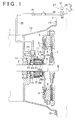
- FIG. 1 is an enlarged cross-sectional view illustrating a connection of a transmission and an engine of a motor vehicle having a clutch operated by a cylinder mechanism in accordance with an embodiment of the present invention;
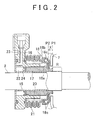
- FIG. 2 is an enlarged cross-sectional view illustrating an area around a piston in the cylinder mechanism;
- FIG. 3 is an enlarged cross-sectional view illustrating an area around the piston in the cylinder mechanism;
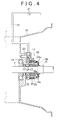
- FIG. 4 is a cross-sectional view illustrating an area around the cylinder mechanism when the transmission is removed from the motor vehicle;
- FIG. 5 is an enlarged cross-sectional view illustrating the area around the piston in the cylinder mechanism; and
- FIG. 6 is a schematic view illustrating an area around an open-shut valve in the case in which the open-shut valve is opened and shut through an operational control of an electronic control unit.
- Hereinafter, an embodiment of a cylinder mechanism used to drive the clutch in an automobile in accordance with the present invention will be described with reference to FIGS. 1 to 5. In the automobile, the clutch is installed between an engine and a transmission, and is operated to connect or disconnect the engine and the transmission. As illustrated in FIG. 1, the clutch includes a
clutch plate 3 connected to aninput shaft 2 of the transmission 1 and thus integrally rotates with theinput shaft 2, as well as aclutch cover 4, which is connected to an output shaft (not shown) of theengine 5 and thus is integrally rotated with the output shaft. Theclutch plate 3 and theclutch cover 4 are arranged on a same axis as theinput shaft 2 of the transmission 1. Theinput shaft 2 passes through theclutch plate 3 such that it can be separated from theclutch plate 3 in an axial direction. - The
clutch cover 4 supports adiaphragm spring 7, to which anengagement member 6 that engages theclutch plate 3, is attached. Thediaphragm spring 7 functions as a lever that biases theengagement member 6 in an engagement direction (toward the right side in FIG. 1) to press theengagement member 6 against theclutch plate 3. More specifically, thediaphragm spring 7 may be a coned disc spring that biases theengagement member 6 in the engagement direction. - The
engagement member 6 is attached to a portion of thediaphragm spring 7 that is located farthest from the input shaft 2 (hereinafter "peripheral portion of the diaphragm spring"). Further, in thediaphragm spring 7, an intermediate portion, between the portion nearest to theinput shaft 2 and the peripheral portion of thediaphragm spring 7, is in contact with afulcrum 8 of theclutch cover 4. When the portion of thediaphragm spring 7 located nearest to the input shaft 2 (hereinafter "central portion of the diaphragm spring") is pressed toward theclutch plate 3, thediaphragm spring 7 is displaced in a releasing direction, i.e., a counter clockwise direction about thefulcrum 8, that is opposite engagement direction, so that theengagement member 6 moves away from theclutch plate 3. - When the central portion of the
diaphragm spring 7 is not pressed toward theclutch plate 3, theengagement member 6 is pushed in the engagement direction by the biasing force of thediaphragm spring 7, thereby pressing theengagement member 6 against theclutch plate 3. As a result, theengagement member 6 engages theclutch plate 3. At this time, theengine 5 is connected with the transmission 1 via the clutch, so that rotational force may be transmitted between theengine 5 and the transmission 1. - In contrast, when the central portion of the
diaphragm spring 7 is pressed toward theclutch plate 3, thediaphragm spring 7 is displaced in the release direction, and thus theengagement member 6 moves away from theclutch plate 3. As a result, theengagement member 6 disengages theclutch plate 3. At this time, theengine 5 is disconnected from the transmission 1, so that rotational force cannot be transmitted between theengine 5 and the transmission 1. - Next, a
cylinder mechanism 11 that manipulates thediaphragm spring 7 in order to connect and disconnect the clutch will be described. Thiscylinder mechanism 11 is attached to aclutch housing 12. Theclutch housing 12 is fixed to theengine 5 and to the transmission 1 using, for instance,bolts 13. Further, theclutch housing 12 is provided with abearing 14 that rotatably supports theinput shaft 2 of the transmission 1. Theinput shaft 2 of the transmission 1 passes through thecylinder mechanism 11 attached to theclutch housing 12. - The
cylinder mechanism 11 includes a cylindricalinner body 15, which is fixed to theclutch housing 12 and extends along the same axis as theinput shaft 2; anouter body 16, which is also fixed to theclutch housing 12 and is located on the same axis as theinput shaft 2, that surrounds the outer perimeter of theinner body 15; and acylindrical piston 17, which is installed between theinner body 15 and theouter body 16. - The
piston 17 slides on the outer peripheral surface of theinner body 15 in the direction of the central line of theinner body 15. The end portion of thepiston 17 that faces thediaphragm spring 7 is exposed from a right end of theouter body 16 toward thediaphragm spring 7. Aninner race 18a of abearing 18 is fixedly fitted around the end of thepiston 17. Between theinner race 18a of thebearing 18 and theouter body 16, aspring 20 that presses thebearing 18 and thepiston 17 against thediaphragm spring 7 is installed together with a cylindrical bellows 21, which surrounds the outer side of thespring 20 in the circumferential direction of theinput shaft 2. The bellows 21 prevents dust from entering thepiston 17, and can expand or contract in the axial direction of theinput shaft 2. Both ends of thebellows 21, lined along axial direction of theinput shaft 2, are fixed to theouter body 16 and theinner race 18a, respectively. - The
piston 17 is biased toward a reference position, i.e. a position where thepiston 17 contacts the central portion of the diaphragm spring 7 (to be precise, the portion at which thebearing 18 comes in contact with the portion of the diaphragm spring 7) by thespring 20. Further, when thepiston 17 is pressed at the reference position by thespring 20, anouter race 18b of thebearing 18 is pressed to the portion of thediaphragm spring 7 that is nearest to theinput shaft 2 by the biasing force of thespring 20. In this state, when theclutch cover 4 and thediaphragm spring 7 are rotated in conjunction with the rotation of theengine 5, theouter race 18b of thebearing 18, which is pressed to the portion of thediaphragm spring 7 by the biasing force of thespring 20, is rotated together with thediaphragm spring 7, and thusballs 18c located between the inner andouter races bearing 18 are made to rotate. - Further, when the
diaphragm spring 7 and theouter race 18b rotate, thespring 20 serves to prevent abnormal sounds from being made by relative displacement between thediaphragm spring 7 and theouter race 18b in the rotational direction. In other words, the magnitude of the biasing force of thespring 20 is preset such that there is no relative displacement generated along the rotational direction between thediaphragm spring 7 and theouter race 18b when thediaphragm spring 7 is rotated. - A
pressure chamber 22 filled with oil as working oil is formed at a portion of thecylinder mechanism 11 that is surrounded by theinner body 15, theouter body 16 and thepiston 17, i.e. which being adjacent to one end of thepiston 17, the other end of which is located on the side of thediaphragm spring 7. Thepressure chamber 22 is connected with anoil passage 23 formed in theouter body 16. Further, at one end of thepiston 17, which is located on the side of thepressure chamber 22, there is fixed acup 24 that acts as a seal preventing oil leakage between the outer circumferential surface of theinner body 15 and the inner circumferential surface of thepiston 17 and between the inner circumferential surface of theouter body 16 and the outer circumferential surface of thepiston 17 in thepressure chamber 22. - The
pressure chamber 22 is supplied with oil, so that the oil in thepressure chamber 22 is pressurized. When the pressure in thepressure chamber 22 is increased, thepiston 17 is displaced from a reference position toward thediaphragm spring 7 by the force derived from the increased pressure, thereby pressing the central portion of thediaphragm spring 7. Thus, thediaphragm spring 7 is displaced in a release direction, and theengagement member 6 moves away from theclutch plate 3. Accordingly, the clutch is thereby disengaged. - Further, when the pressure inside the
pressure chamber 22 is decreased by decompressing the oil in thepressure chamber 22, the pressure acting on thediaphragm spring 7 by thepiston 17 also decreases. For this reason, thediaphragm spring 7 is displaced in the engagement direction by the biasing force thereof, and thus the biasing force causes theengagement member 6 to make a close contact with theclutch plate 3. Accordingly, the clutch is thereby engaged. At this time, thepiston 17 moves in a direction opposite to the engagement direction when thediaphragm spring 7 is displaced in the engagement direction, thereby returning the piston to the reference position. - Next, the structure in which the
piston 17 of thecylinder mechanism 11 is displaced in a direction toward thediaphragm spring 7 or opposite thereto will be described, that is, along a central axis of theinner body 15 by pressurizing or decompressing the oil in thepressure chamber 22. - In the
cylinder mechanism 11, theoil passage 23 of theouter body 16 is connected with anoil pipe 25, which supplies the oil to thepressure chamber 22 via theoil passage 23. Theoil pipe 25 is extended through the out side of theclutch housing 12. Further, a portion of theoil pipe 25 that extends to the outside of theclutch housing 12 is provided with a bleeder 26 for discharging the air. Further, a part of theoil pipe 25, which is located on the upstream side of the bleeder 26, is connected to a pressurizingunit 27 for pressing the oil in thepressure chamber 22 of thecylinder mechanism 11. - The pressurizing
unit 27 includes acylinder 28 to which theoil pipe 25 is connected, apiston 30 that reciprocates in thecylinder 28 in response to the operation of aclutch pedal 29, and areserve tank 31, which is connected to thecylinder 28, that supplies a complementing amount of oil when an insufficient amount of oil is supplied and receiving surplus amount of oil when oil is oversupplied. Further, in the pressurizingunit 27, a neutral position of theclutch pedal 29 may be adjusted by a pedal adjustment screw, and a neutral position of thepiston 30 may be adjusted by a piston adjustment screw. - In the pressurizing
unit 27, the oil in thecylinder 28 is delivered to theoil pipe 25 by the movement of thepiston 30 when aclutch pedal 29 is depressed. Accordingly, the oil in thepressure chamber 22 of thecylinder mechanism 11 is pressurized so that when thepiston 17 moves from the reference position P2 towards thediaphragm spring 7, the capacity of thepressure chamber 22 is increased, and the oil flows into thepressure chamber 22 through theoil passage 23 and theoil pipe 25. The movement of thepiston 17 causes thepiston 17 to press the central portion of thediaphragm spring 7. As a result, thediaphragm spring 7 is displaced in a release direction, and theengagement member 6 moves away from theclutch plate 3. Thereby, theengagement member 6 is disengaged from theclutch plate 3. FIG. 2 is an enlarged view illustrating the position (i.e. a position P1 in the drawing) of thepiston 17 with respect to the central line of theinner body 15 in thecylinder mechanism 11 in the released state. - Further, when the
clutch pedal 29 of FIG. 1 is released, theclutch pedal 29 returns to its original position due to the biasing force of a return spring (not shown), and the resultant movement of thepiston 30 of the pressurizingunit 27 causes the oil in theoil pipe 25 to be drawn into thecylinder 28. Accordingly, the oil in thepressure chamber 22 of thecylinder mechanism 11 is depressurized, and thus the pressing of thepiston 17 of thecylinder mechanism 11 against thediaphragm spring 7 is released. As a result, thediaphragm spring 7 is displaced in the engagement direction on the basis of the biasing force of thediaphragm spring 7, and theengagement member 6 is pressed against theclutch plate 3. Thus, theengagement member 6 engages theclutch plate 3. At this time, when thediaphragm spring 7 is displaced in the engagement direction, thepiston 17 is displaced in the direction in which the capacity of thepressure chamber 22 is reduced. Thus, the oil in thepressure chamber 22 flows to theoil passage 23 and theoil pipe 25. - Further, the displacement of the
diaphragm spring 7 in the engagement direction causes thepiston 17 to move from the position P1 indicated in FIG. 2 by a distance X in the direction in which the capacity of thepressure chamber 22 is reduced, thereby returning thepiston 17 to the reference position P2. Thus, when theclutch pedal 29 is operated to release or engage the clutch, the range in which thepiston 17 of thecylinder mechanism 11 is displaced along the central line of theinner body 15 is between the reference position P2 to the position P1 in the drawing. Accordingly, the portion of the outer peripheral surface of theinner body 15 lying toward thediaphragm spring 7 from the position (position P1) that is nearest to thediaphragm spring 7 is always exposed to the outside. For this reason, this portion (hereinafter, referred to as "exposed portion R") cannot avoid being contaminated with foreign material such as dust. - The movement range of the
piston 17 is shifted to the side (left side in FIG. 2) of the transmission 1 as theengagement member 6 of FIG. 1 becomes worn in the clutch. This is because, as theengagement member 6 becomes worn, the portion of thediaphragm spring 7 that is nearest to theinput shaft 2 is displaced in a clockwise direction about thefulcrum 8. In this manner, when the movement range of thepiston 17 is shifted to left in FIG. 2 by the increase of the abrasion of theengagement member 6, the exposed portion R of theinner body 15 expands to the left in the drawing. - Next, the movement of the
piston 17 of thecylinder mechanism 11 when the transmission 1 is removed from the motor vehicle will be described. When the transmission 1 shown in FIG. 1 is removed from the motor vehicle, the following operations [1] through [3] are sequentially carried out. [1] A portion of theoil pipe 25, which is located on the downstream side of the bleeder 26, i.e. on the side of thecylinder mechanism 11, is separated from the bleeder 26, thereby separating the pressurizingunit 27 and thecylinder mechanism 11. [2] Thebolts 13 fixing theclutch housing 12 to theengine 5 are separated. [3] The entire transmission 1 is moved in a direction separating it from theengine 5, i.e. in the left-hand direction in the drawing, thereby pulling theinput shaft 2 of the transmission 1 out of theclutch plate 3 while separating thecylinder mechanism 11 from thediaphragm spring 7. By performing operations [1] through [3] in sequence, the transmission 1 is removed from theengine 5 together with thecylinder mechanism 11, as illustrated in FIG. 4, and thus is removed from the motor vehicle. - When the transmission 1 is mounted in the motor vehicle (FIG. 1), the piston 17 (particularly, the bearing 18) of the
cylinder mechanism 11 is in contact with thediaphragm spring 7 due to the biasing force of thespring 20. In contrast, when the transmission 1 is removed from the motor vehicle, thepiston 17 of thecylinder mechanism 11 is not in contact with thediaphragm spring 7. As such, thepiston 17 is pressed in the direction (right-hand direction of FIG. 1) in which the capacity of thepressure chamber 22 is increased by the biasing force of thespring 20. Because the portion of theoil pipe 25 that is separated from the bleeder 26 is exposed to atmospheric pressure and thepiston 17 is pressed by the biasing force of thespring 20, as described above, the oil existing in theoil pipe 25 and theoil passage 23 flows into thepressure chamber 22, thereby thepiston 17 moves in the right-hand direction in the drawing. As a result, as illustrated in FIG. 3, thepiston 17 is displaced from the position P1, which is nearest to the exposed portion R in the normal movement range (from P2 to P1) of thepiston 17, toward the the exposed portion R (the side of thediaphragm spring 7 in FIG. 1). - Here, the inconvenience caused by the displacement of the
piston 17 is described. The foreign material such as dust settles on the exposed portion R of theinner body 15, as described above. For this reason, when thepiston 17 is displaced towards the exposed portion R, the foreign material becomes stuck between thepiston 17 and theinner body 15, which interferes with the movement of thepiston 17. If the transmission 1 is mounted in the motor vehicle again in this state, an attempt to move thepiston 17 to displace thediaphragm spring 7 in the release direction may be unsuccessful. Consequently, the reliability when operating the clutch is deteriorated. Further, when the engagement member 6 (FIG. 1) of the clutch is worn and thus the exposed portion R extends in the left-hand direction of FIG. 3, the accumulated foreign materials stuck may reach thecup 24. Thus, the ability to seal thepressure chamber 22 by the aid of thecup 24 may be reduced by the hindrance in the movement of thepiston 17 due to the engagement of the foreign materials. - In order to cope with this inconvenience, in this embodiment, as illustrated in FIG. 1, the portion of the
oil pipe 25 that is located downstream of the bleeder 26 and is exposed to the outside of theclutch housing 12 is provided with an open-shutvalve 41 for regulating the flow of the oil. When opened, the open-shutvalve 41 allows the flow of the oil, thereby enabling the oil to flow into and out of thepressure chamber 22 of thecylinder mechanism 11. However, when it is shut, the open-shutvalve 41 prevents the flow of the oil, thereby preventing the oil from flowing into or out of thepressure chamber 22. - When the transmission is removed from the motor vehicle, the following operations are sequentially carried out before the work [1] is performed. In the pressurizing
unit 27, thepiston 30 in thecylinder 28 is displaced in a direction away from theoil pipe 25 by manipulating the pedal adjustment screw or the piston adjustment screw, and the oil is drawn from theoil pipe 25 into thecylinder 28. Thus, the oil in thepressure chamber 22 of thecylinder mechanism 11 is drawn toward theoil passage 23 and theoil pipe 25. - The open-shut
valve 41 is shut manually. Thus, the oil is prevented from flowing into and out of thepressure chamber 22 of thecylinder mechanism 11. By shutting the open-shutvalve 41, theoil pipe 25 connected to theoil passage 23 of thecylinder mechanism 11 is no longer exposed to the atmospheric pressure when the transmission is removed from the motor vehicle by subsequently carrying out the operations [1] through [3]. - Hence, after the transmission 1 is removed, the
piston 17 of thecylinder mechanism 11 is pressed in the direction (toward the right in FIG. 1) in which the capacity of thepressure chamber 22 is increased by the biasing force of thespring 20. Even in this case, the oil present in theoil pipe 25 and theoil passage 23 does not flow into thepressure chamber 22, thereby preventing thepiston 17 from moving in the right-hand direction in the drawing. Accordingly, as illustrated in FIG. 5, the position of thepiston 17 is maintained at a position (reference position P2 in the example of FIG. 5) within the normal movement range (between P2 and P1), so that thepiston 17 does not move into the exposed portion R. For this reason, the inconvenience due to the accumulation of the foreign material attached to the exposed portion R between thepiston 17 and theinner body 15 are avoided. - In the embodiment as described above, the following effects are obtained. (1) When the transmission 1 is removed from the motor vehicle, the
cylinder mechanism 11 is separated from the side of thediaphragm spring 7 in the clutch in the state in which the open-shutvalve 41 is shut. At this time, because the oil is prevented from flowing into or out of thepressure chamber 22 of thecylinder mechanism 11 when the open-shutvalve 41 is shut, thepiston 17 of thecylinder mechanism 11 is prevented from moving in the direction in which the capacity of thepressure chamber 22 is increased toward thediaphragm spring 7, even when it is pressed in the capacity-increasing direction by thespring 20. Thus, thepiston 17 is maintained within the normal movement range (between P2 and P1) by shutting the open-shutvalve 41. As such, thepiston 17 is prevented from moving beyond the normal movement range into the exposed portion R, so that the foreign material present on the exposed portion R is reliably prevented from becoming trapped between thepiston 17 and theinner body 15 by the movement of thepiston 17. - (2) When the transmission 1 is removed from the motor vehicle, the open-shut
valve 41 is shut in the state in which the oil is drawn into thecylinder 28 from theoil pipe 25 by displacement of thepiston 30 of the pressurizingunit 27 in a direction away from theoil pipe 25 through the manipulation of the pedal or piston adjustment screw of the pressurizingunit 27. Here, when thecylinder mechanism 11 is separated from the side of thediaphragm spring 7 by shutting the open-shutvalve 41, thepiston 17 of thecylinder mechanism 11 is pressed in the direction in which the capacity of thepressure chamber 22 is increased by the biasing force of thespring 20. Thereby, the oil in thepressure chamber 22 and so forth expands, so that thepiston 17 can move in the capacity-increasing direction to some extent. However, as described above, the shutting of the open-shutvalve 41 limits movement of thepiston 17 to within the normal movement range, even when thepiston 17 moves to some extent in the direction in which the capacity of thepressure chamber 22 is increased by the biasing force of thespring 20. - (3) The open-shut
valve 41 is attached to a portion of theoil pipe 25 that extends outside theclutch housing 12. Thus, the open-shutvalve 41 is easily manipulated manually, so that it is possible to improve the manipulation of the open-shutvalve 41. - Further, the embodiment may be modified, for example, as follows. The open-shut
valve 41 may be automatically opened and shut through an operational control of anelectronic control unit 42, as illustrated in FIG. 6 by employing an electromagnetic valve as the open-shutvalve 41. In this case, theelectronic control unit 42 determines whether the motor vehicle is driven based on an off signal from theignition switch 43, and then controls the opening and shutting of the open-shutvalve 41 in accordance with the determination. More specifically, if it is determined that there is no off signal from theignition switch 43 and that the motor vehicle is operating, the open-shutvalve 41 is opened. If it is determined that there is an off signal from theignition switch 43 and that the motor vehicle is not operating, the open-shutvalve 41 is shut. Here, if the open-shutvalve 41 is shut when the motor vehicle is operating and thus thepiston 17 of thecylinder mechanism 11 is prevented from moving, this may interfere with the operation of the clutch by thecylinder mechanism 11. However, as described above, by controlling the opening and shutting of the open-shutvalve 41, the open-shutvalve 41 is prevented from being shut while the motor vehicle is operating, and thus is open, so that thepiston 17 is prevented from stopping during the operation of the motor vehicle, and thus avoids interfering with the driving of the clutch. - The position at which the open-shut
valve 41 is installed may be modified as appropriate. The open-shutvalve 41 may be attached as close to thepressure chamber 22 of thecylinder mechanism 11 as possible, to minimize the amount of the oil sealed by thepressure chamber 22 and the resultant expansion of the oil when the open-shutvalve 41 is shut. Further, as described above, if theelectronic control unit 42 controls the operation of the open-shutvalve 41, a worker does not need to manually open or shut the open-shutvalve 41. Hence, the open-shutvalve 41 is installed in theclutch housing 12, and may be installed at a position closer to thepressure chamber 22. - An oil pump for drawing the oil from the
pressure chamber 22 may be provided in place of the open-shutvalve 41. When theoil pipe 25 is separated from the bleeder 26, the pressure in thepressure chamber 22 is controlled through the operational control of the oil pump by the electronic control unit. Thereby, the displacement toward the exposed portion R of thepiston 17 in thecylinder mechanism 11 may be regulated. In this case, the force acting on thepiston 17 due to the pressure in thepressure chamber 22 acts in the direction opposite to the biasing force of thespring 20. Thus, the operation of the oil pump is controlled such that the force acting on thepiston 17 due to the pressure in thepressure chamber 22 is equal to or greater than the biasing force of thespring 20, so that the displacement toward the exposed portion R of thepiston 17 is limited. Further, if the force acting on thepiston 17 due to the pressure in thepressure chamber 22 is equal to the biasing force of thespring 20, thepiston 17 is maintained at a predetermined position within the normal movement range (between P2 and P1). Further, if the force acting on thepiston 17 due to the pressure in thepressure chamber 22 is greater than the biasing force of thespring 20, thepiston 17 is pulled to a position in the direction in which the capacity of thepressure chamber 22 is reduced, beyond the reference position P2. With this configuration, the oil pump and the electronic control unit function as regulating means for limiting the movement of the piston towards the exposed portion R of thepiston 17. - In place of the
diaphragm spring 7, a lever biased in the engagement direction by a separate spring may be employed. The lever may press theengagement member 6 against theclutch plate 3. - The
piston 17 may be fixed at a position within its normal movement range by using a jig that fixes the position of thepiston 17. In this case, the jig functions as regulating means for limiting the movement towards the exposed portion R of thepiston 17. - While the invention has been shown and described with respect to the example embodiments, it will be understood by those skilled in the art that various changes and modifications may be made without departing from the scope of the invention.
Claims (8)
- A cylinder mechanism (11), which manipulates a lever (7) that is biased in an engagement direction to press an engagement member (6) against a clutch plate (3) and that maintains an engaged state between the clutch plate (3) and the engagement member (6), the cylinder mechanism (11) includes: a piston (17) that is movable toward and away from the lever (7) by sliding on the outer peripheral surface of a shaft member (15), which is located on the same axis as the clutch plate (3), in an axial direction; a spring (20) that biases a pressing member of the piston (17) toward a reference position at which the pressing member contacts the lever (7); and movement means (27) for moving the piston (17) from the reference position toward the lever (7), wherein, when the lever (7) is displaced to release the clutch plate (3) and the engagement member (6) by the movement of the piston (17), caused by the movement means (27), the cylinder mechanism (11) characterized by comprising:regulating means (41, 42) for preventing the piston (17) from moving further toward the lever (7) from a position nearest to the lever (7) within a normal movement range of the piston 17.
- The cylinder mechanism of claim 1, wherein the piston (17) has a cylindrical shape and is fitted around the outer peripheral surface of the shaft member (15), and is inserted inside a cylindrical outer body (16) located coaxially with the shaft member (15); the movement means (27) moves the piston (17) toward the lever (7) by supplying working oil to a pressure chamber (22), provided at an end side of the piston (17) opposite the lever side of the piston (17), defined by the shaft member (15), the piston (17) and the outer body (16); and the regulating means (41, 42) controls the pressure in the pressure chamber (22) such that force acting on the piston (17) due to the pressure in the pressure chamber (22) acts in a direction opposite that of a biasing force of the spring (20) and is greater than the biasing force.
- The cylinder mechanism of claim 1, wherein the piston (17) has a cylindrical shape and is fitted around the outer peripheral surface of the shaft member (15), and is inserted inside a cylindrical outer body (16) located coaxially with the shaft member (15); the movement means (27) moves the piston (17) toward the lever (7) by supplying working oil to a pressure chamber (22), provided at an end side of the piston (17) opposite the lever side of the piston (17), defined by the shaft member (15), the piston (17) and the outer body (16); and the regulating means (41, 42) prevents working oil from flowing into and out of the pressure chamber (22).
- The cylinder mechanism of claim 3, wherein the regulating means (41, 42) includes an open-shut valve (41) that is provided on a hydraulic pipe (25) connected to the pressure chamber (22), wherein the hydraulic pipe (25) supplies and discharges the working oil with respect to the pressure chamber (22).
- The cylinder mechanism of claim 4, wherein the open-shut valve (41) is provided outside a clutch housing (12).
- The cylinder mechanism of claim 1 or 2, wherein the regulating means includes a pump for drawing the oil from the pressure chamber (22).
- The cylinder mechanism of any one of claims 1 to 6, wherein the regulating means (41, 42) includes an electronic control unit (42) that controls the operation of the regulating means (41) in accordance with an operation state of a motor vehicle; and the electronic control unit (42) prevents the operation of the regulating means (41) when the motor vehicle is being operated and permits the operation of the regulating means (41) when the motor vehicle is not being operated.
- The cylinder mechanism of claim 7, wherein the regulating means (41, 42) is provided in a clutch housing (12).
Applications Claiming Priority (1)
| Application Number | Priority Date | Filing Date | Title |
|---|---|---|---|
| JP2006307917A JP4367478B2 (en) | 2006-11-14 | 2006-11-14 | Cylinder device |
Publications (3)
| Publication Number | Publication Date |
|---|---|
| EP1939482A2 true EP1939482A2 (en) | 2008-07-02 |
| EP1939482A3 EP1939482A3 (en) | 2010-03-24 |
| EP1939482B1 EP1939482B1 (en) | 2018-08-29 |
Family
ID=39367674
Family Applications (1)
| Application Number | Title | Priority Date | Filing Date |
|---|---|---|---|
| EP07254432.3A Ceased EP1939482B1 (en) | 2006-11-14 | 2007-11-12 | Cylinder mechanism |
Country Status (2)
| Country | Link |
|---|---|
| EP (1) | EP1939482B1 (en) |
| JP (1) | JP4367478B2 (en) |
Families Citing this family (1)
| Publication number | Priority date | Publication date | Assignee | Title |
|---|---|---|---|---|
| KR101953719B1 (en) * | 2017-12-22 | 2019-03-05 | 주식회사 인팩 | Multi-plate clutch operating device of electric drive system |
Citations (1)
| Publication number | Priority date | Publication date | Assignee | Title |
|---|---|---|---|---|
| JP2002349601A (en) | 2001-05-30 | 2002-12-04 | Nissin Kogyo Co Ltd | Vehicle clutch slave cylinder |
Family Cites Families (3)
| Publication number | Priority date | Publication date | Assignee | Title |
|---|---|---|---|---|
| ITTO980578A1 (en) * | 1998-07-02 | 2000-01-02 | C R F Societa Consotile Per Az | CONTROL SYSTEM OF A CLUTCH COUPLING FOR MOTOR VEHICLES |
| DE10018649A1 (en) * | 2000-04-14 | 2001-10-25 | Mannesmann Sachs Ag | Actuator for frictional coupling has control/regulating valve for controling cylinder device depending on actual/desired disengagement, control electronics with various characteristics |
| FR2895477B1 (en) * | 2005-12-23 | 2009-05-22 | Renault Sas | AUTOMATICALLY CONTROLLED FRICTION CLUTCH |
-
2006
- 2006-11-14 JP JP2006307917A patent/JP4367478B2/en not_active Expired - Fee Related
-
2007
- 2007-11-12 EP EP07254432.3A patent/EP1939482B1/en not_active Ceased
Patent Citations (1)
| Publication number | Priority date | Publication date | Assignee | Title |
|---|---|---|---|---|
| JP2002349601A (en) | 2001-05-30 | 2002-12-04 | Nissin Kogyo Co Ltd | Vehicle clutch slave cylinder |
Also Published As
| Publication number | Publication date |
|---|---|
| EP1939482A3 (en) | 2010-03-24 |
| EP1939482B1 (en) | 2018-08-29 |
| JP4367478B2 (en) | 2009-11-18 |
| JP2008121818A (en) | 2008-05-29 |
Similar Documents
| Publication | Publication Date | Title |
|---|---|---|
| EP2187105B1 (en) | Suck-back valve | |
| WO2006051591A1 (en) | Safety valve device | |
| EP1978271B1 (en) | Bleeder device | |
| EP1939482B1 (en) | Cylinder mechanism | |
| JP2744829B2 (en) | Apparatus for controlling a hydraulically actuated friction disc clutch having a diaphragm spring | |
| JP2001193763A (en) | Operating device for operation of friction clutches, especially for operation by pneumatic action | |
| US7341137B2 (en) | Clutch assembly | |
| US6167995B1 (en) | Release mechanism for a motor vehicle friction clutch | |
| US4658850A (en) | Flow control valve with switching valve | |
| KR100470620B1 (en) | Automotive clutch control device | |
| EP1841979B1 (en) | Actuator for a vehicle clutch | |
| US8083044B2 (en) | Clutch actuator and method for actuating a clutch | |
| JPH09269019A (en) | Vehicle auto clutch device | |
| JP2005325879A (en) | Hydraulic control device for automatic transmission | |
| JP3869143B2 (en) | Automotive clutch device | |
| CN101287915B (en) | Servo valve for power pedal operation | |
| JP3942089B2 (en) | Clutch control system | |
| CN113898550A (en) | Valve unit, power control system and axial piston machine having such a power control system | |
| JPS5965625A (en) | Control method for clutch | |
| EP0982510B1 (en) | System for controlling a friction coupling for motor-vehicles | |
| JP4115230B2 (en) | Clutch booster | |
| JPH09269021A (en) | Auto clutch device for automobile | |
| JP4385179B2 (en) | Electronically controlled throttle device | |
| KR100911549B1 (en) | Automotive Clutch Booster | |
| JPH09269020A (en) | Vehicle auto clutch device |
Legal Events
| Date | Code | Title | Description |
|---|---|---|---|
| PUAI | Public reference made under article 153(3) epc to a published international application that has entered the european phase |
Free format text: ORIGINAL CODE: 0009012 |
|
| 17P | Request for examination filed |
Effective date: 20071122 |
|
| AK | Designated contracting states |
Kind code of ref document: A2 Designated state(s): AT BE BG CH CY CZ DE DK EE ES FI FR GB GR HU IE IS IT LI LT LU LV MC MT NL PL PT RO SE SI SK TR |
|
| AX | Request for extension of the european patent |
Extension state: AL BA HR MK RS |
|
| PUAL | Search report despatched |
Free format text: ORIGINAL CODE: 0009013 |
|
| AK | Designated contracting states |
Kind code of ref document: A3 Designated state(s): AT BE BG CH CY CZ DE DK EE ES FI FR GB GR HU IE IS IT LI LT LU LV MC MT NL PL PT RO SE SI SK TR |
|
| AX | Request for extension of the european patent |
Extension state: AL BA HR MK RS |
|
| RIC1 | Information provided on ipc code assigned before grant |
Ipc: F16D 25/08 20060101AFI20100218BHEP Ipc: F16D 48/06 20060101ALI20100218BHEP |
|
| AKX | Designation fees paid |
Designated state(s): DE FR GB IT |
|
| RAP1 | Party data changed (applicant data changed or rights of an application transferred) |
Owner name: TOYOTA JIDOSHA KABUSHIKI KAISHA |
|
| STAA | Information on the status of an ep patent application or granted ep patent |
Free format text: STATUS: EXAMINATION IS IN PROGRESS |
|
| 17Q | First examination report despatched |
Effective date: 20170807 |
|
| GRAP | Despatch of communication of intention to grant a patent |
Free format text: ORIGINAL CODE: EPIDOSNIGR1 |
|
| STAA | Information on the status of an ep patent application or granted ep patent |
Free format text: STATUS: GRANT OF PATENT IS INTENDED |
|
| INTG | Intention to grant announced |
Effective date: 20180322 |
|
| GRAS | Grant fee paid |
Free format text: ORIGINAL CODE: EPIDOSNIGR3 |
|
| GRAA | (expected) grant |
Free format text: ORIGINAL CODE: 0009210 |
|
| STAA | Information on the status of an ep patent application or granted ep patent |
Free format text: STATUS: THE PATENT HAS BEEN GRANTED |
|
| AK | Designated contracting states |
Kind code of ref document: B1 Designated state(s): DE FR GB IT |
|
| REG | Reference to a national code |
Ref country code: GB Ref legal event code: FG4D |
|
| REG | Reference to a national code |
Ref country code: DE Ref legal event code: R096 Ref document number: 602007055925 Country of ref document: DE |
|
| REG | Reference to a national code |
Ref country code: FR Ref legal event code: PLFP Year of fee payment: 12 |
|
| REG | Reference to a national code |
Ref country code: DE Ref legal event code: R084 Ref document number: 602007055925 Country of ref document: DE |
|
| REG | Reference to a national code |
Ref country code: GB Ref legal event code: 746 Effective date: 20181228 |
|
| PGFP | Annual fee paid to national office [announced via postgrant information from national office to epo] |
Ref country code: DE Payment date: 20181030 Year of fee payment: 12 |
|
| PGFP | Annual fee paid to national office [announced via postgrant information from national office to epo] |
Ref country code: IT Payment date: 20181122 Year of fee payment: 12 Ref country code: GB Payment date: 20181107 Year of fee payment: 12 Ref country code: FR Payment date: 20181011 Year of fee payment: 12 |
|
| REG | Reference to a national code |
Ref country code: DE Ref legal event code: R097 Ref document number: 602007055925 Country of ref document: DE |
|
| PLBE | No opposition filed within time limit |
Free format text: ORIGINAL CODE: 0009261 |
|
| STAA | Information on the status of an ep patent application or granted ep patent |
Free format text: STATUS: NO OPPOSITION FILED WITHIN TIME LIMIT |
|
| 26N | No opposition filed |
Effective date: 20190531 |
|
| REG | Reference to a national code |
Ref country code: DE Ref legal event code: R119 Ref document number: 602007055925 Country of ref document: DE |
|
| GBPC | Gb: european patent ceased through non-payment of renewal fee |
Effective date: 20191112 |
|
| PG25 | Lapsed in a contracting state [announced via postgrant information from national office to epo] |
Ref country code: FR Free format text: LAPSE BECAUSE OF NON-PAYMENT OF DUE FEES Effective date: 20191130 Ref country code: DE Free format text: LAPSE BECAUSE OF NON-PAYMENT OF DUE FEES Effective date: 20200603 Ref country code: IT Free format text: LAPSE BECAUSE OF NON-PAYMENT OF DUE FEES Effective date: 20191112 Ref country code: GB Free format text: LAPSE BECAUSE OF NON-PAYMENT OF DUE FEES Effective date: 20191112 |