EP1939468A1 - Fixing knob - Google Patents
Fixing knob Download PDFInfo
- Publication number
- EP1939468A1 EP1939468A1 EP07380390A EP07380390A EP1939468A1 EP 1939468 A1 EP1939468 A1 EP 1939468A1 EP 07380390 A EP07380390 A EP 07380390A EP 07380390 A EP07380390 A EP 07380390A EP 1939468 A1 EP1939468 A1 EP 1939468A1
- Authority
- EP
- European Patent Office
- Prior art keywords
- nut
- arms
- knob
- casing
- rod
- Prior art date
- Legal status (The legal status is an assumption and is not a legal conclusion. Google has not performed a legal analysis and makes no representation as to the accuracy of the status listed.)
- Granted
Links
Images
Classifications
-
- G—PHYSICS
- G05—CONTROLLING; REGULATING
- G05G—CONTROL DEVICES OR SYSTEMS INSOFAR AS CHARACTERISED BY MECHANICAL FEATURES ONLY
- G05G1/00—Controlling members, e.g. knobs or handles; Assemblies or arrangements thereof; Indicating position of controlling members
- G05G1/08—Controlling members for hand actuation by rotary movement, e.g. hand wheels
- G05G1/10—Details, e.g. of discs, knobs, wheels or handles
- G05G1/12—Means for securing the members on rotatable spindles or the like
-
- F—MECHANICAL ENGINEERING; LIGHTING; HEATING; WEAPONS; BLASTING
- F16—ENGINEERING ELEMENTS AND UNITS; GENERAL MEASURES FOR PRODUCING AND MAINTAINING EFFECTIVE FUNCTIONING OF MACHINES OR INSTALLATIONS; THERMAL INSULATION IN GENERAL
- F16B—DEVICES FOR FASTENING OR SECURING CONSTRUCTIONAL ELEMENTS OR MACHINE PARTS TOGETHER, e.g. NAILS, BOLTS, CIRCLIPS, CLAMPS, CLIPS OR WEDGES; JOINTS OR JOINTING
- F16B37/00—Nuts or like thread-engaging members
- F16B37/16—Wing-nuts
Definitions
- the present invention relates to a fixing knob used as a connecting part, being formed by a nut and a casing giving it a greater volume to make its actuation easier, especially with an auxiliary rod, for example with the rod of a screwdriver.
- the knob of the invention can be used as a fixing or connecting means identical to that of a normal nut but with the advantage of having means which make its actuation easier, having special application in the automotive industry.
- the nuts used for connecting or fixing parts consist of a core generally in the form of a square or straight hexagonal part provided with a threaded axial through borehole. In order to tighten or loosen these nuts it is necessary to have a suitable wrench, a tool which is not always available.
- This situation can present itself when having to tighten or loosen certain nuts of a vehicle, the tool supply of which does not usually include a wrench.
- the object of the present invention is to eliminate the problems set forth by means of a fixing knob including a nut and having means that make the actuation of said nut with the hand easier and the necessary tightening thereof can be carried out with a rod, for example with the rod of a screwdriver, a tool which does traditionally enter into the tool supply of an automobile
- the knob of the invention is formed by a nut and an actuation casing.
- the nut can be of a square or hexagonal base.
- the casing forming part of the knob of the invention comprises a disk which is fixed in a position centered at one of the bases of the nut perpendicular to such nut, said base having a hole which is an extension of the threaded borehole of the nut.
- the casing also includes at least two arms radially arranged around the nut fixed to the disk. These arms have a passage through which an actuation rod can be introduced.
- the casing can include only two diametrically opposite or three angularly equidistant radial arms. Furthermore the arms can start from the core or be slightly separated from such core.
- each arm can run transversally or longitudinally with respect thereto.
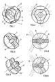
- Figures 1 and 2 show a fixing knob formed according to the invention which is formed by a nut 1 with a hexagonal base and by a casing with general reference number 2.
- This casing is formed by a disk 3 which is perpendicularly fixed to one of the bases of the nut 1 in a centered position and has a hole which is an extension of the threaded borehole 4 of the nut.
- the casing further comprises three equidistant radial arms 5 which are connected to the disk 3 and are separated from the nut 1.
- the arms 5 are further connected by arched intermediate sections 6.
- the arms 5 are hollow and open at their outer section 7, the width of this opening being such, together with the separation of the arched sections 6 of the nut 1, that a rod 8 can be introduced, represented by means of dotted lines in Figure 2 , through two consecutive openings 7, so that said rod is tangent to one of the faces of the nut 1.
- the rod 7, which can consist of the rod of a screwdriver, can be introduced through any two consecutive openings 7 and will serve to tighten or loosen the nut 1 with the required tension.
- the arms with reference number 5' run radially from the nut 1 and have a transverse passage 9, which passage will be of a section increasing towards the holes on both sides of the arms 5' so that the rod 8 can be introduced in a position tangent to one of the faces of the nut 1, as in the case of Figure 2 . Due to the widening of the passage 9 towards its hole the rod 8 can be introduced in two different positions 8 and 8' through the same passage, being supported on consecutive faces of the nut 1.
- Figures 5 and 6 show a variant in which the casing includes three arms with reference number 5", which are separated from one another at 120o angles.
- the arms 5" have passages 9 with an identical configuration to the knob of Figure 3 in order to allow introducing rods in directions 8 and 8' both tangent to consecutive faces of the nut 1, as shown in Figure 6 and in Figure 4 .
- a fixing or connecting knob is available which allows loosening and tightening the nut 1 with the help of only a screwdriver the rod of which will be introduced through the corresponding passage.
- the arrangement described allows reducing the dimensions of the nut 1 so that they protrude as little as possible from the surface on which it is arranged.
- the inclusion of the casing in the knob allows the assembly to be of a reduced height without it being any problem for its actuation.
- the knob of Figures 1 and 2 allows accessibility of the actuation rod 8 every 60o around the nut 1.
- the accessibility will take place every 80o, whereas in the embodiment of Figures 5 and 6 said accessibility will be every 60o as in the case of Figures 1 and 2 .
Landscapes
- Engineering & Computer Science (AREA)
- General Engineering & Computer Science (AREA)
- General Physics & Mathematics (AREA)
- Automation & Control Theory (AREA)
- Mechanical Engineering (AREA)
- Physics & Mathematics (AREA)
- Details Of Spanners, Wrenches, And Screw Drivers And Accessories (AREA)
- Lock And Its Accessories (AREA)
- Cookers (AREA)
- Mechanical Control Devices (AREA)
- Preventing Unauthorised Actuation Of Valves (AREA)
- Switches With Compound Operations (AREA)
- Wire Bonding (AREA)
- Polishing Bodies And Polishing Tools (AREA)
- Magnetic Heads (AREA)
Abstract
Description
- The present invention relates to a fixing knob used as a connecting part, being formed by a nut and a casing giving it a greater volume to make its actuation easier, especially with an auxiliary rod, for example with the rod of a screwdriver.
- The knob of the invention can be used as a fixing or connecting means identical to that of a normal nut but with the advantage of having means which make its actuation easier, having special application in the automotive industry.
- The nuts used for connecting or fixing parts consist of a core generally in the form of a square or straight hexagonal part provided with a threaded axial through borehole. In order to tighten or loosen these nuts it is necessary to have a suitable wrench, a tool which is not always available.
- This situation can present itself when having to tighten or loosen certain nuts of a vehicle, the tool supply of which does not usually include a wrench.
- In certain parts of an automobile, for example in the trunk, it is also necessary that certain nuts are visible but at the same time it is desirable that such nuts are of little height so that they protrude as little as possible, implying yet another difficulty when having to tighten and loosen the nuts.
- The object of the present invention is to eliminate the problems set forth by means of a fixing knob including a nut and having means that make the actuation of said nut with the hand easier and the necessary tightening thereof can be carried out with a rod, for example with the rod of a screwdriver, a tool which does traditionally enter into the tool supply of an automobile
- The knob of the invention is formed by a nut and an actuation casing. The nut can be of a square or hexagonal base.
- The casing forming part of the knob of the invention comprises a disk which is fixed in a position centered at one of the bases of the nut perpendicular to such nut, said base having a hole which is an extension of the threaded borehole of the nut. The casing also includes at least two arms radially arranged around the nut fixed to the disk. These arms have a passage through which an actuation rod can be introduced. The casing can include only two diametrically opposite or three angularly equidistant radial arms. Furthermore the arms can start from the core or be slightly separated from such core.
- As regards the passage of each arm, it can run transversally or longitudinally with respect thereto.
- The attached drawings show by way of a non-limiting example possible embodiments of the knob of the invention.
- A more detailed description of the invention will be made next, with reference to these drawings in which:
-
Figure 1 is a perspective view of a fixing knob formed according to the invention. -
Figure 2 is an upper plan view of the knobFigure 1 . -
Figure 3 shows a perspective view of a knob the casing of which includes two arms radially coming out from the nut. -
Figure 4 is an upper plan view of the knob ofFigure 3 . -
Figure 5 is a perspective view similar toFigure 3 of a knob with the radial arms coming out from the nut. -
Figure 6 is an upper plan view of the knob ofFigure 5 . -
Figures 1 and 2 show a fixing knob formed according to the invention which is formed by a nut 1 with a hexagonal base and by a casing withgeneral reference number 2. This casing is formed by adisk 3 which is perpendicularly fixed to one of the bases of the nut 1 in a centered position and has a hole which is an extension of the threadedborehole 4 of the nut. The casing further comprises three equidistantradial arms 5 which are connected to thedisk 3 and are separated from the nut 1. Thearms 5 are further connected by archedintermediate sections 6. - The
arms 5 are hollow and open at theirouter section 7, the width of this opening being such, together with the separation of thearched sections 6 of the nut 1, that arod 8 can be introduced, represented by means of dotted lines inFigure 2 , through twoconsecutive openings 7, so that said rod is tangent to one of the faces of the nut 1. - The
rod 7, which can consist of the rod of a screwdriver, can be introduced through any twoconsecutive openings 7 and will serve to tighten or loosen the nut 1 with the required tension. - In the case of
Figures 3 and 4 , the arms with reference number 5' run radially from the nut 1 and have atransverse passage 9, which passage will be of a section increasing towards the holes on both sides of the arms 5' so that therod 8 can be introduced in a position tangent to one of the faces of the nut 1, as in the case ofFigure 2 . Due to the widening of thepassage 9 towards its hole therod 8 can be introduced in twodifferent positions 8 and 8' through the same passage, being supported on consecutive faces of the nut 1. - Finally,
Figures 5 and 6 show a variant in which the casing includes three arms withreference number 5", which are separated from one another at 120º angles. - As in the case of
Figures 3 and 4 , thearms 5" havepassages 9 with an identical configuration to the knob ofFigure 3 in order to allow introducing rods indirections 8 and 8' both tangent to consecutive faces of the nut 1, as shown inFigure 6 and inFigure 4 . - With the constitution described a fixing or connecting knob is available which allows loosening and tightening the nut 1 with the help of only a screwdriver the rod of which will be introduced through the corresponding passage. The arrangement described allows reducing the dimensions of the nut 1 so that they protrude as little as possible from the surface on which it is arranged.
- The inclusion of the casing in the knob allows the assembly to be of a reduced height without it being any problem for its actuation.
- The knob of
Figures 1 and 2 allows accessibility of theactuation rod 8 every 60º around the nut 1. In the case ofFigures 3 and 4 the accessibility will take place every 80º, whereas in the embodiment ofFigures 5 and 6 said accessibility will be every 60º as in the case ofFigures 1 and 2 .
Claims (4)
- A fixing knob, characterized in that it is formed by a nut (1) and an actuation casing (2), the casing of which comprises a disk (3) fixed perpendicularly in a central position of one of the bases of the nut and provided with a hole which is an extension of the borehole (4) of said nut, and at least two arms (5) radially arranged around the nut and fixed to the disk; the arms of which are traversed by a passage (7-9) through which an actuation rod (8) can be introduced perpendicular to the shaft of the nut.
- A knob according to claim 1, characterized in that it comprises three equidistant hollowed arms (5) which are open on their outer section through as many other openings (7), every two consecutive openings of which establish a common passage which is tangent to one of the flat faces of the nut.
- A knob according to claim 1, characterized in that it comprises two diametrically opposite arms (5') and the passages (9) perpendicularly traverse the arms and are of a section increasing toward the holes.
- A knob according to claim 1 characterized in that it comprises three equidistant arms (5") and the passages (9) perpendicularly traverse the arms and are of a section increasing toward the holes.
Applications Claiming Priority (1)
| Application Number | Priority Date | Filing Date | Title |
|---|---|---|---|
| ES200602808U ES1064495Y (en) | 2006-12-28 | 2006-12-28 | FIXING KNOB |
Publications (2)
| Publication Number | Publication Date |
|---|---|
| EP1939468A1 true EP1939468A1 (en) | 2008-07-02 |
| EP1939468B1 EP1939468B1 (en) | 2010-04-28 |
Family
ID=38293868
Family Applications (1)
| Application Number | Title | Priority Date | Filing Date |
|---|---|---|---|
| EP07380390A Not-in-force EP1939468B1 (en) | 2006-12-28 | 2007-12-27 | Fixing knob |
Country Status (4)
| Country | Link |
|---|---|
| EP (1) | EP1939468B1 (en) |
| AT (1) | ATE466202T1 (en) |
| DE (1) | DE602007006141D1 (en) |
| ES (2) | ES1064495Y (en) |
Cited By (1)
| Publication number | Priority date | Publication date | Assignee | Title |
|---|---|---|---|---|
| JP2014040862A (en) * | 2012-08-22 | 2014-03-06 | Toyota Auto Body Co Ltd | Fastening fixture and electric power source connection structure using the same |
Citations (5)
| Publication number | Priority date | Publication date | Assignee | Title |
|---|---|---|---|---|
| US2049104A (en) * | 1935-04-29 | 1936-07-28 | R A Simpson Mfg Company Inc | Wing nut |
| US2259834A (en) * | 1940-09-14 | 1941-10-21 | G H Specialty Co | Wing nut and process for the manufacture thereof |
| US20030072636A1 (en) * | 2001-10-11 | 2003-04-17 | Boe Craig L. | Low profile fastener having a repositionable handle clip |
| CA2509923A1 (en) * | 2004-06-18 | 2005-12-18 | Joseph Bronner | Wall anchor system and method |
| US20050281634A1 (en) * | 2004-06-18 | 2005-12-22 | Patricia Tibbenham | Waffle stud for insert molded plastic members |
-
2006
- 2006-12-28 ES ES200602808U patent/ES1064495Y/en not_active Expired - Fee Related
-
2007
- 2007-12-27 DE DE602007006141T patent/DE602007006141D1/en active Active
- 2007-12-27 AT AT07380390T patent/ATE466202T1/en not_active IP Right Cessation
- 2007-12-27 EP EP07380390A patent/EP1939468B1/en not_active Not-in-force
- 2007-12-27 ES ES07380390T patent/ES2345165T3/en active Active
Patent Citations (5)
| Publication number | Priority date | Publication date | Assignee | Title |
|---|---|---|---|---|
| US2049104A (en) * | 1935-04-29 | 1936-07-28 | R A Simpson Mfg Company Inc | Wing nut |
| US2259834A (en) * | 1940-09-14 | 1941-10-21 | G H Specialty Co | Wing nut and process for the manufacture thereof |
| US20030072636A1 (en) * | 2001-10-11 | 2003-04-17 | Boe Craig L. | Low profile fastener having a repositionable handle clip |
| CA2509923A1 (en) * | 2004-06-18 | 2005-12-18 | Joseph Bronner | Wall anchor system and method |
| US20050281634A1 (en) * | 2004-06-18 | 2005-12-22 | Patricia Tibbenham | Waffle stud for insert molded plastic members |
Cited By (3)
| Publication number | Priority date | Publication date | Assignee | Title |
|---|---|---|---|---|
| JP2014040862A (en) * | 2012-08-22 | 2014-03-06 | Toyota Auto Body Co Ltd | Fastening fixture and electric power source connection structure using the same |
| CN103629223A (en) * | 2012-08-22 | 2014-03-12 | 丰田车体株式会社 | Fastening implement and a power connection structure using the same |
| CN103629223B (en) * | 2012-08-22 | 2016-01-13 | 丰田车体株式会社 | Power connection structure |
Also Published As
| Publication number | Publication date |
|---|---|
| ES1064495U (en) | 2007-03-16 |
| DE602007006141D1 (en) | 2010-06-10 |
| ES2345165T3 (en) | 2010-09-16 |
| ES1064495Y (en) | 2007-06-16 |
| ATE466202T1 (en) | 2010-05-15 |
| EP1939468B1 (en) | 2010-04-28 |
Similar Documents
| Publication | Publication Date | Title |
|---|---|---|
| US20090220321A1 (en) | Fastening metal fitting | |
| SE532106C2 (en) | Locking system comprising a fastener and a lock washer | |
| CN102027247A (en) | U-nut fastener assembly | |
| EP1939468B1 (en) | Fixing knob | |
| EP2522862A1 (en) | Fastening assembly | |
| SE0802627A1 (en) | A locking plate for use in a locking arrangement and such locking arrangement | |
| US10005147B2 (en) | Soldering tip fastening system | |
| US5700062A (en) | Wheel cover adjustable in its size | |
| EP3176462B1 (en) | Air spring bellows with recessed bead ring screws | |
| EP2416054A2 (en) | Components for an assembly-type frame | |
| US20060280550A1 (en) | Profile connecting system | |
| JP4141202B2 (en) | Screw head and fastening tool | |
| CN109428295A (en) | Cable stuffing-box | |
| KR102944107B1 (en) | Rotatable Bracket Bolt | |
| JP3114840U (en) | Tightening bolt structure | |
| CA2352652C (en) | Connection element for two components, one of which is tubular | |
| KR200397048Y1 (en) | A connector for square pipe | |
| US7246965B2 (en) | Method of assembling a link to a support, and a vibration-damping device manufactured by said method | |
| JP6829864B2 (en) | Hanging bolt support bracket | |
| JP4372037B2 (en) | Socket exchange type wrench | |
| US20090019812A1 (en) | Anchoring Apparatus and Method | |
| EP3486520A1 (en) | Pneumatic assembly for a motor vehicle | |
| CN211332947U (en) | Special sleeve for self-locking nut | |
| DE102018001137B3 (en) | Engine assembly | |
| KR100812882B1 (en) | Fastener |
Legal Events
| Date | Code | Title | Description |
|---|---|---|---|
| PUAI | Public reference made under article 153(3) epc to a published international application that has entered the european phase |
Free format text: ORIGINAL CODE: 0009012 |
|
| AK | Designated contracting states |
Kind code of ref document: A1 Designated state(s): AT BE BG CH CY CZ DE DK EE ES FI FR GB GR HU IE IS IT LI LT LU LV MC MT NL PL PT RO SE SI SK TR |
|
| AX | Request for extension of the european patent |
Extension state: AL BA HR MK RS |
|
| 17P | Request for examination filed |
Effective date: 20081218 |
|
| AKX | Designation fees paid |
Designated state(s): AT BE BG CH CY CZ DE DK EE ES FI FR GB GR HU IE IS IT LI LT LU LV MC MT NL PL PT RO SE SI SK TR |
|
| GRAP | Despatch of communication of intention to grant a patent |
Free format text: ORIGINAL CODE: EPIDOSNIGR1 |
|
| GRAS | Grant fee paid |
Free format text: ORIGINAL CODE: EPIDOSNIGR3 |
|
| GRAA | (expected) grant |
Free format text: ORIGINAL CODE: 0009210 |
|
| AK | Designated contracting states |
Kind code of ref document: B1 Designated state(s): AT BE BG CH CY CZ DE DK EE ES FI FR GB GR HU IE IS IT LI LT LU LV MC MT NL PL PT RO SE SI SK TR |
|
| REG | Reference to a national code |
Ref country code: GB Ref legal event code: FG4D |
|
| REG | Reference to a national code |
Ref country code: CH Ref legal event code: EP |
|
| REG | Reference to a national code |
Ref country code: IE Ref legal event code: FG4D |
|
| REF | Corresponds to: |
Ref document number: 602007006141 Country of ref document: DE Date of ref document: 20100610 Kind code of ref document: P |
|
| REG | Reference to a national code |
Ref country code: NL Ref legal event code: VDEP Effective date: 20100428 |
|
| REG | Reference to a national code |
Ref country code: ES Ref legal event code: FG2A Ref document number: 2345165 Country of ref document: ES Kind code of ref document: T3 |
|
| LTIE | Lt: invalidation of european patent or patent extension |
Effective date: 20100428 |
|
| PG25 | Lapsed in a contracting state [announced via postgrant information from national office to epo] |
Ref country code: NL Free format text: LAPSE BECAUSE OF FAILURE TO SUBMIT A TRANSLATION OF THE DESCRIPTION OR TO PAY THE FEE WITHIN THE PRESCRIBED TIME-LIMIT Effective date: 20100428 Ref country code: SE Free format text: LAPSE BECAUSE OF FAILURE TO SUBMIT A TRANSLATION OF THE DESCRIPTION OR TO PAY THE FEE WITHIN THE PRESCRIBED TIME-LIMIT Effective date: 20100428 Ref country code: LT Free format text: LAPSE BECAUSE OF FAILURE TO SUBMIT A TRANSLATION OF THE DESCRIPTION OR TO PAY THE FEE WITHIN THE PRESCRIBED TIME-LIMIT Effective date: 20100428 |
|
| PG25 | Lapsed in a contracting state [announced via postgrant information from national office to epo] |
Ref country code: SI Free format text: LAPSE BECAUSE OF FAILURE TO SUBMIT A TRANSLATION OF THE DESCRIPTION OR TO PAY THE FEE WITHIN THE PRESCRIBED TIME-LIMIT Effective date: 20100428 Ref country code: LV Free format text: LAPSE BECAUSE OF FAILURE TO SUBMIT A TRANSLATION OF THE DESCRIPTION OR TO PAY THE FEE WITHIN THE PRESCRIBED TIME-LIMIT Effective date: 20100428 Ref country code: IS Free format text: LAPSE BECAUSE OF FAILURE TO SUBMIT A TRANSLATION OF THE DESCRIPTION OR TO PAY THE FEE WITHIN THE PRESCRIBED TIME-LIMIT Effective date: 20100828 Ref country code: FI Free format text: LAPSE BECAUSE OF FAILURE TO SUBMIT A TRANSLATION OF THE DESCRIPTION OR TO PAY THE FEE WITHIN THE PRESCRIBED TIME-LIMIT Effective date: 20100428 Ref country code: AT Free format text: LAPSE BECAUSE OF FAILURE TO SUBMIT A TRANSLATION OF THE DESCRIPTION OR TO PAY THE FEE WITHIN THE PRESCRIBED TIME-LIMIT Effective date: 20100428 |
|
| PG25 | Lapsed in a contracting state [announced via postgrant information from national office to epo] |
Ref country code: PL Free format text: LAPSE BECAUSE OF FAILURE TO SUBMIT A TRANSLATION OF THE DESCRIPTION OR TO PAY THE FEE WITHIN THE PRESCRIBED TIME-LIMIT Effective date: 20100428 Ref country code: CY Free format text: LAPSE BECAUSE OF FAILURE TO SUBMIT A TRANSLATION OF THE DESCRIPTION OR TO PAY THE FEE WITHIN THE PRESCRIBED TIME-LIMIT Effective date: 20100526 |
|
| PG25 | Lapsed in a contracting state [announced via postgrant information from national office to epo] |
Ref country code: PT Free format text: LAPSE BECAUSE OF FAILURE TO SUBMIT A TRANSLATION OF THE DESCRIPTION OR TO PAY THE FEE WITHIN THE PRESCRIBED TIME-LIMIT Effective date: 20100830 Ref country code: DK Free format text: LAPSE BECAUSE OF FAILURE TO SUBMIT A TRANSLATION OF THE DESCRIPTION OR TO PAY THE FEE WITHIN THE PRESCRIBED TIME-LIMIT Effective date: 20100428 Ref country code: EE Free format text: LAPSE BECAUSE OF FAILURE TO SUBMIT A TRANSLATION OF THE DESCRIPTION OR TO PAY THE FEE WITHIN THE PRESCRIBED TIME-LIMIT Effective date: 20100428 |
|
| PG25 | Lapsed in a contracting state [announced via postgrant information from national office to epo] |
Ref country code: SK Free format text: LAPSE BECAUSE OF FAILURE TO SUBMIT A TRANSLATION OF THE DESCRIPTION OR TO PAY THE FEE WITHIN THE PRESCRIBED TIME-LIMIT Effective date: 20100428 Ref country code: CZ Free format text: LAPSE BECAUSE OF FAILURE TO SUBMIT A TRANSLATION OF THE DESCRIPTION OR TO PAY THE FEE WITHIN THE PRESCRIBED TIME-LIMIT Effective date: 20100428 Ref country code: BE Free format text: LAPSE BECAUSE OF FAILURE TO SUBMIT A TRANSLATION OF THE DESCRIPTION OR TO PAY THE FEE WITHIN THE PRESCRIBED TIME-LIMIT Effective date: 20100428 Ref country code: RO Free format text: LAPSE BECAUSE OF FAILURE TO SUBMIT A TRANSLATION OF THE DESCRIPTION OR TO PAY THE FEE WITHIN THE PRESCRIBED TIME-LIMIT Effective date: 20100428 |
|
| PLBE | No opposition filed within time limit |
Free format text: ORIGINAL CODE: 0009261 |
|
| STAA | Information on the status of an ep patent application or granted ep patent |
Free format text: STATUS: NO OPPOSITION FILED WITHIN TIME LIMIT |
|
| 26N | No opposition filed |
Effective date: 20110131 |
|
| PG25 | Lapsed in a contracting state [announced via postgrant information from national office to epo] |
Ref country code: GR Free format text: LAPSE BECAUSE OF FAILURE TO SUBMIT A TRANSLATION OF THE DESCRIPTION OR TO PAY THE FEE WITHIN THE PRESCRIBED TIME-LIMIT Effective date: 20100729 |
|
| PG25 | Lapsed in a contracting state [announced via postgrant information from national office to epo] |
Ref country code: MC Free format text: LAPSE BECAUSE OF NON-PAYMENT OF DUE FEES Effective date: 20101231 |
|
| REG | Reference to a national code |
Ref country code: FR Ref legal event code: ST Effective date: 20110831 |
|
| PG25 | Lapsed in a contracting state [announced via postgrant information from national office to epo] |
Ref country code: IE Free format text: LAPSE BECAUSE OF NON-PAYMENT OF DUE FEES Effective date: 20101227 Ref country code: FR Free format text: LAPSE BECAUSE OF NON-PAYMENT OF DUE FEES Effective date: 20110103 |
|
| REG | Reference to a national code |
Ref country code: DE Ref legal event code: R119 Ref document number: 602007006141 Country of ref document: DE Effective date: 20110701 |
|
| PG25 | Lapsed in a contracting state [announced via postgrant information from national office to epo] |
Ref country code: DE Free format text: LAPSE BECAUSE OF NON-PAYMENT OF DUE FEES Effective date: 20110701 |
|
| PG25 | Lapsed in a contracting state [announced via postgrant information from national office to epo] |
Ref country code: MT Free format text: LAPSE BECAUSE OF FAILURE TO SUBMIT A TRANSLATION OF THE DESCRIPTION OR TO PAY THE FEE WITHIN THE PRESCRIBED TIME-LIMIT Effective date: 20100428 Ref country code: IT Free format text: LAPSE BECAUSE OF NON-PAYMENT OF DUE FEES Effective date: 20101227 |
|
| PGFP | Annual fee paid to national office [announced via postgrant information from national office to epo] |
Ref country code: IT Payment date: 20101231 Year of fee payment: 4 |
|
| REG | Reference to a national code |
Ref country code: ES Ref legal event code: FD2A Effective date: 20120206 |
|
| PG25 | Lapsed in a contracting state [announced via postgrant information from national office to epo] |
Ref country code: ES Free format text: LAPSE BECAUSE OF NON-PAYMENT OF DUE FEES Effective date: 20101228 |
|
| REG | Reference to a national code |
Ref country code: CH Ref legal event code: PL |
|
| GBPC | Gb: european patent ceased through non-payment of renewal fee |
Effective date: 20111227 |
|
| PG25 | Lapsed in a contracting state [announced via postgrant information from national office to epo] |
Ref country code: HU Free format text: LAPSE BECAUSE OF FAILURE TO SUBMIT A TRANSLATION OF THE DESCRIPTION OR TO PAY THE FEE WITHIN THE PRESCRIBED TIME-LIMIT Effective date: 20101029 Ref country code: BG Free format text: LAPSE BECAUSE OF FAILURE TO SUBMIT A TRANSLATION OF THE DESCRIPTION OR TO PAY THE FEE WITHIN THE PRESCRIBED TIME-LIMIT Effective date: 20100428 Ref country code: LU Free format text: LAPSE BECAUSE OF NON-PAYMENT OF DUE FEES Effective date: 20101227 |
|
| PG25 | Lapsed in a contracting state [announced via postgrant information from national office to epo] |
Ref country code: GB Free format text: LAPSE BECAUSE OF NON-PAYMENT OF DUE FEES Effective date: 20111227 Ref country code: LI Free format text: LAPSE BECAUSE OF NON-PAYMENT OF DUE FEES Effective date: 20111231 Ref country code: TR Free format text: LAPSE BECAUSE OF FAILURE TO SUBMIT A TRANSLATION OF THE DESCRIPTION OR TO PAY THE FEE WITHIN THE PRESCRIBED TIME-LIMIT Effective date: 20100428 Ref country code: CH Free format text: LAPSE BECAUSE OF NON-PAYMENT OF DUE FEES Effective date: 20111231 |
|
| PG25 | Lapsed in a contracting state [announced via postgrant information from national office to epo] |
Ref country code: IT Free format text: LAPSE BECAUSE OF NON-PAYMENT OF DUE FEES Effective date: 20111227 |
|
| PG25 | Lapsed in a contracting state [announced via postgrant information from national office to epo] |
Ref country code: BG Free format text: LAPSE BECAUSE OF FAILURE TO SUBMIT A TRANSLATION OF THE DESCRIPTION OR TO PAY THE FEE WITHIN THE PRESCRIBED TIME-LIMIT Effective date: 20100728 |