EP1939462A2 - Actuator - Google Patents
Actuator Download PDFInfo
- Publication number
- EP1939462A2 EP1939462A2 EP07024794A EP07024794A EP1939462A2 EP 1939462 A2 EP1939462 A2 EP 1939462A2 EP 07024794 A EP07024794 A EP 07024794A EP 07024794 A EP07024794 A EP 07024794A EP 1939462 A2 EP1939462 A2 EP 1939462A2
- Authority
- EP
- European Patent Office
- Prior art keywords
- piston
- cylinder
- stopper
- main body
- nail
- Prior art date
- Legal status (The legal status is an assumption and is not a legal conclusion. Google has not performed a legal analysis and makes no representation as to the accuracy of the status listed.)
- Granted
Links
Images



Classifications
-
- F—MECHANICAL ENGINEERING; LIGHTING; HEATING; WEAPONS; BLASTING
- F15—FLUID-PRESSURE ACTUATORS; HYDRAULICS OR PNEUMATICS IN GENERAL
- F15B—SYSTEMS ACTING BY MEANS OF FLUIDS IN GENERAL; FLUID-PRESSURE ACTUATORS, e.g. SERVOMOTORS; DETAILS OF FLUID-PRESSURE SYSTEMS, NOT OTHERWISE PROVIDED FOR
- F15B15/00—Fluid-actuated devices for displacing a member from one position to another; Gearing associated therewith
- F15B15/19—Pyrotechnical actuators
-
- F—MECHANICAL ENGINEERING; LIGHTING; HEATING; WEAPONS; BLASTING
- F15—FLUID-PRESSURE ACTUATORS; HYDRAULICS OR PNEUMATICS IN GENERAL
- F15B—SYSTEMS ACTING BY MEANS OF FLUIDS IN GENERAL; FLUID-PRESSURE ACTUATORS, e.g. SERVOMOTORS; DETAILS OF FLUID-PRESSURE SYSTEMS, NOT OTHERWISE PROVIDED FOR
- F15B15/00—Fluid-actuated devices for displacing a member from one position to another; Gearing associated therewith
- F15B15/20—Other details, e.g. assembly with regulating devices
- F15B15/26—Locking mechanisms
- F15B15/261—Locking mechanisms using positive interengagement, e.g. balls and grooves, for locking in the end positions
Definitions
- the present invention relates to an actuator used in an airbag type restraining device or the like.
- an occupant restraining device or a pedestrian protection device of a vehicle there is, in addition to an airbag type restraining device, a device for lifting up the hood of a vehicle in order to protect a pedestrian and a device for retracting the steering wheel (shaft/column), and a pyrotechnic actuator is used in such devices.
- US-B1 No. 6,675,692 is an invention relating to a pyrotechnic actuator.
- a piston 2 is slidably disposed within a housing 1 and is driven by a detonator 3.
- An oblong cavity 2b is formed on the piston 2, and a projection 9 is caused to pass therethrough.
- a lock (locking element) 8 is disposed so as to surround the projection 9. When a free end 8a abuts on the projection 9 before activation, the piston is inhibited from moving.
- an object corresponding to the lock 8 shown in Fig. 1 is formed in plurality.
- a piston is disposed within a cylinder and a piston fixing member 13 locks a piston 2 prior to activation (upper left of the drawing).
- the fixing member 13 is in the form of a washer, and by fitting an inner peripheral portion thereof into an annular groove 12 formed on the piston 2, the piston is inhibited from moving before activation.
- the present invention provides an actuator including:
- the invention also provides an actuator including:
- the present invention provides an actuator that is capable of fixing a piston by means of one component before and after activation, and has a simple structure.
- the nail portion operates, similarly to a blade spring, to inhibit the movement of the piston before the ignition device is activated, and to inhibit backward movement of the piston after the ignition device is activated.
- At least the nail portion of the stopper may be formed of an elastic member, but the entirety of the stopper may be formed from an elastic thin metal sheet. If the entirety of the stopper is formed from an elastic thin metal sheet, a predetermined section of the main body portion may be cut out into, for example, a rectangular, square, trapezoidal, or triangular shape (however, one side of the predetermined section is left uncut and the remaining sides are cut out) and one remaining side may be bent to form the nail portion.
- the nail portion operates, similarly to a blade spring, to inhibit the movement of the piston before the ignition device is activated, and to inhibit backward movement of the piston after the ignition device is activated.
- At least the nail portion of the stopper may be formed of an elastic member, but the entirety of the stopper may be formed from an elastic thin metal sheet. If the entirety of the stopper is formed from an elastic thin metal sheet, a predetermined section of the main body portion may be cut out into, for example, a rectangular, square, trapezoidal, or triangular shape (however, one side of the predetermined section is left uncut and the remaining sides are cut out) and one remaining side may be bent to form the nail portion.
- the movement of the piston before activation and the backward movement of the piston after activation are inhibited by one component attached to the cylinder or piston.
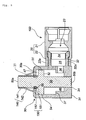
- Fig. 1 and Fig. 2 each are a longitudinal sectional view of an actuator, Fig. 1 showing a state before activation and Fig. 2 showing a state after activation.
- An outer shell of an actuator 10 is formed by integrating an igniter collar 20 and a cylinder 30.
- the igniter collar 20 has a main body portion 21 in contact with an igniter 23 and a collar tubular joining portion 22 extended from the main body portion 21.
- the cylinder 30 has a tubular piston accommodating portion 31 and a cylinder tubular joining portion 32 protruding from a peripheral surface of the piston accommodating portion 31.
- the igniter 23 is fixed to the cylinder tubular joining portion 32 by the igniter collar 20 and thereby connected to the cylinder 30.
- the igniter collar 20 and the cylinder 30 are joined to each other in a state in which the cylinder tubular joining portion 32 is inserted into the collar tubular joining portion 22.
- the cylinder tubular joining portion 32 which is provided with a step (groove 32a) on the outer surface in advance, is covered by the collar tubular joining portion 22.
- the collar tubular portion 22 has originally no groove, however, when it covers the cylinder tubular joining portion, it is deformed to match the outer shape of the cylinder tubular joining portion 32, so that a groove 22a having the same shape as a groove 32a may be formed, thereby joining both tubular joining portions.
- the igniter 23 may be fixed to the cylinder tubular joining portion 32 without using the igniter collar 20.
- the igniter 23 (the one used in a known actuator or gas generator for an airbag can be used) is fixed within an igniter accommodating space 25 surrounded by the igniter collar 20, a cylinder main body portion 31 and a cylinder tubular joining portion 32.
- the cylinder 30 has at both end sides thereof a first opening portion 33 and a second opening portion 34, and has on a side surface side thereof a communication hole 36 communicated with the igniter accommodating space 25.
- a step is formed on an inner peripheral surface between the first opening portion 33 and the second opening portion 34, and an annular surface 37 facing the first opening portion 33 is provided in the step potion.
- a tubular stopper 40 is attached between the first opening portion 33 of the cylinder main body portion 31 and the annular surface 37.
- the tubular stopper 40 has a stopper main body portion 41 that is in contact with the cylinder main body portion 31, and a nail portion 42 that is obtained by cutting out a desired section of the stopper main body portion 41 into a rectangular shape (however, the three sides are cut out and the one narrow side is left uncut) and bending a leading end portion of the rectangle inward (inside a second cylinder accommodating space 47).
- the nail portion 42 may be formed by firmly fixing a plate-like object to the main body portion 41. It is preferred that the nail portion 42 be formed in plurality (two through eight, for example) at regular intervals in a peripheral direction.
- the stopper 40 or the nail portion 42 is made of an elastic material such as a thin metal sheet of a stainless steel, iron or aluminum or the like.
- the nail portion 42 performs a predetermined stopper function, similarly to a blade spring, by being deformed when external force is applied thereto and by being restored immediately to its initial shape or a shape similar to the initial shape when the external force is removed.
- a piston 50 accommodated in the cylinder 30 has, in a desired section in the length direction, a disk-like enlarged diameter portion 51 in which an outer diameter is enlarged.
- the disk-like enlarged diameter portion 51 has an annular second surface 53 facing the first opening portion 33 and an annular first surface 52 facing the second opening portion 34 side.
- a peripheral surface 54 of the disk-like enlarged diameter portion 51 abuts on the stopper main body portion 41, and a part of the annular first surface 52 abuts on the annular surface 37.
- the inside of the cylinder 30 is divided into a first piston accommodating space 46 and a second piston accommodating space 47 by the disk-like enlarged diameter portion 51.
- one end surface 50a of the piston 50 faces the first opening portion 33 but does not protrude from the first opening portion 33.
- the other end surface 50b of the piston 50 protrudes from the second opening portion 34 to the outside.
- the stopper 40 is fixed by causing one end side opening portion thereof to abut on a stopper fixing member 45 attached to the first opening portion 33 side, an outer peripheral surface of the same to abut on the cylinder main body portion 31, and a part of an inner peripheral surface of the same to abut on the peripheral surface 54 of the disk-like enlarged diameter portion 51.
- the stopper fixing member 45 may have an annular shape and elasticity, and is fixed by bending a peripheral edge 30a of the first opening portion 33 inward.
- the tubular stopper 40 may not have a complete tubular shape, and may have a slit 43 passing through vertically (or a slit 43 that does not pass through), as shown in Fig. 3 .
- the entirety of the stopper 40 is formed from an elastic member. Then, when such stopper 40 is inserted into the cylinder 30, the stopper 40 is inserted by pushing it so that the slit 43 is closed, and, when the force of pushing is released after the insertion, the slit 43 is restored to its original state so as to be opened, thus the insertion and fixation to the cylinder 30 can be performed easily.
- a combustion product (flame, high-temperature gas, shockwave, or the like) is generated from an ignition portion 24.
- the generated combustion product flows into the first piston accommodating space 46 through the igniter accommodating space 25 facing the ignition portion 24 and the communication hole 36.
- the annular first surface 52 of the disk-like enlarged diameter portion 51 is pressed by the combustion product, whereby the piston 50 moves in the axial direction.
- the nail portion 42 is pressed toward the main body portion 41 and deformed, thus the movement of the piston 50 is not inhibited.
- Fig. 4 and Fig. 5 each are a longitudinal sectional view of an actuator of another embodiment, Fig. 4 showing a state before activation and Fig. 5 showing a state after activation.
- the basic structure of an actuator 100 shown in Fig. 4 and Fig. 5 is the same as that of the actuator 10 shown in Fig. 1 and Fig. 2 , and the same reference numerals indicate the same components.
- a tubular stopper 140 is attached to an outer peripheral surface between the disk-like enlarged diameter portion 51 and the end surface 50a of the piston 50.
- the tubular stopper 140 has a stopper main body 141 that is in contact with the piston 50, and a nail portion 142 that is obtained by cutting out a desired section of the stopper main body portion 141 into a rectangular shape (however, the three sides are cut out and the one narrow side is left uncut) and bending a leading end portion of the rectangle outward (inside the second cylinder accommodating space 47).
- the nail portion 142 may be formed by firmly fixing a plate like object to the main body portion 141.
- the stopper 140 or the nail portion 142 is made of an elastic material such as a thin metal sheet of a stainless steel, iron or aluminum.
- the nail portion 142 is deformed, similarly to a blade spring, when external force is applied thereto, and is restored immediately to its initial shape by removing the external force.
- An annular groove (or a plurality of concave portions) 55 is formed on an outer peripheral surface of the piston 50 between the disk-like enlarged diameter portion 51 and the stopper 140, and a stopper fixing member 150 for fixing the stopper 140 to the piston 50 is formed at a position on the stopper 140 that faces the annular groove 55.
- the stopper main body portion 141 protrudes, along with the piston 50, from the first opening portion 33 of the cylinder 30 to the outside, and the nail portion 142 is positioned inside the first opening portion 33.
- the nail portion 142 spreads wider than the diameter of the first opening portion 33, and an outer surface of the nail portion 142 abuts on and presses an inner surface of the first opening portion 33, thus, before the igniter 23 is activated, the piston 50 is inhibited from moving in the axial direction.
- the stopper fixing member 150 is integrated with the tubular stopper 140, and has a main body portion 151 of the stopper fixing member, and a nail portion 152 that is obtained by cutting out a desired section of the stopper fixing member main body portion 151 into a rectangular shape (however, the three sides are cut out and the one narrow side is left uncut) and bending a leading end portion of the rectangle toward the inside of the annular groove 55.
- the nail portion 152 is tightly fitted in the annular groove 55, and the tubular stopper 140 is fixed to the piston 50 by means of this nail portion 152.
- the tubular stopper 140 may be fixed to the piston 50 by deforming (denting) the tubular stopper 140 to have the same shape as the annular groove 55, without using the stopper fixing member 150.
- the tubular stopper 140 may not have a complete tubular shape, and may have a slit 143 passing through vertically (or a slit 143 that does not pass through), as shown in Fig. 6 .
- the entirety of the stopper 140 is formed from an elastic member. Then, when such stopper 140 is inserted into the cylinder 30, the stopper 140 is inserted by pushing it so that the slit 143 is closed, and, when the force of pushing is released after the insertion, the slit 143 is restored to its original state so as to be opened, thus the insertion and fixation to the cylinder 30 can be performed easily.
- a combustion product (flame, high-temperature gas, shockwave, or the like) is generated from the ignition portion 24.
- the generated combustion product flows into the first piston accommodating space 46 through the igniter accommodating space 25 facing the ignition portion 24 and the communication hole 36.
- the annular first surface 52 of the disk-like enlarged diameter portion 51 is pressed by the combustion product, whereby the piston 50 moves in the axial direction.
- the nail portion 142 is pressed toward the main body portion 141 and deformed, thus the movement of the piston 50 is not inhibited.
- the nail portion 142 when the piston 50 protrudes from the first opening portion 33 by a predetermined length, the nail portion 142, that is once pressed toward the main body portion 141 and deformed, is restored into its initial shape or a shape similar to the initial shape, thus the nail portion 142 spreads wider than the diameter of the first opening portion 33. Therefore, the nail portion 142 abuts on an outer side surface 30a of the first opening portion 33, and the piston 50 is inhibited from being retracted into the cylinder 30.
- the operation of the stopper fixing member 150 prevents the stopper 140 from being dropped from the piston 50, thus the operation of the stopper 140 for inhibiting the movement of the piston 50 remains unaffected.
Landscapes
- Engineering & Computer Science (AREA)
- Physics & Mathematics (AREA)
- Fluid Mechanics (AREA)
- Mechanical Engineering (AREA)
- General Engineering & Computer Science (AREA)
- Chemical & Material Sciences (AREA)
- Analytical Chemistry (AREA)
- Actuator (AREA)
- Portable Nailing Machines And Staplers (AREA)
Abstract
a cylinder connected to an ignition device;
a piston slidably accommodated inside the cylinder, the piston having, in a desired section in the length direction, an enlarged diameter portion in which an outer diameter is enlarged;
a cylindrical stopper attached to an inner peripheral surface of the cylinder, the stopper including,
a main body portion which is fixed to the inner peripheral surface of the cylinder, and
a nail portion which inwardly projects from the main body portion and is formed of an elastic material, wherein
before activation of the ignition device, the piston is inhibited from moving in an axial direction by causing the nail portion to contact a part of the enlarged diameter portion,
after activation of the ignition device, the piston is inhibited from moving in a backward direction by causing the nail portion to contact another part of the enlarged diameter portion.
Description
- The present invention relates to an actuator used in an airbag type restraining device or the like.
- As an occupant restraining device or a pedestrian protection device of a vehicle, there is, in addition to an airbag type restraining device, a device for lifting up the hood of a vehicle in order to protect a pedestrian and a device for retracting the steering wheel (shaft/column), and a pyrotechnic actuator is used in such devices.
- There is known actuator in which a pin (piston) is pushed out or retracted in activation, and, in either case, it is necessary to fix the piston before activation so that it does not move.
- In an actuator combined with the above-mentioned restraining device, even after driving the piston, the piston needs to be prevented from returning to its initial position, thus it is preferred, in terms of size and weight reduction of the entire device, that the structure for inhibiting the movement of the piston before and after the activation be uncomplicated/simple.
-
US-B1 No. 6,675,692 is an invention relating to a pyrotechnic actuator. As shown inFig. 1 , there is disclosed an actuator in which a piston 2 is slidably disposed within ahousing 1 and is driven by a detonator 3. An oblong cavity 2b is formed on the piston 2, and a projection 9 is caused to pass therethrough. A lock (locking element) 8 is disposed so as to surround the projection 9. When a free end 8a abuts on the projection 9 before activation, the piston is inhibited from moving. InFig. 2 , an object corresponding to the lock 8 shown inFig. 1 is formed in plurality. - In Fig. 7, two studs 2z that are attached to the piston 2 are bent inward by at least a certain amount of force and pass through the piston 2 with respect to the projection. There is disclosed in the 11th through 17th lines of Column 5 that the piston 2 is fixed by the studs 2z before and after activation.
- In the actuator of
EP-B1 No. 1162333 , a piston is disposed within a cylinder and a piston fixing member 13 locks a piston 2 prior to activation (upper left of the drawing). The fixing member 13 is in the form of a washer, and by fitting an inner peripheral portion thereof into an annular groove 12 formed on the piston 2, the piston is inhibited from moving before activation. - The present invention provides an actuator including:
- a cylinder connected to an ignition device;
- a piston slidably accommodated inside the cylinder, the piston having, in a desired section in the length direction, an enlarged diameter portion in which an outer diameter is enlarged;
- a cylindrical stopper attached to an inner peripheral surface of the cylinder, the stopper including,
a main body portion which is fixed to the inner peripheral surface of the cylinder, and
a nail portion which inwardly projects from the main body portion and is formed of an elastic material, - The invention also provides an actuator including:
- a cylinder connected to an ignition device;
- a piston slidably accommodated inside the cylinder;
- a cylindrical stopper attached to an outer peripheral surface of the piston, the stopper including,
a main body portion which is fixed to the outer peripheral surface of the piston, and
a nail portion which outwardly projects from the main body portion and is formed of an elastic material, wherein
before the activation of the ignition device, the piston is inhibited from moving in an axial direction by causing the nail portion to contact a peripheral edge of an opening portion of the cylinder,
after the activation of the ignition device, the piston is inhibited from moving in a backward direction by the nail portion which has popped out of the cylinder and spreads wider than a diameter of the opening portion of the cylinder. - The present invention will become more fully understood from the detailed description given hereinbelow and the accompanying drawings which are given by way of illustration only, and thus are not limitative of the present invention and wherein:
-
Fig. 1 shows a longitudinal sectional view of the actuator of the present invention in a state before activation; -
Fig. 2 shows a longitudinal sectional view of the actuator of the present invention in a state after activation; -
Fig. 3 shows a perspective view of a stopper of an embodiment different from that shown inFig. 1 ; -
Fig. 4 shows a longitudinal sectional view of the actuator of another embodiment of the present invention in a state before activation; -
Fig. 5 shows a longitudinal sectional view of the actuator of another embodiment of the present invention in a state after activation; and -
Fig. 6 shows a perspective view of the stopper of an embodiment different from that shown inFig. 4 . - In
Fig. 1 ofUS-B1 No. 6,675,692 , the projection 9 deforms the free end 8a of the lock 8 at the time of activation and moves from a 2b' space to a 2b" space, but it is difficult to completely fix the piston after activation because of the wide 2b" space. Also, inFig. 2 , it is possible to fix the piston after activation, but the structure is complicated since a plurality of the locks 8 are used. - In Fig. 7 of
US-B1 No. 6,675,692 , on the other hand, there is disclosed that the piston can be fixed before and after activation, but the movement of the piston is not locked in the drawing, particularly before activation, thus it is assumed that the locking function is not exercised sufficiently. - In the actuator of
EP-B1 No. 1162333 , when the piston moves upon activation of an igniter 5, the fixing member 13 is deformed (upper right of the drawing) and the piston is pushed out, but since the fixing member functions to inhibit the backward movement of the piston, the piston is inhibited from returning its initial position after the activation. However, in this structure, fixation of the fixing member itself is complicated, and in the embodiment, the fixing member is fixed between the actuator and a container A accommodating therein the entire actuator. - The present invention provides an actuator that is capable of fixing a piston by means of one component before and after activation, and has a simple structure.
- By using the stopper having the nail portion made of an elastic member, the nail portion operates, similarly to a blade spring, to inhibit the movement of the piston before the ignition device is activated, and to inhibit backward movement of the piston after the ignition device is activated.
- At least the nail portion of the stopper may be formed of an elastic member, but the entirety of the stopper may be formed from an elastic thin metal sheet. If the entirety of the stopper is formed from an elastic thin metal sheet, a predetermined section of the main body portion may be cut out into, for example, a rectangular, square, trapezoidal, or triangular shape (however, one side of the predetermined section is left uncut and the remaining sides are cut out) and one remaining side may be bent to form the nail portion.
- By using the stopper having the nail portion made of an elastic member, the nail portion operates, similarly to a blade spring, to inhibit the movement of the piston before the ignition device is activated, and to inhibit backward movement of the piston after the ignition device is activated.
- At least the nail portion of the stopper may be formed of an elastic member, but the entirety of the stopper may be formed from an elastic thin metal sheet. If the entirety of the stopper is formed from an elastic thin metal sheet, a predetermined section of the main body portion may be cut out into, for example, a rectangular, square, trapezoidal, or triangular shape (however, one side of the predetermined section is left uncut and the remaining sides are cut out) and one remaining side may be bent to form the nail portion.
- According to the actuator of the present invention, the movement of the piston before activation and the backward movement of the piston after activation are inhibited by one component attached to the cylinder or piston.
-
Fig. 1 andFig. 2 each are a longitudinal sectional view of an actuator,Fig. 1 showing a state before activation andFig. 2 showing a state after activation. An outer shell of anactuator 10 is formed by integrating anigniter collar 20 and acylinder 30. Theigniter collar 20 has amain body portion 21 in contact with anigniter 23 and a collar tubular joiningportion 22 extended from themain body portion 21. Thecylinder 30 has a tubularpiston accommodating portion 31 and a cylinder tubular joiningportion 32 protruding from a peripheral surface of thepiston accommodating portion 31. Theigniter 23 is fixed to the cylinder tubular joiningportion 32 by theigniter collar 20 and thereby connected to thecylinder 30. - The
igniter collar 20 and thecylinder 30 are joined to each other in a state in which the cylinder tubular joiningportion 32 is inserted into the collar tubular joiningportion 22. There is no particular restriction on the joining method, but in the present embodiment, as shown in the drawings, the cylinder tubular joiningportion 32, which is provided with a step (groove 32a) on the outer surface in advance, is covered by the collar tubular joiningportion 22. The collartubular portion 22 has originally no groove, however, when it covers the cylinder tubular joining portion, it is deformed to match the outer shape of the cylinder tubular joiningportion 32, so that agroove 22a having the same shape as agroove 32a may be formed, thereby joining both tubular joining portions. It should be noted that theigniter 23 may be fixed to the cylindertubular joining portion 32 without using theigniter collar 20. - The igniter 23 (the one used in a known actuator or gas generator for an airbag can be used) is fixed within an
igniter accommodating space 25 surrounded by theigniter collar 20, a cylindermain body portion 31 and a cylindertubular joining portion 32. - The
cylinder 30 has at both end sides thereof afirst opening portion 33 and asecond opening portion 34, and has on a side surface side thereof acommunication hole 36 communicated with theigniter accommodating space 25. - In the cylinder
main body portion 31, a step is formed on an inner peripheral surface between thefirst opening portion 33 and thesecond opening portion 34, and anannular surface 37 facing thefirst opening portion 33 is provided in the step potion. - A
tubular stopper 40 is attached between thefirst opening portion 33 of the cylindermain body portion 31 and theannular surface 37. - The
tubular stopper 40 has a stoppermain body portion 41 that is in contact with the cylindermain body portion 31, and anail portion 42 that is obtained by cutting out a desired section of the stoppermain body portion 41 into a rectangular shape (however, the three sides are cut out and the one narrow side is left uncut) and bending a leading end portion of the rectangle inward (inside a second cylinder accommodating space 47). It should be noted that thenail portion 42 may be formed by firmly fixing a plate-like object to themain body portion 41. It is preferred that thenail portion 42 be formed in plurality (two through eight, for example) at regular intervals in a peripheral direction. - The
stopper 40 or thenail portion 42 is made of an elastic material such as a thin metal sheet of a stainless steel, iron or aluminum or the like. Thenail portion 42 performs a predetermined stopper function, similarly to a blade spring, by being deformed when external force is applied thereto and by being restored immediately to its initial shape or a shape similar to the initial shape when the external force is removed. - A
piston 50 accommodated in thecylinder 30 has, in a desired section in the length direction, a disk-likeenlarged diameter portion 51 in which an outer diameter is enlarged. The disk-likeenlarged diameter portion 51 has an annularsecond surface 53 facing thefirst opening portion 33 and an annularfirst surface 52 facing thesecond opening portion 34 side. Aperipheral surface 54 of the disk-likeenlarged diameter portion 51 abuts on the stoppermain body portion 41, and a part of the annularfirst surface 52 abuts on theannular surface 37. The inside of thecylinder 30 is divided into a firstpiston accommodating space 46 and a secondpiston accommodating space 47 by the disk-likeenlarged diameter portion 51. - Before activation, one
end surface 50a of thepiston 50 faces thefirst opening portion 33 but does not protrude from thefirst opening portion 33. Theother end surface 50b of thepiston 50 protrudes from thesecond opening portion 34 to the outside. - The
stopper 40 is fixed by causing one end side opening portion thereof to abut on astopper fixing member 45 attached to thefirst opening portion 33 side, an outer peripheral surface of the same to abut on the cylindermain body portion 31, and a part of an inner peripheral surface of the same to abut on theperipheral surface 54 of the disk-likeenlarged diameter portion 51. Thestopper fixing member 45 may have an annular shape and elasticity, and is fixed by bending aperipheral edge 30a of thefirst opening portion 33 inward. - The
tubular stopper 40 may not have a complete tubular shape, and may have aslit 43 passing through vertically (or aslit 43 that does not pass through), as shown inFig. 3 . When using thestopper 40 having such aslit 43, the entirety of thestopper 40 is formed from an elastic member. Then, whensuch stopper 40 is inserted into thecylinder 30, thestopper 40 is inserted by pushing it so that theslit 43 is closed, and, when the force of pushing is released after the insertion, theslit 43 is restored to its original state so as to be opened, thus the insertion and fixation to thecylinder 30 can be performed easily. - Next, an operation of the actuator of the present invention is described using
Fig. 1 andFig. 2 . It should be noted that, before theigniter 23 is activated, a boundary section between the annularsecond surface 53 and theperipheral surface 54 of the disk-likeenlarged portion 51 is pressed by an inner side surface of thenail portion 42, thus thepiston 50 is inhibited from moving in the axial direction. - By the activation of the
igniter 23, a combustion product (flame, high-temperature gas, shockwave, or the like) is generated from anignition portion 24. The generated combustion product flows into the firstpiston accommodating space 46 through theigniter accommodating space 25 facing theignition portion 24 and thecommunication hole 36. Then, the annularfirst surface 52 of the disk-likeenlarged diameter portion 51 is pressed by the combustion product, whereby thepiston 50 moves in the axial direction. At this moment, thenail portion 42 is pressed toward themain body portion 41 and deformed, thus the movement of thepiston 50 is not inhibited. - As shown in
Fig. 2 , when thepiston 50 protrudes from thefirst opening portion 33 by a predetermined length, thepiston 50 collides with thestopper fixing member 45 and thereby stops, and, at this moment, thenail portion 42 that is deformed in the direction of themain body portion 41 by the movement of thepiston 50 returns to its initial shape, and then the leading end portion of thenail portion 42 is caused to abut on the annularfirst surface 52 and interposed between theannular surface 37 and the annularfirst surface 52, whereby thepiston 50 is inhibited from being retracted into thecylinder 30. Moreover, thepiston 50 is in a state in which theenlarged diameter portion 51 is sandwiched from both sides thereof by thestopper fixing member 45 and thenail portion 42, thus thepiston 50 does not become shaky, maintaining the state shown inFig. 2 . -
Fig. 4 andFig. 5 each are a longitudinal sectional view of an actuator of another embodiment,Fig. 4 showing a state before activation andFig. 5 showing a state after activation. The basic structure of anactuator 100 shown inFig. 4 andFig. 5 is the same as that of theactuator 10 shown inFig. 1 andFig. 2 , and the same reference numerals indicate the same components. - As shown in
Fig. 4 , a part of theend surface 50a side and a part of theend surface 50b side of thepiston 50 protrude to the outside of thecylinder 30. - A
tubular stopper 140 is attached to an outer peripheral surface between the disk-likeenlarged diameter portion 51 and theend surface 50a of thepiston 50. - The
tubular stopper 140 has a stoppermain body 141 that is in contact with thepiston 50, and anail portion 142 that is obtained by cutting out a desired section of the stoppermain body portion 141 into a rectangular shape (however, the three sides are cut out and the one narrow side is left uncut) and bending a leading end portion of the rectangle outward (inside the second cylinder accommodating space 47). It should be noted that thenail portion 142 may be formed by firmly fixing a plate like object to themain body portion 141. - The
stopper 140 or thenail portion 142 is made of an elastic material such as a thin metal sheet of a stainless steel, iron or aluminum. Thenail portion 142 is deformed, similarly to a blade spring, when external force is applied thereto, and is restored immediately to its initial shape by removing the external force. - An annular groove (or a plurality of concave portions) 55 is formed on an outer peripheral surface of the
piston 50 between the disk-likeenlarged diameter portion 51 and thestopper 140, and astopper fixing member 150 for fixing thestopper 140 to thepiston 50 is formed at a position on thestopper 140 that faces theannular groove 55. - The stopper
main body portion 141 protrudes, along with thepiston 50, from thefirst opening portion 33 of thecylinder 30 to the outside, and thenail portion 142 is positioned inside thefirst opening portion 33. Thenail portion 142 spreads wider than the diameter of thefirst opening portion 33, and an outer surface of thenail portion 142 abuts on and presses an inner surface of thefirst opening portion 33, thus, before theigniter 23 is activated, thepiston 50 is inhibited from moving in the axial direction. - The
stopper fixing member 150 is integrated with thetubular stopper 140, and has amain body portion 151 of the stopper fixing member, and anail portion 152 that is obtained by cutting out a desired section of the stopper fixing membermain body portion 151 into a rectangular shape (however, the three sides are cut out and the one narrow side is left uncut) and bending a leading end portion of the rectangle toward the inside of theannular groove 55. Thenail portion 152 is tightly fitted in theannular groove 55, and thetubular stopper 140 is fixed to thepiston 50 by means of thisnail portion 152. It should be noted that thetubular stopper 140 may be fixed to thepiston 50 by deforming (denting) thetubular stopper 140 to have the same shape as theannular groove 55, without using thestopper fixing member 150. - The
tubular stopper 140 may not have a complete tubular shape, and may have aslit 143 passing through vertically (or aslit 143 that does not pass through), as shown inFig. 6 . When using thestopper 140 having such aslit 143, the entirety of thestopper 140 is formed from an elastic member. Then, whensuch stopper 140 is inserted into thecylinder 30, thestopper 140 is inserted by pushing it so that theslit 143 is closed, and, when the force of pushing is released after the insertion, theslit 143 is restored to its original state so as to be opened, thus the insertion and fixation to thecylinder 30 can be performed easily. - Next, an operation of the actuator of the present invention is described using
Fig. 4 andFig. 5 . It should be noted that, before theigniter 23 is activated, thenail portion 142 spreads wider than the diameter of thefirst opening portion 33, thus thepiston 50 is inhibited from moving in the axial direction. - By the activation of the
igniter 23, a combustion product (flame, high-temperature gas, shockwave, or the like) is generated from theignition portion 24. The generated combustion product flows into the firstpiston accommodating space 46 through theigniter accommodating space 25 facing theignition portion 24 and thecommunication hole 36. Then, the annularfirst surface 52 of the disk-likeenlarged diameter portion 51 is pressed by the combustion product, whereby thepiston 50 moves in the axial direction. At this moment, thenail portion 142 is pressed toward themain body portion 141 and deformed, thus the movement of thepiston 50 is not inhibited. - As shown in
Fig. 5 , when thepiston 50 protrudes from thefirst opening portion 33 by a predetermined length, thenail portion 142, that is once pressed toward themain body portion 141 and deformed, is restored into its initial shape or a shape similar to the initial shape, thus thenail portion 142 spreads wider than the diameter of thefirst opening portion 33. Therefore, thenail portion 142 abuts on anouter side surface 30a of thefirst opening portion 33, and thepiston 50 is inhibited from being retracted into thecylinder 30. Moreover, even when a force that retracts thepiston 50 into thecylinder 30 is applied, the operation of thestopper fixing member 150 prevents thestopper 140 from being dropped from thepiston 50, thus the operation of thestopper 140 for inhibiting the movement of thepiston 50 remains unaffected. - The invention thus described, it will be obvious that the same may be varied in many ways. Such variations are not to be regarded as a departure from the spirit and scope of the invention, and all such modifications as would be obvious to one skilled in the art are intended to be included within the scope of the following claims.
before activation of the ignition device, the piston is inhibited from moving in an axial direction by causing the nail portion to contact a part of the enlarged diameter portion,
after activation of the ignition device, the piston is inhibited from moving in a backward direction by causing the nail portion to contact another part of the enlarged diameter portion.
Claims (4)
- An actuator comprising:a cylinder connected to an ignition device;a piston slidably accommodated inside the cylinder, the piston having, in a desired section in the length direction, an enlarged diameter portion in which an outer diameter is enlarged;a cylindrical stopper attached to an inner peripheral surface of the cylinder, the stopper including,
a main body portion which is fixed to the inner peripheral surface of the cylinder, and
a nail portion which inwardly projects from the main body portion and is formed of an elastic material, wherein
before activation of the ignition device, the piston is inhibited from moving in an axial direction by causing the nail portion to contact a part of the enlarged diameter portion,
after activation of the ignition device, the piston is inhibited from moving in a backward direction by causing the nail portion to contact another part of the enlarged diameter portion. - The actuator according to claim 1, wherein the nail portion of the stopper is formed by cutting out the main body portion, except a part thereof, into a certain shape.
- An actuator comprising:a cylinder connected to an ignition device;a piston slidably accommodated inside the cylinder;a cylindrical stopper attached to an outer peripheral surface of the piston, the stopper including,
a main body portion which is fixed to the outer peripheral surface of the piston, and
a nail portion which outwardly projects from the main body portion and is formed of an elastic material, wherein
before the activation of the ignition device, the piston is inhibited from moving in an axial direction by causing the nail portion to contact a peripheral edge of an opening portion of the cylinder,
after the activation of the ignition device, the piston is inhibited from moving in a backward direction by the nail portion which has popped out of the cylinder and spreads wider than a diameter of the opening portion of the cylinder. - The actuator according to claim 3, wherein the nail portion of the stopper is formed by cutting out the main body portion, except a part thereof, into a certain shape.
Applications Claiming Priority (1)
| Application Number | Priority Date | Filing Date | Title |
|---|---|---|---|
| JP2006351435A JP4855242B2 (en) | 2006-12-27 | 2006-12-27 | Actuator |
Publications (3)
| Publication Number | Publication Date |
|---|---|
| EP1939462A2 true EP1939462A2 (en) | 2008-07-02 |
| EP1939462A3 EP1939462A3 (en) | 2009-10-28 |
| EP1939462B1 EP1939462B1 (en) | 2012-05-02 |
Family
ID=39198528
Family Applications (1)
| Application Number | Title | Priority Date | Filing Date |
|---|---|---|---|
| EP07024794A Active EP1939462B1 (en) | 2006-12-27 | 2007-12-20 | Actuator |
Country Status (3)
| Country | Link |
|---|---|
| US (1) | US7721544B2 (en) |
| EP (1) | EP1939462B1 (en) |
| JP (1) | JP4855242B2 (en) |
Cited By (1)
| Publication number | Priority date | Publication date | Assignee | Title |
|---|---|---|---|---|
| DE102011106516A1 (en) * | 2011-06-15 | 2012-12-20 | Trw Airbag Systems Gmbh | Tubular gas generator e.g. cold gas generator, for use in vehicle safety system to fill air-bag utilized for attenuating impact of vehicle passengers, has chamber with outflow opening that is releasable at displacement position of piston |
Families Citing this family (14)
| Publication number | Priority date | Publication date | Assignee | Title |
|---|---|---|---|---|
| JP2009208694A (en) * | 2008-03-05 | 2009-09-17 | Toyoda Gosei Co Ltd | Actuator |
| US7735405B2 (en) * | 2008-03-14 | 2010-06-15 | Autoliv Asp, Inc. | Pyrotechnic actuator for retracting a piston |
| JP5141386B2 (en) * | 2008-06-09 | 2013-02-13 | 豊田合成株式会社 | Actuator with actuating pin |
| JP5296473B2 (en) * | 2008-09-29 | 2013-09-25 | 日本プラスト株式会社 | Pyro actuator |
| JP5317622B2 (en) * | 2008-10-15 | 2013-10-16 | タカタ株式会社 | Headrest actuator and seat |
| FR2937691B1 (en) * | 2008-10-28 | 2011-06-10 | Snpe Materiaux Energetiques | TRAPPED CYLINDER FOR SAFETY SYSTEM |
| DE202009008861U1 (en) * | 2009-06-27 | 2010-11-11 | Junghans Microtec Gmbh | Safety device for a projectile |
| US8602453B1 (en) * | 2010-06-03 | 2013-12-10 | Tk Holdings, Inc. | Releasable tether retention system |
| US8534174B2 (en) * | 2010-09-27 | 2013-09-17 | Power Tool Institute | Pyrotechnic actuator and power cutting tool with safety reaction system having such pyrotechnic actuator |
| DE102011119430B4 (en) * | 2011-11-25 | 2013-07-04 | Junghans Microtec Gmbh | Safety device for an igniter of a projectile |
| US8851519B1 (en) * | 2012-04-01 | 2014-10-07 | Tk Holdings Inc. | Releasable tether retention system |
| JP6176200B2 (en) * | 2014-07-15 | 2017-08-09 | 豊田合成株式会社 | Actuator |
| DE202014008603U1 (en) * | 2014-10-29 | 2016-02-01 | GM Global Technology Operations LLC (n. d. Ges. d. Staates Delaware) | Airbag module assembly for a vehicle and vehicle with the airbag module assembly |
| WO2026006531A1 (en) * | 2024-06-27 | 2026-01-02 | Joyson Safety Systems Acquisition Llc | Actuator with multi-function cap |
Citations (2)
| Publication number | Priority date | Publication date | Assignee | Title |
|---|---|---|---|---|
| US6675692B1 (en) | 1999-05-18 | 2004-01-13 | Coenen Goetz | Pyrotechnic actuator |
| EP1162333B1 (en) | 2000-06-09 | 2005-12-07 | Giat Industries | Pyrotechnic lock with axial holding means for its shank |
Family Cites Families (14)
| Publication number | Priority date | Publication date | Assignee | Title |
|---|---|---|---|---|
| US3111808A (en) * | 1962-08-20 | 1963-11-26 | Rocket Power Inc | Thruster |
| US3227030A (en) * | 1963-06-10 | 1966-01-04 | Elastic Stop Nut Corp | Spring pin |
| US3245703A (en) * | 1963-10-28 | 1966-04-12 | Robert S Manly | Quick detachable pipe coupling |
| US4091621A (en) * | 1975-06-02 | 1978-05-30 | Networks Electronic Corp. | Pyrotechnic piston actuator |
| JPS5452583A (en) * | 1977-10-03 | 1979-04-25 | Hisaaki Matsuo | Digital thermometer |
| JPS59107979A (en) * | 1982-12-08 | 1984-06-22 | 日本鋼管株式会社 | High solubility resistance casting nozzle for horizontal continuous casting |
| US4860698A (en) * | 1988-05-11 | 1989-08-29 | Networks Electronic Corp. | Pyrotechnic piston device |
| JPH068396Y2 (en) * | 1989-11-27 | 1994-03-02 | 株式会社大金製作所 | Pipe fitting |
| JPH0651293B2 (en) * | 1990-07-12 | 1994-07-06 | バンドー化学株式会社 | Method for manufacturing short fiber composite sheet |
| DE4119642A1 (en) * | 1991-06-14 | 1992-12-17 | Grohe Armaturen Friedrich | DETACHABLE PIPE CONNECTION |
| JPH0724434U (en) * | 1993-09-30 | 1995-05-09 | 日本精工株式会社 | Gas generator |
| FR2856125B1 (en) * | 2003-06-13 | 2005-07-22 | Pyroalliance | MODULAR SHOCK ABSORBER WITH PYROTECHNIC GAS |
| FR2857313B1 (en) * | 2003-07-10 | 2006-11-24 | Pyroalliance | DEVICE FOR DAMPING THE MOVEMENT OF A PIECE INVOLVING A METAL WIRE |
| FR2857421B1 (en) * | 2003-07-10 | 2005-08-19 | Pyroalliance | PYROTECHNIC ACTUATOR WITH VARIABLE PUSH EFFECT |
-
2006
- 2006-12-27 JP JP2006351435A patent/JP4855242B2/en active Active
-
2007
- 2007-12-19 US US11/960,580 patent/US7721544B2/en active Active
- 2007-12-20 EP EP07024794A patent/EP1939462B1/en active Active
Patent Citations (2)
| Publication number | Priority date | Publication date | Assignee | Title |
|---|---|---|---|---|
| US6675692B1 (en) | 1999-05-18 | 2004-01-13 | Coenen Goetz | Pyrotechnic actuator |
| EP1162333B1 (en) | 2000-06-09 | 2005-12-07 | Giat Industries | Pyrotechnic lock with axial holding means for its shank |
Cited By (1)
| Publication number | Priority date | Publication date | Assignee | Title |
|---|---|---|---|---|
| DE102011106516A1 (en) * | 2011-06-15 | 2012-12-20 | Trw Airbag Systems Gmbh | Tubular gas generator e.g. cold gas generator, for use in vehicle safety system to fill air-bag utilized for attenuating impact of vehicle passengers, has chamber with outflow opening that is releasable at displacement position of piston |
Also Published As
| Publication number | Publication date |
|---|---|
| US7721544B2 (en) | 2010-05-25 |
| JP2008163971A (en) | 2008-07-17 |
| EP1939462A3 (en) | 2009-10-28 |
| JP4855242B2 (en) | 2012-01-18 |
| US20080238058A1 (en) | 2008-10-02 |
| EP1939462B1 (en) | 2012-05-02 |
Similar Documents
| Publication | Publication Date | Title |
|---|---|---|
| EP1939462B1 (en) | Actuator | |
| JP5432011B2 (en) | Mounting structure of airbag device | |
| US7419184B2 (en) | Airbag tether release mechanism | |
| US8517419B2 (en) | Actuator subassembly | |
| JP5497485B2 (en) | Airbag device | |
| US8398352B2 (en) | Separation fastener with frangible nut | |
| DE102009023961A1 (en) | Actuator with release bolt | |
| US11351952B2 (en) | Triggerable holding device for a securing strap of an airbag, and housing for an airbag | |
| JPH05131886A (en) | Module cover fitting structure for air bag device | |
| EP1867527A1 (en) | Pyrotechnic actuator | |
| EP1702814B1 (en) | Igniter assembly | |
| US7832763B2 (en) | Releasable tether retention system | |
| EP1728703B1 (en) | Adaptive energy absorber for steering column | |
| US20170158161A1 (en) | Airbag tether release assemblies | |
| KR100522870B1 (en) | Mounting Structure of Air-Bag Case | |
| US12296781B2 (en) | Holding device and airbag module | |
| US20060218918A1 (en) | Pyrotechnic actuator | |
| WO2020149399A1 (en) | Gas generator | |
| US8851519B1 (en) | Releasable tether retention system | |
| JP2009083711A (en) | Cylinder structure for pretensioner, and manufacturing method for pretensioner | |
| CN108473107B (en) | Cylinder housing, actuator, and method for manufacturing cylinder housing | |
| CN118829566A (en) | Airbag tethered component release mechanism | |
| US9719533B1 (en) | Vehicle hood lifter with detachable piston rod | |
| JP2018177031A (en) | Webbing take-up device and manufacturing method for the same | |
| JP2008283080A (en) | Substrate structure for mounting electronic component |
Legal Events
| Date | Code | Title | Description |
|---|---|---|---|
| PUAI | Public reference made under article 153(3) epc to a published international application that has entered the european phase |
Free format text: ORIGINAL CODE: 0009012 |
|
| AK | Designated contracting states |
Kind code of ref document: A2 Designated state(s): AT BE BG CH CY CZ DE DK EE ES FI FR GB GR HU IE IS IT LI LT LU LV MC MT NL PL PT RO SE SI SK TR |
|
| AX | Request for extension of the european patent |
Extension state: AL BA HR MK RS |
|
| PUAL | Search report despatched |
Free format text: ORIGINAL CODE: 0009013 |
|
| AK | Designated contracting states |
Kind code of ref document: A3 Designated state(s): AT BE BG CH CY CZ DE DK EE ES FI FR GB GR HU IE IS IT LI LT LU LV MC MT NL PL PT RO SE SI SK TR |
|
| AX | Request for extension of the european patent |
Extension state: AL BA HR MK RS |
|
| RIC1 | Information provided on ipc code assigned before grant |
Ipc: F15B 15/26 20060101ALI20090918BHEP Ipc: F15B 15/19 20060101AFI20080402BHEP Ipc: B60R 21/264 20060101ALI20090918BHEP |
|
| 17P | Request for examination filed |
Effective date: 20100219 |
|
| AKX | Designation fees paid |
Designated state(s): DE |
|
| GRAP | Despatch of communication of intention to grant a patent |
Free format text: ORIGINAL CODE: EPIDOSNIGR1 |
|
| GRAS | Grant fee paid |
Free format text: ORIGINAL CODE: EPIDOSNIGR3 |
|
| GRAA | (expected) grant |
Free format text: ORIGINAL CODE: 0009210 |
|
| AK | Designated contracting states |
Kind code of ref document: B1 Designated state(s): DE |
|
| REG | Reference to a national code |
Ref country code: DE Ref legal event code: R096 Ref document number: 602007022366 Country of ref document: DE Effective date: 20120628 |
|
| PLBE | No opposition filed within time limit |
Free format text: ORIGINAL CODE: 0009261 |
|
| STAA | Information on the status of an ep patent application or granted ep patent |
Free format text: STATUS: NO OPPOSITION FILED WITHIN TIME LIMIT |
|
| 26N | No opposition filed |
Effective date: 20130205 |
|
| REG | Reference to a national code |
Ref country code: DE Ref legal event code: R097 Ref document number: 602007022366 Country of ref document: DE Effective date: 20130205 |
|
| PGFP | Annual fee paid to national office [announced via postgrant information from national office to epo] |
Ref country code: DE Payment date: 20251211 Year of fee payment: 19 |