EP1939460A2 - Intertial particle separator for compressor shroud bleed - Google Patents
Intertial particle separator for compressor shroud bleed Download PDFInfo
- Publication number
- EP1939460A2 EP1939460A2 EP07254628A EP07254628A EP1939460A2 EP 1939460 A2 EP1939460 A2 EP 1939460A2 EP 07254628 A EP07254628 A EP 07254628A EP 07254628 A EP07254628 A EP 07254628A EP 1939460 A2 EP1939460 A2 EP 1939460A2
- Authority
- EP
- European Patent Office
- Prior art keywords
- bell
- inlet
- mouth
- baffle
- compressor
- Prior art date
- Legal status (The legal status is an assumption and is not a legal conclusion. Google has not performed a legal analysis and makes no representation as to the accuracy of the status listed.)
- Granted
Links
- 239000002245 particle Substances 0.000 title claims abstract description 50
- 230000008878 coupling Effects 0.000 claims 2
- 238000010168 coupling process Methods 0.000 claims 2
- 238000005859 coupling reaction Methods 0.000 claims 2
- 239000003570 air Substances 0.000 description 34
- 230000037406 food intake Effects 0.000 description 3
- 230000001133 acceleration Effects 0.000 description 2
- 239000000428 dust Substances 0.000 description 2
- 230000003628 erosive effect Effects 0.000 description 2
- 239000004576 sand Substances 0.000 description 2
- 239000012080 ambient air Substances 0.000 description 1
- 239000002131 composite material Substances 0.000 description 1
- 239000000411 inducer Substances 0.000 description 1
- 239000002184 metal Substances 0.000 description 1
- 238000000465 moulding Methods 0.000 description 1
- 238000006467 substitution reaction Methods 0.000 description 1
Images




Classifications
-
- F—MECHANICAL ENGINEERING; LIGHTING; HEATING; WEAPONS; BLASTING
- F04—POSITIVE - DISPLACEMENT MACHINES FOR LIQUIDS; PUMPS FOR LIQUIDS OR ELASTIC FLUIDS
- F04D—NON-POSITIVE-DISPLACEMENT PUMPS
- F04D29/00—Details, component parts, or accessories
- F04D29/70—Suction grids; Strainers; Dust separation; Cleaning
- F04D29/701—Suction grids; Strainers; Dust separation; Cleaning especially adapted for elastic fluid pumps
-
- F—MECHANICAL ENGINEERING; LIGHTING; HEATING; WEAPONS; BLASTING
- F02—COMBUSTION ENGINES; HOT-GAS OR COMBUSTION-PRODUCT ENGINE PLANTS
- F02C—GAS-TURBINE PLANTS; AIR INTAKES FOR JET-PROPULSION PLANTS; CONTROLLING FUEL SUPPLY IN AIR-BREATHING JET-PROPULSION PLANTS
- F02C7/00—Features, components parts, details or accessories, not provided for in, or of interest apart form groups F02C1/00 - F02C6/00; Air intakes for jet-propulsion plants
- F02C7/04—Air intakes for gas-turbine plants or jet-propulsion plants
- F02C7/05—Air intakes for gas-turbine plants or jet-propulsion plants having provisions for obviating the penetration of damaging objects or particles
- F02C7/052—Air intakes for gas-turbine plants or jet-propulsion plants having provisions for obviating the penetration of damaging objects or particles with dust-separation devices
-
- F—MECHANICAL ENGINEERING; LIGHTING; HEATING; WEAPONS; BLASTING
- F05—INDEXING SCHEMES RELATING TO ENGINES OR PUMPS IN VARIOUS SUBCLASSES OF CLASSES F01-F04
- F05D—INDEXING SCHEME FOR ASPECTS RELATING TO NON-POSITIVE-DISPLACEMENT MACHINES OR ENGINES, GAS-TURBINES OR JET-PROPULSION PLANTS
- F05D2210/00—Working fluids
- F05D2210/40—Flow geometry or direction
- F05D2210/42—Axial inlet and radial outlet
-
- Y—GENERAL TAGGING OF NEW TECHNOLOGICAL DEVELOPMENTS; GENERAL TAGGING OF CROSS-SECTIONAL TECHNOLOGIES SPANNING OVER SEVERAL SECTIONS OF THE IPC; TECHNICAL SUBJECTS COVERED BY FORMER USPC CROSS-REFERENCE ART COLLECTIONS [XRACs] AND DIGESTS
- Y02—TECHNOLOGIES OR APPLICATIONS FOR MITIGATION OR ADAPTATION AGAINST CLIMATE CHANGE
- Y02T—CLIMATE CHANGE MITIGATION TECHNOLOGIES RELATED TO TRANSPORTATION
- Y02T50/00—Aeronautics or air transport
- Y02T50/60—Efficient propulsion technologies, e.g. for aircraft
Definitions
- the invention relates to gas turbine engines, and more particularly to a gas turbine engine that has bleed slots arranged around its compressor shroud.
- Gas turbine engines for vehicles such as helicopters and tanks, that operate in environments with significant particle loading due to atmospheric particulates, such as dust and sand, generally have an inlet design that employs an Inertial Particle Separator (IPS).
- IPS Inertial Particle Separator
- Commercial aircraft do not generally operate in atmospheric conditions with high particle loading or concentration. Therefore, gas turbine engines for commercial aircraft, such as those employed as an auxiliary power unit (APU), generally do not include an IPS system since damage to the leading edges of their compressor blades due to ingestion of particles such as sand and dust is low.
- APU auxiliary power unit
- shroud bleed In order to increase operating range, many state-of-the-art gas turbine engines employed as an APU include an aerodynamic control feature referred to as "shroud bleed".
- This recirculated air passes through a plurality of bell-mouth apertures that penetrates a bell-mouth that couples the inlet plenum to the compressor.
- air flow may enter the compressor stage not only through the compressor inlet plane but also through the shroud-bleed apertures.
- the invention comprises an IPS for an inlet bell-mouth that couples an inlet air plenum to a compressor in a gas turbine engine, wherein the IPS removes air particles within reverse air flow passing through at least one bell-mouth aperture in the inlet bell-mouth into shroud bleed apertures in a shroud for the compressor, comprising: at least one baffle that protrudes from each bell-mouth aperture positioned to bend a reverse air flow stream through the bell-mouth aperture to a degree that forces particles out of the reverse air flow stream and into the inlet air plenum.
- Figure 1 is a partial cut-away side view of a typical gas turbine engine 2 that has an inlet plenum 4 coupled to a compressor 6 by way of an inlet bell-mouth 8 according to the prior art.
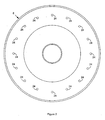
- Figure 2 is an end view of the inlet bell-mouth 8 that couples the inlet plenum 4 to the compressor 6 for the gas turbine engine 2 shown in Figure 1 .
- the inlet plenum 4 allows ambient air to pass through a plurality of inlet air apertures 10.
- a compressor shaft 12 rotates a compressor impeller 14 within a compressor shroud 16 to suck air within the inlet plenum 4 into a generally axial impeller inlet 18, compress it and discharge compressed air from a generally radial compressor outlet 20.
- a plurality of shroud-bleed apertures 22 penetrate through the compressor shroud 16 somewhat downstream of the impeller inlet 18 to allow a certain proportion of compressed air to escape from the compressor shroud 16.
- This compressed air normally recirculates back through the inlet plenum 4 by way of a plurality of bell-mouth apertures 24 that penetrates the bell-mouth 8.
- reverse air flow may flow from the inlet plenum 4 through the bell-mouth apertures 24 and into the shroud-bleed apertures 22.
- Such air flow entering through the shroud-bleed apertures 22 into compressor passages between blades of the compressor impeller 14 accelerates from virtually zero velocity to blade-tip velocity.
- Line 26 represents a possible path of typical particles that may find their way from the inlet plenum 2 into the shroud bleed apertures 22 in this manner.
- Figure 3 is a partial cut-away side view of a gas turbine engine 2 that has an inlet plenum 4 coupled to a compressor 6 by way of an inlet bell-mouth 28 according to a first possible embodiment of the invention.
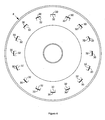
- Figure 4 is an end view of the inlet bell-mouth 28 that couples the inlet plenum 4 to the compressor 6 for the gas turbine engine 2 shown in Figure 3 according to a possible embodiment of the invention.
- the inlet bell-mouth 28 has a plurality of bell-mouth apertures 30.
- Each bell-mouth aperture 30 has an associated particle-deflecting baffle or louvre 32 along a compressor side 34 of the inlet bell-mouth 28.
- the apertures 30 have a generally rectangular shape.
- Each baffle 32 extends from the compressor side 34 of the inlet bell-mouth 28 to an outlet end 36.
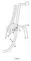
- FIG 5 is a partial cut-away side view of the inlet bell-mouth 28 that couples the inlet plenum 4 to the compressor 6 for the gas turbine engine 2 shown in Figure 3 that shows one of the bell-mouth apertures 30 with its associated baffle 32 in detail.
- Lines 38 represent streamlines of reverse air flow through the bell-mouth aperture 30 and associated baffle 32. Curvature of the streamlines 38 increases significantly as the acceleration of the reverse air flow increases from inside the inlet plenum 4 toward the bell-mouth aperture 30.
- the reverse air flow streamlines 38 penetrate the bell-mouth aperture 30 and bend around an inner surface 40 of the baffle 32 to a degree that any particle with a path that initially follows the reverse air flow, as represented by line 42, can no longer do so due to its inertia.
- the baffle 32 thereby forces the particlé out of the reverse air flow and it deflects off of the baffle 32 back into the inlet plenum 4 downstream of the inlet air apertures 10.
- the baffle 32 bends the reverse air flow to an extent that particles within the reverse airflow remain within the inlet plenum 4. It is possible to optimise the height H of the bell-mouth aperture 30, as represented by line 44, and the length L between the inlet side 34 of the inlet bell-mouth 28 and the outlet end 36 of the baffle 32, as represented by a line 46, to effectively eliminate ingestion of particles in this manner that are larger than a given size.
- each baffle 32 may have a generally rectangular or wedge-like shape that extends from the compressor side 34 of the inlet bell-mouth 28 to the outlet end 36 of the baffle 32, alternatively each baffle 32 may have different or more complex shapes that perform the same function.
- the inner surface 40 of each baffle 32 may be generally curvilinear rather than generally flat as shown in Figure 5 .
- Each bell-mouth aperture 30 may also have a variety of shapes, such as generally triangular or semicircular, in which case each associated baffle 32 may have a corresponding shape, such as a generally truncated cone or cup-like shape that extends from the compressor side 34 of the inlet bell-mouth 28.
- each baffle 32 may comprise a plurality of inner surfaces 40 that deflects particles in the reverse air flow stream back into the inlet plenum 4.
- Figure 6 is a partial cut-away side view of a gas turbine engine 2 that has an inlet plenum 4 coupled to a compressor 6 by way of an inlet bell-mouth 48 according to a second possible embodiment of the invention. It is similar in appearance to the inlet bell-mouth 28 shown in Figure 3 , but it has a plurality of bell-mouth apertures 50. Each bell-mouth aperture 50 has an associated particle-deflecting baffle or louvre 52 along an inlet side 54 of the inlet bell-mouth 48. In one possible embodiment the apertures 50 have a generally rectangular shape. Each baffle 52 extends from the inlet side 54 of the inlet bell-mouth 48 to an inlet end 56.
- Figure 7 is a partial cut-away side view of the inlet bell-mouth 48 that couples the inlet plenum to the compressor for the gas turbine engine shown in Figure 6 that shows one of the bell-mouth apertures 50 with its associated baffle 52 in detail.
- Lines 58 represent streamlines of reverse air flow through the bell-mouth aperture 50 and associated baffle 52. Curvature of the streamlines 58 increases significantly as the acceleration of the reverse air flow increases from inside the inlet plenum 4 toward the bell-mouth aperture 50.
- the reverse air flow streamlines 58 penetrate the bell-mouth aperture 50 and bend around an inner surface 60 of the baffle 52 to a degree that any particle with a path that initially follows the reverse air flow, as represented by line 62, can no longer do so due to its inertia.
- the baffle 52 thereby forces the particle out of the reverse air flow and it then continues its path within the inlet plenum 4.
- the baffle 52 bends the reverse air flow to an extent that particles within the reverse airflow remain within the inlet plenum 4.
- each baffle 52 may have a generally rectangular or wedge-like shape that extends from the inlet side 54 of the inlet bell-mouth 48 to the inlet end 56 of the baffle 52, alternatively each baffle 52 may have different or more complex shapes that perform the same function.
- the inner surface 60 of each baffle 52 may be generally curvilinear rather than generally flat as shown in Figure 7 .
- Each bell-mouth aperture 50 may also have a variety of shapes, such as generally triangular or semicircular, in which case each associated baffle 52 may have a corresponding shape, such as a generally truncated cone or cup-like shape that extends from the inlet side 54 of the inlet bell-mouth 48.
- each baffle 52 may comprise a plurality of inner surfaces 60 that separate particles out of the reverse air flow stream so that they remain within the inlet plenum 4.
- any embodiment of the invention such as the inlet bell-mouth 28 or the inlet bell-mouth 48 hereinbefore described, may comprise a stamping or weldment, such as of sheet metal, or a moulding, such as of plastic or a composite material.
- a stamping or weldment such as of sheet metal
- a moulding such as of plastic or a composite material.
Landscapes
- Engineering & Computer Science (AREA)
- Chemical & Material Sciences (AREA)
- Combustion & Propulsion (AREA)
- Mechanical Engineering (AREA)
- General Engineering & Computer Science (AREA)
- Structures Of Non-Positive Displacement Pumps (AREA)
- Supercharger (AREA)
Abstract
Description
- The invention relates to gas turbine engines, and more particularly to a gas turbine engine that has bleed slots arranged around its compressor shroud.
- Gas turbine engines for vehicles, such as helicopters and tanks, that operate in environments with significant particle loading due to atmospheric particulates, such as dust and sand, generally have an inlet design that employs an Inertial Particle Separator (IPS). Commercial aircraft do not generally operate in atmospheric conditions with high particle loading or concentration. Therefore, gas turbine engines for commercial aircraft, such as those employed as an auxiliary power unit (APU), generally do not include an IPS system since damage to the leading edges of their compressor blades due to ingestion of particles such as sand and dust is low.
- This is true as long as the compressor ingests airflow through its impeller/inducer inlet plane. In this case, the compressor continuously accelerates the airflow towards the impeller and then directs it through the flow passages in between the rotating blades. Consequently, if particle impact with the blades takes place in this context, impact angles are shallow and/or relative impact velocity is low.
- In order to increase operating range, many state-of-the-art gas turbine engines employed as an APU include an aerodynamic control feature referred to as "shroud bleed". A plurality of shroud-bleed apertures that each penetrate through the outer shroud for the compressor impeller somewhat downstream of the impeller throat allow a certain proportion of compressed air to escape from the compressor shroud and recirculate back through the engine inlet to improve the surge resistance of the compressor under heavy shaft loading conditions. This recirculated air passes through a plurality of bell-mouth apertures that penetrates a bell-mouth that couples the inlet plenum to the compressor. Under certain operating conditions, air flow may enter the compressor stage not only through the compressor inlet plane but also through the shroud-bleed apertures. Such air flow entering through the shroud-bleed apertures into the compressor passages between the impeller blades accelerates from virtually zero velocity to blade-tip velocity. Consequently, the bulk of any particles present within this reverse shroud-bleed air flow shall collide with the rotating impeller blade tips due to their inertia, thereby giving rise to blade erosion or damage.
- Generally, the invention comprises an IPS for an inlet bell-mouth that couples an inlet air plenum to a compressor in a gas turbine engine, wherein the IPS removes air particles within reverse air flow passing through at least one bell-mouth aperture in the inlet bell-mouth into shroud bleed apertures in a shroud for the compressor, comprising: at least one baffle that protrudes from each bell-mouth aperture positioned to bend a reverse air flow stream through the bell-mouth aperture to a degree that forces particles out of the reverse air flow stream and into the inlet air plenum.
- Preferred embodiments of the invention will now be described, by way of example only, and with reference to the accompanying drawings in which:
-
Figure 1 is a partial cut-away side view of a typical gas turbine engine that has an inlet plenum coupled to a compressor by way of an inlet bell-mouth according to the prior art. -
Figure 2 is an end view of the inlet bell-mouth that couples the inlet plenum to the compressor for the gas turbine engine shown inFigure 1 according to the prior art. -
Figure 3 is a partial cut-away side view of a gas turbine engine that has an inlet plenum coupled to a compressor by way of an inlet bell-mouth according to a first possible embodiment of the invention. -
Figure 4 is an end view of the inlet bell-mouth that couples the inlet plenum to the compressor for the gas turbine engine shown inFigure 3 according to a first possible embodiment of the invention. -
Figure 5 is a partial cut-away side view of the inlet bell-mouth that couples the inlet plenum to the compressor for the gas turbine engine shown inFigure 3 that shows a bell-mouth aperture for the inlet bell-mouth according to a first possible embodiment of the invention. -
Figure 6 is a partial cut-away side view of a gas turbine engine that has an inlet plenum coupled to a compressor by way of an inlet bell-mouth according to a second possible embodiment of the invention. -
Figure 7 is a partial cut-away side view of the inlet bell-mouth that couples the inlet plenum to the compressor for the gas turbine engine shown inFigure 6 that shows a bell-mouth aperture for the inlet bell-mouth according to a second possible embodiment of the invention. -
Figure 1 is a partial cut-away side view of a typicalgas turbine engine 2 that has aninlet plenum 4 coupled to acompressor 6 by way of an inlet bell-mouth 8 according to the prior art.Figure 2 is an end view of the inlet bell-mouth 8 that couples theinlet plenum 4 to thecompressor 6 for thegas turbine engine 2 shown inFigure 1 . Theinlet plenum 4 allows ambient air to pass through a plurality ofinlet air apertures 10. Acompressor shaft 12 rotates acompressor impeller 14 within acompressor shroud 16 to suck air within theinlet plenum 4 into a generallyaxial impeller inlet 18, compress it and discharge compressed air from a generallyradial compressor outlet 20. - A plurality of shroud-bleed
apertures 22 penetrate through thecompressor shroud 16 somewhat downstream of theimpeller inlet 18 to allow a certain proportion of compressed air to escape from thecompressor shroud 16. This compressed air normally recirculates back through theinlet plenum 4 by way of a plurality of bell-mouth apertures 24 that penetrates the bell-mouth 8. Under certain operating conditions, reverse air flow may flow from theinlet plenum 4 through the bell-mouth apertures 24 and into the shroud-bleedapertures 22. Such air flow entering through the shroud-bleedapertures 22 into compressor passages between blades of thecompressor impeller 14 accelerates from virtually zero velocity to blade-tip velocity. Consequently, the bulk of any particles present within this reverse shroud-bleed air flow will collide with rotating impeller blade tips of thecompressor impeller 14 due to particle inertia, thereby giving rise to blade erosion or damage of thecompressor impeller 14.Line 26 represents a possible path of typical particles that may find their way from theinlet plenum 2 into the shroud bleedapertures 22 in this manner. -
Figure 3 is a partial cut-away side view of agas turbine engine 2 that has aninlet plenum 4 coupled to acompressor 6 by way of an inlet bell-mouth 28 according to a first possible embodiment of the invention.Figure 4 is an end view of the inlet bell-mouth 28 that couples theinlet plenum 4 to thecompressor 6 for thegas turbine engine 2 shown inFigure 3 according to a possible embodiment of the invention. According to this embodiment, the inlet bell-mouth 28 has a plurality of bell-mouth apertures 30. Each bell-mouth aperture 30 has an associated particle-deflecting baffle or louvre 32 along acompressor side 34 of the inlet bell-mouth 28. In one possible embodiment theapertures 30 have a generally rectangular shape. Eachbaffle 32 extends from thecompressor side 34 of the inlet bell-mouth 28 to anoutlet end 36. -
Figure 5 is a partial cut-away side view of the inlet bell-mouth 28 that couples theinlet plenum 4 to thecompressor 6 for thegas turbine engine 2 shown inFigure 3 that shows one of the bell-mouth apertures 30 with itsassociated baffle 32 in detail.Lines 38 represent streamlines of reverse air flow through the bell-mouth aperture 30 and associatedbaffle 32. Curvature of thestreamlines 38 increases significantly as the acceleration of the reverse air flow increases from inside theinlet plenum 4 toward the bell-mouth aperture 30. The reverse air flow streamlines 38 penetrate the bell-mouth aperture 30 and bend around aninner surface 40 of thebaffle 32 to a degree that any particle with a path that initially follows the reverse air flow, as represented byline 42, can no longer do so due to its inertia. Thebaffle 32 thereby forces the particlé out of the reverse air flow and it deflects off of thebaffle 32 back into theinlet plenum 4 downstream of theinlet air apertures 10. - Thus, the
baffle 32 bends the reverse air flow to an extent that particles within the reverse airflow remain within theinlet plenum 4. It is possible to optimise the height H of the bell-mouth aperture 30, as represented byline 44, and the length L between theinlet side 34 of the inlet bell-mouth 28 and theoutlet end 36 of thebaffle 32, as represented by a line 46, to effectively eliminate ingestion of particles in this manner that are larger than a given size. - Although each
baffle 32 may have a generally rectangular or wedge-like shape that extends from thecompressor side 34 of the inlet bell-mouth 28 to theoutlet end 36 of thebaffle 32, alternatively eachbaffle 32 may have different or more complex shapes that perform the same function. For instance, theinner surface 40 of eachbaffle 32 may be generally curvilinear rather than generally flat as shown inFigure 5 . Each bell-mouth aperture 30 may also have a variety of shapes, such as generally triangular or semicircular, in which case each associatedbaffle 32 may have a corresponding shape, such as a generally truncated cone or cup-like shape that extends from thecompressor side 34 of the inlet bell-mouth 28. Finally, eachbaffle 32 may comprise a plurality ofinner surfaces 40 that deflects particles in the reverse air flow stream back into theinlet plenum 4. -
Figure 6 is a partial cut-away side view of agas turbine engine 2 that has aninlet plenum 4 coupled to acompressor 6 by way of an inlet bell-mouth 48 according to a second possible embodiment of the invention. It is similar in appearance to the inlet bell-mouth 28 shown inFigure 3 , but it has a plurality of bell-mouth apertures 50. Each bell-mouth aperture 50 has an associated particle-deflecting baffle or louvre 52 along aninlet side 54 of the inlet bell-mouth 48. In one possible embodiment theapertures 50 have a generally rectangular shape. Eachbaffle 52 extends from theinlet side 54 of the inlet bell-mouth 48 to aninlet end 56. -
Figure 7 is a partial cut-away side view of the inlet bell-mouth 48 that couples the inlet plenum to the compressor for the gas turbine engine shown inFigure 6 that shows one of the bell-mouth apertures 50 with itsassociated baffle 52 in detail.Lines 58 represent streamlines of reverse air flow through the bell-mouth aperture 50 and associatedbaffle 52. Curvature of thestreamlines 58 increases significantly as the acceleration of the reverse air flow increases from inside theinlet plenum 4 toward the bell-mouth aperture 50. The reverse air flow streamlines 58 penetrate the bell-mouth aperture 50 and bend around aninner surface 60 of thebaffle 52 to a degree that any particle with a path that initially follows the reverse air flow, as represented byline 62, can no longer do so due to its inertia. Thebaffle 52 thereby forces the particle out of the reverse air flow and it then continues its path within theinlet plenum 4. - Thus, the
baffle 52 bends the reverse air flow to an extent that particles within the reverse airflow remain within theinlet plenum 4. Again, it is possible to optimise the height H of the bell-mouth aperture 50, as represented byline 64, and the length L between theinlet side 54 of the inlet bell-mouth 48 and theinlet end 56 of thebaffle 52, as represented byline 66, to effectively eliminate ingestion of particles in this manner that are larger than a given size. - Once again, although each
baffle 52 may have a generally rectangular or wedge-like shape that extends from theinlet side 54 of the inlet bell-mouth 48 to theinlet end 56 of thebaffle 52, alternatively eachbaffle 52 may have different or more complex shapes that perform the same function. For instance, theinner surface 60 of eachbaffle 52 may be generally curvilinear rather than generally flat as shown inFigure 7 . Each bell-mouth aperture 50 may also have a variety of shapes, such as generally triangular or semicircular, in which case each associatedbaffle 52 may have a corresponding shape, such as a generally truncated cone or cup-like shape that extends from theinlet side 54 of the inlet bell-mouth 48. Finally, eachbaffle 52 may comprise a plurality ofinner surfaces 60 that separate particles out of the reverse air flow stream so that they remain within theinlet plenum 4. - Any embodiment of the invention, such as the inlet bell-
mouth 28 or the inlet bell-mouth 48 hereinbefore described, may comprise a stamping or weldment, such as of sheet metal, or a moulding, such as of plastic or a composite material. The described embodiments of the invention are only illustrative implementations of the invention wherein changes and substitutions of the various parts and arrangement thereof are within the scope of the invention as set forth in the attached claims.
Claims (26)
- An inertial particle separator (IPS) for an inlet bell-mouth (28, 48) that couples an inlet air plenum (4) to a compressor (6) in a gas turbine engine (2), wherein the inertial particle separator removes air particles within reverse air flow passing through at least one bell-mouth aperture (30, 50) in the inlet bell-mouth (28, 48) into shroud bleed apertures (22) in a shroud (16) for the compressor (6), comprising:at least one baffle (32, 52) that protrudes from each bell-mouth aperture (30, 50) positioned to bend a reverse air flow stream (38, 58) through the bell-mouth aperture (30, 50) to a degree that forces particles out of the reverse air flow stream (38, 58) and into the inlet air plenum (4).
- An inertial particle separator according to claim 1, wherein each baffle (52) protrudes from an inlet side of the bell-mouth (48).
- An inertial particle separator according to claim 1, wherein each baffle (32) protrudes from a compressor side of the bell-mouth (28).
- An inertial particle separator according to claim 3, wherein each bell-mouth aperture (30) has a height H and each associated baffle (32) has a length L between the compressor side of the inlet bell-mouth (28) and the outlet end (36) of the baffle (32), with the height H and the length L optimised to force particles out of the reverse air flow stream (38) and into the inlet air plenum (4) that are larger than a given size.
- An inertial particle separator according to claim 2, wherein each bell-mouth aperture (50) has a height H and each associated baffle (52) has a length L between an inlet side of the inlet bell-mouth (48) and an inlet end (56) of the baffle (52), with the height H and the length L optimised to force particles out of the reverse air flow stream (58) and into the inlet air plenum (4) that are larger than a given size.
- An inertial particle separator according to any preceding claim, wherein each bell-mouth aperture (30, 50) is generally rectangular and each associated baffle (32, 52) has a generally wedge-like shape.
- An inertial particle separator according to any of claims 1 to 5, wherein each bell-mouth aperture (30, 50) is generally triangular and each associated baffle (32, 52) has a generally truncated cone-like shape.
- An inertial particle separator according to any of claims 1 to 5, wherein each bell-mouth aperture (30, 50) is generally semicircular and each associated baffle (32, 52) has a generally cup-like shape.
- An inertial particle separator according to any of claims 1 to 8, wherein each inner surface (40, 60) of each baffle (32, 52) is generally flat.
- An inertial particle separator according to any of claims 1 to 8, wherein each inner surface (40, 60) of each baffle (32, 52) is generally curvilinear.
- An inertial particle separator according to any preceding claim, wherein each baffle (32, 52) has a plurality of the inner surfaces (40, 60).
- An inertial particle separator according to any preceding claim, wherein the compressor (6) has an impeller (14) with an axial throat (18), a radial outlet (20) and the shroud bleed apertures (22) are downstream from the axial throat (18).
- An air supply system for a gas turbine engine (2), comprising:an air compressor (6) for supplying compressed air to the engine (2) comprising a compressor shroud (16) that has a plurality of shroud bleed apertures (22);an inlet air plenum (4) that supplies air for the compressor (6);an inlet bell-mouth (28, 48) for coupling the inlet air plenum (4) to the compressor (6) that has a plurality of bell-mouth apertures (30, 50) to allow compressed air that bleeds from the shroud bleed apertures (22) to recirculate through the inlet air plenum (4) back into the compressor (6); andan inertial particle separator (IPS) comprising a plurality of baffles (32, 52) that protrude from the inlet bell-mouth (28, 48), each baffle (32, 52) associated with a corresponding bell-mouth aperture (30, 50) and having at least one inner surface (40, 60) positioned to bend a reverse air flow stream (38, 58) through its corresponding bell-mouth aperture (30, 50) to a degree that forces particles out of the reverse air flow stream (38, 58) and into the inlet air plenum (4).
- An air supply system according to claim 13, wherein each bell-mouth aperture (30) has a height H and each associated baffle (32) has a length L between a compressor side of the inlet bell-mouth (28) and an outlet end (36) of the baffle (32), with the height H and the length L optimised to force particles out of the reverse air flow stream (38) and into the inlet air plenum (4) that are larger than a given size.
- An air supply system according to claim 13, wherein each bell-mouth aperture (50) has a height H and each associated baffle has a length L between an inlet side of the inlet bell-mouth (48) and an inlet end (56) of the baffle (52), with the height H and the length L optimised to force particles out of the reverse air flow stream (58) and into the inlet air plenum (4) that are larger than a given size.
- An air supply system according to any of claims 13 to 15, wherein each bell-mouth aperture (30, 50) is generally rectangular and each associated baffle (32, 52) has a generally wedge-like shape.
- An air supply system according to any of claims 13 to 15, wherein each bell-mouth aperture (30, 50) is generally triangular and each associated baffle (32, 52) has a generally truncated cone-like shape.
- An air supply system according to any of claims 13 to 15, wherein each bell-mouth aperture (30, 50) is generally semicircular and each associated baffle (32, 52) has a generally cup-like shape.
- An air supply system according to any of claims 13 to 18, wherein each inner surface (40, 60) of each baffle (32, 52) is generally flat.
- An air supply system according to any of claims 13 to 18, wherein each inner surface (40, 60) of each baffle (32, 52) is generally curvilinear.
- An air supply system according to any of claims 13 to 20, wherein each baffle (32, 52) has a plurality of the inner surfaces (40).
- An air supply system according to any of claims 13 to 21, wherein the compressor (6) has an impeller (14) with an axial throat (18), a radial outlet (20) and the shroud bleed apertures (22) are downstream from the axial throat (18).
- A gas turbine engine (2) comprising:an air compressor (6) for supplying compressed air to the engine (2) comprising a compressor shroud (16) that has a plurality of shroud bleed apertures (22);an inlet air plenum (4) that supplies air for the compressor (6);an inlet bell-mouth (28, 48) for coupling the inlet air plenum (4) to the compressor (6) that has a plurality of bell-mouth apertures (30, 50) to allow compressed air that bleeds from the shroud bleed apertures (22) to recirculate through the inlet air plenum (4) back into the compressor (6); andan inertial particle separator (IPS) comprising a plurality of baffles (32, 52) that protrude from the inlet bell-mouth (28, 48), each baffle (32, 52) associated with a corresponding bell-mouth aperture (30, 50) and having at least one inner surface (40, 60) positioned to bend a reverse air flow stream (38, 58) to a degree that forces particles out of the reverse air flow stream (38, 58) and into the inlet air plenum (4).
- A gas turbine engine according to claim 23, wherein each bell-mouth aperture (30) has a height H and each associated baffle (32) has a length L between a compressor side of the inlet bell-mouth (28) and an outlet end (36) of the baffle (32), with the height H and the length L optimised to force particles out of the reverse air flow stream (38) and into the inlet air plenum (4) that are larger than a given size.
- A gas turbine engine according to claim 23, wherein each bell-mouth aperture (50) has a height H and each associated baffle (52) has a length L between an inlet side of the inlet bell-mouth (48) and an inlet end (56) of the baffle (52), with the height H and the length L optimized to force particles out of the reverse air flow stream (58) and into the inlet air plenum (4) that are larger than a given size.
- A gas turbine engine according to claim 23, 24 or 25, wherein the compressor (6) has an impeller (14) with an axial throat (18), a radial outlet (20) and the shroud bleed apertures (22) are downstream from the axial throat (18).
Applications Claiming Priority (1)
| Application Number | Priority Date | Filing Date | Title |
|---|---|---|---|
| US11/642,493 US20080152500A1 (en) | 2006-12-20 | 2006-12-20 | Inertial particle separator for compressor shroud bleed |
Publications (3)
| Publication Number | Publication Date |
|---|---|
| EP1939460A2 true EP1939460A2 (en) | 2008-07-02 |
| EP1939460A3 EP1939460A3 (en) | 2011-05-25 |
| EP1939460B1 EP1939460B1 (en) | 2014-12-17 |
Family
ID=39111034
Family Applications (1)
| Application Number | Title | Priority Date | Filing Date |
|---|---|---|---|
| EP07254628.6A Ceased EP1939460B1 (en) | 2006-12-20 | 2007-11-29 | Intertial particle separator for compressor shroud bleed |
Country Status (4)
| Country | Link |
|---|---|
| US (1) | US20080152500A1 (en) |
| EP (1) | EP1939460B1 (en) |
| BR (1) | BRPI0704853B1 (en) |
| CA (1) | CA2606854C (en) |
Families Citing this family (14)
| Publication number | Priority date | Publication date | Assignee | Title |
|---|---|---|---|---|
| US20090201639A1 (en) * | 2008-02-12 | 2009-08-13 | Inventec Corporation | Chassis of portable electronic apparatus |
| US8092145B2 (en) * | 2008-10-28 | 2012-01-10 | Pratt & Whitney Canada Corp. | Particle separator and separating method for gas turbine engine |
| US7922784B2 (en) * | 2009-03-23 | 2011-04-12 | King Fahd University Of Petroleum And Minerals | System for inertial particles separation |
| US8945254B2 (en) | 2011-12-21 | 2015-02-03 | General Electric Company | Gas turbine engine particle separator |
| US9677472B2 (en) * | 2012-10-08 | 2017-06-13 | United Technologies Corporation | Bleed air slot |
| US9719352B2 (en) | 2014-12-17 | 2017-08-01 | Honeywell International Inc. | Compartment based inlet particle separator system |
| US10227930B2 (en) | 2016-03-28 | 2019-03-12 | General Electric Company | Compressor bleed systems in turbomachines and methods of extracting compressor airflow |
| US10208628B2 (en) | 2016-03-30 | 2019-02-19 | Honeywell International Inc. | Turbine engine designs for improved fine particle separation efficiency |
| US10787920B2 (en) | 2016-10-12 | 2020-09-29 | General Electric Company | Turbine engine inducer assembly |
| US20180135516A1 (en) | 2016-11-16 | 2018-05-17 | Honeywell International Inc. | Scavenge methodologies for turbine engine particle separation concepts |
| US10816014B2 (en) | 2018-07-25 | 2020-10-27 | Honeywell International Inc. | Systems and methods for turbine engine particle separation |
| US11674527B2 (en) * | 2020-06-08 | 2023-06-13 | Honeywell International Inc. | Compressor ported shroud with particle separator |
| US12060891B2 (en) * | 2021-10-25 | 2024-08-13 | Pratt & Whitney Canada Corp. | Centrifugal compressor having a bellmouth with a stiffening member |
| US20250257689A1 (en) * | 2024-02-08 | 2025-08-14 | Pratt & Whitney Canada Corp. | Bleed-off assembly intake device for an aircraft propulsion system |
Citations (1)
| Publication number | Priority date | Publication date | Assignee | Title |
|---|---|---|---|---|
| US6499285B1 (en) | 2001-08-01 | 2002-12-31 | Rolls-Royce Corporation | Particle separator for a gas turbine engine |
Family Cites Families (6)
| Publication number | Priority date | Publication date | Assignee | Title |
|---|---|---|---|---|
| US3329377A (en) * | 1965-10-11 | 1967-07-04 | United Aircraft Canada | Protection for aircraft engines against snow, ice and airborne particles |
| US4004760A (en) * | 1975-03-25 | 1977-01-25 | Mitsubishi Jukogyo Kabushiki Kaisha | Device for preventing foreign matters from being sucked into a gas turbine engine for an aircraft |
| US4860534A (en) * | 1988-08-24 | 1989-08-29 | General Motors Corporation | Inlet particle separator with anti-icing means |
| US4981018A (en) * | 1989-05-18 | 1991-01-01 | Sundstrand Corporation | Compressor shroud air bleed passages |
| US5295785A (en) * | 1992-12-23 | 1994-03-22 | Caterpillar Inc. | Turbocharger having reduced noise emissions |
| US6134874A (en) * | 1998-06-02 | 2000-10-24 | Pratt & Whitney Canada Corp. | Integral inertial particle separator for radial inlet gas turbine engine |
-
2006
- 2006-12-20 US US11/642,493 patent/US20080152500A1/en not_active Abandoned
-
2007
- 2007-10-12 CA CA2606854A patent/CA2606854C/en not_active Expired - Fee Related
- 2007-11-29 EP EP07254628.6A patent/EP1939460B1/en not_active Ceased
- 2007-12-18 BR BRPI0704853A patent/BRPI0704853B1/en not_active IP Right Cessation
Patent Citations (1)
| Publication number | Priority date | Publication date | Assignee | Title |
|---|---|---|---|---|
| US6499285B1 (en) | 2001-08-01 | 2002-12-31 | Rolls-Royce Corporation | Particle separator for a gas turbine engine |
Also Published As
| Publication number | Publication date |
|---|---|
| BRPI0704853A (en) | 2008-08-12 |
| US20080152500A1 (en) | 2008-06-26 |
| EP1939460B1 (en) | 2014-12-17 |
| BRPI0704853A8 (en) | 2018-06-19 |
| CA2606854A1 (en) | 2008-06-20 |
| CA2606854C (en) | 2013-01-08 |
| BRPI0704853B1 (en) | 2019-01-15 |
| EP1939460A3 (en) | 2011-05-25 |
Similar Documents
| Publication | Publication Date | Title |
|---|---|---|
| CA2606854C (en) | Inertial particle separator for compressor shroud bleed | |
| US6134874A (en) | Integral inertial particle separator for radial inlet gas turbine engine | |
| EP0497574B1 (en) | Fan case treatment | |
| JP6111040B2 (en) | Gas turbine engine particle separator | |
| EP1818511A2 (en) | Leaned deswirl vanes behind a centrifugal compressor in a gas turbine engine | |
| EP0743247A2 (en) | Passive cooling device and method for cooling an auxiliary power unit on an airoplane | |
| EP1793086A2 (en) | Turbine blade | |
| CN113417891B (en) | Centrifugal compressor anti-icing air entraining structure and engine | |
| US20110318188A1 (en) | Axial centrifugal compressor with scalable rake angle | |
| EP3260687A1 (en) | Inlet particle separator system with pre-cleaner flow passage | |
| EP3074612B1 (en) | Turbomachinery inlet screen | |
| US20220275733A1 (en) | Ejector driven scavenge system for particle separator associated with gas turbine engine | |
| EP2737933A1 (en) | Inlet particle separator system with air injection | |
| EP4001616B1 (en) | Asymmetric inlet particle separator for gas turbine engine | |
| CA2965375A1 (en) | Film cooled engine component for a gas turbine engine | |
| KR20120034670A (en) | Centrifugal impeller for compressor | |
| JP2004506141A (en) | Centrifugal fan | |
| CN112412873B (en) | Impeller with chord-wise blade thickness variation | |
| EP3467289B1 (en) | A gas turbine engine and air intake assembly | |
| EP1411248A1 (en) | IMPELLER OF CENTRIFUGAL BLOWER, AND CENTRIFUGAL BLOWER HAVING THE IMPELLER | |
| EP3922861A1 (en) | Compressor ported shroud with particle separator | |
| CN107850081B (en) | Turbofan and the air-conditioning for having used the turbofan | |
| RU2792505C2 (en) | Gas turbine engine blade made according to the rule of deflection of the blade profile with a large flutter margin | |
| KR20110083363A (en) | Impeller and compressor | |
| RU2794951C2 (en) | Gas turbine engine blade with maximum thickness rule with high flutter strength |
Legal Events
| Date | Code | Title | Description |
|---|---|---|---|
| PUAI | Public reference made under article 153(3) epc to a published international application that has entered the european phase |
Free format text: ORIGINAL CODE: 0009012 |
|
| AK | Designated contracting states |
Kind code of ref document: A2 Designated state(s): AT BE BG CH CY CZ DE DK EE ES FI FR GB GR HU IE IS IT LI LT LU LV MC MT NL PL PT RO SE SI SK TR |
|
| AX | Request for extension of the european patent |
Extension state: AL BA HR MK RS |
|
| PUAL | Search report despatched |
Free format text: ORIGINAL CODE: 0009013 |
|
| AK | Designated contracting states |
Kind code of ref document: A3 Designated state(s): AT BE BG CH CY CZ DE DK EE ES FI FR GB GR HU IE IS IT LI LT LU LV MC MT NL PL PT RO SE SI SK TR |
|
| AX | Request for extension of the european patent |
Extension state: AL BA HR MK RS |
|
| RIC1 | Information provided on ipc code assigned before grant |
Ipc: F02C 7/052 20060101ALI20110421BHEP Ipc: F04D 29/70 20060101AFI20080305BHEP Ipc: B64C 7/02 20060101ALI20110421BHEP |
|
| 17P | Request for examination filed |
Effective date: 20111116 |
|
| AKX | Designation fees paid |
Designated state(s): FR |
|
| REG | Reference to a national code |
Ref country code: DE Ref legal event code: R108 |
|
| REG | Reference to a national code |
Ref country code: DE Ref legal event code: R108 Effective date: 20120201 |
|
| GRAP | Despatch of communication of intention to grant a patent |
Free format text: ORIGINAL CODE: EPIDOSNIGR1 |
|
| INTG | Intention to grant announced |
Effective date: 20140902 |
|
| GRAS | Grant fee paid |
Free format text: ORIGINAL CODE: EPIDOSNIGR3 |
|
| GRAA | (expected) grant |
Free format text: ORIGINAL CODE: 0009210 |
|
| AK | Designated contracting states |
Kind code of ref document: B1 Designated state(s): FR |
|
| PLBE | No opposition filed within time limit |
Free format text: ORIGINAL CODE: 0009261 |
|
| REG | Reference to a national code |
Ref country code: FR Ref legal event code: PLFP Year of fee payment: 9 |
|
| STAA | Information on the status of an ep patent application or granted ep patent |
Free format text: STATUS: NO OPPOSITION FILED WITHIN TIME LIMIT |
|
| 26N | No opposition filed |
Effective date: 20150918 |
|
| REG | Reference to a national code |
Ref country code: FR Ref legal event code: PLFP Year of fee payment: 10 |
|
| REG | Reference to a national code |
Ref country code: FR Ref legal event code: PLFP Year of fee payment: 11 |
|
| REG | Reference to a national code |
Ref country code: FR Ref legal event code: PLFP Year of fee payment: 12 |
|
| PGFP | Annual fee paid to national office [announced via postgrant information from national office to epo] |
Ref country code: FR Payment date: 20181024 Year of fee payment: 12 |
|
| PG25 | Lapsed in a contracting state [announced via postgrant information from national office to epo] |
Ref country code: FR Free format text: LAPSE BECAUSE OF NON-PAYMENT OF DUE FEES Effective date: 20191130 |