EP1939445A2 - Method for predicting a power curve for a wind turbine - Google Patents
Method for predicting a power curve for a wind turbine Download PDFInfo
- Publication number
- EP1939445A2 EP1939445A2 EP07121834A EP07121834A EP1939445A2 EP 1939445 A2 EP1939445 A2 EP 1939445A2 EP 07121834 A EP07121834 A EP 07121834A EP 07121834 A EP07121834 A EP 07121834A EP 1939445 A2 EP1939445 A2 EP 1939445A2
- Authority
- EP
- European Patent Office
- Prior art keywords
- power
- curve
- wind turbine
- power curve
- wind
- Prior art date
- Legal status (The legal status is an assumption and is not a legal conclusion. Google has not performed a legal analysis and makes no representation as to the accuracy of the status listed.)
- Granted
Links
- 238000000034 method Methods 0.000 title claims abstract description 69
- 238000011217 control strategy Methods 0.000 claims description 13
- 238000010586 diagram Methods 0.000 description 8
- 238000010606 normalization Methods 0.000 description 5
- 230000001276 controlling effect Effects 0.000 description 4
- 238000004519 manufacturing process Methods 0.000 description 4
- 238000009826 distribution Methods 0.000 description 3
- 230000004048 modification Effects 0.000 description 2
- 238000012986 modification Methods 0.000 description 2
- 230000001105 regulatory effect Effects 0.000 description 2
- 238000010561 standard procedure Methods 0.000 description 2
- 230000002411 adverse Effects 0.000 description 1
- 230000008859 change Effects 0.000 description 1
- 238000012512 characterization method Methods 0.000 description 1
- 230000007423 decrease Effects 0.000 description 1
- 230000001419 dependent effect Effects 0.000 description 1
- 230000006870 function Effects 0.000 description 1
- 230000006872 improvement Effects 0.000 description 1
Images


Classifications
-
- F—MECHANICAL ENGINEERING; LIGHTING; HEATING; WEAPONS; BLASTING
- F03—MACHINES OR ENGINES FOR LIQUIDS; WIND, SPRING, OR WEIGHT MOTORS; PRODUCING MECHANICAL POWER OR A REACTIVE PROPULSIVE THRUST, NOT OTHERWISE PROVIDED FOR
- F03D—WIND MOTORS
- F03D7/00—Controlling wind motors
- F03D7/02—Controlling wind motors the wind motors having rotation axis substantially parallel to the air flow entering the rotor
- F03D7/04—Automatic control; Regulation
- F03D7/042—Automatic control; Regulation by means of an electrical or electronic controller
-
- F—MECHANICAL ENGINEERING; LIGHTING; HEATING; WEAPONS; BLASTING
- F03—MACHINES OR ENGINES FOR LIQUIDS; WIND, SPRING, OR WEIGHT MOTORS; PRODUCING MECHANICAL POWER OR A REACTIVE PROPULSIVE THRUST, NOT OTHERWISE PROVIDED FOR
- F03D—WIND MOTORS
- F03D17/00—Monitoring or testing of wind motors, e.g. diagnostics
-
- F—MECHANICAL ENGINEERING; LIGHTING; HEATING; WEAPONS; BLASTING
- F03—MACHINES OR ENGINES FOR LIQUIDS; WIND, SPRING, OR WEIGHT MOTORS; PRODUCING MECHANICAL POWER OR A REACTIVE PROPULSIVE THRUST, NOT OTHERWISE PROVIDED FOR
- F03D—WIND MOTORS
- F03D7/00—Controlling wind motors
- F03D7/02—Controlling wind motors the wind motors having rotation axis substantially parallel to the air flow entering the rotor
- F03D7/028—Controlling wind motors the wind motors having rotation axis substantially parallel to the air flow entering the rotor controlling wind motor output power
-
- F—MECHANICAL ENGINEERING; LIGHTING; HEATING; WEAPONS; BLASTING
- F05—INDEXING SCHEMES RELATING TO ENGINES OR PUMPS IN VARIOUS SUBCLASSES OF CLASSES F01-F04
- F05B—INDEXING SCHEME RELATING TO WIND, SPRING, WEIGHT, INERTIA OR LIKE MOTORS, TO MACHINES OR ENGINES FOR LIQUIDS COVERED BY SUBCLASSES F03B, F03D AND F03G
- F05B2270/00—Control
- F05B2270/10—Purpose of the control system
- F05B2270/103—Purpose of the control system to affect the output of the engine
- F05B2270/1033—Power (if explicitly mentioned)
-
- F—MECHANICAL ENGINEERING; LIGHTING; HEATING; WEAPONS; BLASTING
- F05—INDEXING SCHEMES RELATING TO ENGINES OR PUMPS IN VARIOUS SUBCLASSES OF CLASSES F01-F04
- F05B—INDEXING SCHEME RELATING TO WIND, SPRING, WEIGHT, INERTIA OR LIKE MOTORS, TO MACHINES OR ENGINES FOR LIQUIDS COVERED BY SUBCLASSES F03B, F03D AND F03G
- F05B2270/00—Control
- F05B2270/30—Control parameters, e.g. input parameters
- F05B2270/324—Air pressure
-
- F—MECHANICAL ENGINEERING; LIGHTING; HEATING; WEAPONS; BLASTING
- F05—INDEXING SCHEMES RELATING TO ENGINES OR PUMPS IN VARIOUS SUBCLASSES OF CLASSES F01-F04
- F05B—INDEXING SCHEME RELATING TO WIND, SPRING, WEIGHT, INERTIA OR LIKE MOTORS, TO MACHINES OR ENGINES FOR LIQUIDS COVERED BY SUBCLASSES F03B, F03D AND F03G
- F05B2270/00—Control
- F05B2270/30—Control parameters, e.g. input parameters
- F05B2270/335—Output power or torque
-
- F—MECHANICAL ENGINEERING; LIGHTING; HEATING; WEAPONS; BLASTING
- F05—INDEXING SCHEMES RELATING TO ENGINES OR PUMPS IN VARIOUS SUBCLASSES OF CLASSES F01-F04
- F05B—INDEXING SCHEME RELATING TO WIND, SPRING, WEIGHT, INERTIA OR LIKE MOTORS, TO MACHINES OR ENGINES FOR LIQUIDS COVERED BY SUBCLASSES F03B, F03D AND F03G
- F05B2270/00—Control
- F05B2270/80—Devices generating input signals, e.g. transducers, sensors, cameras or strain gauges
- F05B2270/802—Calibration thereof
-
- Y—GENERAL TAGGING OF NEW TECHNOLOGICAL DEVELOPMENTS; GENERAL TAGGING OF CROSS-SECTIONAL TECHNOLOGIES SPANNING OVER SEVERAL SECTIONS OF THE IPC; TECHNICAL SUBJECTS COVERED BY FORMER USPC CROSS-REFERENCE ART COLLECTIONS [XRACs] AND DIGESTS
- Y02—TECHNOLOGIES OR APPLICATIONS FOR MITIGATION OR ADAPTATION AGAINST CLIMATE CHANGE
- Y02E—REDUCTION OF GREENHOUSE GAS [GHG] EMISSIONS, RELATED TO ENERGY GENERATION, TRANSMISSION OR DISTRIBUTION
- Y02E10/00—Energy generation through renewable energy sources
- Y02E10/70—Wind energy
- Y02E10/72—Wind turbines with rotation axis in wind direction
Definitions
- the present invention relates to a method for predicting a power curve for a wind turbine, especially to a method for obtaining a power curve adapted for high altitude operation of a wind turbine. Furthermore, the present invention is directed to a control strategy utilizing such power curve and to a wind turbine in which such control strategy is implemented.
- Wind turbines capture kinetic energy from the wind and convert it into electrical power. Since wind turbines can be designed as stand-alone or island solutions, they are especially suited to supply electric power to remote areas. For example, such areas may be located in mountainous regions or elevated plains, i.e. at high altitude. Due to their elevated location, wind turbines installed at those sites encounter a lower air density compared to sea level. The lower air density causes significant deviations from the "normal" operation at sea level. In particular, the power curve of the wind turbines is different for operation in high altitude. Since the power curve is used to predict the annual power output of the turbines, the power curve deviation may adversely affect the quality of power output predictions. Also, the power curve is used as a basis for the control strategy implemented in the turbine controller. Accordingly, turbine control will not be optimal if the implemented power curve does not correctly reflect the actual behavior of the turbine.
- the IEC standard describes a method how the sea level power curve of a pitch-regulated wind turbine can be corrected for lower air density at high-altitude sites.
- the power curves corrected according to standard IEC 61400-12, edition 1998 do not correctly reflect the turbine behavior and, typically, overrate the power production in the partial load operation range of the wind turbine.
- a method for obtaining a power curve for a wind turbine includes the steps of determining a relation between the power coefficient c p and the tip-speed ratio ⁇ for said wind turbine, and using the relation between power coefficient c p and the tip-speed ratio ⁇ to determine a relation between the electrical power output P and wind speed v to obtain the power curve.
- a method for obtaining a power curve for a wind turbine is provided.
- a dependency of the power coefficient on the tip-speed ratio for said wind turbine is identified.
- the identified dependency of the power coefficient is then used to calculate a relation between the electrical power output and wind speed to obtain the power curve for said wind turbine.
- the variation of the power coefficient depending on a change of the tip speed ratio is taken into consideration.
- the assumption of a constant power coefficient is abandoned and the power curve of the wind turbine is calculated on the basis of a varying power coefficient.
- the power curve obtained by the above-described method reflects the actual power curve measured in the field much better than a corrected power curve obtained according to the IEC 61400-12 standard.
- the quality of annual power output predictions as well as turbine control can be considerably improved.
- a method for calculating a high-altitude power curve for a wind turbine includes the steps of determining a c p - ⁇ curve for a predetermined blade pitch angle of said wind turbine; calculating a first power curve without power limit based on the c p - ⁇ curve; and calculating the high-altitude power curve with power limit from said first power curve, thereby using a site air density.
- a method of controlling the operation of a wind turbine includes the steps of, in an upper partial load range of said wind turbine, using a control strategy based on a corrected power curve which has been obtained by determining a c p - ⁇ curve for a predetermined blade pitch angle of said wind turbine; calculating a first power curve without power limit based on the c p - ⁇ curve; and calculating the corrected power curve with power limit from said first power curve, thereby using a site air density.
- Fig. 1 shows a flow diagram of a method according to a first embodiment of the present invention.
- Fig. 2 shows a flow diagram of a method according to a further embodiment of the present invention.
- Fig. 3 shows a flow diagram of a method according to another embodiment of the present invention.
- Fig. 4 shows c p - ⁇ curves as they are used in the embodiments of the present invention.
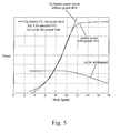
- Fig. 5 shows power curves with and without power limit as they are used in embodiments of the present invention.
- Fig. 6 shows a comparison of a power curve obtained by a method according to an embodiment of the present invention and a power curve obtained by a standard high-altitude correction procedure.
- Fig. 7 shows an enlarged view of a deviation in Fig. 6 .
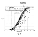
- Fig. 8 shows a comparison of a power curve obtained by a method according to an embodiment of the present invention and a power curve obtained by a standard procedure to measured power output values.
- Fig. 9 shows a comparison of a power curve obtained by a method according to an embodiment of the present invention and a power curve obtained by a standard procedure for sea level air density.
- Fig. 10 shows a control scheme for a wind turbine according to an embodiment of the present invention.
- Fig. 11 shows a flow diagram of a control method according to a further embodiment of the present invention.
- Fig. 1 shows a flow diagram of a method according to a first embodiment of the present invention.
- a relation between the power coefficient c p and the tip-speed ratio ⁇ is determined.
- This relation is typically called a c p - ⁇ curve and is widely used for the characterization of wind turbines.
- the c p - ⁇ curve will depend on the shape and number of the rotor blades as well as on the actual pitch angle of the blades.
- Fig. 4 shows several examples of c p - ⁇ curves for different values of the pitch angle ⁇ .
- the power coefficient c p varies with tip speed ratio ⁇ and has a well-defined maximum value. It can be seen from Fig. 4 that the position and height of the maximum c p changes substantially with pitch angle ⁇ .
- the relation between power coefficient c p and tip-speed ratio ⁇ is used to determine a relation between the electrical power output P and wind speed v.
- This relation between power output and wind speed is also called the power curve of the turbine and is well-known to those skilled in the art.
- An example of a power curve is shown in Fig. 5 .
- the curve labeled "power curve with power limit" is a standard power curve for a pitch regulated wind turbine. It can be seen that the maximum power output is constant independent of the wind speed. This is the so-called full load region of operation at wind speeds of about 13 m/s or more where the wind turbine constantly generates its maximum output power.
- the wind turbine is in the so-called partial load region.
- the power production in the partial load region is not constant and varies depending on wind speed.
- the power curve is determined in step 102 using on the c p - ⁇ curve determined in previous step 101.
- the variation of power coefficient c p with tip speed ratio ⁇ ( Fig. 4 ) is taken into account when determining the power curve. Accordingly, the power curve determined by the above-described method is more exact than a power curve which does not take the variation of power coefficient c p into account.
- v n v 10 ⁇ min ⁇ ⁇ 10 ⁇ min ⁇ 0 / 3 1
- v n normalized wind speed
- ⁇ 0 reference air density (sea level)
- v 10min measured wind speed averaged over 10 minutes
- ⁇ 10min measured air density averaged over 10 minutes.
- the power curve obtained by a method according to an embodiment of the present invention takes the variation of c p with tip speed ⁇ into account
- the power curve according to the present invention reflects the actual power production of the wind turbine more accurately compared to the power curve obtained by the IEC normalization method. This is shown in Figs. 6 and 7 , where a c p -based power curve and an IEC adjusted power curve for high altitude conditions are plotted together. It can be seen that there exists a considerable deviation between the two power curves in an upper partial load range from about 10 m/s to about 13 m/s. This region is shown in an enlarged view in Fig. 7 .
- the IEC adjusted power curve overrates the output power in the upper partial load range compared to the c p -based power curve.
- a comparison of the IEC adjusted power curve and the c p -based power curve with measured power values at a high altitude site is shown in Fig. 8 .
- the c p -based power curve fits the measured values much better in the upper partial load range than the IEC adjusted curve. Therefore, the power curve obtained by a method according to an embodiment of the present invention is better adapted to the actual power production of the turbines than the IEC adjusted power curve. This improvement is especially relevant for high altitude sites as shown in Figs. 6, 7 , and 8 .
- the cp-based power curve is adapted for low air density sites, i.e. high altitude and low air density may be used synonymously.
- Fig. 9 shows a comparison of a c p -based power curve obtained by a method according to an embodiment of the present invention and an IEC adjusted power curve, wherein the results are obtained for sea level.
- the power curves are substantially identical, i.e. both methods lead to almost identical results at sea level.
- Fig. 2 shows a flow diagram of a method according to a further embodiment of the present invention.
- a fixed pitch angle ⁇ is determined in a first step 201.
- a power curve is calculated taking into account the c p variation. This can be either done directly or by first converting the c p - ⁇ curve into a c p -v curve, i.e. by first determining the relation between power coefficient and wind speed from the c p - ⁇ curve.
- a typical c p -v curve is shown in Fig. 5 from which is apparent that c p is more or less constant in a lower partial load range but decreases within an upper partial load range, i.e. above about 8 m/s.
- a power curve without power limit is calculated. Such a power curve without limit is also shown in Fig. 5 .
- a power curve having a power limit is calculated from the intermediate unlimited power curve in final step 204.
- the air density at the wind turbine site is taken into account.
- the present method is applied to calculate power curves for turbine at high altitude sites. At those sites, the local air density typically is only 80% to 95 %, more typically 80% to 90% of the air density at sea level.
- a power curve for a high altitude site having an air density as low as 1.02 kg/m 3 (compared to 1.225 kg/m 3 at sea level) is calculated.
- a power curve is obtained that is suitably fitted to the actual output power of the wind turbine.
- the power curve obtained by the above method fits the actual output power better than an IEC adjusted power curve as is shown in Fig. 8 .
- Fig. 3 shows a flow diagram of a method according to another embodiment of the present invention. Therein, it is described how the calculated power curve can be smoothed and atmospheric turbulence can be taken into account.
- first N sample wind speed values, N ⁇ 1 are determined in step 301.
- the power curve is to be calculated in the wind speed range between 7 m/s and 16 m/s.
- the N sample wind speed values may then be determined by dividing the wind speed range into N-1 regular intervals. Of course, the sample values may also be determined by any other suitable method.
- a first sample value is selected and a set of M randomly distributed wind speed values is generated in step 302.
- the wind speed values are distributed according to a normal distribution centered about the sample value. However, other distributions may be chosen if they are believed to resemble the wind speed variations more closely.
- the corresponding output power value is calculated for each of the randomly distributed wind speed values, thereby using the c p - ⁇ curve as described above.
- the wind speeds and the power values are averaged to obtain a mean wind speed value and a mean output power value. This procedure is repeated for any of the N sample wind speed values so that the power curve is smoothed by the averaged values. After the averaged output power and wind speed values have been obtained, the method continues with the calculation of the power curve with power limit in step 204.
- Fig. 10 shows a control scheme for a wind turbine according to an embodiment of the present invention.
- generator torque vs. generator speed is shown and different control stages are marked by literals A to D.
- the cut-in stage A-B the wind speed attains the minimum level for turbine operation and the turbine cuts in for operation.
- the wind turbine control is limited since the turbine cannot capture maximum energy due to the physical limitation itself.
- generator speed is kept constant and controlled via the torque, i.e. via the electric system of the generator.
- the lower partial load range with typical wind speeds in the range of about 4 m/s to 8 m/s.
- generator speed increases and the turbine is running with optimum c p so that maximum energy is captured from the wind.
- the upper partial load range begins, typically in a wind speed range from about 8 m/s up to about 13 m/s.
- the generator speed is kept constant at the rated generator speed while generator torque increases up to the rated torque.
- the pitch angle ⁇ is fixed and generator speed is controlled via torque as in stage A-B. Above rated torque, full load operation and overload operation of the turbine occurs wherein generator speed is controlled via the blade pitch.
- Fig. 11 shows a flow diagram of a control method according to a further embodiment of the present invention.
- step 1101 it is first determined in step 1101 whether the turbine operates in an upper partial load range, typically in a wind speed range of about 8 m/s to about 13 m/s. If not, a different control strategy, e.g. as described above, is applied. If the turbine operates in the upper partial load range, a power curve based on a c p - ⁇ curve for the predetermined pitch angle ⁇ is obtained. Typically, the pitch angle ⁇ and the power curve will be previously calculated and stored in a memory of the wind turbine controller, e.g. in the form of a list.
- the pitch angle ⁇ is kept constant, e.g. at 2°, in step 1103.
- the generator speed is kept constant, typically at the rated generator speed, in step 1104. Typically, this is done by controlling generator speed via generator torque. Since the above-described control strategy uses the c p -based power curve for generator control, it is better adapted than a control strategy based on an IEC adjusted power curve.
- the present invention includes a wind turbine having a wind turbine controlled in which a control strategy according to an embodiment of the present invention is implemented.
- a c p -based power curve may be stored in the turbine controller, e.g. as a functional relationship or a list. Since the c p -based power curve is well adapted to the actual power output, especially at high altitude sites, the turbine controller is improved compared to turbine controllers using an IEC adjusted power curve.
Abstract
Description
- The present invention relates to a method for predicting a power curve for a wind turbine, especially to a method for obtaining a power curve adapted for high altitude operation of a wind turbine. Furthermore, the present invention is directed to a control strategy utilizing such power curve and to a wind turbine in which such control strategy is implemented.
- Wind turbines capture kinetic energy from the wind and convert it into electrical power. Since wind turbines can be designed as stand-alone or island solutions, they are especially suited to supply electric power to remote areas. For example, such areas may be located in mountainous regions or elevated plains, i.e. at high altitude. Due to their elevated location, wind turbines installed at those sites encounter a lower air density compared to sea level. The lower air density causes significant deviations from the "normal" operation at sea level. In particular, the power curve of the wind turbines is different for operation in high altitude. Since the power curve is used to predict the annual power output of the turbines, the power curve deviation may adversely affect the quality of power output predictions. Also, the power curve is used as a basis for the control strategy implemented in the turbine controller. Accordingly, turbine control will not be optimal if the implemented power curve does not correctly reflect the actual behavior of the turbine.
- For the above reasons, a power curve correction for high altitudes was developed which is known to those skilled in the art as the IEC 61400-12 standard for air density normalization. The IEC standard describes a method how the sea level power curve of a pitch-regulated wind turbine can be corrected for lower air density at high-altitude sites. However, it turned out overtime that still the power curves corrected according to standard IEC 61400-12, edition 1998, do not correctly reflect the turbine behavior and, typically, overrate the power production in the partial load operation range of the wind turbine.
- In view of the above, a method for obtaining a power curve for a wind turbine is provided. The method includes the steps of determining a relation between the power coefficient cp and the tip-speed ratio λ for said wind turbine, and using the relation between power coefficient cp and the tip-speed ratio λ to determine a relation between the electrical power output P and wind speed v to obtain the power curve.
- Further aspects, advantages and features of the present invention are apparent from the dependent claims, the description and the accompanying drawings.
- According to a first aspect of the invention, a method for obtaining a power curve for a wind turbine is provided. In the method according to the first aspect a dependency of the power coefficient on the tip-speed ratio for said wind turbine is identified. The identified dependency of the power coefficient is then used to calculate a relation between the electrical power output and wind speed to obtain the power curve for said wind turbine.
- In the method according to the first aspect of the invention, the variation of the power coefficient depending on a change of the tip speed ratio is taken into consideration. Thus, the assumption of a constant power coefficient is abandoned and the power curve of the wind turbine is calculated on the basis of a varying power coefficient. As a result, the power curve obtained by the above-described method reflects the actual power curve measured in the field much better than a corrected power curve obtained according to the IEC 61400-12 standard. Thus, the quality of annual power output predictions as well as turbine control can be considerably improved.
- According to another aspect of the present invention, a method for calculating a high-altitude power curve for a wind turbine is provided. The method according to the other aspect of the invention includes the steps of determining a cp-λ curve for a predetermined blade pitch angle of said wind turbine; calculating a first power curve without power limit based on the cp-λ curve; and calculating the high-altitude power curve with power limit from said first power curve, thereby using a site air density.
- According to a further aspect of the present invention, a method of controlling the operation of a wind turbine is provided. The method according to the further aspect of the invention includes the steps of, in an upper partial load range of said wind turbine, using a control strategy based on a corrected power curve which has been obtained by determining a cp-λ curve for a predetermined blade pitch angle of said wind turbine; calculating a first power curve without power limit based on the cp-λ curve; and calculating the corrected power curve with power limit from said first power curve, thereby using a site air density.
- A full and enabling disclosure of the present invention, including the best mode thereof, to one of ordinary skill in the art, is set forth more particularly in the remainder of the specification by way of example only, including reference to the accompanying figures wherein:
-
Fig. 1 shows a flow diagram of a method according to a first embodiment of the present invention. -
Fig. 2 shows a flow diagram of a method according to a further embodiment of the present invention. -
Fig. 3 shows a flow diagram of a method according to another embodiment of the present invention. -
Fig. 4 shows cp-λ curves as they are used in the embodiments of the present invention. -
Fig. 5 shows power curves with and without power limit as they are used in embodiments of the present invention. -
Fig. 6 shows a comparison of a power curve obtained by a method according to an embodiment of the present invention and a power curve obtained by a standard high-altitude correction procedure. -
Fig. 7 shows an enlarged view of a deviation inFig. 6 . -
Fig. 8 shows a comparison of a power curve obtained by a method according to an embodiment of the present invention and a power curve obtained by a standard procedure to measured power output values. -
Fig. 9 shows a comparison of a power curve obtained by a method according to an embodiment of the present invention and a power curve obtained by a standard procedure for sea level air density. -
Fig. 10 shows a control scheme for a wind turbine according to an embodiment of the present invention. -
Fig. 11 shows a flow diagram of a control method according to a further embodiment of the present invention. - Reference will now be made in detail to the various embodiments of the invention, one or more examples of which are illustrated in the figures. Each example is provided by way of explanation of the invention, and is not meant as a limitation of the invention. For example, features illustrated or described as part of one embodiment can be used on or in conjunction with other embodiments to yield yet a further embodiment. It is intended that the present invention includes such modifications and variations.
-
Fig. 1 shows a flow diagram of a method according to a first embodiment of the present invention. Therein, in a first step 101 a relation between the power coefficient cp and the tip-speed ratio λ is determined. This relation is typically called a cp-λ curve and is widely used for the characterization of wind turbines. In particular, the cp-λ curve will depend on the shape and number of the rotor blades as well as on the actual pitch angle of the blades.Fig. 4 shows several examples of cp-λ curves for different values of the pitch angle θ. First of all, it can be seen that the power coefficient cp varies with tip speed ratio λ and has a well-defined maximum value. It can be seen fromFig. 4 that the position and height of the maximum cp changes substantially with pitch angle θ. - Returning to
Fig. 1 , the relation between power coefficient cp and tip-speed ratio λ is used to determine a relation between the electrical power output P and wind speed v. This relation between power output and wind speed is also called the power curve of the turbine and is well-known to those skilled in the art. An example of a power curve is shown inFig. 5 . Therein, the curve labeled "power curve with power limit" is a standard power curve for a pitch regulated wind turbine. It can be seen that the maximum power output is constant independent of the wind speed. This is the so-called full load region of operation at wind speeds of about 13 m/s or more where the wind turbine constantly generates its maximum output power. At lower wind speeds in the range from about 4 m/s to about 13 m/s, the wind turbine is in the so-called partial load region. As can be seen fromFig. 5 , the power production in the partial load region is not constant and varies depending on wind speed. In the method according to the embodiment shown inFig. 1 , the power curve is determined instep 102 using on the cp-λ curve determined inprevious step 101. Thus, the variation of power coefficient cp with tip speed ratio λ (Fig. 4 ) is taken into account when determining the power curve. Accordingly, the power curve determined by the above-described method is more exact than a power curve which does not take the variation of power coefficient cp into account. - In this context, it should be understood that the normalization method according to the IEC 61400-12 standard assumes that the power coefficient is constant, i.e. independent of wind speed and air density as will be explained in the following. The mechanical power P captured from the wind is given by

wherein ρ is air density, v is wind speed and R is rotor radius. The normalization is applied to the wind speed according to the equation
wherein vn is normalized wind speed, ρ0 is reference air density (sea level), v10min is measured wind speed averaged over 10 minutes, and ρ10min is measured air density averaged over 10 minutes. From the above formulae and the assumption that the normalized power is equal to the measured power (Pn = P10min), it can be derived that the IEC normalization assumes that the power coefficient cp is not a function of wind speed and air density. However, it can be seen fromFig. 4 that this assumption does not agree with the real operating conditions of the wind turbine. - Since the power curve obtained by a method according to an embodiment of the present invention takes the variation of cp with tip speed λ into account, the power curve according to the present invention reflects the actual power production of the wind turbine more accurately compared to the power curve obtained by the IEC normalization method. This is shown in
Figs. 6 and 7 , where a cp-based power curve and an IEC adjusted power curve for high altitude conditions are plotted together. It can be seen that there exists a considerable deviation between the two power curves in an upper partial load range from about 10 m/s to about 13 m/s. This region is shown in an enlarged view inFig. 7 . Therefrom, one can see that the IEC adjusted power curve overrates the output power in the upper partial load range compared to the cp-based power curve. A comparison of the IEC adjusted power curve and the cp-based power curve with measured power values at a high altitude site is shown inFig. 8 . Therein, it can be seen that the cp-based power curve fits the measured values much better in the upper partial load range than the IEC adjusted curve. Therefore, the power curve obtained by a method according to an embodiment of the present invention is better adapted to the actual power production of the turbines than the IEC adjusted power curve. This improvement is especially relevant for high altitude sites as shown inFigs. 6, 7 , and8 . In other words, the cp-based power curve is adapted for low air density sites, i.e. high altitude and low air density may be used synonymously.Fig. 9 shows a comparison of a cp-based power curve obtained by a method according to an embodiment of the present invention and an IEC adjusted power curve, wherein the results are obtained for sea level. As can be seen, the power curves are substantially identical, i.e. both methods lead to almost identical results at sea level. -
Fig. 2 shows a flow diagram of a method according to a further embodiment of the present invention. Therein, a fixed pitch angle θ is determined in afirst step 201. In the present embodiment, a pitch angle of θ = 2° is chosen as an optimum pitch angle, but also another suitable pitch angle may be selected. In thenext step 202, the cp-λ curve for the pitch angle of θ = 2° is determined. As it is shown inFig. 4 , the shape of the cp-λ curve depends on the pitch angle θ and the cp-λ curve for θ = 2° is optimal in that it has the maximum cp of all cp-λ curves for the different pitch values shown inFig. 4 . In thenext step 203, a power curve is calculated taking into account the cp variation. This can be either done directly or by first converting the cp-λ curve into a cp-v curve, i.e. by first determining the relation between power coefficient and wind speed from the cp-λ curve. A typical cp-v curve is shown inFig. 5 from which is apparent that cp is more or less constant in a lower partial load range but decreases within an upper partial load range, i.e. above about 8 m/s. As mentioned above, in step 203 a power curve without power limit is calculated. Such a power curve without limit is also shown inFig. 5 . Of course, the actual power curve will have such a limit. Therefore, a power curve having a power limit is calculated from the intermediate unlimited power curve infinal step 204. Also, in this final step the air density at the wind turbine site is taken into account. Typically, the present method is applied to calculate power curves for turbine at high altitude sites. At those sites, the local air density typically is only 80% to 95 %, more typically 80% to 90% of the air density at sea level. In the present example, a power curve for a high altitude site having an air density as low as 1.02 kg/m3 (compared to 1.225 kg/m3 at sea level) is calculated. As a result, a power curve is obtained that is suitably fitted to the actual output power of the wind turbine. In particular, the power curve obtained by the above method fits the actual output power better than an IEC adjusted power curve as is shown inFig. 8 . -
Fig. 3 shows a flow diagram of a method according to another embodiment of the present invention. Therein, it is described how the calculated power curve can be smoothed and atmospheric turbulence can be taken into account. In order to calculate the power curve using the cp-λ curve, first N sample wind speed values, N ≥ 1, are determined instep 301. For example, the power curve is to be calculated in the wind speed range between 7 m/s and 16 m/s. The N sample wind speed values may then be determined by dividing the wind speed range into N-1 regular intervals. Of course, the sample values may also be determined by any other suitable method. Next, a first sample value is selected and a set of M randomly distributed wind speed values is generated instep 302. Typically, the wind speed values are distributed according to a normal distribution centered about the sample value. However, other distributions may be chosen if they are believed to resemble the wind speed variations more closely. In thenext step 303, the corresponding output power value is calculated for each of the randomly distributed wind speed values, thereby using the cp-λ curve as described above. In thenext step 304, the wind speeds and the power values are averaged to obtain a mean wind speed value and a mean output power value. This procedure is repeated for any of the N sample wind speed values so that the power curve is smoothed by the averaged values. After the averaged output power and wind speed values have been obtained, the method continues with the calculation of the power curve with power limit instep 204. - Next, it is described how the power curves obtained according to an embodiment of the present invention may be utilized in the control strategy of a wind turbine. In this respect, reference is made to
Fig. 10 which shows a control scheme for a wind turbine according to an embodiment of the present invention. Therein, generator torque vs. generator speed is shown and different control stages are marked by literals A to D. In the cut-in stage A-B, the wind speed attains the minimum level for turbine operation and the turbine cuts in for operation. In the stage A-B, the wind turbine control is limited since the turbine cannot capture maximum energy due to the physical limitation itself. In this stage, generator speed is kept constant and controlled via the torque, i.e. via the electric system of the generator. Between points B and C exists the lower partial load range with typical wind speeds in the range of about 4 m/s to 8 m/s. In this lower partial load range, generator speed increases and the turbine is running with optimum cp so that maximum energy is captured from the wind. When the generator speed reaches the rated generator speed at point C, the upper partial load range begins, typically in a wind speed range from about 8 m/s up to about 13 m/s. In this upper partial load range, the generator speed is kept constant at the rated generator speed while generator torque increases up to the rated torque. In control stage C-D, the pitch angle θ is fixed and generator speed is controlled via torque as in stage A-B. Above rated torque, full load operation and overload operation of the turbine occurs wherein generator speed is controlled via the blade pitch. -
Fig. 11 shows a flow diagram of a control method according to a further embodiment of the present invention. Therein, it is first determined instep 1101 whether the turbine operates in an upper partial load range, typically in a wind speed range of about 8 m/s to about 13 m/s. If not, a different control strategy, e.g. as described above, is applied. If the turbine operates in the upper partial load range, a power curve based on a cp-λ curve for the predetermined pitch angle θ is obtained. Typically, the pitch angle θ and the power curve will be previously calculated and stored in a memory of the wind turbine controller, e.g. in the form of a list. However, it is also possible to obtain the power curve on demand if the turbine enters the upper partial load range. Next, the pitch angle θ is kept constant, e.g. at 2°, instep 1103. Also, the generator speed is kept constant, typically at the rated generator speed, instep 1104. Typically, this is done by controlling generator speed via generator torque. Since the above-described control strategy uses the cp-based power curve for generator control, it is better adapted than a control strategy based on an IEC adjusted power curve. - Finally, the present invention includes a wind turbine having a wind turbine controlled in which a control strategy according to an embodiment of the present invention is implemented. In particular, a cp-based power curve may be stored in the turbine controller, e.g. as a functional relationship or a list. Since the cp-based power curve is well adapted to the actual power output, especially at high altitude sites, the turbine controller is improved compared to turbine controllers using an IEC adjusted power curve.
- This written description uses examples to disclose the invention, including the best mode, and also to enable any person skilled in the art to make and use the invention. While the invention has been described in terms of various specific embodiments, those skilled in the art will recognize that the invention can be practiced with modification within the spirit and scope of the claims. Especially, mutually non-exclusive features of the embodiments described above may be combined with each other. The patentable scope of the invention is defined by the claims, and may include other examples that occur to those skilled in the art. Such other examples are intended to be within the scope of the claims of they have structural elements that do not differ from the literal language of the claims, or if they include equivalent structural elements with insubstantial differences from the literal languages of the claims.
- Aspects of the present invention are defined in the following numbered clauses:
- 1. A method for obtaining a power curve for a wind turbine, comprising the steps of:
- (a) determining a relation between the power coefficient cp and the tip-speed ratio λ for said wind turbine;
- (b) using the relation between power coefficient cp and the tip-speed ratio λ to determine a relation between the electrical power output P and wind speed v to obtain the power curve.
- 2. The method according to
clause 1, wherein a relation between the power coefficient cp and the tip-speed ratio λ is determined for a predetermined pitch angle. - 3. The method according to
clause 1, wherein in step (b)- (b1) an intermediate power curve without power limit is calculated based on the cp-λ curve determined in step (a), and then
- (b2) a final power curve with power limit is calculated using the air density of the wind turbine site.
- 4. The method according to clause 3, wherein in step (b1) a set of randomly distributed wind speed values is generated, a power output value is derived for each of the wind speed values in the set, and a mean power output value and a mean wind speed value are determined.
- 5. The method according to
clause 4, wherein the randomly distributed wind speed values are distributed according to a normal distribution around at least one predetermined wind speed value. - 6. The method according to clause 3, wherein the site air density is about 80% to 90% of the air density at sea level.
- 7. The method according to
clause 1, wherein a relation between power coefficient cp and the wind speed v is determined from the relation between power coefficient cp and the tip-speed ratio λ in step (b). - 8. The method according to
clause 1, wherein the method is used to correct a predetermined power curve for sea level operation for high altitude operation of the wind turbine. - 9. The method according to
clause 1, wherein the power curve is obtained for wind speeds in the range from 7 m/s to 16 m/s. - 10. The method according to clause 9, wherein the power curve is obtained for wind speeds in the range from 9 m/s to 13 m/s.
- 11. A method for calculating a high-altitude power curve for a wind turbine, comprising the steps of:
- determining a cp-λ curve for a predetermined blade pitch angle of said wind turbine;
- calculating a first power curve without power limit based on the cp-λ curve; and
- calculating the high-altitude power curve with power limit from said first power curve, thereby using a site air density.
- 12. The method according to
clause 11, the calculation of the first power curve further comprises the steps of
generating a set of randomly distributed wind speed values, which are normally distributed around a predetermined wind speed value;
calculating an output power value without power limit based on the cp-λ curve for each of the wind speed values in the set of randomly distributed wind speed values, thus generating a set of randomly distributed output power values;
calculating a mean output power value and mean wind speed value from the sets of randomly distributed output power values and randomly distributed wind speed values. - 13. The method according to
clause 11, wherein the high-altitude power curve is determined for wind speeds in the range from 7 m/s to 16 m/s. - 14. The method according to
clause 11, wherein a relation between the power coefficient cp and wind speed v is determined from the cp-λ curve to calculate the first power curve. - 15. A method of controlling the operation of a wind turbine, comprising the steps of:
- in an upper partial load range of said wind turbine, using a control strategy based on a corrected power curve which has been obtained by
determining a cp-λ curve for a predetermined blade pitch angle of said wind turbine;
calculating a first power curve without power limit based on the cp-λ curve; and
calculating the corrected power curve with power limit from said first power curve, thereby using a site air density.
- in an upper partial load range of said wind turbine, using a control strategy based on a corrected power curve which has been obtained by
- 16. The control method according to clause 15, wherein a blade pitch of said wind turbine is maintained constant at said predetermined blade pitch angle value.
- 17. The control method according to clause 15, wherein a generator speed of said wind turbine is maintained constant at a rated generator speed.
- 18. The control method according to clause 17, wherein the generator speed is kept constant by controlling generator torque.
- 19. The control method according to clause 15, wherein the method is applied during wind speeds in the range from about 8 m/s to about 13 m/s.
- 20. A wind turbine, comprising
a controller having implemented a control strategy according to clause 15.
Claims (10)
- A method for obtaining a power curve for a wind turbine, comprising the steps of:(a) determining a relation between the power coefficient cp and the tip-speed ratio λ for said wind turbine;(b) using the relation between power coefficient cp and the tip-speed ratio λ to determine a relation between the electrical power output P and wind speed v to obtain the power curve.
- The method according to claim 1, wherein a relation between the power coefficient cp and the tip-speed ratio λ is determined for a predetermined pitch angle.
- The method according to claim 1 or 2, wherein in step (b)(b1) an intermediate power curve without power limit is calculated based on the cp-λ curve determined in step (a), and then(b2) a final power curve with power limit is calculated using the air density of the wind turbine site.
- The method according to claim 3, wherein in step (b1) a set of randomly distributed wind speed values is generated, a power output value is derived for each of the wind speed values in the set, and a mean power output value and a mean wind speed value are determined.
- The method according to claim 3 or 4, wherein the site air density is about 80% to 90% of the air density at sea level.
- The method according to any of the preceding claims, wherein the power curve is obtained for wind speeds in the range from 7 m/s to 16 m/s, especially for wind speeds in the range from 9 m/s to 13 m/s.
- A method of controlling the operation of a wind turbine, comprising the steps of:in an upper partial load range of said wind turbine, using a control strategy based on a corrected power curve which has been obtained by
determining a cp-λ curve for a predetermined blade pitch angle of said wind turbine;
calculating a first power curve without power limit based on the cp-λ curve; and
calculating the corrected power curve with power limit from said first power curve, thereby using a site air density. - The control method according to claim 7, wherein a blade pitch of said wind turbine is maintained constant at said predetermined blade pitch angle value.
- The control method according to claim 7 or 8, wherein a generator speed of said wind turbine is maintained constant at a rated generator speed.
- A wind turbine, comprising
a controller having implemented a control strategy according to any of claims 7 to 9.
Applications Claiming Priority (1)
| Application Number | Priority Date | Filing Date | Title |
|---|---|---|---|
| US11/567,264 US7420289B2 (en) | 2006-12-06 | 2006-12-06 | Method for predicting a power curve for a wind turbine |
Publications (3)
| Publication Number | Publication Date |
|---|---|
| EP1939445A2 true EP1939445A2 (en) | 2008-07-02 |
| EP1939445A3 EP1939445A3 (en) | 2016-08-17 |
| EP1939445B1 EP1939445B1 (en) | 2018-06-20 |
Family
ID=39262797
Family Applications (1)
| Application Number | Title | Priority Date | Filing Date |
|---|---|---|---|
| EP07121834.1A Active EP1939445B1 (en) | 2006-12-06 | 2007-11-29 | Method for predicting a power curve for a wind turbine |
Country Status (4)
| Country | Link |
|---|---|
| US (1) | US7420289B2 (en) |
| EP (1) | EP1939445B1 (en) |
| CN (1) | CN101196164B (en) |
| DK (1) | DK1939445T3 (en) |
Cited By (8)
| Publication number | Priority date | Publication date | Assignee | Title |
|---|---|---|---|---|
| CN102062051A (en) * | 2009-11-13 | 2011-05-18 | 通用电气公司 | Method and apparatus for controlling a wind turbine |
| EP2463518A2 (en) | 2010-12-10 | 2012-06-13 | Nordex Energy GmbH | Method for operating a pitch controlled wind energy assembly |
| EP2463520A2 (en) | 2010-12-10 | 2012-06-13 | Nordex Energy GmbH | Method of operating a pitch controlled wind turbine |
| CN102797631A (en) * | 2012-08-24 | 2012-11-28 | 国电联合动力技术有限公司 | Method, system and device for carrying out online self-correcting on optimal gain of wind generating set |
| EP2522853A3 (en) * | 2011-05-12 | 2015-04-08 | General Electric Company | Wind turbine torque-speed control |
| US9018787B2 (en) | 2012-04-24 | 2015-04-28 | General Electric Company | System and method of wind turbine control using a torque setpoint |
| US9189755B2 (en) | 2009-06-05 | 2015-11-17 | Siemens Aktiengesellschaft | Available power estimator |
| EP4116578A4 (en) * | 2020-03-03 | 2023-08-16 | Japan Steel Works M&E, Inc. | Control unit for wind power generation device, wind power generation device, control method and control program for wind power generation device, and recording medium |
Families Citing this family (64)
| Publication number | Priority date | Publication date | Assignee | Title |
|---|---|---|---|---|
| DE102004054608B4 (en) * | 2004-09-21 | 2006-06-29 | Repower Systems Ag | Method for controlling a wind turbine and wind turbine with a rotor |
| DE102005029000B4 (en) * | 2005-06-21 | 2007-04-12 | Repower Systems Ag | Method and system for regulation of rotational speed of rotor on wind energy unit with generator and energy blade using pitch angle control device and torque control device to determine rotational speed set values |
| US7476985B2 (en) * | 2005-07-22 | 2009-01-13 | Gamesa Innovation & Technology, S.L. | Method of operating a wind turbine |
| RU2009118958A (en) * | 2006-10-20 | 2010-11-27 | Саутвест Виндпауэр, Инк. (Us) | METHOD AND SYSTEM FOR PRODUCING WIND SPEED IN A WIND TURBINE WITH AN ADJUSTABLE FLOW STOP |
| FR2909786B1 (en) * | 2006-12-08 | 2009-01-30 | Thales Sa | PREPARATION OF A PREVENTIVE MAINTENANCE MESSAGE REGARDING FUNCTIONAL DEGRADATIONS OF AN AIRCRAFT |
| US7823437B2 (en) | 2007-06-18 | 2010-11-02 | General Electric Company | Anemometer calibration method and wind turbine |
| ES2656542T3 (en) * | 2007-08-31 | 2018-02-27 | Vestas Wind Systems A/S | Method for the control of at least one regulation mechanism of a wind turbine, a wind turbine and a wind farm |
| US20090160187A1 (en) * | 2007-12-19 | 2009-06-25 | Scholte-Wassink Hartmut | Control system and method for operating a wind farm in a balanced state |
| US7861583B2 (en) * | 2008-01-17 | 2011-01-04 | General Electric Company | Wind turbine anemometry compensation |
| ES2327488B1 (en) * | 2008-04-15 | 2010-06-18 | GAMESA INNOVATION & TECHNOLOGY, S.L. | A SYSTEM OF EVALUATION AND CONTROL OF THE PERFORMANCE OF A WINDER. |
| US8793027B2 (en) * | 2008-06-30 | 2014-07-29 | Vestas Wind Systems A/S | Power curtailment of wind turbines |
| WO2010057737A2 (en) * | 2008-11-18 | 2010-05-27 | Vestas Wind Systems A/S | A method for controlling operation of a wind turbine |
| US20100135798A1 (en) * | 2009-02-10 | 2010-06-03 | General Electric Company | Wind turbine noise controls |
| EP2251543B1 (en) * | 2009-05-14 | 2016-12-07 | ALSTOM Renewable Technologies | Method and system for predicting the occurrence of a wind gust at a wind turbine |
| JP2010275926A (en) * | 2009-05-28 | 2010-12-09 | Zephyr Corp | Wind power generation control device and wind power generation control method |
| US7763989B2 (en) * | 2009-07-07 | 2010-07-27 | General Electric Company | Method and apparatus for controlling the tip speed of a blade of a wind turbine |
| US7945350B2 (en) * | 2009-07-07 | 2011-05-17 | General Electric Company | Wind turbine acoustic emission control system and method |
| US7902689B2 (en) * | 2009-07-07 | 2011-03-08 | General Electric Company | Method and system for noise controlled operation of a wind turbine |
| US8328514B2 (en) * | 2009-09-11 | 2012-12-11 | General Electric Company | System and methods for determining a monitor set point limit for a wind turbine |
| US8321062B2 (en) * | 2009-11-05 | 2012-11-27 | General Electric Company | Systems and method for operating a wind turbine having active flow control |
| US8221075B2 (en) * | 2009-11-05 | 2012-07-17 | General Electric Company | Systems and method for operating a wind turbine having active flow control |
| US8092172B2 (en) * | 2009-11-05 | 2012-01-10 | General Electric Company | Method for operating a wind turbine with reduced blade fouling |
| US7931445B2 (en) * | 2009-11-05 | 2011-04-26 | General Electric Company | Apparatus and method for cleaning an active flow control (AFC) system of a wind turbine |
| US8376704B2 (en) * | 2009-11-05 | 2013-02-19 | General Electric Company | Systems and method of assembling an air distribution system for use in a rotor blade of a wind turbine |
| US8047783B2 (en) * | 2009-11-05 | 2011-11-01 | General Electric Company | Systems and method for operating an active flow control system |
| US7883313B2 (en) * | 2009-11-05 | 2011-02-08 | General Electric Company | Active flow control system for wind turbine |
| EP2752577B1 (en) | 2010-01-14 | 2020-04-01 | Senvion GmbH | Wind turbine rotor blade components and methods of making same |
| US10137542B2 (en) | 2010-01-14 | 2018-11-27 | Senvion Gmbh | Wind turbine rotor blade components and machine for making same |
| US8664787B2 (en) * | 2010-04-05 | 2014-03-04 | Northern Power Systems, Inc. | Speed setting system and method for a stall-controlled wind turbine |
| CN101793235B (en) * | 2010-04-15 | 2012-06-13 | 哈尔滨工业大学 | Maximum power tracking type wind power generation device with energy predicting function and method thereof |
| CN101858311B (en) * | 2010-05-10 | 2012-04-18 | 三一电气有限责任公司 | Method and device for obtaining power curve of wind power equipment and controlling wind power equipment |
| US8115330B2 (en) * | 2010-06-29 | 2012-02-14 | General Electric Company | Wind turbine and method for operating a wind turbine |
| US8267653B2 (en) * | 2010-12-21 | 2012-09-18 | General Electric Company | System and method of operating an active flow control system to manipulate a boundary layer across a rotor blade of a wind turbine |
| US8076789B2 (en) * | 2010-12-21 | 2011-12-13 | General Electric Company | System and method for controlling wind turbine power output |
| US9127642B2 (en) * | 2011-03-29 | 2015-09-08 | General Electric Company | Methods for adjusting the power output of a wind turbine |
| DE102011006670A1 (en) * | 2011-04-01 | 2012-10-04 | Aloys Wobben | Wind energy plant and method for operating a wind energy plant |
| US20120271593A1 (en) * | 2011-04-21 | 2012-10-25 | Honeywell International Inc. | Monitoring wind turbine performance |
| DE102011101897A1 (en) * | 2011-05-18 | 2012-11-22 | Nordex Energy Gmbh | Method for operating a wind energy plant |
| ES2398027B1 (en) * | 2011-05-24 | 2014-09-05 | Gamesa Innovation & Technology, S.L. | METHODS AND SYSTEMS OF CONTROL OF AEROGENERATORS IN CONDITIONS OF COLD CLIMATE AND LOW ALTITUDE. |
| US8258643B2 (en) * | 2011-10-11 | 2012-09-04 | General Electric Company | Method and system for control of wind turbines |
| CN102588210B (en) * | 2011-12-21 | 2014-02-12 | 中能电力科技开发有限公司 | Filtering method for preprocessing fitting data of power curve |
| US20130320674A1 (en) * | 2012-05-30 | 2013-12-05 | Clipper Windpower, Llc | Net Present Value Optimized Wind Turbine Operation |
| US8704393B2 (en) * | 2012-08-09 | 2014-04-22 | General Electric Company | System and method for controlling speed and torque of a wind turbine during post-rated wind speed conditions |
| CN102797633B (en) * | 2012-09-11 | 2014-09-10 | 华锐风电科技(集团)股份有限公司 | Method and device for adjusting angles of blades of wind-driven generator |
| KR101425016B1 (en) | 2012-09-18 | 2014-08-01 | 한국전력공사 | Method for Automatically Generating Power Curve Limits for Power Curve Monitoring in Wind Turbines |
| IL225590A0 (en) * | 2013-04-04 | 2013-06-27 | Gwind B V | Controlling vertical axis rotor-type wind turbine |
| US9341159B2 (en) | 2013-04-05 | 2016-05-17 | General Electric Company | Methods for controlling wind turbine loading |
| US8803352B1 (en) * | 2013-05-14 | 2014-08-12 | General Electric Compay | Wind turbines and methods for controlling wind turbine loading |
| CN104747366A (en) * | 2013-12-26 | 2015-07-01 | 上海电气风电设备有限公司 | Wind electricity generator set control method capable of adapting to air density changes |
| CN104747367B (en) * | 2013-12-31 | 2017-08-11 | 华能新能源股份有限公司 | Power curves of wind-driven generator sets Characteristics Detection system |
| ES2563092B1 (en) * | 2014-09-10 | 2016-12-19 | Acciona Windpower, S.A. | Wind turbine control method |
| CN105786850B (en) * | 2014-12-23 | 2019-04-05 | 南车株洲电力机车研究所有限公司 | Wind mill performance data capture method and system |
| CN104747369B (en) * | 2015-01-27 | 2017-12-29 | 中国船舶重工集团海装风电股份有限公司 | Optimum tip-speed ratio control method and device under a kind of emptying air tightness |
| CN105134484A (en) * | 2015-07-28 | 2015-12-09 | 国家电网公司 | Identification method for wind power abnormal data points |
| US10634121B2 (en) | 2017-06-15 | 2020-04-28 | General Electric Company | Variable rated speed control in partial load operation of a wind turbine |
| ES2950363T3 (en) * | 2017-11-28 | 2023-10-09 | Nordex Energy Se & Co Kg | Procedure and device for the operation of a wind turbine |
| DE102018100727A1 (en) * | 2018-01-15 | 2019-07-18 | Wobben Properties Gmbh | Method for controlling a wind turbine and wind turbine |
| DE102018113531A1 (en) * | 2018-06-06 | 2019-12-12 | Wobben Properties Gmbh | A method of operating a wind turbine and means for controlling and / or regulating a wind turbine and wind turbine with a rotor and a generator driven via the rotor |
| CN109345113B (en) * | 2018-09-29 | 2021-03-02 | 北京拾易技术有限公司 | Wind turbine performance evaluation method and medium |
| DE102018007996A1 (en) * | 2018-10-10 | 2020-04-16 | Senvion Gmbh | Method and arrangement for accessing SCADA data from wind turbines |
| CN111271179B (en) * | 2018-12-04 | 2022-07-05 | 中国航空工业集团公司金城南京机电液压工程研究中心 | Power performance test method for ram air turbine |
| CN110259639B (en) * | 2019-06-19 | 2020-10-30 | 合肥为民电源有限公司 | Maximum power curve obtaining method and device and maximum power tracking method and device |
| CN113108959B (en) * | 2021-04-13 | 2022-10-11 | 辽宁瑞华实业集团高新科技有限公司 | Power prediction method and device for transport tool and transport tool |
| CN115422503B (en) * | 2022-07-22 | 2023-10-17 | 中广核新能源(定远)有限公司 | Method for drawing power curve of wind generating set |
Family Cites Families (11)
| Publication number | Priority date | Publication date | Assignee | Title |
|---|---|---|---|---|
| US5155375A (en) * | 1991-09-19 | 1992-10-13 | U.S. Windpower, Inc. | Speed control system for a variable speed wind turbine |
| US6137187A (en) * | 1997-08-08 | 2000-10-24 | Zond Energy Systems, Inc. | Variable speed wind turbine generator |
| US6840734B2 (en) * | 2000-03-08 | 2005-01-11 | Forskningscenter Riso | Method of operating a turbine |
| DE10011393A1 (en) * | 2000-03-09 | 2001-09-13 | Tacke Windenergie Gmbh | Control system for a wind turbine |
| DE10109553B4 (en) * | 2001-02-28 | 2006-03-30 | Wobben, Aloys, Dipl.-Ing. | Air density dependent power control |
| DE10127451C5 (en) * | 2001-06-07 | 2016-09-01 | Aloys Wobben | Method for controlling a wind energy plant |
| US7308361B2 (en) * | 2001-10-05 | 2007-12-11 | Enis Ben M | Method of coordinating and stabilizing the delivery of wind generated energy |
| ES2198212B1 (en) * | 2002-06-14 | 2005-04-01 | Made Tecnologias Renovables, S.A. Unipersonal | METHOD FOR THE CONTROL OF PRODUCTION IN ELECTRIC AIRCRAFTERS. |
| JP4168252B2 (en) * | 2002-12-27 | 2008-10-22 | 株式会社安川電機 | Power generation system and control method thereof |
| US7317260B2 (en) * | 2004-05-11 | 2008-01-08 | Clipper Windpower Technology, Inc. | Wind flow estimation and tracking using tower dynamics |
| US7352075B2 (en) * | 2006-03-06 | 2008-04-01 | General Electric Company | Methods and apparatus for controlling rotational speed of a rotor |
-
2006
- 2006-12-06 US US11/567,264 patent/US7420289B2/en active Active
-
2007
- 2007-11-29 DK DK07121834.1T patent/DK1939445T3/en active
- 2007-11-29 EP EP07121834.1A patent/EP1939445B1/en active Active
- 2007-12-03 CN CN2007101941981A patent/CN101196164B/en active Active
Cited By (17)
| Publication number | Priority date | Publication date | Assignee | Title |
|---|---|---|---|---|
| EP2438556B1 (en) * | 2009-06-05 | 2019-06-26 | Siemens Gamesa Renewable Energy A/S | Available power estimator |
| US9189755B2 (en) | 2009-06-05 | 2015-11-17 | Siemens Aktiengesellschaft | Available power estimator |
| CN102062051A (en) * | 2009-11-13 | 2011-05-18 | 通用电气公司 | Method and apparatus for controlling a wind turbine |
| EP2323251A1 (en) * | 2009-11-13 | 2011-05-18 | General Electric Company | Method and apparatus for controlling a wind turbine |
| US8022565B2 (en) | 2009-11-13 | 2011-09-20 | General Electric Company | Method and apparatus for controlling a wind turbine |
| CN102062051B (en) * | 2009-11-13 | 2014-07-16 | 通用电气公司 | Method and apparatus for controlling a wind turbine |
| EP2463520A3 (en) * | 2010-12-10 | 2013-07-10 | Nordex Energy GmbH | Method of operating a pitch controlled wind turbine |
| DE102010054013A1 (en) | 2010-12-10 | 2012-06-14 | Nordex Energy Gmbh | Method for operating a pitch-controlled wind turbine |
| EP2463518A3 (en) * | 2010-12-10 | 2013-07-10 | Nordex Energy GmbH | Method for operating a pitch controlled wind energy assembly |
| DE102010054014A1 (en) | 2010-12-10 | 2012-06-14 | Nordex Energy Gmbh | Method for operating a pitch-controlled wind turbine |
| EP2463520A2 (en) | 2010-12-10 | 2012-06-13 | Nordex Energy GmbH | Method of operating a pitch controlled wind turbine |
| EP2463518A2 (en) | 2010-12-10 | 2012-06-13 | Nordex Energy GmbH | Method for operating a pitch controlled wind energy assembly |
| EP2522853A3 (en) * | 2011-05-12 | 2015-04-08 | General Electric Company | Wind turbine torque-speed control |
| US9018787B2 (en) | 2012-04-24 | 2015-04-28 | General Electric Company | System and method of wind turbine control using a torque setpoint |
| CN102797631A (en) * | 2012-08-24 | 2012-11-28 | 国电联合动力技术有限公司 | Method, system and device for carrying out online self-correcting on optimal gain of wind generating set |
| CN102797631B (en) * | 2012-08-24 | 2014-05-14 | 国电联合动力技术有限公司 | Method, system and device for carrying out online self-correcting on optimal gain of wind generating set |
| EP4116578A4 (en) * | 2020-03-03 | 2023-08-16 | Japan Steel Works M&E, Inc. | Control unit for wind power generation device, wind power generation device, control method and control program for wind power generation device, and recording medium |
Also Published As
| Publication number | Publication date |
|---|---|
| CN101196164B (en) | 2012-05-30 |
| CN101196164A (en) | 2008-06-11 |
| DK1939445T3 (en) | 2018-07-30 |
| EP1939445A3 (en) | 2016-08-17 |
| US20080140263A1 (en) | 2008-06-12 |
| EP1939445B1 (en) | 2018-06-20 |
| US7420289B2 (en) | 2008-09-02 |
Similar Documents
| Publication | Publication Date | Title |
|---|---|---|
| US7420289B2 (en) | Method for predicting a power curve for a wind turbine | |
| US8283798B2 (en) | Method of controlling a wind energy system and wind speed sensor free wind energy system | |
| US10422319B2 (en) | Control method and system for wind turbines | |
| EP2022981B1 (en) | Method of functioning of aerogenerator | |
| EP3607198B1 (en) | Air density dependent turbine operation | |
| US20150152847A1 (en) | Methods of operating a wind turbine, and wind turbines | |
| US9719494B2 (en) | Methods of operating a wind turbine, wind turbines and wind parks | |
| EP2886854A1 (en) | Wind turbine control method | |
| EP2719895B1 (en) | Method of monitoring a wind turbine | |
| WO2012149984A1 (en) | System and method for operating a wind turbine using an adaptive speed reference | |
| US10359026B2 (en) | Power output changes by ramping de-rated power output and de-rated rotor speed | |
| US9322857B2 (en) | Determining the energy yield loss of a wind turbine | |
| EP3364022A1 (en) | Controller for plural wind power generators, wind farm, or control method for plural wind power generators | |
| CN109072880B (en) | Method for controlling a wind turbine | |
| EP3677772B1 (en) | Method of operating wind turbine based on maximum thrust limit | |
| JP2004060477A (en) | Operation control device for windmill | |
| US20220349379A1 (en) | A method for controlling boosted power output of a power generating unit | |
| Raben et al. | The ELKRAFT 1MW Wind Turbine: Results from the Test Program | |
| Hau et al. | Commissioning and Early Operational Experience |
Legal Events
| Date | Code | Title | Description |
|---|---|---|---|
| PUAI | Public reference made under article 153(3) epc to a published international application that has entered the european phase |
Free format text: ORIGINAL CODE: 0009012 |
|
| AK | Designated contracting states |
Kind code of ref document: A2 Designated state(s): AT BE BG CH CY CZ DE DK EE ES FI FR GB GR HU IE IS IT LI LT LU LV MC MT NL PL PT RO SE SI SK TR |
|
| AX | Request for extension of the european patent |
Extension state: AL BA HR MK RS |
|
| PUAL | Search report despatched |
Free format text: ORIGINAL CODE: 0009013 |
|
| AK | Designated contracting states |
Kind code of ref document: A3 Designated state(s): AT BE BG CH CY CZ DE DK EE ES FI FR GB GR HU IE IS IT LI LT LU LV MC MT NL PL PT RO SE SI SK TR |
|
| AX | Request for extension of the european patent |
Extension state: AL BA HR MK RS |
|
| RIC1 | Information provided on ipc code assigned before grant |
Ipc: F03D 7/02 20060101AFI20160714BHEP Ipc: F03D 7/04 20060101ALI20160714BHEP |
|
| 17P | Request for examination filed |
Effective date: 20170217 |
|
| RBV | Designated contracting states (corrected) |
Designated state(s): AT BE BG CH CY CZ DE DK EE ES FI FR GB GR HU IE IS IT LI LT LU LV MC MT NL PL PT RO SE SI SK TR |
|
| AKX | Designation fees paid |
Designated state(s): DE DK ES |
|
| AXX | Extension fees paid |
Extension state: MK Extension state: AL Extension state: HR Extension state: RS Extension state: BA |
|
| GRAP | Despatch of communication of intention to grant a patent |
Free format text: ORIGINAL CODE: EPIDOSNIGR1 |
|
| RIC1 | Information provided on ipc code assigned before grant |
Ipc: F03D 7/02 20060101AFI20180216BHEP Ipc: F03D 7/04 20060101ALI20180216BHEP Ipc: F03D 17/00 20160101ALI20180216BHEP |
|
| INTG | Intention to grant announced |
Effective date: 20180328 |
|
| GRAS | Grant fee paid |
Free format text: ORIGINAL CODE: EPIDOSNIGR3 |
|
| GRAA | (expected) grant |
Free format text: ORIGINAL CODE: 0009210 |
|
| AK | Designated contracting states |
Kind code of ref document: B1 Designated state(s): DE DK ES |
|
| REG | Reference to a national code |
Ref country code: DE Ref legal event code: R096 Ref document number: 602007055146 Country of ref document: DE |
|
| REG | Reference to a national code |
Ref country code: DK Ref legal event code: T3 Effective date: 20180719 |
|
| PG25 | Lapsed in a contracting state [announced via postgrant information from national office to epo] |
Ref country code: ES Free format text: LAPSE BECAUSE OF FAILURE TO SUBMIT A TRANSLATION OF THE DESCRIPTION OR TO PAY THE FEE WITHIN THE PRESCRIBED TIME-LIMIT Effective date: 20180620 |
|
| REG | Reference to a national code |
Ref country code: DE Ref legal event code: R097 Ref document number: 602007055146 Country of ref document: DE |
|
| PLBE | No opposition filed within time limit |
Free format text: ORIGINAL CODE: 0009261 |
|
| STAA | Information on the status of an ep patent application or granted ep patent |
Free format text: STATUS: NO OPPOSITION FILED WITHIN TIME LIMIT |
|
| 26N | No opposition filed |
Effective date: 20190321 |
|
| P01 | Opt-out of the competence of the unified patent court (upc) registered |
Effective date: 20230530 |
|
| REG | Reference to a national code |
Ref country code: DE Ref legal event code: R081 Ref document number: 602007055146 Country of ref document: DE Owner name: GENERAL ELECTRIC RENOVABLES ESPANA, S.L., ES Free format text: FORMER OWNER: GENERAL ELECTRIC COMPANY, SCHENECTADY, NY, US |
|
| PGFP | Annual fee paid to national office [announced via postgrant information from national office to epo] |
Ref country code: DK Payment date: 20231019 Year of fee payment: 17 Ref country code: DE Payment date: 20231019 Year of fee payment: 17 |