EP1939046A1 - Passenger protection device - Google Patents
Passenger protection device Download PDFInfo
- Publication number
- EP1939046A1 EP1939046A1 EP08001519A EP08001519A EP1939046A1 EP 1939046 A1 EP1939046 A1 EP 1939046A1 EP 08001519 A EP08001519 A EP 08001519A EP 08001519 A EP08001519 A EP 08001519A EP 1939046 A1 EP1939046 A1 EP 1939046A1
- Authority
- EP
- European Patent Office
- Prior art keywords
- threshold value
- ecu
- webbing
- brake pedal
- accelerator pedal
- Prior art date
- Legal status (The legal status is an assumption and is not a legal conclusion. Google has not performed a legal analysis and makes no representation as to the accuracy of the status listed.)
- Granted
Links
Images


Classifications
-
- B—PERFORMING OPERATIONS; TRANSPORTING
- B60—VEHICLES IN GENERAL
- B60R—VEHICLES, VEHICLE FITTINGS, OR VEHICLE PARTS, NOT OTHERWISE PROVIDED FOR
- B60R21/00—Arrangements or fittings on vehicles for protecting or preventing injuries to occupants or pedestrians in case of accidents or other traffic risks
- B60R21/01—Electrical circuits for triggering passive safety arrangements, e.g. airbags, safety belt tighteners, in case of vehicle accidents or impending vehicle accidents
- B60R21/013—Electrical circuits for triggering passive safety arrangements, e.g. airbags, safety belt tighteners, in case of vehicle accidents or impending vehicle accidents including means for detecting collisions, impending collisions or roll-over
-
- B—PERFORMING OPERATIONS; TRANSPORTING
- B60—VEHICLES IN GENERAL
- B60R—VEHICLES, VEHICLE FITTINGS, OR VEHICLE PARTS, NOT OTHERWISE PROVIDED FOR
- B60R21/00—Arrangements or fittings on vehicles for protecting or preventing injuries to occupants or pedestrians in case of accidents or other traffic risks
- B60R21/01—Electrical circuits for triggering passive safety arrangements, e.g. airbags, safety belt tighteners, in case of vehicle accidents or impending vehicle accidents
- B60R21/015—Electrical circuits for triggering passive safety arrangements, e.g. airbags, safety belt tighteners, in case of vehicle accidents or impending vehicle accidents including means for detecting the presence or position of passengers, passenger seats or child seats, and the related safety parameters therefor, e.g. speed or timing of airbag inflation in relation to occupant position or seat belt use
- B60R21/01512—Passenger detection systems
- B60R21/01544—Passenger detection systems detecting seat belt parameters, e.g. length, tension or height-adjustment
- B60R21/01546—Passenger detection systems detecting seat belt parameters, e.g. length, tension or height-adjustment using belt buckle sensors
-
- B—PERFORMING OPERATIONS; TRANSPORTING
- B60—VEHICLES IN GENERAL
- B60R—VEHICLES, VEHICLE FITTINGS, OR VEHICLE PARTS, NOT OTHERWISE PROVIDED FOR
- B60R21/00—Arrangements or fittings on vehicles for protecting or preventing injuries to occupants or pedestrians in case of accidents or other traffic risks
- B60R21/02—Occupant safety arrangements or fittings, e.g. crash pads
- B60R21/16—Inflatable occupant restraints or confinements designed to inflate upon impact or impending impact, e.g. air bags
- B60R21/33—Arrangements for non-electric triggering of inflation
-
- B—PERFORMING OPERATIONS; TRANSPORTING
- B60—VEHICLES IN GENERAL
- B60R—VEHICLES, VEHICLE FITTINGS, OR VEHICLE PARTS, NOT OTHERWISE PROVIDED FOR
- B60R21/00—Arrangements or fittings on vehicles for protecting or preventing injuries to occupants or pedestrians in case of accidents or other traffic risks
- B60R21/01—Electrical circuits for triggering passive safety arrangements, e.g. airbags, safety belt tighteners, in case of vehicle accidents or impending vehicle accidents
- B60R2021/01204—Actuation parameters of safety arrangents
- B60R2021/01252—Devices other than bags
- B60R2021/01265—Seat belts
- B60R2021/01272—Belt tensioners
-
- B—PERFORMING OPERATIONS; TRANSPORTING
- B60—VEHICLES IN GENERAL
- B60R—VEHICLES, VEHICLE FITTINGS, OR VEHICLE PARTS, NOT OTHERWISE PROVIDED FOR
- B60R21/00—Arrangements or fittings on vehicles for protecting or preventing injuries to occupants or pedestrians in case of accidents or other traffic risks
- B60R21/01—Electrical circuits for triggering passive safety arrangements, e.g. airbags, safety belt tighteners, in case of vehicle accidents or impending vehicle accidents
- B60R21/013—Electrical circuits for triggering passive safety arrangements, e.g. airbags, safety belt tighteners, in case of vehicle accidents or impending vehicle accidents including means for detecting collisions, impending collisions or roll-over
- B60R2021/01311—Electrical circuits for triggering passive safety arrangements, e.g. airbags, safety belt tighteners, in case of vehicle accidents or impending vehicle accidents including means for detecting collisions, impending collisions or roll-over monitoring the braking system, e.g. ABS
Definitions
- the present invention relates to a passenger protection device configured to retract the webbing of a seatbelt using an electric motor. More particularly, the present invention relates to a technology for controlling the retraction of the webbing in accordance with the situation.
- Japanese Laid-Open Patent Publication No. 2001-253317 discloses a passenger restraining device to determine if an emergency situation exists in which there is the possibility that the vehicle in which the passenger restraining device is installed will come abnormally close to a preceding vehicle or an obstacle and, if such an emergency situation exists, to retract the seatbelt using an electric motor.
- the passenger restraining device uses information regarding the operation of the brakes by the driver while driving (e.g., depression of the brake pedal, brake fluid pressure) in order to determine if such an emergency situation exists.
- Japanese Laid-Open Patent Publication No. 2000-190815 discloses a technology provided with a belt control device configured to control the belt tension of a seatbelt in accordance with the driving conditions of the vehicle and belt wearer status detecting means to detect the posture of a passenger wearing a seatbelt, the belt tension control being executed based on information indicating the detected posture of the belt wearer.
- the device controls the seatbelt tension in such a manner that the seatbelt tension increases as a quantity expressing a vehicle driving operation (e.g., brake pedal depression speed, brake pedal depression force, steering operating angle, etc.) increases, said quantity being detected and provided as vehicle state detection information.
- a vehicle driving operation e.g., brake pedal depression speed, brake pedal depression force, steering operating angle, etc.
- Japanese Laid-Open Patent Publication No. 2001-253317 and Japanese Laid-Open Patent Publication No. 2000-190815 are configured such that the motor retracts the slack in the seatbelt and restrains the passenger in the same manner whenever an emergency brake operation by the driver is detected Thus, the surrounding circumstances are not taken into consideration.
- the degree of passenger protection may improve but the device will be lacking from the perspective of driver comfort because it will become an annoyance.
- the present invention was conceived to address these issues and its object is to provide a passenger protection device that takes the driving conditions into consideration and ensures a high restraining performance without debasing the comfort of the passenger.
- An aspect of the present invention provides a passenger protection device that includes, a brake pedal sensor configured to detect the amount by which a brake pedal of a vehicle is operated, a webbing, one end of the webbing fixed to the vehicle, configured to restrain a passenger seated on a seat of the vehicle, a retractor connected to the other end of the webbing, the retractor configured to retract the webbing and inhibit of the webbing extraction, and an ECU electrically coupled to the brake pedal sensor, the ECU configured to detect that the brake pedal operation amount detected by the pedal sensor exceeds a first threshold value, the ECU configured to revise the threshold value based on safety related information of the vehicle to control the inhibition of the webbing extraction of the retractor.
- FIG. 1 is a diagrammatic view for explaining a first embodiment of a passenger protection device in accordance with the present invention.
- the passenger protection device 100 is provided with a webbing 102 that serves to restrain a passenger P sitting in a seat S, and a retractor 103 configured to store the webbing 102 using an electric motor 104 configured to provided power to wind up one end of the webbing 102.
- the other end of the seatbelt is fastened to the vehicle body through an anchor arranged on the door side of the seat S.
- the retractor 103 is configured to retract the webbing 102 and inhibits of extraction of the webbing 102 when the brake pedal operation amount detected by the pedal sensor 107 exceeds a threshold value prevents the webbing 102 from being extract (drawn out) when the vehicle experiences a prescribed deceleration.
- a tongue is attached in a freely movable manner to an intermediate part of the webbing 102 and is configured to engage in a detachable manner with an inner budde 105 that is fastened to the vehicle body at a transversely-middle portion of the seat S.
- the webbing 102 is supported in a freely movable manner at a position between the inner budde 105 and the retractor 103 by a shoulder anchor 101 provided on an upper portion of the center pillar.
- a brake pedal 106 and a brake pedal sensor 107 configured to detect operation of the brake pedal 106 such as the depression amount and depression speed of the brake pedal 106 are provided at the feet of the passenger P. Also, a headlight switch 111 and a windshield wiper switch 110 are provided on the steering column.
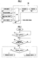
- FIG. 2 is a block diagram showing a passenger protection device in accordance with an embodiment of the present invention and peripheral devices thereof.
- the passenger protection device is provided with an ECU (electronic control unit) 108 configured to control the electric motor 104 in the retractor 103 used for driving the webbing 102.
- the ECU 108 receives the following signals in this embodiment a wipers ON signal obtained from the wiper switch 110, a headlights ON signal and a parking lights ON signal obtained from the headlight switch 111, a brake signal obtained from a brake pedal sensor 107, and a detection signal obtained from the buckle switch 112 (which detects if the tongue is inserted into the inner buckle 105).
- a vehicle speed signal is obtained from a vehicle speed detecting device installed on the vehicle.
- step S1 the ECU 108 detects if the buckle switch 112 is on or off in order to determine if the tongue is set in the inner buckle 105.
- the buckle switch is on when the tongue is set therein. If the buckle switch 112 is on, the ECU 108 proceeds to step S2, where it determines if emergency braking has been detected.
- the ECU 108 returns to step S2 if emergency braking is not detected, but the invention is not limited to such an arrangement; it is also acceptable for the ECU108 to return to step S1 and detect the on/off state of the buckle switch 112.
- step S3 the ECU 108 determines if the parking lights are on. If emergency braking is detected and the parking lights are determined to be on ("Yes" in step S3), the ECU 108 sets the brake operation threshold value (emergency braking threshold value) that serves as the condition for retracting the webbing 102 to a threshold value B. If the parking lights are not on (“No" in step S3), the ECU 108 sets the brake operation threshold value (emergency braking threshold value) that serves as the condition for retracting the webbing 102 to a threshold value A.
- the brake operation threshold value emergency braking threshold value
- Figure 7 is a characteristic diagram illustrating the relationship between the depression amount of the brake pedal 106, the depression speed of the brake pedal 106, and the thresbold value used for retracting webbing 102.
- the threshold value B is used, the webbing 102 is retracted at a smaller brake pedal depression amount than when the threshold value Ais used
- the webbing 102 is retracted early and the passenger restraining performance can be improved.
- the flowchart of Figure 4 shows the processing by which the brake operation threshold value for retracting the webbing 102 is revised in response to the wipers ON signal obtained from the wiper switch 110.
- the steps preceding step S13 are the same as steps S1 and S2 of Figure 3 and are omitted from the figure.
- the ECU 108 determines that the wipers are on in step S13, it sets the brake operation threshold value that serves as the condition for retracting the webbing 102 to a threshold value C. If the ECU 108 determines that the wipes are not on, it sets the brake operation threshold value that serves as the condition for retracting the webbing 102 to a threshold value A.
- the brake operation threshold value is revised from the threshold value A to the threshold value C as shown in Figure 7 and, as a result, the webbing 102 is retracted at a smaller depression amount of the brake pedal 106.
- the threshold value C the webbing 102 is retracted early and the passenger can be restrained at a more appropriate timing.
- the flowchart of Figure 5 shows the processing by which the brake operation threshold value for retracting the webbing 102 is revised in response to the headlights ON signal obtained from the headlight switch 111.
- the steps preceding step S23 are the same as steps S1 and S2 of Figure 3 and are omitted from the figure.
- the ECU 108 detects that the headlights are on in step S23, it sets the brake operation threshold value that serves as the condition for retracting the webbing 102 to a threshold value D. If the ECU 108 determines that the headlights are not on, it sets the brake operation threshold value that serves as the condition for retracting the webbing 102 to the threshold value A.
- the brake operation threshold value is revised from the threshold value A to the threshold value D as shown in Figure 7 and, as a result, the webbing 102 is retracted at a smaller depression amount of the brake pedal 106.
- the threshold value D the webbing 102 is retracted early and the passenger can be restrained at a more appropriate timing.
- the flowchart of Figure 6 shows the processing by which the brake operation threshold value for retracting the webbing 102 is revised in response to the wipers ON signal obtained from the wiper switch 110 and the headlights ON signal obtained from the headlight switch 111.
- the steps preceding step S33 are the same as steps S1 and S2 of Figure 3 and are omitted from the figure.
- the ECU 108 detects that the wipers are on in step S33 and the headlights are on in step S34, it sets the brake operation threshold value that serves as the condition for retracting the webbing 102 early to a threshold value E.
- the brake operation threshold value set to the threshold value E as shown in Figure 7 and, as a result, the webbing 102 is retracted at a smaller depression amount of the brake pedal 106.
- the threshold value E the webbing 102 is retracted early and the passenger can be restrained at a more appropriate timing.
- a passenger protection device 100 in accordance with the present embodiment can revise the brake operation threshold value used to retract the webbing 102 based on safety related information that includes, but not limited to, the on/off status of the parkings lights, the windshield wipers, and the headlights.
- the threshold value can be set to a value well-suited to the quality of the outside visibility and the webbing 102 can be retracted based on the threshold value.
- the passenger can be restrained at an even more appropriate timing.
- the threshold value is set to a lower value such that the webbing 102 is retracted at an even smaller depression amount of the brake pedal 106.
- the passsenger can be restrained at an even more appropriate timing.
- the brake operation threshold value is set to the threshold value A, which is the largest value.
- the threshold value A which is the largest value.
- the present invention is not limited to such a feature and it is also feasible for these threshold values to be the same.
- the flowchart of Figure 6 presents a case in which the brake operation threshold value is set to a threshold value E that is lower than the threshold values B, C, and D when it is detected that both the wipers and the headlights are on, it is also feasible to set the brake operation threshold value to a value lower than the threshold values B, C, and D when it is detected that both the wipers and the parking lights are on.
- the wipers ON signal is issued from a wiper switch 110 and the headlights ON and parking lights ON signals are issued from a headlight switch 111, it is also feasible to detect the actual operation of the wipers and use the resulting detection signal as the wipers ON signal and to detect the illumination of the headlights and parking lights and use the respective resulting detection signals as headlights ON and parking lights ON signals.
- a passenger protection device in accordance with the first embodiment takes the visibility of the vehicles surroundings into consideration and makes it possible to retract the seatbelt at an appropriate timing.
- FIG. 8 is diagrammatic view for explaining a second embodiment of a passenger protection device in accordance with the present invention. Descriptions of part that are the same as those of the first embodiment are omitted
- a brake pedal 106, a brake pedal sensor 107 configured to detect the movement of the brake pedal 106, an accelerator pedal 113, and an accelerator pedal sensor 109 configured to detect the movement of the accelerator pedal 109 are provided at the feet of the passenger P.
- the information detected by the brake pedal sensor 107 includes the timing at which the driver starts depressing the brake pedal, the amount by which the brake pedal is depressed, the speed at which the brake pedal is depressed, and other such information related to the movement of the brake pedal 106.
- the information detected by the accelerator pedal sensor 109 includes the amount by which the accelerator pedal is depressed, the timing at which the driver starts releasing the accelerator pedal the speed at which the accelerator pedal is released, and other such information related to the movement of the accelerator pedal 113.
- the passenger protection device 100 of the second embodiment is provided with an ECU 108 configured to control the electric motor 104 used for driving the webbing 102.
- the ECU 108 is receives the following signals in this embodiment a brake signal obtained from the brake pedal sensor 107, an accelerator signal obtained from the accelerator pedal sensor 109, and a detection signal obtained from the budde switch 112 (which detects if the tongue is inserted into the inner buckle 105). Also, a vehicle speed signal is obtained from a vehicle speed detecting device (not shown) installed on the vehicle.
- the ECU 108 determines that an emergency brake operation has occurred and operates the electric motor 104 so as to retract the webbing 102 and restrain the passenger P.
- the ECU 108 revises the motor operation threshold value in accordance with the timing at which the driver starts releasing the accelerator pedal 113 and the timing at which the driver starts depressing the brake pedal 106. More specifically, the shorter the pedal switch time, i.e., the shorter the difference between the timing at which the driver starts releasing the accelerator pedal 113 and the timing at which the driver starts depressing the brake pedal 106, the smaller the value to which the motor operation threshold value is revised. Based on the detection information from the accelerator pedal sensor 109, the faster the release speed of the accelerator pedal 113 is, the smaller the value to which the motor operation threshold value is revised will be.
- the motor operation threshold value is set as a linear function (first order polynomial) or nonlinear function (higher order polynomial) of the release speed of the accelerator pedal 113 or the pedal switch time, which is the amount of time from when the driver starts releasing the accelerator pedal 113 until the driver starts depressing the brake pedal 106.
- the pedal switch time i.e., the amount of time from when the driver starts releasing the accelerator pedal 113 until the driver starts depressing the brake pedal 106
- the motor operation threshold value is set to a lower value in order to increase the sensitivity with which emergency braking is detected, thereby enabling an emergency brake operation to be detected with a smaller the depression amount of the brake pedal 106 or a slower depression speed
- the electric motor 104 is operated at an earlier timing and the passenger P is restrained by the retraction of the webbing 102 at an earlier timing.
- step S41 of Figure 10 the ECU 108 determines if the detection signal from the buckle switch 112 is on off in order to detect if the seatbelt is fastened, i.e., if seatbelt is being worn with the tongue inserted into the inner buckle 105. If the seatbelt is not fastened , the ECU repeat step S41. If the seatbelt is fastened, the ECU 108 proceeds to step S42
- step S42 based on the detection information from the accelerator pedal sensor 109 and the brake pedal sensor 107, the ECU 108 determines if the accelerator pedal 113 was released and the action of depressing the brake pedal 106 was started in the immediate past If not, the ECU 108 returns to step S41. If so, the ECU 108 reads in the pedal switch time, i.e., the difference between the timing at which the driver started releasing the accelerator pedal 113 and the timing at which the driver started depressing the brake pedal 106, and proceeds to step S43.
- step S43 the ECU 108 determines if the acquired pedal switch time is less than a prescribed amount of time. If the pedal switch time is equal to or larger than the prescribed amount of time, the ECU 108 determines that an emergency brake operation has not been detected and returns to step S41. If the pedal switdi time is less than the prescribed amount of time, the ECU 108 determines that an emergency brake operation has been detected and proceeds to step S44.
- step S44 the ECU 108 revises the motor operation threshold value to a smaller value in such a manner that the shorter the pedal switch time (i.e., the amount of time from when the driver starts releasing the accelerator pedal 113 until the driver starts depressing the brake pedal 106) is, the earlier the timing at which the electric motor 104 is operated becomes.
- the flowchart of Figure 11 describes a second revision processing for revising the motor operation threshold value in a passenger protection device 100 in accordance the second embodiment.
- the ECU 108 determines if the buckle switch 112 is on or off (based on the detection signal thereof) in order to detect if the seatbelt is fastened, i.e., if the seatbelt is being worn with the tongue inserted into the inner buckle 105. If the seatbelt is not fastened, the ECU 108 repeats step S51. If the seatbelt is fastened, the ECU 108 proceeds to step S52.
- step S52 based on the detection information from the accelerator pedal sensor 109, the ECU 108 determines if the accelerator pedal 113 was released in the immediate past. If not, the ECU 108 returns to step S51. If so, the ECU 108 reads in the release speed and release amount and proceeds to step S53.
- step S53 the ECU 108 determines if the acquired release speed and release amount of the accelerator pedal 113 are equal to or larger than prescribed values. If the release speed and release amount of the accelerator pedal 113 are less than prescribed values, the ECU 108 determines that an emergency brake operation has not been detected and returns to step S51. If the release speed and release amount of the accelerator pedal 113 are equal to or larger than prescribed values, the ECU 108 determines that an emergency brake operation has been detected and proceeds to step S54.
- step S54 the ECU 108 revises the motor operation threshold value to a smaller value in such a manner that the faster return speed of the accelerator pedal 113 is, the earlier the timing at which the electric motor 104 is operated becomes.
- Figure 12 illustrates the first setting method in which the motor operation threshold value is set as a linear function of the pedal switch time, ie., the amount of time from when the driver starts releasing the accelerator pedal 113 until the driver starts the brake pedal 106, or the release speed the accelerator or pedal 113.
- the motor operation threshold values are shown on a plot in which the vertical axis indicates the depression speed of the brake pedal 106 and the horizontal axis indicates the depression amount of the brake pedal 106.
- the ECR 108 determines that an emergency brake operation has occurred and operates the electric motor 104 so that the webbing 102 is retracted and the passenger P is restrain
- the timing at which the webbing 102 of the seatbelt is retracted is advanced by setting the motor operation threshold value to successively lower values A, B, C, and D (in that order) so that the electric motor 104 is operated when the brake pedal 106 is depressed at comparatively slower depression speeds or the brake pedal 106 is depressed to comparatively smaller depression amounts.
- the motor operation threshold values are shown on a plot in which the vertical axis indicates the pedal switch time, i.e., the amount of time from when the driver starts releasing the accelerator pedal 113 until the driver starts depressing the brake pedal 106, or the release speed the accelerator pedal 113 and the horizontal axis indicates the depression amount of the brake pedal 106.
- the motor operation threshold value is set as a linear function of the vertical axis variable (i.e., the pedal switch time or accelerator pedal release speed).
- the motor operation threshold value is set in a linear fashion with respect to the pedal switch time or the accelerator pedal release speed in such a manner that the shorter the pedal switch time or the faster the accelerator pedal 113 release speed is, the lower the motor operation threshold value is set.
- the revision processing executed by the ECU 108 is digital processing and the straight line shown sloping down and to the right in the lower portion of Figure 12 would be more accurately depicted as step-like graph.
- Figure 13 illustrates the second setting method in which the motor operation threshold value is set as a higher order function of the pedal switch time, i.e., the amount of time from when the driver starts releasing the accelerator pedal 113 until the driver starts depressing the brake pedal 106, or the release speed the accelerator pedal 113.
- the upper portion of Figure 13 is the same as the upper portion of Figure 12
- the motor operation threshold values are shown on a plot in which the vertical axis indicates the pedal switch time, i.e., the amount of time from when the driver starts releasing the accelerator pedal 113 until the driver starts depressing the brake pedal 106, or the release speed the accelerator pedal 113 and the horizontal axis indicates the depression amount of the brake pedal 106.
- the motor operation threshold value is set as a higher order (curved) function of the vertical axis variable (i.e., the pedal switch time or accelerator pedal release speed).
- the motor operation threshold value is set in a curved fashion with respect to the pedal switch time or the accelerator pedal release speed in such a manner that the motor operation threshold value becomes gradually smaller when the pedal switch time or accelerator release speed is comparatively slow and becomes smaller more rapidly when the pedal switch time or accelerator release speed is comparatively fast
- the revision processing is digital processing executed by the ECU 108 and the straight line shown sloping-down and to the right in the lower portion of Figure 12 would be more accurately depicted as step-like graph.
- the revision processing executed by the ECU 108 is digital processing and the curved line shown sloping down and to the right in the lower portion of Figure 13 would be more accurately depicted as step-like graph.
- a passenger protection device in accordance with the second embodiment is a passenger protection device configured to operate an electric motor 104 so as to retract the webbing 102 of a seatbelt and restrain a passenger when a detection value based on safety related information exceeds a motor operation threshold value, said safety related information including such vehicle driving operations as operation of the accelerator pedal and brake pedal.
- an ECU (controller) 108 Based on detection information from an accelerator pedal sensor 109 and a brake pedal sensor 107, an ECU (controller) 108revises the motor operation threshold value in accordance with the timing at which the driver starts releasing the accelerator pedal 113 and the timing at which the driver starts depressing the brake pedal 106.
- emergency braking can be detected earlier and more accurately in accordance with the driving conditions and the timing at which the webbing 102 of the seatbelt is retracted can be advanced by revising the motor operation threshold value to a lower value. As a result, the forward movement experienced by the passenger in a collision can be reduced
- the ECU 108 uses detection information from the accelerator pedal sensor 109 and the brake pedal sensor 107 to revise the motor operation threshold value in such a manner that the shorter the pedal switch time, i.e., the shorter the difference between the timing at which the driver starts releasing the accelerator pedal 113 and the timing at which the driver starts depressing the brake pedal 106, the smaller the value to which the motor operation threshold value is revised; or the ECU 108 uses detection information from the accelerator pedal sensor 109 to revise the motor operation threshold value in such a manner that the faster the speed at which the accelerator pedal 113 is released, the smaller the value to which the motor operation threshold value is revised.
- this embodiment increases the sensitivity with which emergency braking is detected and advances the timing at which the webbing is retracted only when it is highly probable that an emergency brake operation will occur. As a result, a high degree of passenger protection is achieved while also reducing the annoyance associated with emergency braking so that degradation of the passenger's comfort is avoided.
- the motor operation threshold value is set as a linear function or higher order function of the release speed of the accelerator pedal 113 or the pedal switch time, which is the amount of time from when the driver starts releasing the accelerator pedal 113 until the driver starts depressing the brake pedal 106.
- the function used to revise the motor operation threshold value can be changed in accordance with the road conditions and driving conditions and emergency braking can be detected earlier and more accurately in accordance with the driving conditions.
- the ECU 108 uses the depression amount and depression speed of the brake pedal 106 as the aforementioned detection values based on vehicle driving operations for determining if the passenger should be restrained by operating the motor 104 and retracting the webbing 102
- the invention is not limited to such an approach. It is also acceptable to use detection information from the accelerator pedal sensor 109, information regarding the steering angle of the steering wheel 10, the vehicle speed, a combination of these, or a combination of one or more of these including the detection information from the brake pedal sensor 107.
- detection information from the accelerator pedal sensor and the brake pedal sensor are used to revise the motor operation threshold value in accordance with the timing at which the driver starts releasing the accelerator pedal 113 and the timing at which the driver starts depressing the brake pedal 106.
- the second embodiment can detect emergency braking earlier and more accurately in accordance with the driving conditions and the timing at which the webbing of the seatbelt is retracted can be advanced by revising the motor operation threshold value to a lower value. As a result, the forward movement experienced by the passenger in a collision can be reduced.
- the second embodiment increases the sensitivity with which emergency braking is detected and advances the timing at which the webbing is retracted only when it is highly probable that an emergency brake operation will occur. As a result, a high degree of passenger protection is achieved while also reducing the annoyance associated with emergency braking so that degradation of the passenger's comfort is avoided
Abstract
Description
- The present invention relates to a passenger protection device configured to retract the webbing of a seatbelt using an electric motor. More particularly, the present invention relates to a technology for controlling the retraction of the webbing in accordance with the situation.
- Japanese Laid-Open Patent Publication No.
2001-253317 - Additionally, Japanese Laid-Open Patent Publication No.
2000-190815 - The technologies disclosed in Japanese Laid-Open Patent Publication No.
2001-253317 2000-190815 - Meanwhile, if one attempts to increase the restraining performance by merely speeding up the timing at which an emergency situation is determined to exist, the degree of passenger protection may improve but the device will be lacking from the perspective of driver comfort because it will become an annoyance.
- The present invention was conceived to address these issues and its object is to provide a passenger protection device that takes the driving conditions into consideration and ensures a high restraining performance without debasing the comfort of the passenger.
- An aspect of the present invention provides a passenger protection device that includes, a brake pedal sensor configured to detect the amount by which a brake pedal of a vehicle is operated, a webbing, one end of the webbing fixed to the vehicle, configured to restrain a passenger seated on a seat of the vehicle, a retractor connected to the other end of the webbing, the retractor configured to retract the webbing and inhibit of the webbing extraction, and an ECU electrically coupled to the brake pedal sensor, the ECU configured to detect that the brake pedal operation amount detected by the pedal sensor exceeds a first threshold value, the ECU configured to revise the threshold value based on safety related information of the vehicle to control the inhibition of the webbing extraction of the retractor.
-
-
Figure 1 is a diagrammatic view for explaining a first embodiment of a passenger protection device in accordance with the present invention. -
Figure 2 is a block diagram showing a passenger protection device in accordance with the first embodiment of the present invention and peripheral devices thereof. -
Figure 3 is a flowchart showing the processing by which the brake operation threshold value for retracting thewebbing 102 is revised in response to the parking lights ON signal obtained from theheadlight switch 111 and the detection signal obtained from thebuckle switch 112 -
Figure 4 is a flowchart showing the processing by which the brake operation threshold value for retracting thewebbing 102 is revised in response to the wipers ON signal obtained from thewiper switch 110. -
Figure 5 is a flowchart showing the processing by which the brake operation threshold value for retracting thewebbing 102 is revised in response to the headlights ON signal obtained from theheadlight switch 111. -
Figure 6 is a flowchart showing the processing by which the brake operation threshold value for retracting thewebbing 102 is revised in response to the wipes ON signal obtained from thewiper switch 110 and the headlights ON signal obtained from theheadlight switch 111. -
Figure 7 is a characteristic diagram illustrating the relationship between the depression amount of thebrake pedal 106, the depression speed of thebrake pedal 106, and the threshold value used for retractingwebbing 102. -
Figure 8 is diagrammatic view for explaining a second embodiment of a passenger protection device in accordance with the present invention. -
Figure 9 is a block diagram showing a passenger protection device in accordance with the second embodiment of the present invention and peripheral devices thereof. -
Figure 10 is a flowchart showing a first revision processing for revising the motor operation threshold value in apassenger protection device 100 in accordance the second embodiment. -
Figure 11 is a flowchart showing a second revision processing for revising the motor operation threshold value in apassenger protection device 100 in accordance the second embodiment. -
Figure 12 illustrates the first setting method in which the motor operation threshold value is set as a linear function of the pedal switch time, i.e., the amount of time from when the driver starts releasing theaccelerator pedal 113 until the driver starts depressing thebrake pedal 106, or the release speed theaccelerator pedal 113. -
Figure 13 illustrates the second setting method in which the motor operation threshold value is set as a higher order function of the pedal switch time, i.e., the amount of time from when the driver starts releasing theaccelerator pedal 113 until the driver starts depressing thebrake pedal 106, or the release speed theaccelerator pedal 113. - Various embodiments of the present invention will be described with reference to the accompanying drawings. It is to be noted that same or similar reference numerals are applied to the same or similar parts and elements throughout the drawings, and the description of the same or similar parts and elements win be omitted or simplified
-
Figure 1 is a diagrammatic view for explaining a first embodiment of a passenger protection device in accordance with the present invention. Thepassenger protection device 100 is provided with awebbing 102 that serves to restrain a passenger P sitting in a seat S, and aretractor 103 configured to store thewebbing 102 using anelectric motor 104 configured to provided power to wind up one end of thewebbing 102. The other end of the seatbelt is fastened to the vehicle body through an anchor arranged on the door side of the seat S. - The
retractor 103 is configured to retract thewebbing 102 and inhibits of extraction of thewebbing 102 when the brake pedal operation amount detected by thepedal sensor 107 exceeds a threshold value prevents thewebbing 102 from being extract (drawn out) when the vehicle experiences a prescribed deceleration. - A tongue is attached in a freely movable manner to an intermediate part of the
webbing 102 and is configured to engage in a detachable manner with aninner budde 105 that is fastened to the vehicle body at a transversely-middle portion of the seat S. Thewebbing 102 is supported in a freely movable manner at a position between theinner budde 105 and theretractor 103 by ashoulder anchor 101 provided on an upper portion of the center pillar. - A
brake pedal 106 and abrake pedal sensor 107 configured to detect operation of thebrake pedal 106 such as the depression amount and depression speed of thebrake pedal 106 are provided at the feet of the passenger P. Also, aheadlight switch 111 and awindshield wiper switch 110 are provided on the steering column. -
Figure 2 is a block diagram showing a passenger protection device in accordance with an embodiment of the present invention and peripheral devices thereof. As shown in the figure, the passenger protection device is provided with an ECU (electronic control unit) 108 configured to control theelectric motor 104 in theretractor 103 used for driving thewebbing 102. TheECU 108 receives the following signals in this embodiment a wipers ON signal obtained from thewiper switch 110, a headlights ON signal and a parking lights ON signal obtained from theheadlight switch 111, a brake signal obtained from abrake pedal sensor 107, and a detection signal obtained from the buckle switch 112 (which detects if the tongue is inserted into the inner buckle 105). Also, a vehicle speed signal is obtained from a vehicle speed detecting device installed on the vehicle. - The operation of a
passenger protection device 100 in accordance with the fast embodiment will now be explained with reference to the flowcharts ofFigures 3 to 6 . The flowchart ofFigure 3 shows the processing by which the brake operation threshold value for retracting thewebbing 102 is revised in response to the parking lights ON signal obtained from theheadlight switch 111 and the detection signal obtained from thebuckle switch 112 First, in step S1, theECU 108 detects if thebuckle switch 112 is on or off in order to determine if the tongue is set in theinner buckle 105. The buckle switch is on when the tongue is set therein. If thebuckle switch 112 is on, the ECU 108 proceeds to step S2, where it determines if emergency braking has been detected. In this embodiment, theECU 108 returns to step S2 if emergency braking is not detected, but the invention is not limited to such an arrangement; it is also acceptable for the ECU108 to return to step S1 and detect the on/off state of thebuckle switch 112. In step S3, the ECU 108 determines if the parking lights are on. If emergency braking is detected and the parking lights are determined to be on ("Yes" in step S3), theECU 108 sets the brake operation threshold value (emergency braking threshold value) that serves as the condition for retracting thewebbing 102 to a threshold value B. If the parking lights are not on ("No" in step S3), theECU 108 sets the brake operation threshold value (emergency braking threshold value) that serves as the condition for retracting thewebbing 102 to a threshold value A. -
Figure 7 is a characteristic diagram illustrating the relationship between the depression amount of thebrake pedal 106, the depression speed of thebrake pedal 106, and the thresbold value used for retractingwebbing 102. When the threshold value B is used, thewebbing 102 is retracted at a smaller brake pedal depression amount than when the threshold value Ais used - In ambient conditions under which the parking lights are turned on, i.e., when the outside environment of the vehicle is dimly lighted, there is the possibility that the brakes will be operated late because the surroundings are difficult to discern. By using the threshold value B, the
webbing 102 is retracted early and the passenger restraining performance can be improved. - The flowchart of
Figure 4 shows the processing by which the brake operation threshold value for retracting thewebbing 102 is revised in response to the wipers ON signal obtained from thewiper switch 110. The steps preceding step S13 are the same as steps S1 and S2 ofFigure 3 and are omitted from the figure. - In this embodiment, if the
ECU 108 determines that the wipers are on in step S13, it sets the brake operation threshold value that serves as the condition for retracting thewebbing 102 to a threshold value C. If theECU 108 determines that the wipes are not on, it sets the brake operation threshold value that serves as the condition for retracting thewebbing 102 to a threshold value A. - Thus, in ambient conditions under which the windshield wipers are turned on, i.e., when it is raining or snowing, the brake operation threshold value is revised from the threshold value A to the threshold value C as shown in
Figure 7 and, as a result, thewebbing 102 is retracted at a smaller depression amount of thebrake pedal 106. When it is raining or snowing, there is the possibility that the brakes will be operated late because of poor visibility. By using the threshold value C, thewebbing 102 is retracted early and the passenger can be restrained at a more appropriate timing. - The flowchart of
Figure 5 shows the processing by which the brake operation threshold value for retracting thewebbing 102 is revised in response to the headlights ON signal obtained from theheadlight switch 111. The steps preceding step S23 are the same as steps S1 and S2 ofFigure 3 and are omitted from the figure. - In this example, if the
ECU 108 detects that the headlights are on in step S23, it sets the brake operation threshold value that serves as the condition for retracting thewebbing 102 to a threshold value D. If theECU 108 determines that the headlights are not on, it sets the brake operation threshold value that serves as the condition for retracting thewebbing 102 to the threshold value A. - Thus, in ambient conditions under which the headlights are turned on, i.e., when the vehicle is traveling at night or through a tunnel, the brake operation threshold value is revised from the threshold value A to the threshold value D as shown in
Figure 7 and, as a result, thewebbing 102 is retracted at a smaller depression amount of thebrake pedal 106. When it is dark, there is the possibility that the brakes will be operated late. By using the threshold value D, thewebbing 102 is retracted early and the passenger can be restrained at a more appropriate timing. - The flowchart of
Figure 6 shows the processing by which the brake operation threshold value for retracting thewebbing 102 is revised in response to the wipers ON signal obtained from thewiper switch 110 and the headlights ON signal obtained from theheadlight switch 111. The steps preceding step S33 are the same as steps S1 and S2 ofFigure 3 and are omitted from the figure. - In this example, if the
ECU 108 detects that the wipers are on in step S33 and the headlights are on in step S34, it sets the brake operation threshold value that serves as the condition for retracting thewebbing 102 early to a threshold value E. - Thus, in ambient conditions under which both the wipers and the headlights are turned on, e.g., when the vehicle is traveling at night in rainy weather, the brake operation threshold value set to the threshold value E as shown in
Figure 7 and, as a result, thewebbing 102 is retracted at a smaller depression amount of thebrake pedal 106. When the surroundings are dark and visibility is poor due to rain, there is the possibility that the brakes will be operated late. By using the threshold value E, thewebbing 102 is retracted early and the passenger can be restrained at a more appropriate timing. In this way, apassenger protection device 100 in accordance with the present embodiment can revise the brake operation threshold value used to retract thewebbing 102 based on safety related information that includes, but not limited to, the on/off status of the parkings lights, the windshield wipers, and the headlights. The threshold value can be set to a value well-suited to the quality of the outside visibility and thewebbing 102 can be retracted based on the threshold value. Thus, the passenger can be restrained at an even more appropriate timing. - When the threshold value is revised based on two or conditions from among the on/off status of the parking lights, the on/off status of the windshield wipers, and the on/off status of the headlights, the threshold value is set to a lower value such that the
webbing 102 is retracted at an even smaller depression amount of thebrake pedal 106. As a result, the passsenger can be restrained at an even more appropriate timing. - Meanwhile, when the parking lights, the windshield wipers, and the headlights are all off, the brake operation threshold value is set to the threshold value A, which is the largest value. As a result, unnecessary retracting of the
webbing 102 is avoided and the passenger protection device does not become an annoyance to the passenger. In other words, since the emergency braking threshold value is higher when the visibility is good than when the visibility is poor, the probability of the webbing being retracted for no reason is decreased and the degree of annoyance to the passenger can be reduced - Although a passenger protection device in accordance with the present invention has been described heretofore based on an embodiment depicted in the drawings, the present invention is not limited to that embodiment. The constituent features of the various parts can be changed as desired so long as the parts have the same functions.
- For example, although in the previously described embodiment all of the threshold values B, C, and D are different, the present invention is not limited to such a feature and it is also feasible for these threshold values to be the same. Furthermore, although the flowchart of
Figure 6 presents a case in which the brake operation threshold value is set to a threshold value E that is lower than the threshold values B, C, and D when it is detected that both the wipers and the headlights are on, it is also feasible to set the brake operation threshold value to a value lower than the threshold values B, C, and D when it is detected that both the wipers and the parking lights are on. - Furthermore, although in the previously described embodiment the wipers ON signal is issued from a
wiper switch 110 and the headlights ON and parking lights ON signals are issued from aheadlight switch 111, it is also feasible to detect the actual operation of the wipers and use the resulting detection signal as the wipers ON signal and to detect the illumination of the headlights and parking lights and use the respective resulting detection signals as headlights ON and parking lights ON signals. - When the vehicle is traveling in rainy weather, in snowy weather at night, in a tunnel, or in some other condition under which it is more difficult to discern the surroundings of the vehicle than when the vehicle is traveling in clear weather or in the daylight hours, them is the possibility that the driver's judgment of an emergency situation will be late and thus the timing at which the driver depresses the brake pedal will be late. Thus, there is the possibility that the timing at which the electric motor retracts the seatbelt will be late.
- A passenger protection device in accordance with the first embodiment takes the visibility of the vehicles surroundings into consideration and makes it possible to retract the seatbelt at an appropriate timing.
-
Figure 8 is diagrammatic view for explaining a second embodiment of a passenger protection device in accordance with the present invention. Descriptions of part that are the same as those of the first embodiment are omitted Abrake pedal 106, abrake pedal sensor 107 configured to detect the movement of thebrake pedal 106, anaccelerator pedal 113, and anaccelerator pedal sensor 109 configured to detect the movement of theaccelerator pedal 109 are provided at the feet of the passenger P. The information detected by thebrake pedal sensor 107 includes the timing at which the driver starts depressing the brake pedal, the amount by which the brake pedal is depressed, the speed at which the brake pedal is depressed, and other such information related to the movement of thebrake pedal 106. Meanwhile, the information detected by theaccelerator pedal sensor 109 includes the amount by which the accelerator pedal is depressed, the timing at which the driver starts releasing the accelerator pedal the speed at which the accelerator pedal is released, and other such information related to the movement of theaccelerator pedal 113. - As shown in
Figure 9 , thepassenger protection device 100 of the second embodiment is provided with anECU 108 configured to control theelectric motor 104 used for driving thewebbing 102. TheECU 108 is receives the following signals in this embodiment a brake signal obtained from thebrake pedal sensor 107, an accelerator signal obtained from theaccelerator pedal sensor 109, and a detection signal obtained from the budde switch 112 (which detects if the tongue is inserted into the inner buckle 105). Also, a vehicle speed signal is obtained from a vehicle speed detecting device (not shown) installed on the vehicle. - In this embodiment, when a detection value based on a vehicle driving operation (in this embodiment, the depression amount or depression speed of the brake pedal 106) exceeds a prescribed motor operation threshold value, the
ECU 108 determines that an emergency brake operation has occurred and operates theelectric motor 104 so as to retract thewebbing 102 and restrain the passenger P. - Based on detection information from the
accelerator pedal sensor 109 and thebrake pedal sensor 107, theECU 108 revises the motor operation threshold value in accordance with the timing at which the driver starts releasing theaccelerator pedal 113 and the timing at which the driver starts depressing thebrake pedal 106. More specifically, the shorter the pedal switch time, i.e., the shorter the difference between the timing at which the driver starts releasing theaccelerator pedal 113 and the timing at which the driver starts depressing thebrake pedal 106, the smaller the value to which the motor operation threshold value is revised. Based on the detection information from theaccelerator pedal sensor 109, the faster the release speed of theaccelerator pedal 113 is, the smaller the value to which the motor operation threshold value is revised will be. The motor operation threshold value is set as a linear function (first order polynomial) or nonlinear function (higher order polynomial) of the release speed of theaccelerator pedal 113 or the pedal switch time, which is the amount of time from when the driver starts releasing theaccelerator pedal 113 until the driver starts depressing thebrake pedal 106. - If the pedal switch time, i.e., the amount of time from when the driver starts releasing the
accelerator pedal 113 until the driver starts depressing thebrake pedal 106, is short or if the speed at which theaccelerator pedal 113 is released is fast, it is highly probable that the depression operation of the brake pedal 8 about to occur will be an emergency brake operation. In such a case, the motor operation threshold value is set to a lower value in order to increase the sensitivity with which emergency braking is detected, thereby enabling an emergency brake operation to be detected with a smaller the depression amount of thebrake pedal 106 or a slower depression speed As a result, theelectric motor 104 is operated at an earlier timing and the passenger P is restrained by the retraction of thewebbing 102 at an earlier timing. - The operation of a
passenger protection device 100 in accordance with the second embodiment will now be explained with reference to the flowcharts ofFigures 10 and 11 and also to diagrams shown inFigures 12 and 13 . The flowchart ofFigure 10 describes a first revision processing for revising the motor operation threshold value in apassenger protection device 100 in accordance the second embodiment In step S41 ofFigure 10 , theECU 108 determines if the detection signal from thebuckle switch 112 is on off in order to detect if the seatbelt is fastened, i.e., if seatbelt is being worn with the tongue inserted into theinner buckle 105. If the seatbelt is not fastened , the ECU repeat step S41. If the seatbelt is fastened, theECU 108 proceeds to step S42 - In step S42, based on the detection information from the
accelerator pedal sensor 109 and thebrake pedal sensor 107, theECU 108 determines if theaccelerator pedal 113 was released and the action of depressing thebrake pedal 106 was started in the immediate past If not, theECU 108 returns to step S41. If so, theECU 108 reads in the pedal switch time, i.e., the difference between the timing at which the driver started releasing theaccelerator pedal 113 and the timing at which the driver started depressing thebrake pedal 106, and proceeds to step S43. - In step S43, the
ECU 108 determines if the acquired pedal switch time is less than a prescribed amount of time. If the pedal switch time is equal to or larger than the prescribed amount of time, theECU 108 determines that an emergency brake operation has not been detected and returns to step S41. If the pedal switdi time is less than the prescribed amount of time, theECU 108 determines that an emergency brake operation has been detected and proceeds to step S44. - In step S44, the
ECU 108 revises the motor operation threshold value to a smaller value in such a manner that the shorter the pedal switch time (i.e., the amount of time from when the driver starts releasing theaccelerator pedal 113 until the driver starts depressing the brake pedal 106) is, the earlier the timing at which theelectric motor 104 is operated becomes. - The flowchart of
Figure 11 describes a second revision processing for revising the motor operation threshold value in apassenger protection device 100 in accordance the second embodiment. In step S51 ofFigure 11 , theECU 108 determines if thebuckle switch 112 is on or off (based on the detection signal thereof) in order to detect if the seatbelt is fastened, i.e., if the seatbelt is being worn with the tongue inserted into theinner buckle 105. If the seatbelt is not fastened, theECU 108 repeats step S51. If the seatbelt is fastened, theECU 108 proceeds to step S52. - In step S52, based on the detection information from the
accelerator pedal sensor 109, theECU 108 determines if theaccelerator pedal 113 was released in the immediate past. If not, theECU 108 returns to step S51. If so, theECU 108 reads in the release speed and release amount and proceeds to step S53. - In step S53, the
ECU 108 determines if the acquired release speed and release amount of theaccelerator pedal 113 are equal to or larger than prescribed values. If the release speed and release amount of theaccelerator pedal 113 are less than prescribed values, theECU 108 determines that an emergency brake operation has not been detected and returns to step S51. If the release speed and release amount of theaccelerator pedal 113 are equal to or larger than prescribed values, theECU 108 determines that an emergency brake operation has been detected and proceeds to step S54. - In step S54, the
ECU 108 revises the motor operation threshold value to a smaller value in such a manner that the faster return speed of theaccelerator pedal 113 is, the earlier the timing at which theelectric motor 104 is operated becomes. - The method by which the motor operation threshold value is set in step S44 of
Figure 10 and step S54 inFigure 11 will now be described in more detail with reference toFigures 12 and 13. Figure 12 illustrates the first setting method in which the motor operation threshold value is set as a linear function of the pedal switch time, ie., the amount of time from when the driver starts releasing theaccelerator pedal 113 until the driver starts thebrake pedal 106, or the release speed the accelerator orpedal 113. - In the upper portion of
Figure 12 , the motor operation threshold values are shown on a plot in which the vertical axis indicates the depression speed of thebrake pedal 106 and the horizontal axis indicates the depression amount of thebrake pedal 106. When the depression speed of thebrake pedal 106 is so fast as to exceed the motor operation threshold values A, B, C, and D or when the depression amount of thebrake pedal 106 is so large as to exceed the motor operation threshold values A, B, C, and D, theECR 108 determines that an emergency brake operation has occurred and operates theelectric motor 104 so that thewebbing 102 is retracted and the passenger P is restrain In short, the timing at which thewebbing 102 of the seatbelt is retracted is advanced by setting the motor operation threshold value to successively lower values A, B, C, and D (in that order) so that theelectric motor 104 is operated when thebrake pedal 106 is depressed at comparatively slower depression speeds or thebrake pedal 106 is depressed to comparatively smaller depression amounts. - In the lower portion of
Figure 12 , the motor operation threshold values are shown on a plot in which the vertical axis indicates the pedal switch time, i.e., the amount of time from when the driver starts releasing theaccelerator pedal 113 until the driver starts depressing thebrake pedal 106, or the release speed theaccelerator pedal 113 and the horizontal axis indicates the depression amount of thebrake pedal 106. Here, the motor operation threshold value is set as a linear function of the vertical axis variable (i.e., the pedal switch time or accelerator pedal release speed). In other words, the motor operation threshold value is set in a linear fashion with respect to the pedal switch time or the accelerator pedal release speed in such a manner that the shorter the pedal switch time or the faster theaccelerator pedal 113 release speed is, the lower the motor operation threshold value is set. The revision processing executed by theECU 108 is digital processing and the straight line shown sloping down and to the right in the lower portion ofFigure 12 would be more accurately depicted as step-like graph. However, it is possible to approach a continuous straight line by revising the motor operation threshold value in finer increments by preparing a larger number of present threshold values (A, B, C, D, E. F, etc.). -
Figure 13 illustrates the second setting method in which the motor operation threshold value is set as a higher order function of the pedal switch time, i.e., the amount of time from when the driver starts releasing theaccelerator pedal 113 until the driver starts depressing thebrake pedal 106, or the release speed theaccelerator pedal 113. - The upper portion of
Figure 13 is the same as the upper portion ofFigure 12 In the lower portion ofFigure 13 , the motor operation threshold values are shown on a plot in which the vertical axis indicates the pedal switch time, i.e., the amount of time from when the driver starts releasing theaccelerator pedal 113 until the driver starts depressing thebrake pedal 106, or the release speed theaccelerator pedal 113 and the horizontal axis indicates the depression amount of thebrake pedal 106. Here, the motor operation threshold value is set as a higher order (curved) function of the vertical axis variable (i.e., the pedal switch time or accelerator pedal release speed). In other words, the motor operation threshold value is set in a curved fashion with respect to the pedal switch time or the accelerator pedal release speed in such a manner that the motor operation threshold value becomes gradually smaller when the pedal switch time or accelerator release speed is comparatively slow and becomes smaller more rapidly when the pedal switch time or accelerator release speed is comparatively fast The revision processing is digital processing executed by theECU 108 and the straight line shown sloping-down and to the right in the lower portion ofFigure 12 would be more accurately depicted as step-like graph. However, it is possible to approach a continuous straight line by revising the motor operation threshold value A, B, C, and D in finer increments. The revision processing executed by theECU 108 is digital processing and the curved line shown sloping down and to the right in the lower portion ofFigure 13 would be more accurately depicted as step-like graph. However, it is possible to approach a continuous curve by revising the motor operation threshold value in finer increments by preparing a larger number of present threshold values (A, B, C, D, E, F, etc.). - Although
Figure 12 and Figure 13 illustrate cases in which the motor operation threshold value is revised in accordance with the pedal switch time or the accelerator release speed and no explanation is given regarding taking the release amount of theaccelerator pedal 113 into consideration, it is certainly possible to revise the motor operation threshold value - As explained previously, a passenger protection device in accordance with the second embodiment is a passenger protection device configured to operate an
electric motor 104 so as to retract thewebbing 102 of a seatbelt and restrain a passenger when a detection value based on safety related information exceeds a motor operation threshold value, said safety related information including such vehicle driving operations as operation of the accelerator pedal and brake pedal. Based on detection information from anaccelerator pedal sensor 109 and abrake pedal sensor 107, an ECU (controller) 108revises the motor operation threshold value in accordance with the timing at which the driver starts releasing theaccelerator pedal 113 and the timing at which the driver starts depressing thebrake pedal 106. By combining information from theaccelerator pedal 113 and information from thebrake pedal 106, emergency braking can be detected earlier and more accurately in accordance with the driving conditions and the timing at which thewebbing 102 of the seatbelt is retracted can be advanced by revising the motor operation threshold value to a lower value. As a result, the forward movement experienced by the passenger in a collision can be reduced - In a passenger protection device in accordance with the second embodiment, the
ECU 108 uses detection information from theaccelerator pedal sensor 109 and thebrake pedal sensor 107 to revise the motor operation threshold value in such a manner that the shorter the pedal switch time, i.e., the shorter the difference between the timing at which the driver starts releasing theaccelerator pedal 113 and the timing at which the driver starts depressing thebrake pedal 106, the smaller the value to which the motor operation threshold value is revised; or theECU 108 uses detection information from theaccelerator pedal sensor 109 to revise the motor operation threshold value in such a manner that the faster the speed at which theaccelerator pedal 113 is released, the smaller the value to which the motor operation threshold value is revised. Thus, unlike technologies that attempt to increase the passenger restraining performance by merely speeding up the timing at which an emergency situation is determined to exist, this embodiment increases the sensitivity with which emergency braking is detected and advances the timing at which the webbing is retracted only when it is highly probable that an emergency brake operation will occur. As a result, a high degree of passenger protection is achieved while also reducing the annoyance associated with emergency braking so that degradation of the passenger's comfort is avoided. - Furthermore, in a passenger protection device in accordance with the second embodiment, the motor operation threshold value is set as a linear function or higher order function of the release speed of the
accelerator pedal 113 or the pedal switch time, which is the amount of time from when the driver starts releasing theaccelerator pedal 113 until the driver starts depressing thebrake pedal 106. Thus, the function used to revise the motor operation threshold value can be changed in accordance with the road conditions and driving conditions and emergency braking can be detected earlier and more accurately in accordance with the driving conditions. - Although in the second embodiment the
ECU 108 uses the depression amount and depression speed of thebrake pedal 106 as the aforementioned detection values based on vehicle driving operations for determining if the passenger should be restrained by operating themotor 104 and retracting thewebbing 102, the invention is not limited to such an approach. It is also acceptable to use detection information from theaccelerator pedal sensor 109, information regarding the steering angle of the steering wheel 10, the vehicle speed, a combination of these, or a combination of one or more of these including the detection information from thebrake pedal sensor 107. - In a passenger protection device in accordance with the second embodiment, detection information from the accelerator pedal sensor and the brake pedal sensor are used to revise the motor operation threshold value in accordance with the timing at which the driver starts releasing the
accelerator pedal 113 and the timing at which the driver starts depressing thebrake pedal 106. Thus, by using a combination of information from the accelerator pedal and information from the brake pedal, the second embodiment can detect emergency braking earlier and more accurately in accordance with the driving conditions and the timing at which the webbing of the seatbelt is retracted can be advanced by revising the motor operation threshold value to a lower value. As a result, the forward movement experienced by the passenger in a collision can be reduced. Additionally, unlike technologies that attempt to increase the passenger restraining performance by merely speeding up the timing at which an emergency situation is determined to exist, the second embodiment increases the sensitivity with which emergency braking is detected and advances the timing at which the webbing is retracted only when it is highly probable that an emergency brake operation will occur. As a result, a high degree of passenger protection is achieved while also reducing the annoyance associated with emergency braking so that degradation of the passenger's comfort is avoided - The entire contents of Japanese patent applications
P2003-369253 filed October 29th, 2003 P2003-405941 filed December 4th, 2003 - The invention may be embodied in other specific forms without departing from the spirit or essential characteristics thereof. The present embodiment is therefore to be cons:idered in all respects as illustrative and not restrictive, the scope of the invention being indicated by the appended claims rather than by the foregoing description, and all changes winch come within the meaning and range of equivalency of the claims are therefore intended to be embraced therein.
Claims (16)
- A passenger protection device (100) comprising:a brake pedal sensor (107) configured to detect the amount by which a brake pedal (106) of a vehicle is operated;a webbing (102), one end of the webbing (102) fixed to the vehicle, configured to restrain a passenger seated on a seat of the vehicle;a retractor (103) connected to the other end of the webbing (102), the retractor (103) configured to retract the webbing (103) and inhibit webbing (103) extraction, andan ECU (108) electrically coupled to the brake pedal sensor (107), the ECU (108) configured to detect that the brake pedal (106) operation amount detected by the brake pedal sensor (107) exceeds a first threshold value, the ECU (108) configured to revise the threshold value based on safety related information of the vehicle to control the inhibition of the webbing (102) extraction of the retractor (103).
- The passenger protection device (100) as claimed in claim 1, wherein:the ECU (108) is configured to revise the threshold value based on information related to operation of the vehicle by the passenger.
- The passenger protection device (100) as claimed in claim 1, wherein:the ECU (108) is configured to revise the threshold value based on safety related information regarding visibility of the surroundings of the vehicle.
- The passenger protection device (100) as claimed in claim 3, wherein:the ECU (108) is configure to lower the threshold value to expedite the inhibition of webbing (102) extraction when declined visibility of the surroundings of the vehicle is detected
- The passenger protection device (100) as claimed in claim 4, further comprising:a wiper switch (110) configured to switch the windshield wipers of the vehicle on and off,wherein the ECU (108) is configured to lower the threshold value to expedite the inhibition of webbing (102) extraction when the passenger's operation of the wiper switch (110) is detected.
- The passenger protection device (100) as claimed in claim 4, further comprising:a headlight switch (111) configured to switch the parking lights or headlights of the vehicle on and off, whereinthe ECU (108) is configured to lower the threshold value to expedite the inhibition of webbing (102) extraction when the passenger's operation of the headlight switch (111) is detected.
- The passenger protection device (100) as claimed in claim 4, further comprising:a headlight switch (111) configured to switch the parking lights or headlights of the vehicle on and off, andawiperswitch (110) configured to switch the windshield wipers of the vehicle on and off,wherein the ECU (108) is configured to revise the threshold value to a second threshold value that is smaller than the first threshold value when the status of the headlight switch (111) indicates that the parking lights or headlights are on or the status of the wiper switch (110) indicates that the windshield wipers are on, the ECU (108) configured to revise the threshold value to a third threshold value that is smaller than the second threshold value when the status of the headlight switch (111) indicates that the parking lights or headlights are on and the status of the wiper switch (110) indicates that the windshield wipers are on.
- The passenger protection device (100) as claimed in claim 1, further comprising:an accelerator pedal (113) sensor (109) configured to detect the amount by which an accelerator pedal (113) of the vehicle is depressed,wherein the ECU (108) is configured to expedite the inhibition of webbing (102) extraction based on the operation of the accelerator pedal (113) detected by the accelerator pedal sensor (109) and the operation of the brake pedal (106) detected by the brake pedal sensor (107).
- The passenger protection device (100) as claimed in claim 8, wherein
the ECU (108) is configured to expedite the inhibition of webbing (102) extraction based on the timing of a release operation of the accelerator pedal (113) detected by the accelerator pedal sensor (109) and the timing of a depression operation of the brake pedal (106) detected by the brake pedal sensor (107). - The passenger protection device (100) as claimed in claim 9, wherein
the accelerator pedal sensor (109) is configured to detect the speed at which the accelerator pedal (113) is released; and
the ECU (108) is configured to revise the threshold value based the accelerator pedal (113) release speed detected by the accelerator pedal sensor (109). - The passenger protection device (100) as claimed in claim 10, wherein
the ECU (108) is configured to revise the threshold value in such a manner that the faster the accelerator pedal (113) release speed detected by the accelerator pedal sensor (109) is, the lower the threshold value will become. - The passenger protection device (100) as claimed in claim 8, wherein
the ECU (108) is configured to lower the threshold value and expedite the inhibition of webbing (102) extraction when it determines that the time interval between the timing of a release operation of the accelerator pedal (113) detected by the accelerator pedal sensor (109) and the timing of a depression operation of the brake pedal (106) detected by the brake pedal sensor (107) is equal to or less than a prescribed time interval. - The passenger protection device (100) as claimed in claim 12, wherein
the ECU (108) is configured to lower the threshold value in such a manner that the shorter the time interval between the timing of a release operation of the accelerator pedal (113) detected by the accelerator pedal sensor (109) and the timing of a depression operation of the brake pedal (106) detected by the brake pedal sensor (107) is, the earlier extraction of the webbing (102) is inhibited. - The passenger protection device (100) as claimed in claim 12, wherein
the ECU (108) is configured such that in order to determine the threshold value, it calculates the threshold value based on a linear function or a higher order function of the time interval between the timing of a release operation of the accelerator pedal (113) detected by the accelerator pedal sensor (109) and the timing of a depression operation of the brake pedal (106) detected by the brake pedal sensor (107). - The passenger protection device (100) as claimed in claim 1, wherein
the brake pedal sensor (107) is configured to detect either the amount by which the brake pedal (106) is depressed or the speed at which the brake pedal (106) is depressed. - The passenger protection device (100) as claimed in claim 1, wherein
the retractor comprises an electric motor configured to provide mechanical power for winding the other end of the webbing (102); and
the ECU (108) is configured to control the retracting operation by controlling the mechanical power delivered by the electric motor.
Applications Claiming Priority (3)
| Application Number | Priority Date | Filing Date | Title |
|---|---|---|---|
| JP2003369253A JP3891169B2 (en) | 2003-10-29 | 2003-10-29 | Crew protection device |
| JP2003405941A JP3891173B2 (en) | 2003-12-04 | 2003-12-04 | Crew protection device |
| EP04256089A EP1527960B1 (en) | 2003-10-29 | 2004-10-01 | Passenger protection device |
Related Parent Applications (2)
| Application Number | Title | Priority Date | Filing Date |
|---|---|---|---|
| EP04256089.6 Division | 2004-10-01 | ||
| EP04256089A Division EP1527960B1 (en) | 2003-10-29 | 2004-10-01 | Passenger protection device |
Publications (2)
| Publication Number | Publication Date |
|---|---|
| EP1939046A1 true EP1939046A1 (en) | 2008-07-02 |
| EP1939046B1 EP1939046B1 (en) | 2011-12-14 |
Family
ID=34425404
Family Applications (2)
| Application Number | Title | Priority Date | Filing Date |
|---|---|---|---|
| EP08001519A Expired - Fee Related EP1939046B1 (en) | 2003-10-29 | 2004-10-01 | Passenger protection device |
| EP04256089A Expired - Fee Related EP1527960B1 (en) | 2003-10-29 | 2004-10-01 | Passenger protection device |
Family Applications After (1)
| Application Number | Title | Priority Date | Filing Date |
|---|---|---|---|
| EP04256089A Expired - Fee Related EP1527960B1 (en) | 2003-10-29 | 2004-10-01 | Passenger protection device |
Country Status (4)
| Country | Link |
|---|---|
| US (1) | US7720585B2 (en) |
| EP (2) | EP1939046B1 (en) |
| CN (1) | CN100336687C (en) |
| DE (1) | DE602004016439D1 (en) |
Families Citing this family (12)
| Publication number | Priority date | Publication date | Assignee | Title |
|---|---|---|---|---|
| JP3908159B2 (en) * | 2002-11-29 | 2007-04-25 | アイシン精機株式会社 | Crew determination device |
| DE102004021174A1 (en) * | 2004-04-30 | 2005-11-24 | Daimlerchrysler Ag | Method for controlling a safety-relevant component of a motor vehicle and motor vehicle with a preventive triggering safety system |
| JP4714525B2 (en) * | 2005-08-05 | 2011-06-29 | タカタ株式会社 | Seat belt retractor, seat belt device, vehicle with seat belt device |
| JP2007106745A (en) * | 2005-09-16 | 2007-04-26 | Bayer Cropscience Ag | Utilization of sulfonanilide compounds as herbicide |
| JP4375372B2 (en) * | 2006-08-31 | 2009-12-02 | 株式会社日立製作所 | Seat belt retractor |
| JP4285569B2 (en) * | 2007-08-13 | 2009-06-24 | トヨタ自動車株式会社 | Crew protection device |
| US7520533B1 (en) * | 2008-08-28 | 2009-04-21 | Orin Skaurud | Seat belt controlled ignition system |
| JP5715454B2 (en) * | 2011-03-15 | 2015-05-07 | 富士重工業株式会社 | Vehicle driving support device |
| DE102011084204A1 (en) * | 2011-10-10 | 2013-04-11 | Robert Bosch Gmbh | Method for activating safety actuators of a motor vehicle |
| DE102016213130A1 (en) * | 2016-07-19 | 2018-01-25 | Robert Bosch Gmbh | Method for activating a personal protection system of a vehicle and control unit |
| US10875435B1 (en) * | 2017-03-30 | 2020-12-29 | Zoox, Inc. | Headrest with passenger flaps |
| USD885280S1 (en) | 2017-03-30 | 2020-05-26 | Zoox, Inc. | Vehicle headrest |
Citations (5)
| Publication number | Priority date | Publication date | Assignee | Title |
|---|---|---|---|---|
| DE19749857A1 (en) * | 1997-11-11 | 1999-05-20 | Siemens Ag | Motor vehicle occupant restraint system operating state switching method e.g. for airbag |
| JP2000190815A (en) | 1998-12-25 | 2000-07-11 | Takata Corp | Seat belt system |
| JP2001253317A (en) | 2000-03-14 | 2001-09-18 | Takata Corp | Seat belt system |
| US20030178836A1 (en) * | 2002-03-22 | 2003-09-25 | Viano David Charles | Seat belt retractor system |
| EP1415872A1 (en) * | 2002-10-31 | 2004-05-06 | Nissan Motor Co., Ltd. | Seatbelt apparatus for vehicle |
Family Cites Families (36)
| Publication number | Priority date | Publication date | Assignee | Title |
|---|---|---|---|---|
| US7164117B2 (en) * | 1992-05-05 | 2007-01-16 | Automotive Technologies International, Inc. | Vehicular restraint system control system and method using multiple optical imagers |
| US7663502B2 (en) * | 1992-05-05 | 2010-02-16 | Intelligent Technologies International, Inc. | Asset system control arrangement and method |
| JPH06255389A (en) * | 1991-02-26 | 1994-09-13 | Mitsubishi Electric Corp | Traveling controller for vehicle |
| JP2946995B2 (en) * | 1993-03-31 | 1999-09-13 | 日産自動車株式会社 | Vehicle seat belt device |
| DE4314883A1 (en) * | 1993-05-05 | 1994-11-10 | Trw Repa Gmbh | Seat belt retractor |
| JPH07137560A (en) * | 1993-11-19 | 1995-05-30 | Aisin Seiki Co Ltd | Vehicle driving output control device |
| US5477940A (en) * | 1995-01-09 | 1995-12-26 | Charles Brister | Accelerator pedal override apparatus for self-propelled motorized cart with aligned brake and accelerator pushrod type operator pedals |
| US5913378A (en) * | 1995-01-09 | 1999-06-22 | Charles Brister | Accelerator pedal override apparatus for self-propelled motorized cart with aligned brake and accelerator pushrod type operator pedals |
| US5558370A (en) * | 1995-03-30 | 1996-09-24 | Automotive Systems Laboratory, Inc. | Electronic seat belt tensioning system |
| US5995892A (en) * | 1995-06-12 | 1999-11-30 | Denso Corporation | Triggering device for safety apparatus |
| JP4142750B2 (en) * | 1995-09-08 | 2008-09-03 | タカタ株式会社 | Vehicle occupant restraint protection system |
| JP3402889B2 (en) * | 1996-01-11 | 2003-05-06 | キヤノン株式会社 | Apparatus and method for assembling inkjet head |
| US5765774A (en) * | 1996-04-05 | 1998-06-16 | Takata Corporation | Seat belt retractor employing ultrasonic motor |
| JPH10141496A (en) * | 1996-10-25 | 1998-05-29 | Aqueous Res:Kk | Vehicle controller |
| DE29704974U1 (en) * | 1997-03-18 | 1997-07-17 | Trw Repa Gmbh | Belt retractor for a vehicle seat belt |
| DE19817326A1 (en) * | 1998-04-18 | 1999-10-21 | Continental Teves Ag & Co Ohg | Method of reducing braking distance to enable suitable deceleration in all driving situations |
| KR100258326B1 (en) * | 1998-05-18 | 2000-08-01 | 이형찬 | Retractor for vehicle |
| JP3946366B2 (en) * | 1998-11-27 | 2007-07-18 | 本田技研工業株式会社 | Crew restraint device and control method thereof |
| JP4467688B2 (en) * | 1999-01-19 | 2010-05-26 | タカタ株式会社 | Seat belt retractor |
| DE19935248C1 (en) * | 1999-07-27 | 2000-10-12 | Daimler Chrysler Ag | Vehicle safety belt has a return mechanism to restore the belt roller unit to the start position after a collision for an effective restraint on any subsequent collisions where there are multiple impacts |
| JP2001151076A (en) * | 1999-11-29 | 2001-06-05 | Takata Corp | Occupant restraint protection system |
| DE19957814C2 (en) * | 1999-12-01 | 2003-07-31 | Trw Automotive Electron & Comp | Gurtaufrollersystem |
| JP4599649B2 (en) * | 2000-03-09 | 2010-12-15 | 株式会社エクォス・リサーチ | Billing processing apparatus in data communication network |
| DE10029061C2 (en) * | 2000-06-13 | 2003-12-11 | Breed Automotive Tech | Restraint |
| JP3727515B2 (en) * | 2000-07-12 | 2005-12-14 | 株式会社東海理化電機製作所 | Webbing take-up device |
| GB2370130B (en) * | 2000-10-11 | 2004-10-06 | Ford Motor Co | A control system for a hybrid electric vehicle |
| DE10061040A1 (en) * | 2000-12-08 | 2002-06-13 | Daimler Chrysler Ag | Process for controlling a reversible belt tensioner |
| JP2003040078A (en) * | 2001-08-01 | 2003-02-13 | Denso Corp | Air bag operation control system |
| JP3988600B2 (en) * | 2001-12-14 | 2007-10-10 | 日産自動車株式会社 | Crew restraint system |
| JP3575475B2 (en) * | 2002-05-10 | 2004-10-13 | 日産自動車株式会社 | Vehicle seat belt device |
| JP3562519B2 (en) * | 2002-09-30 | 2004-09-08 | 日産自動車株式会社 | Vehicle seat belt device |
| JP3815420B2 (en) * | 2002-10-24 | 2006-08-30 | トヨタ自動車株式会社 | Vehicle occupant protection device |
| JP3966161B2 (en) * | 2002-10-31 | 2007-08-29 | 日産自動車株式会社 | Vehicle seat belt device |
| DE60328711D1 (en) * | 2002-12-26 | 2009-09-17 | Denso Corp | FUSE DEVICE FOR A MOTOR VEHICLE |
| JP4515053B2 (en) * | 2003-07-23 | 2010-07-28 | 株式会社トランストロン | Brake fluid pressure retention device |
| DE10338760A1 (en) * | 2003-08-23 | 2005-03-17 | Daimlerchrysler Ag | Motor vehicle with a pre-safe system |
-
2004
- 2004-10-01 EP EP08001519A patent/EP1939046B1/en not_active Expired - Fee Related
- 2004-10-01 EP EP04256089A patent/EP1527960B1/en not_active Expired - Fee Related
- 2004-10-01 DE DE602004016439T patent/DE602004016439D1/en active Active
- 2004-10-28 US US10/975,073 patent/US7720585B2/en not_active Expired - Fee Related
- 2004-10-29 CN CNB2004100896843A patent/CN100336687C/en not_active Expired - Fee Related
Patent Citations (5)
| Publication number | Priority date | Publication date | Assignee | Title |
|---|---|---|---|---|
| DE19749857A1 (en) * | 1997-11-11 | 1999-05-20 | Siemens Ag | Motor vehicle occupant restraint system operating state switching method e.g. for airbag |
| JP2000190815A (en) | 1998-12-25 | 2000-07-11 | Takata Corp | Seat belt system |
| JP2001253317A (en) | 2000-03-14 | 2001-09-18 | Takata Corp | Seat belt system |
| US20030178836A1 (en) * | 2002-03-22 | 2003-09-25 | Viano David Charles | Seat belt retractor system |
| EP1415872A1 (en) * | 2002-10-31 | 2004-05-06 | Nissan Motor Co., Ltd. | Seatbelt apparatus for vehicle |
Also Published As
| Publication number | Publication date |
|---|---|
| EP1527960B1 (en) | 2008-09-10 |
| EP1527960A2 (en) | 2005-05-04 |
| CN100336687C (en) | 2007-09-12 |
| CN1611393A (en) | 2005-05-04 |
| EP1527960A3 (en) | 2006-06-21 |
| US7720585B2 (en) | 2010-05-18 |
| US20050096818A1 (en) | 2005-05-05 |
| EP1939046B1 (en) | 2011-12-14 |
| DE602004016439D1 (en) | 2008-10-23 |
Similar Documents
| Publication | Publication Date | Title |
|---|---|---|
| EP1456065B1 (en) | Seat belt device and seat belt device control method | |
| EP1592587B1 (en) | Seatbelt apparatus | |
| EP1939046B1 (en) | Passenger protection device | |
| US6758495B2 (en) | Method and safety restraint device for restraining an occupant on a vehicle seat | |
| EP3309018B1 (en) | Occupant restraining device for vehicle | |
| JP4714525B2 (en) | Seat belt retractor, seat belt device, vehicle with seat belt device | |
| JP2007532391A (en) | Control method for occupant protection means in vehicle and occupant protection system | |
| US7698037B2 (en) | Seatbelt device for vehicle | |
| US20070144811A1 (en) | Seat belt apparatus | |
| US20050205330A1 (en) | Seat belt apparatus | |
| EP1415867A3 (en) | Seatbelt apparatus for vehicle | |
| JP2001253317A (en) | Seat belt system | |
| EP2505438B1 (en) | Actuation of an active device of a vehicle under braking | |
| US7568542B2 (en) | Occupant protection device | |
| JP2010179726A (en) | Three-point type seat belt device for automobile | |
| JP4062139B2 (en) | Crew protection device | |
| JP2007526168A (en) | Safety devices for automobiles | |
| JP2004034887A (en) | Seat belt retracting device | |
| JP3891169B2 (en) | Crew protection device | |
| EP1803615A2 (en) | Seat Belt Retractor, Seat Belt Apparatus, and Vehicle with Seat Belt Apparatus | |
| JP3891173B2 (en) | Crew protection device | |
| JP4838059B2 (en) | Seat belt device | |
| KR20020047411A (en) | Overspeed prevention apparatus by using vehicle seat belts | |
| KR19990034204A (en) | Driving control device of vehicle safety belt and its method | |
| EP2650177B1 (en) | Method for triggering a motorized retractor for a safety belt system of a vehicle |
Legal Events
| Date | Code | Title | Description |
|---|---|---|---|
| PUAI | Public reference made under article 153(3) epc to a published international application that has entered the european phase |
Free format text: ORIGINAL CODE: 0009012 |
|
| 17P | Request for examination filed |
Effective date: 20080221 |
|
| AC | Divisional application: reference to earlier application |
Ref document number: 1527960 Country of ref document: EP Kind code of ref document: P |
|
| AK | Designated contracting states |
Kind code of ref document: A1 Designated state(s): DE FR GB |
|
| RIN1 | Information on inventor provided before grant (corrected) |
Inventor name: TOMIMATSU, KAZUNORI Inventor name: FUKUDA, SHUNICHI |
|
| AKX | Designation fees paid |
Designated state(s): DE FR GB |
|
| 17Q | First examination report despatched |
Effective date: 20110118 |
|
| GRAP | Despatch of communication of intention to grant a patent |
Free format text: ORIGINAL CODE: EPIDOSNIGR1 |
|
| RIN1 | Information on inventor provided before grant (corrected) |
Inventor name: TOMIMATSU, KAZUNORI Inventor name: FUKUDA, SHUNICHIC/O NISSAN MOTOR CO., LTD. |
|
| GRAS | Grant fee paid |
Free format text: ORIGINAL CODE: EPIDOSNIGR3 |
|
| GRAA | (expected) grant |
Free format text: ORIGINAL CODE: 0009210 |
|
| AC | Divisional application: reference to earlier application |
Ref document number: 1527960 Country of ref document: EP Kind code of ref document: P |
|
| AK | Designated contracting states |
Kind code of ref document: B1 Designated state(s): DE FR GB |
|
| REG | Reference to a national code |
Ref country code: GB Ref legal event code: FG4D |
|
| REG | Reference to a national code |
Ref country code: DE Ref legal event code: R096 Ref document number: 602004035720 Country of ref document: DE Effective date: 20120308 |
|
| PLBE | No opposition filed within time limit |
Free format text: ORIGINAL CODE: 0009261 |
|
| STAA | Information on the status of an ep patent application or granted ep patent |
Free format text: STATUS: NO OPPOSITION FILED WITHIN TIME LIMIT |
|
| 26N | No opposition filed |
Effective date: 20120917 |
|
| REG | Reference to a national code |
Ref country code: DE Ref legal event code: R097 Ref document number: 602004035720 Country of ref document: DE Effective date: 20120917 |
|
| REG | Reference to a national code |
Ref country code: FR Ref legal event code: PLFP Year of fee payment: 13 |
|
| REG | Reference to a national code |
Ref country code: FR Ref legal event code: PLFP Year of fee payment: 14 |
|
| REG | Reference to a national code |
Ref country code: FR Ref legal event code: PLFP Year of fee payment: 15 |
|
| PGFP | Annual fee paid to national office [announced via postgrant information from national office to epo] |
Ref country code: FR Payment date: 20180813 Year of fee payment: 15 |
|
| PGFP | Annual fee paid to national office [announced via postgrant information from national office to epo] |
Ref country code: GB Payment date: 20180926 Year of fee payment: 15 |
|
| PGFP | Annual fee paid to national office [announced via postgrant information from national office to epo] |
Ref country code: DE Payment date: 20180918 Year of fee payment: 15 |
|
| REG | Reference to a national code |
Ref country code: DE Ref legal event code: R119 Ref document number: 602004035720 Country of ref document: DE |
|
| PG25 | Lapsed in a contracting state [announced via postgrant information from national office to epo] |
Ref country code: DE Free format text: LAPSE BECAUSE OF NON-PAYMENT OF DUE FEES Effective date: 20200501 |
|
| GBPC | Gb: european patent ceased through non-payment of renewal fee |
Effective date: 20191001 |
|
| PG25 | Lapsed in a contracting state [announced via postgrant information from national office to epo] |
Ref country code: FR Free format text: LAPSE BECAUSE OF NON-PAYMENT OF DUE FEES Effective date: 20191031 Ref country code: GB Free format text: LAPSE BECAUSE OF NON-PAYMENT OF DUE FEES Effective date: 20191001 |