EP1939021A1 - Air distribution duct for automotive vehicles - Google Patents
Air distribution duct for automotive vehicles Download PDFInfo
- Publication number
- EP1939021A1 EP1939021A1 EP07380388A EP07380388A EP1939021A1 EP 1939021 A1 EP1939021 A1 EP 1939021A1 EP 07380388 A EP07380388 A EP 07380388A EP 07380388 A EP07380388 A EP 07380388A EP 1939021 A1 EP1939021 A1 EP 1939021A1
- Authority
- EP
- European Patent Office
- Prior art keywords
- sections
- duct
- vehicle
- diffusers
- central
- Prior art date
- Legal status (The legal status is an assumption and is not a legal conclusion. Google has not performed a legal analysis and makes no representation as to the accuracy of the status listed.)
- Withdrawn
Links
Images


Classifications
-
- B—PERFORMING OPERATIONS; TRANSPORTING
- B60—VEHICLES IN GENERAL
- B60H—ARRANGEMENTS OF HEATING, COOLING, VENTILATING OR OTHER AIR-TREATING DEVICES SPECIALLY ADAPTED FOR PASSENGER OR GOODS SPACES OF VEHICLES
- B60H1/00—Heating, cooling or ventilating devices
- B60H1/00507—Details, e.g. mounting arrangements, desaeration devices
- B60H1/00557—Details of ducts or cables
- B60H1/00564—Details of ducts or cables of air ducts
-
- B—PERFORMING OPERATIONS; TRANSPORTING
- B60—VEHICLES IN GENERAL
- B60H—ARRANGEMENTS OF HEATING, COOLING, VENTILATING OR OTHER AIR-TREATING DEVICES SPECIALLY ADAPTED FOR PASSENGER OR GOODS SPACES OF VEHICLES
- B60H1/00—Heating, cooling or ventilating devices
- B60H1/24—Ventilating devices where the heating or cooling is irrelevant
- B60H1/241—Ventilating devices where the heating or cooling is irrelevant characterised by the location of ventilation devices in the vehicle
- B60H1/242—Ventilating devices where the heating or cooling is irrelevant characterised by the location of ventilation devices in the vehicle located in the front area
-
- B—PERFORMING OPERATIONS; TRANSPORTING
- B60—VEHICLES IN GENERAL
- B60H—ARRANGEMENTS OF HEATING, COOLING, VENTILATING OR OTHER AIR-TREATING DEVICES SPECIALLY ADAPTED FOR PASSENGER OR GOODS SPACES OF VEHICLES
- B60H1/00—Heating, cooling or ventilating devices
- B60H1/00507—Details, e.g. mounting arrangements, desaeration devices
- B60H2001/00628—Adaption for left or right hand drive
Definitions
- the present invention relates to an air distribution duct for automotive vehicles provided in order to form part of the ventilation system of the vehicle and intended to be coupled on the corresponding lateral and central diffusers of the dashboard of the vehicle.
- the object of the invention is to be able to supply air both to the central diffusers and to the lateral diffusers by means of a single duct regardless of the side (right or left) on which the corresponding steering of the automotive vehicle is located.
- the anchoring of the ducts is normally carried out by means of snap-on washers.
- the air distribution duct which is proposed has been conceived to solve all problems set forth above based on a simple but efficient solution.
- the duct of the invention is formed as a one-piece body, being valid for supplying air both to the central diffusers as well as to the lateral diffusers of the dashboard of the vehicle.
- said one-piece body forming the duct is symmetrical to precisely allow the simultaneous supply of air to the lateral and central diffusers.
- Another novel feature of the duct of the invention consists of the fact that six short sections thereof, three on each side of the central part of the duct, are corrugated to provide said duct with a flexible or deformable character through said sections with three degrees of freedom, which allows a small movement of the duct in any direction, being enough to fit and to be able to perfectly couple the outlets of the duct on the outlet diffusers of the vehicle itself.
- the general configuration of the duct can be considered as that of a yoke, with a rigid central section in which the outlets for central diffusers are located, two divergent sections that are also rigid with flanges provided with double openings in order to be anchored in vehicles with right-hand steering and left-hand steering, two other lateral sections with a rigid central part and also with anchoring tabs, as well as two end sections or parts in each lateral section of those referred to, and the two parts or ends of which are corrugated in order to provide a deformable character to the duct in these areas, being finished on the other two end sections and bent at an obtuse angle, which also have a central corrugated part, as in the previous case, and through the sections of which the coupling is carried out on the corresponding diffusers of the vehicle.
- the same air distribution duct is used for automotive vehicles with right-hand steering or left-hand steering, which implies a considerable cost reduction and a reduction in manufacturing and assembly time by standardizing the duct and its application.
- Productivity is also improved given that the manufacturing process can be standardized, going from two processes as traditionally occurs to a single process by virtue of the fact that the two ducts conventionally used are formed in a single symmetrical duct and can be applied to vehicles both with right-hand steering and left-hand steering.
- the duct incorporates corrugated sections allowing slight deformations, small dispersions can be absorbed and therefore optimum coupling and easy adaptation can be achieved, as well as a reduction in the assembly time.
- the duct (1) of the invention is formed as a one-piece body and has an elongated and symmetrical configuration with a central section (2) which is rigid and is provided with the corresponding outlets (3) for its coupling to the central diffusers of the dashboard of a vehicle.
- This central section (2) is rigid and extends at its ends into respective divergent sections (4) which are also rigid and provided with tabs or flanges (5) with a double opening (6), as shown in Figure 3 , for anchoring the duct in vehicles both right-hand steering and left-hand steering.
- These divergent rigid sections (4) extend into two lateral sections (7) with an initial part and an end part thereof determined by small corrugated sections (8) such that the intermediate part (7) of these lateral sections is rigid, whereas the corrugated sections (8) make the deformability of the duct possible in these areas for adapting it in its assembly on the vehicle, collaborating in the duct other likewise corrugated sections provided in a bent end section (9) into which the outermost corrugated sections of the lateral sections (7) extend, these corrugated sections of the bends (9) being finished in openings (10) for coupling to the corresponding lateral diffusers (11) of the dashboard of the vehicle.
- the mentioned rigid sections (4) and (7) include, in addition to the tabs or flanges (5) with their double openings(6), other flanges (5'), provided with an opening to collaborate in anchoring the duct on the vehicle.
Landscapes
- Physics & Mathematics (AREA)
- Thermal Sciences (AREA)
- Engineering & Computer Science (AREA)
- Mechanical Engineering (AREA)
- Body Structure For Vehicles (AREA)
Abstract
Description
- The present invention relates to an air distribution duct for automotive vehicles provided in order to form part of the ventilation system of the vehicle and intended to be coupled on the corresponding lateral and central diffusers of the dashboard of the vehicle.
- The object of the invention is to be able to supply air both to the central diffusers and to the lateral diffusers by means of a single duct regardless of the side (right or left) on which the corresponding steering of the automotive vehicle is located.
- Currently in the ventilation system of automotive vehicles, the conduction of air to the diffusers of the dashboard is carried out by means of two unequal and independent ducts, since if the steering of the vehicle is located on the left or if it is located on the right has an effect, the duct in each case adapting either configuration.
- In other words it is necessary to manufacture two types of parts (ducts), which implies a considerable economic expense given that two manufacturing processes are carried out as well as needing to use to different molds in order to obtain the two types of ducts.
- Likewise, the time used in manufacturing both types of ducts will be greater, and it is necessary to add to this the problem and drawbacks arising at the time of storing and distributing the ducts in two groups, thereby involving an increase in marketing and manufacturing costs, which obviously has an effect on the increased price of the final product, i.e. of the automotive vehicle since it is further necessary to assemble two independent ducts in each vehicle, etc.
- The anchoring of the ducts is normally carried out by means of snap-on washers.
- The air distribution duct which is proposed has been conceived to solve all problems set forth above based on a simple but efficient solution.
- More specifically, as a first novel feature the duct of the invention is formed as a one-piece body, being valid for supplying air both to the central diffusers as well as to the lateral diffusers of the dashboard of the vehicle.
- Furthermore said one-piece body forming the duct is symmetrical to precisely allow the simultaneous supply of air to the lateral and central diffusers.
- Another novel feature of the duct of the invention consists of the fact that six short sections thereof, three on each side of the central part of the duct, are corrugated to provide said duct with a flexible or deformable character through said sections with three degrees of freedom, which allows a small movement of the duct in any direction, being enough to fit and to be able to perfectly couple the outlets of the duct on the outlet diffusers of the vehicle itself.
- The general configuration of the duct can be considered as that of a yoke, with a rigid central section in which the outlets for central diffusers are located, two divergent sections that are also rigid with flanges provided with double openings in order to be anchored in vehicles with right-hand steering and left-hand steering, two other lateral sections with a rigid central part and also with anchoring tabs, as well as two end sections or parts in each lateral section of those referred to, and the two parts or ends of which are corrugated in order to provide a deformable character to the duct in these areas, being finished on the other two end sections and bent at an obtuse angle, which also have a central corrugated part, as in the previous case, and through the sections of which the coupling is carried out on the corresponding diffusers of the vehicle.
- According to the mentioned solution the same air distribution duct is used for automotive vehicles with right-hand steering or left-hand steering, which implies a considerable cost reduction and a reduction in manufacturing and assembly time by standardizing the duct and its application.
- Productivity is also improved given that the manufacturing process can be standardized, going from two processes as traditionally occurs to a single process by virtue of the fact that the two ducts conventionally used are formed in a single symmetrical duct and can be applied to vehicles both with right-hand steering and left-hand steering.
- Since the duct incorporates corrugated sections allowing slight deformations, small dispersions can be absorbed and therefore optimum coupling and easy adaptation can be achieved, as well as a reduction in the assembly time.
- Finally it can be said that the production time for the duct as a single part is reduced since the quality control and verification process is less exhaustive as a consequence of having a higher tolerance range, precisely by virtue of the deformations that the duct can experience in its assembly.
- To complement the description being made and for the purpose of aiding to better understand the features of the invention according to a preferred practical embodiment thereof, a set of drawings is attached as an integral part of said description, in which the following has been shown with an illustrative and non-limiting character:
-
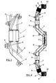
Figure 1 shows a representation according to a general perspective view of the duct carried out according to the object of the invention. -
Figure 2 shows an enlarged detail of the right end corresponding to the duct shown in the previous figure to allow clearly seeing the features of the corrugated sections and the opening for coupling the duct to the corresponding diffusers of the automobile. -
Figure 3 shows a schematic plan view of part of the duct in which the corresponding anchoring tabs or flanges can be seen. -
Figure 4 shows a plan view of the duct of the invention showing the symmetry thereof. -
Figure 5 finally shows the way of coupling the duct to one of the lateral diffusers provided in the corresponding automotive vehicle. - As can be seen in the mentioned figures, the duct (1) of the invention is formed as a one-piece body and has an elongated and symmetrical configuration with a central section (2) which is rigid and is provided with the corresponding outlets (3) for its coupling to the central diffusers of the dashboard of a vehicle. This central section (2) is rigid and extends at its ends into respective divergent sections (4) which are also rigid and provided with tabs or flanges (5) with a double opening (6), as shown in
Figure 3 , for anchoring the duct in vehicles both right-hand steering and left-hand steering. - These divergent rigid sections (4) extend into two lateral sections (7) with an initial part and an end part thereof determined by small corrugated sections (8) such that the intermediate part (7) of these lateral sections is rigid, whereas the corrugated sections (8) make the deformability of the duct possible in these areas for adapting it in its assembly on the vehicle, collaborating in the duct other likewise corrugated sections provided in a bent end section (9) into which the outermost corrugated sections of the lateral sections (7) extend, these corrugated sections of the bends (9) being finished in openings (10) for coupling to the corresponding lateral diffusers (11) of the dashboard of the vehicle.
- The mentioned rigid sections (4) and (7) include, in addition to the tabs or flanges (5) with their double openings(6), other flanges (5'), provided with an opening to collaborate in anchoring the duct on the vehicle.
Claims (2)
- An air distribution duct for automotive vehicles provided for its coupling to the central and lateral diffusers of the dashboard of an automotive vehicle, forming part of the corresponding ventilation system, characterized in that it is formed by a one-piece body (1) provided with six deformable corrugated sections (8), making a small movement of part of the duct possible for its adaptability in the coupling on the central and lateral diffusers of the vehicle in question; anchoring means having been provided indistinctly making its assembly possible in vehicles with right-hand steering and in vehicles with left-hand steering.
- An air distribution duct for automotive vehicles according to claim 1, characterized in that the one-piece body has an elongated configuration like a yoke with a rigid central section (2) in which the outlets (3) for coupling to the central diffusers of the vehicle are provided, followed by two divergent sections (4) with tabs (5) having double openings (8) to allow assembly in vehicles with right-hand steering and with left-hand steering, the divergent sections of which continue into respective straight lateral sections (7), each of which has corrugated end parts (8), said straight lateral sections continuing into respective bends (9) with their corrugated end part (8) and its opening (10) for coupling to the lateral diffusers of the vehicle.
Applications Claiming Priority (1)
| Application Number | Priority Date | Filing Date | Title |
|---|---|---|---|
| ES200602796U ES1064483Y (en) | 2006-12-28 | 2006-12-28 | AIR DISTRIBUTION TUBE FOR AUTOMOBILE VEHICLES |
Publications (1)
| Publication Number | Publication Date |
|---|---|
| EP1939021A1 true EP1939021A1 (en) | 2008-07-02 |
Family
ID=38293856
Family Applications (1)
| Application Number | Title | Priority Date | Filing Date |
|---|---|---|---|
| EP07380388A Withdrawn EP1939021A1 (en) | 2006-12-28 | 2007-12-27 | Air distribution duct for automotive vehicles |
Country Status (2)
| Country | Link |
|---|---|
| EP (1) | EP1939021A1 (en) |
| ES (1) | ES1064483Y (en) |
Cited By (3)
| Publication number | Priority date | Publication date | Assignee | Title |
|---|---|---|---|---|
| EP2204297A3 (en) * | 2008-12-30 | 2010-08-04 | Seat, S.A. | Mounting system of an air conditioning equipment in a vehicle front dashboard |
| FR3095987A1 (en) * | 2019-05-16 | 2020-11-20 | Renault S.A.S. | AUTOMOTIVE VEHICLE AERAULIC DEVICE |
| IT202100016115A1 (en) * | 2021-06-21 | 2022-12-21 | Denso Thermal Systems Spa | Air conditioning unit with foldable and foldable air distribution pipes |
Citations (5)
| Publication number | Priority date | Publication date | Assignee | Title |
|---|---|---|---|---|
| DE3510336A1 (en) * | 1985-03-22 | 1986-10-02 | Adam Opel AG, 6090 Rüsselsheim | Air duct for motor vehicles |
| EP0756955A2 (en) * | 1995-08-04 | 1997-02-05 | Ford Motor Company | Air-handling system for automotive vehicles |
| DE19747646A1 (en) * | 1997-10-29 | 1999-05-06 | Behr Gmbh & Co | Vehicle interior air-conditioning with emitters and connected air channel |
| GB2332887A (en) * | 1997-11-19 | 1999-07-07 | Textron Automotive U K | Fluid reservoir and air duct |
| US20030083006A1 (en) * | 2001-10-31 | 2003-05-01 | Christian Brancheriau | Method for producing two fascias using two ventilation structures |
-
2006
- 2006-12-28 ES ES200602796U patent/ES1064483Y/en not_active Expired - Fee Related
-
2007
- 2007-12-27 EP EP07380388A patent/EP1939021A1/en not_active Withdrawn
Patent Citations (5)
| Publication number | Priority date | Publication date | Assignee | Title |
|---|---|---|---|---|
| DE3510336A1 (en) * | 1985-03-22 | 1986-10-02 | Adam Opel AG, 6090 Rüsselsheim | Air duct for motor vehicles |
| EP0756955A2 (en) * | 1995-08-04 | 1997-02-05 | Ford Motor Company | Air-handling system for automotive vehicles |
| DE19747646A1 (en) * | 1997-10-29 | 1999-05-06 | Behr Gmbh & Co | Vehicle interior air-conditioning with emitters and connected air channel |
| GB2332887A (en) * | 1997-11-19 | 1999-07-07 | Textron Automotive U K | Fluid reservoir and air duct |
| US20030083006A1 (en) * | 2001-10-31 | 2003-05-01 | Christian Brancheriau | Method for producing two fascias using two ventilation structures |
Cited By (4)
| Publication number | Priority date | Publication date | Assignee | Title |
|---|---|---|---|---|
| EP2204297A3 (en) * | 2008-12-30 | 2010-08-04 | Seat, S.A. | Mounting system of an air conditioning equipment in a vehicle front dashboard |
| FR3095987A1 (en) * | 2019-05-16 | 2020-11-20 | Renault S.A.S. | AUTOMOTIVE VEHICLE AERAULIC DEVICE |
| IT202100016115A1 (en) * | 2021-06-21 | 2022-12-21 | Denso Thermal Systems Spa | Air conditioning unit with foldable and foldable air distribution pipes |
| EP4108486A1 (en) * | 2021-06-21 | 2022-12-28 | DENSO THERMAL SYSTEMS S.p.A. | An air conditioning unit with deployable and collapsible air distribution pipes |
Also Published As
| Publication number | Publication date |
|---|---|
| ES1064483Y (en) | 2007-06-16 |
| ES1064483U (en) | 2007-03-16 |
Similar Documents
| Publication | Publication Date | Title |
|---|---|---|
| US8662457B2 (en) | Grommeted clamp assembly | |
| US6955394B1 (en) | Structural component for a motor vehicle | |
| CN104864008A (en) | Elastically averaged alignment systems and methods | |
| EP1939021A1 (en) | Air distribution duct for automotive vehicles | |
| CN104712619A (en) | Elastically averaged alignment systems and methods thereof | |
| CN109311070A (en) | System and method for design and manufacture of arcs and joints | |
| ATE253473T1 (en) | MOTION CONTROL SYSTEM FOR ONE OR MORE MOTOR VEHICLE SEATS | |
| US5113748A (en) | Defroster construction for automotive air conditioner | |
| DE202020107497U1 (en) | Vehicle cockpit module assembly | |
| US20180272841A1 (en) | Integrated roof bow and hvac duct with a headliner providing a close-out wall of the duct | |
| CN107031341B (en) | Blending-Promoting Temperature Doors for HVAC | |
| JP6399286B2 (en) | Vehicle air conditioner | |
| KR100191134B1 (en) | Air conditioning duct structure for automobile | |
| US20060199492A1 (en) | Airflow distribution structure of vehicle air conditioning system | |
| EP2181911B1 (en) | Heat formed component and method for manufacturing same | |
| CN207889833U (en) | Dashboard cross member and automobile | |
| US7637514B2 (en) | Mounting structure of a rear suspension cross member of a vehicle | |
| JP4252259B2 (en) | Air conditioning duct structure for vehicles | |
| CN208411876U (en) | A front end frame and vehicle | |
| WO1999030945A9 (en) | Master cylinder | |
| JP2000108637A (en) | Automotive air-conditioning duct structure | |
| EP3854654B1 (en) | Air distribution system for a vehicle, hvac system for a vehicle comprising such air distribution system, and related vehicle | |
| JP4375272B2 (en) | Method for manufacturing duct body | |
| JP7739861B2 (en) | Instrument panel support structure | |
| CN220390928U (en) | Air-out system of automobile air conditioner and automobile |
Legal Events
| Date | Code | Title | Description |
|---|---|---|---|
| PUAI | Public reference made under article 153(3) epc to a published international application that has entered the european phase |
Free format text: ORIGINAL CODE: 0009012 |
|
| AK | Designated contracting states |
Kind code of ref document: A1 Designated state(s): AT BE BG CH CY CZ DE DK EE ES FI FR GB GR HU IE IS IT LI LT LU LV MC MT NL PL PT RO SE SI SK TR |
|
| AX | Request for extension of the european patent |
Extension state: AL BA HR MK RS |
|
| 17P | Request for examination filed |
Effective date: 20081224 |
|
| AKX | Designation fees paid |
Designated state(s): AT BE BG CH CY CZ DE DK EE ES FI FR GB GR HU IE IS IT LI LT LU LV MC MT NL PL PT RO SE SI SK TR |
|
| 17Q | First examination report despatched |
Effective date: 20090218 |
|
| STAA | Information on the status of an ep patent application or granted ep patent |
Free format text: STATUS: THE APPLICATION IS DEEMED TO BE WITHDRAWN |
|
| 18D | Application deemed to be withdrawn |
Effective date: 20090829 |