EP1937575B1 - Conveyor belt with overlapping planar surface plates - Google Patents
Conveyor belt with overlapping planar surface plates Download PDFInfo
- Publication number
- EP1937575B1 EP1937575B1 EP06808858A EP06808858A EP1937575B1 EP 1937575 B1 EP1937575 B1 EP 1937575B1 EP 06808858 A EP06808858 A EP 06808858A EP 06808858 A EP06808858 A EP 06808858A EP 1937575 B1 EP1937575 B1 EP 1937575B1
- Authority
- EP
- European Patent Office
- Prior art keywords
- conveyor belt
- belt
- plates
- transport
- plate
- Prior art date
- Legal status (The legal status is an assumption and is not a legal conclusion. Google has not performed a legal analysis and makes no representation as to the accuracy of the status listed.)
- Active
Links
- 239000000463 material Substances 0.000 claims description 19
- 238000000034 method Methods 0.000 claims description 6
- 238000000926 separation method Methods 0.000 claims description 5
- 239000002184 metal Substances 0.000 claims description 2
- 229910052751 metal Inorganic materials 0.000 claims description 2
- 229910001018 Cast iron Inorganic materials 0.000 description 4
- RTZKZFJDLAIYFH-UHFFFAOYSA-N Diethyl ether Chemical compound CCOCC RTZKZFJDLAIYFH-UHFFFAOYSA-N 0.000 description 2
- 238000005266 casting Methods 0.000 description 2
- 238000010276 construction Methods 0.000 description 2
- 238000001816 cooling Methods 0.000 description 2
- 238000004519 manufacturing process Methods 0.000 description 2
- 238000000465 moulding Methods 0.000 description 2
- 238000006467 substitution reaction Methods 0.000 description 2
- 239000002699 waste material Substances 0.000 description 2
- 229910000831 Steel Inorganic materials 0.000 description 1
- 230000006978 adaptation Effects 0.000 description 1
- 230000005540 biological transmission Effects 0.000 description 1
- 230000008878 coupling Effects 0.000 description 1
- 238000010168 coupling process Methods 0.000 description 1
- 238000005859 coupling reaction Methods 0.000 description 1
- 230000006866 deterioration Effects 0.000 description 1
- 230000003203 everyday effect Effects 0.000 description 1
- 229920001903 high density polyethylene Polymers 0.000 description 1
- 239000004700 high-density polyethylene Substances 0.000 description 1
- 230000010354 integration Effects 0.000 description 1
- 238000003754 machining Methods 0.000 description 1
- 238000012986 modification Methods 0.000 description 1
- 230000004048 modification Effects 0.000 description 1
- 239000004033 plastic Substances 0.000 description 1
- 229920003023 plastic Polymers 0.000 description 1
- 239000010959 steel Substances 0.000 description 1
Images


Classifications
-
- B—PERFORMING OPERATIONS; TRANSPORTING
- B65—CONVEYING; PACKING; STORING; HANDLING THIN OR FILAMENTARY MATERIAL
- B65G—TRANSPORT OR STORAGE DEVICES, e.g. CONVEYORS FOR LOADING OR TIPPING, SHOP CONVEYOR SYSTEMS OR PNEUMATIC TUBE CONVEYORS
- B65G17/00—Conveyors having an endless traction element, e.g. a chain, transmitting movement to a continuous or substantially-continuous load-carrying surface or to a series of individual load-carriers; Endless-chain conveyors in which the chains form the load-carrying surface
- B65G17/06—Conveyors having an endless traction element, e.g. a chain, transmitting movement to a continuous or substantially-continuous load-carrying surface or to a series of individual load-carriers; Endless-chain conveyors in which the chains form the load-carrying surface having a load-carrying surface formed by a series of interconnected, e.g. longitudinal, links, plates, or platforms
- B65G17/065—Conveyors having an endless traction element, e.g. a chain, transmitting movement to a continuous or substantially-continuous load-carrying surface or to a series of individual load-carriers; Endless-chain conveyors in which the chains form the load-carrying surface having a load-carrying surface formed by a series of interconnected, e.g. longitudinal, links, plates, or platforms the load carrying surface being formed by plates or platforms attached to a single traction element
-
- B—PERFORMING OPERATIONS; TRANSPORTING
- B65—CONVEYING; PACKING; STORING; HANDLING THIN OR FILAMENTARY MATERIAL
- B65G—TRANSPORT OR STORAGE DEVICES, e.g. CONVEYORS FOR LOADING OR TIPPING, SHOP CONVEYOR SYSTEMS OR PNEUMATIC TUBE CONVEYORS
- B65G17/00—Conveyors having an endless traction element, e.g. a chain, transmitting movement to a continuous or substantially-continuous load-carrying surface or to a series of individual load-carriers; Endless-chain conveyors in which the chains form the load-carrying surface
- B65G17/06—Conveyors having an endless traction element, e.g. a chain, transmitting movement to a continuous or substantially-continuous load-carrying surface or to a series of individual load-carriers; Endless-chain conveyors in which the chains form the load-carrying surface having a load-carrying surface formed by a series of interconnected, e.g. longitudinal, links, plates, or platforms
- B65G17/067—Conveyors having an endless traction element, e.g. a chain, transmitting movement to a continuous or substantially-continuous load-carrying surface or to a series of individual load-carriers; Endless-chain conveyors in which the chains form the load-carrying surface having a load-carrying surface formed by a series of interconnected, e.g. longitudinal, links, plates, or platforms the load carrying surface being formed by plates or platforms attached to more than one traction element
Definitions
- the present invention is about a metallic conveyor belt with overlapping planar surface plates, and a method of use of such a belt.
- conveyor belts of this kind are disclosed in United States Patents Nos. 3.633.737 , which discloses the preamble of claim 1, and 3.749.228, where material holding means overlap each other to form a continuous channel in which the material can be held and carried.
- the transport surface is not planar having steps corresponding to the overlapping zone of the material holding means.
- the overlapping of plates generates a non planar surface, caused by partial imbricated overlapping of the plates in the direction of motion.
- Such embodiment constitutes a limit to the increase in thickness of the plates and therefore to the sturdiness of the assembly, due to the growing difficulty with the thickness of the plates, to slide on the return wheels.
- the presence of small steps causes a waste of power due to the energy absorbed to raise the conveyor belt at every passage of the small steps on the return wheels. This energy waste, besides, produces vibrations or noise.
- the non planar surface of the conveyor belt on the load bearing section causes, in practice, hindrance to positioning deviators on the conveyor belt to laterally discharge transported materials, which would get stuck between the small steps formed by the overlapping of the plates and the deviator.
- the conveyor belt 1 object of this invention compared to a conveyor belt of known construction, provides a particular construction of the plates 2 such as the relative position between two consecutive plates makes the transport surface planar and continuous, turning it into a sturdy and reliable moving plane. This is particularly evident with reference to Figure 1 of the attached drawings.
- the conveyor belt 1 according to the present invention is able to operate even in the presence of extreme mechanical stress, deriving for example from the impact of heavy weights on the belt or mechanical stress due to working performed on the belt.
- the conveyor belt 1 comprises a metallic net belt 8 ( Figures 1A and 1B ) representing the principal traction element, to which the plates 2 are fixed by means of screws 7, bolts or rivets and corresponding bored plaques 9, each of these bored plaques 9 being thereby inserted inside a mesh of the traction net 8.
- the shape of each plate 2, partially overlapping the following one, allows to attain a planar and continuous transport surface, keeping it closed to protect the supporting belt 8 even during rotation on the traction drum 5 and the return drum 12.
- the conveyor belt 1 thus set up is operated by the traction drum 5, it is tensioned by the return drum 12, the latter assuring the necessary constant tension, and is supported by a plurality of transversal independent rollers 13, supporting the belt on the upper section and by wheels (not shown), supporting the belt on the return section.
- planarity of the transport surface allows for the application of one or more deviators 11 and/or separation baffles 16, allowing to differentiate the transported material according to production requirements, avoiding the material to get stuck between the belt and the deviators 11, with subsequent abrupt stops of the conveyor belt.
- An advantage deriving from the planarity of the transport surface and absence of vibrations is the possibility to transport components, like mould parts of the vertical moulding line during the cooling phase of cast iron, without damaging the mould part, nor the conveyor belt due to accidental spilling of cast iron during transport.
- the absolute sturdiness of the plane, the absence of vibrations and the perfectly planar surface without protrusions cause the conveyor belt according to the invention to be fit to be used as a mobile walkway, possibly even in association with working performed by personnel transported by the belt.
- One embodiment of the conveyor belt 1 is obtained by coupling two plates 3 and 4 of different shape, fixing them by couples by means of bolts, screws or rivets 7 to corresponding bored plaques 9 inserted inside the metal net 8, where the upper plate 3 results partially overlapping over the following base plate 4. Plates 3 and 4 thus coupled stay integral and form a single body even when wrapping on drums 5.
- the bores on the lower plate 4 are slotted to allow for a differential expansion between the plates 3 and 4 due to different thermal conditions.
- elements 3 and 4 may be of different thickness and different material from each other, allowing for both the ideal choice for the material in contact with the product to be transported, and the choice of the total thickness necessary to convey sturdiness to the conveyor belt according to transport needs.
- the conveyor belt object of this invention can be considerably sturdier than those according to prior art, because this configuration with coupled plates 3 and 4 fixed to the net traction belt 8 allows to use considerable thickness without any difficulty in sliding on the return wheels 14.
- the close pitchof the load bearing rollers 13 gives sturdiness and reliability to the conveyor belt 1, absorbing possible impacts deriving for example by heavy weights hitting the conveyor belt 1.
- the resistance to mechanical stress of the high thickness overlapping plates 3 and 4 system, with close load bearing rollers 13, is further increased adopting supports 15 of the load bearing rollers provided with a breaking up point 14 with a calibrated resistance. These supports 15 allow to protect belt 1 from any mechanical stress, as they brake at the predetermined point when admitted stress is exceeded.
- Another embodiment of the conveyor belt 1 is that of making the plates 2 in one single piece, by machining or moulding, and they can further be made of plastic material, for example high density polyethylene, when it is necessary to warrant a low friction coefficient and when the materials to be transported are cold and not excessively abrasive.
- plastic material for example high density polyethylene
- the conveyor belt 1 can provide for lateral tabs 10 constituting extensions of the plates 2 which are turned ether upwards ( Figure 4 ) or downwards ( Figure 1 ).
- the function of tabs 10 turned upwards ( Figure 4 ) is suitable to contain the transported material in case it is loose or small sized.
- the configuration with tabs 10 turned downwards ( Figure 1 ) is suitable in case a lateral discharge is required, by applying suitable deviators 11 or by action of the operator, allowing to simply push the workpieces towards the discharge points without the necessity to lift them.
Landscapes
- Engineering & Computer Science (AREA)
- Mechanical Engineering (AREA)
- Structure Of Belt Conveyors (AREA)
- Belt Conveyors (AREA)
- Escalators And Moving Walkways (AREA)
Description
- The present invention is about a metallic conveyor belt with overlapping planar surface plates, and a method of use of such a belt.
- It is common practice, by now, in transporting difficult material, especially at high temperatures, use of a kind of metallic belt conveyor comprising a metallic net traction element supporting a plurality of partially overlapping steel plates, such as to form an almost sealed load bearing channel. Each plate is subsequently individually fixed by a plurality of bolts, screws or rivets inserted in corresponding bored plaques, each of these plaques being in turn inserted inside the meshes of the traction net conveyor belt. The conveyor belt thus comprised is operated by a traction drum, it is tensioned by a transmission drum, ensuring the necessary tension, and is supported by a plurality of independent transversal rollers, supporting the conveyor belt on its load bearing section, and by wheels supporting the belt in its return section. Examples of conveyor belts of this kind are disclosed in United States Patents Nos.
3.633.737 , which discloses the preamble of claim 1, and 3.749.228, where material holding means overlap each other to form a continuous channel in which the material can be held and carried. However the transport surface is not planar having steps corresponding to the overlapping zone of the material holding means. - In conveyor belts according to prior art, the overlapping of plates generates a non planar surface, caused by partial imbricated overlapping of the plates in the direction of motion. Such embodiment constitutes a limit to the increase in thickness of the plates and therefore to the sturdiness of the assembly, due to the growing difficulty with the thickness of the plates, to slide on the return wheels. The presence of small steps causes a waste of power due to the energy absorbed to raise the conveyor belt at every passage of the small steps on the return wheels. This energy waste, besides, produces vibrations or noise.
- The non planar surface of the conveyor belt on the load bearing section causes, in practice, hindrance to positioning deviators on the conveyor belt to laterally discharge transported materials, which would get stuck between the small steps formed by the overlapping of the plates and the deviator.
- For similar reasons, it is impossible to create more channels on the same conveyor belt for the possible choice and separation of the transported material.
- Moreover, an example of conveyor characterized by a planar transport surface is disclosed in United States Patent No.
3.311.222 , where load carrying members are bracketed to cables at each side of the conveyor frame, said carrying members having marginal side portions that allow meshing on the driving sprocket drum. - The above mentioned limits are overcome by the conveyor belt according to claim 1, whose planar surface, does not create obstacles In applying deviation and/or separation devices and is able to operate as a mobile work plane, attaining handling reliabilty even in the presence of extreme mechanical stress, as well as a method of use of such a waveyor belt as set out in claim 6.
- In everyday practice of vertical mould lines, the cooling of the casting in mould parts, as it requires to be performed in absence of any vibration, rubber conveyor belts are used positioned just downstream of the casting point of the cast iron. During transport of the mould parts, the rubber belt undergoes severe early deterioration caused by the leakage of the cast iron which spills out in case of possible damage of the mould parts, with resulting production down time. These problems can be totally eliminated by the conveyor belt object of this invention, whose planar high temperature proof transport surface and its absence of vibration allow for a safe transport of the mould parts, without damaging them.
- The absolute stiffness of the plane, the absence of vibrations and the perfectly flat planar surface make this invention fit to be used as a moving walkways, possibly even in association with working performed by personnel transported by the conveyor belt.
- The innovative features, aims and advantages of the present invention will become apparent from the following description and attached drawings, relating to non limitative embodiments, in which:
-
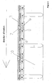
Figure 1 is a partial sectional view of the conveyor belt according to the present invention, including the traction and return drums and load bearing rollers; -
Figure 1A is a view in detail of the plates of the conveyor belt ofFigure 1 ; -
Figure 2 represents a schematic view of the conveyor belt wrapping on the drum; -
Figure 2B is a view in detail of the wrapping phase ofFigure 2 ; -
Figure 3 is a cross sectional view of the conveyor belt according to the invention; -
Figure 4 is a front sectional view of the conveyor belt with its support calibrated; and -
Figure 5 represents a schematic view of the close roller pitch. - In this respect it is hereby noted that identical reference numbers in the various figures indicate identical or equivalent parts.
- The conveyor belt 1 object of this invention, compared to a conveyor belt of known construction, provides a particular construction of the
plates 2 such as the relative position between two consecutive plates makes the transport surface planar and continuous, turning it into a sturdy and reliable moving plane. This is particularly evident with reference toFigure 1 of the attached drawings. - The conveyor belt 1 according to the present invention is able to operate even in the presence of extreme mechanical stress, deriving for example from the impact of heavy weights on the belt or mechanical stress due to working performed on the belt.
- The conveyor belt 1 comprises a metallic net belt 8 (
Figures 1A and 1B ) representing the principal traction element, to which theplates 2 are fixed by means ofscrews 7, bolts or rivets and correspondingbored plaques 9, each of thesebored plaques 9 being thereby inserted inside a mesh of the traction net 8. The shape of eachplate 2, partially overlapping the following one, allows to attain a planar and continuous transport surface, keeping it closed to protect the supportingbelt 8 even during rotation on the traction drum 5 and thereturn drum 12. - The conveyor belt 1 thus set up is operated by the traction drum 5, it is tensioned by the
return drum 12, the latter assuring the necessary constant tension, and is supported by a plurality of transversalindependent rollers 13, supporting the belt on the upper section and by wheels (not shown), supporting the belt on the return section. - The planarity of the transport surface allows for the application of one or more deviators 11 and/or
separation baffles 16, allowing to differentiate the transported material according to production requirements, avoiding the material to get stuck between the belt and the deviators 11, with subsequent abrupt stops of the conveyor belt. - An advantage deriving from the planarity of the transport surface and absence of vibrations is the possibility to transport components, like mould parts of the vertical moulding line during the cooling phase of cast iron, without damaging the mould part, nor the conveyor belt due to accidental spilling of cast iron during transport.
- Additionally, the absolute sturdiness of the plane, the absence of vibrations and the perfectly planar surface without protrusions cause the conveyor belt according to the invention to be fit to be used as a mobile walkway, possibly even in association with working performed by personnel transported by the belt.
- One embodiment of the conveyor belt 1 is obtained by coupling two
plates rivets 7 to correspondingbored plaques 9 inserted inside themetal net 8, where theupper plate 3 results partially overlapping over the followingbase plate 4.Plates lower plate 4 are slotted to allow for a differential expansion between theplates - In case of such realization of
plates 2,elements - For this reason, the conveyor belt object of this invention can be considerably sturdier than those according to prior art, because this configuration with coupled
plates net traction belt 8 allows to use considerable thickness without any difficulty in sliding on thereturn wheels 14. The close pitchof theload bearing rollers 13 gives sturdiness and reliability to the conveyor belt 1, absorbing possible impacts deriving for example by heavy weights hitting the conveyor belt 1. - The resistance to mechanical stress of the high
thickness overlapping plates load bearing rollers 13, is further increased adoptingsupports 15 of the load bearing rollers provided with a breaking uppoint 14 with a calibrated resistance. these supports 15 allow to protect belt 1 from any mechanical stress, as they brake at the predetermined point when admitted stress is exceeded. - Since the pitch of the load bearing 13 is close, the possible break up of one or
more supports 15 will be non influential on the normal running of the conveyor belt 1 and the substitution ofsupports 15 andrelevant rollers 13 can be performed without the necessity to stop the conveyor belt 1. - Another embodiment of the conveyor belt 1 is that of making the
plates 2 in one single piece, by machining or moulding, and they can further be made of plastic material, for example high density polyethylene, when it is necessary to warrant a low friction coefficient and when the materials to be transported are cold and not excessively abrasive. - According to transport needs and kind of material, the conveyor belt 1 can provide for
lateral tabs 10 constituting extensions of theplates 2 which are turned ether upwards (Figure 4 ) or downwards (Figure 1 ). In particular, the function oftabs 10 turned upwards (Figure 4 ) is suitable to contain the transported material in case it is loose or small sized. The configuration withtabs 10 turned downwards (Figure 1 ) is suitable in case a lateral discharge is required, by applying suitable deviators 11 or by action of the operator, allowing to simply push the workpieces towards the discharge points without the necessity to lift them. - It is apparent that to the embodiments described in this application by way of example and in a non limitative way, many modifications, adaptation, integrations, changes and substitutions of elements with functionally equivalent others may be performed, without falling out of the scope as defined by the following claims.
Claims (9)
- A conveyor belt (1), comprising a metallic net belt (8) operated by at least a traction drum (5), tensioned by at least a return drum (12) and supported by a plurality of independent transversal rollers (13), said belt (1) supporting individually a plurality of plates (2) partially overlapping one another, so as to form a flat continuous surface as a mobile reliable plane resistant to extreme mechanical stress, wherein each of said plates (2) is suitably shaped so that the upper part of one plate overlaps the lower part of the following plate,
characterised in that each of said plates (2) is made by an upper element (3) and a base element (4) partially overlapped one to other in a staggered arrangement, of which the upper element (3) is partially overlapping the base element of the following plate and the base element (4) is partially underlying the upper element of the preceding plate, so as to form a continuous surface protecting the supporting belt (8) even when travelling around the drums (5, 12), which plate (2) is made by a suitably-shaped single piece or by two distinct elements (3, 4). - The conveyor belt (1) according to claim 1, where the elements (3, 4) are fixed by couple by means of a plurality of bolts, screws or rivets (7) to a plurality of plaques (9) inserted inside the metal net (8).
- The conveyor belt (1) according to claim 1, where the plates (2) are provided with lateral tabs (10), turned upwards or downwards according to transport needs and kind of material transported.
- The conveyor belt according to claims 1 to 3, where supports (15) of the load bearing rollers (13) are provided with a breaking up point (14) with a calibrated resistance so that said supports (15) break at a predetemined point when admitted stress is exceeded.
- The conveyor belt according to any of claims 1 to 4, characterised by the presence of one or more deviators (11) and/or separation baffles (16) on the transport surface.
- A method of use of the conveyor belt (1) according to the preceding claims, where the mechanical stress due to the possible impact on the belt of the material transported is transferred to the supports (15) of the load bearing rollers (13) calibrated in such a way to break without affecting the continuity of motion of the conveyor belt (1).
- The method according to claim 6, where the plates (2) are made of a material which is metallic, synthetic or organic, and provided with one or more deviators (11) allowing the lateral discharge of the material transported and/or channels to achieve the separation on the conveyor belt (1) of materials or objects of different nature.
- The method according to claims 6 and 7, where the absence of vibration and the presence of plates (2) partially overlapping to form a flat continuous surface allow the transport of particular components, like mould parts, without damaging them during transport.
- The method according to claim 7, where the belt (1) can be also used for transporting people, which can possibly perform operation during the motion of the conveyor belt (1).
Priority Applications (1)
| Application Number | Priority Date | Filing Date | Title |
|---|---|---|---|
| PL06808858T PL1937575T3 (en) | 2005-09-21 | 2006-09-20 | Conveyor belt with overlapping planar surface plates |
Applications Claiming Priority (2)
| Application Number | Priority Date | Filing Date | Title |
|---|---|---|---|
| IT001745A ITMI20051745A1 (en) | 2005-09-21 | 2005-09-21 | CONVEYOR BELT WITH PLACES OVERLAY WITH FLAT SURFACE |
| PCT/IB2006/002589 WO2007034289A1 (en) | 2005-09-21 | 2006-09-20 | Conveyor belt with overlapping planar surface plates |
Publications (2)
| Publication Number | Publication Date |
|---|---|
| EP1937575A1 EP1937575A1 (en) | 2008-07-02 |
| EP1937575B1 true EP1937575B1 (en) | 2012-12-12 |
Family
ID=37671914
Family Applications (1)
| Application Number | Title | Priority Date | Filing Date |
|---|---|---|---|
| EP06808858A Active EP1937575B1 (en) | 2005-09-21 | 2006-09-20 | Conveyor belt with overlapping planar surface plates |
Country Status (15)
| Country | Link |
|---|---|
| US (1) | US7958991B2 (en) |
| EP (1) | EP1937575B1 (en) |
| JP (1) | JP5144520B2 (en) |
| KR (1) | KR101409197B1 (en) |
| CN (1) | CN101267997A (en) |
| AU (1) | AU2006293582B2 (en) |
| BR (1) | BRPI0617593B1 (en) |
| CA (1) | CA2622863A1 (en) |
| DK (1) | DK1937575T3 (en) |
| EA (1) | EA013277B1 (en) |
| ES (1) | ES2402731T3 (en) |
| IT (1) | ITMI20051745A1 (en) |
| PL (1) | PL1937575T3 (en) |
| PT (1) | PT1937575E (en) |
| WO (1) | WO2007034289A1 (en) |
Families Citing this family (17)
| Publication number | Priority date | Publication date | Assignee | Title |
|---|---|---|---|---|
| DE102009040773A1 (en) * | 2009-09-09 | 2011-03-10 | Krones Ag | conveyor belt |
| IT1396049B1 (en) * | 2009-09-24 | 2012-11-09 | Magaldi Ind Srl | ASH EXTRACTION AND TRANSPORTATION SYSTEM READ THROUGH THE STEEL TAPE CONVEYOR. |
| CN101920836A (en) * | 2010-09-06 | 2010-12-22 | 宜都中起重工机械有限公司 | Ultra-wide apron conveyer |
| US8561791B2 (en) | 2010-10-26 | 2013-10-22 | Pratt & Whitney Rocketdyne, Inc. | Balanced link for dry coal extrusion pumps |
| US20130104873A1 (en) * | 2011-06-30 | 2013-05-02 | Daniel S. Henry | Pellet furnace |
| JP2013224189A (en) * | 2012-04-20 | 2013-10-31 | Nippon Electric Glass Co Ltd | Belt conveyer |
| EP3003215A4 (en) * | 2013-06-07 | 2017-02-22 | The Regents of the University of California | Transplantation device and method of use |
| WO2015010894A1 (en) * | 2013-07-26 | 2015-01-29 | Inventio Ag | Pallet of a moving walkway |
| EP3237174B1 (en) | 2014-12-22 | 2019-03-20 | 3M Innovative Properties Company | Apparatus and method for stretching and taking-away polymer films |
| ITUB20152285A1 (en) * | 2015-07-17 | 2017-01-17 | Magaldi Ind Srl | CONVEYOR TRANSPORT SYSTEM FOR LARGE LOOSE MATERIAL FLOWS |
| US10308436B2 (en) | 2015-12-16 | 2019-06-04 | Laitram, L.L.C. | Modular conveyor belt with attached plates |
| DE102016105008B3 (en) * | 2016-03-17 | 2017-08-24 | Chuan Yang Foods Machine Co., Ltd. | Anti-stick conveyor belt and conveyor strip of a fryer |
| CN109641775A (en) * | 2016-06-17 | 2019-04-16 | 堺显示器制品株式会社 | Bender |
| IT202000007063A1 (en) | 2020-04-03 | 2021-10-03 | Magaldi Power Spa | SYSTEM AND METHOD FOR THE THERMAL PROCESSING OF BULK MATERIAL BY CONCENTRATED INTENSE SOLAR POWER |
| US11142414B1 (en) * | 2020-05-07 | 2021-10-12 | Buckeye Corrugated, Inc. | Method and article for standing on roller conveyor |
| MX2023005718A (en) | 2020-11-16 | 2023-05-25 | Magaldi Power Spa | Fluidized bed heat exchanger and method. |
| CN113413953A (en) * | 2021-04-30 | 2021-09-21 | 重庆市永安工程建设监理有限公司 | Reducing mechanism is used in engineering construction supervision |
Family Cites Families (15)
| Publication number | Priority date | Publication date | Assignee | Title |
|---|---|---|---|---|
| US2954113A (en) * | 1957-01-09 | 1960-09-27 | Chain Belt Co | Conveyer chain attachments |
| US3311222A (en) | 1965-05-20 | 1967-03-28 | Chemetron Corp | Conveyor |
| US3633737A (en) * | 1968-12-16 | 1972-01-11 | Paolo Magaldi | Conveyor, particularly for hot materials |
| US3653494A (en) * | 1970-05-14 | 1972-04-04 | Eldon S Miller | Articulated link conveyor |
| US3807548A (en) * | 1972-01-04 | 1974-04-30 | Europ Manutation | Conveyor link and conveyor chains made therefrom |
| US3749228A (en) * | 1972-06-14 | 1973-07-31 | P Magaldi | Protected belt conveyor |
| US4078654A (en) * | 1976-05-10 | 1978-03-14 | The Sardee Corporation | Flexible coated wire cable conveyor structure |
| JPS611132Y2 (en) * | 1979-01-19 | 1986-01-16 | ||
| IT1188247B (en) * | 1986-01-10 | 1988-01-07 | Magaldi Mario | PROCEDURE AND EQUIPMENT FOR THE CONTINUOUS DRY EXTRACTION OF HEAVY ASH |
| JPS63247207A (en) * | 1987-04-03 | 1988-10-13 | Bridgestone Corp | Conveyor belt supporting device |
| JP3218412B2 (en) * | 1992-11-09 | 2001-10-15 | アサヒ装設株式会社 | Net conveyor for flyers |
| JPH09156740A (en) * | 1995-12-14 | 1997-06-17 | Suzuki Motor Corp | Slat conveyor |
| NL1002039C2 (en) * | 1996-01-08 | 1997-07-09 | Vanderlande Ind Nederland | Transport device. |
| JPH11227922A (en) * | 1998-02-19 | 1999-08-24 | Daifuku Co Ltd | Slat conveyer |
| ITMI20040014U1 (en) * | 2004-01-20 | 2004-04-20 | Regina Sud Spa | TRANSPORT CHAIN PERFECTED |
-
2005
- 2005-09-21 IT IT001745A patent/ITMI20051745A1/en unknown
-
2006
- 2006-09-20 EA EA200800636A patent/EA013277B1/en not_active IP Right Cessation
- 2006-09-20 DK DK06808858.2T patent/DK1937575T3/en active
- 2006-09-20 JP JP2008531804A patent/JP5144520B2/en active Active
- 2006-09-20 WO PCT/IB2006/002589 patent/WO2007034289A1/en active Application Filing
- 2006-09-20 AU AU2006293582A patent/AU2006293582B2/en not_active Ceased
- 2006-09-20 ES ES06808858T patent/ES2402731T3/en active Active
- 2006-09-20 PL PL06808858T patent/PL1937575T3/en unknown
- 2006-09-20 EP EP06808858A patent/EP1937575B1/en active Active
- 2006-09-20 BR BRPI0617593-7A patent/BRPI0617593B1/en active IP Right Grant
- 2006-09-20 US US11/992,447 patent/US7958991B2/en active Active
- 2006-09-20 CN CNA2006800349603A patent/CN101267997A/en active Pending
- 2006-09-20 CA CA002622863A patent/CA2622863A1/en not_active Abandoned
- 2006-09-20 PT PT68088582T patent/PT1937575E/en unknown
- 2006-09-20 KR KR1020087008785A patent/KR101409197B1/en active IP Right Grant
Also Published As
| Publication number | Publication date |
|---|---|
| BRPI0617593A2 (en) | 2011-08-02 |
| DK1937575T3 (en) | 2013-03-25 |
| EA013277B1 (en) | 2010-04-30 |
| AU2006293582A1 (en) | 2007-03-29 |
| EP1937575A1 (en) | 2008-07-02 |
| JP2009508785A (en) | 2009-03-05 |
| AU2006293582B2 (en) | 2012-02-02 |
| BRPI0617593B1 (en) | 2018-01-16 |
| ITMI20051745A1 (en) | 2007-03-22 |
| PT1937575E (en) | 2013-03-18 |
| KR20080088573A (en) | 2008-10-02 |
| WO2007034289A1 (en) | 2007-03-29 |
| ES2402731T3 (en) | 2013-05-08 |
| KR101409197B1 (en) | 2014-06-19 |
| CN101267997A (en) | 2008-09-17 |
| CA2622863A1 (en) | 2007-03-29 |
| PL1937575T3 (en) | 2013-08-30 |
| US7958991B2 (en) | 2011-06-14 |
| EA200800636A1 (en) | 2008-10-30 |
| US20100012456A1 (en) | 2010-01-21 |
| JP5144520B2 (en) | 2013-02-13 |
Similar Documents
| Publication | Publication Date | Title |
|---|---|---|
| EP1937575B1 (en) | Conveyor belt with overlapping planar surface plates | |
| CN102282062B (en) | Master link for a track chain | |
| EP0654398B1 (en) | Crawler | |
| US20080302631A1 (en) | Moving Walkway | |
| CN103476667A (en) | Tracked running gear | |
| CN110040616B (en) | Moving sidewalk | |
| JPS5825603B2 (en) | roller conveyor line | |
| AU2015261721B2 (en) | Tracked chassis and work machine having a track drive | |
| US4287983A (en) | Conveyors having a plurality of driven endless chains | |
| US5413451A (en) | Loading and unloading powered apparatus for trucks and the like | |
| EP2331445B1 (en) | People mover, transmission chain and method in the use of a people mover | |
| Dudziński et al. | Energy efficiency of rubber tracked chassis | |
| JP4671903B2 (en) | Track roller guard | |
| CA2860938C (en) | Spoke design for sheaves | |
| US6435628B1 (en) | Guiding arrangement for a track type work machine | |
| CN211919832U (en) | Automatic feeding device for laser jointed boards | |
| US3764185A (en) | Shoe for track chain assembly | |
| KR200448705Y1 (en) | conveyor belt system | |
| CN112533819A (en) | Attachable caterpillar panel cover | |
| KR0122162Y1 (en) | Conveyer belt system | |
| KR200399268Y1 (en) | Apparatus for preventing the conveyor belt from meandering | |
| CA3116134A1 (en) | Cast feeder pans, methods of casting same and uses therefore | |
| US20030122423A1 (en) | High stiffness track assembly for undercarriage noise reduction | |
| EP1593618A1 (en) | Chain conveyor guide | |
| EP2258653B1 (en) | A lifting chain assembly |
Legal Events
| Date | Code | Title | Description |
|---|---|---|---|
| PUAI | Public reference made under article 153(3) epc to a published international application that has entered the european phase |
Free format text: ORIGINAL CODE: 0009012 |
|
| 17P | Request for examination filed |
Effective date: 20080418 |
|
| AK | Designated contracting states |
Kind code of ref document: A1 Designated state(s): AT BE BG CH CY CZ DE DK EE ES FI FR GB GR HU IE IS IT LI LT LU LV MC NL PL PT RO SE SI SK TR |
|
| 17Q | First examination report despatched |
Effective date: 20090326 |
|
| GRAP | Despatch of communication of intention to grant a patent |
Free format text: ORIGINAL CODE: EPIDOSNIGR1 |
|
| DAX | Request for extension of the european patent (deleted) | ||
| GRAS | Grant fee paid |
Free format text: ORIGINAL CODE: EPIDOSNIGR3 |
|
| GRAA | (expected) grant |
Free format text: ORIGINAL CODE: 0009210 |
|
| AK | Designated contracting states |
Kind code of ref document: B1 Designated state(s): AT BE BG CH CY CZ DE DK EE ES FI FR GB GR HU IE IS IT LI LT LU LV MC NL PL PT RO SE SI SK TR |
|
| REG | Reference to a national code |
Ref country code: GB Ref legal event code: FG4D |
|
| REG | Reference to a national code |
Ref country code: CH Ref legal event code: EP |
|
| REG | Reference to a national code |
Ref country code: AT Ref legal event code: REF Ref document number: 588225 Country of ref document: AT Kind code of ref document: T Effective date: 20121215 |
|
| REG | Reference to a national code |
Ref country code: IE Ref legal event code: FG4D |
|
| REG | Reference to a national code |
Ref country code: DE Ref legal event code: R096 Ref document number: 602006033619 Country of ref document: DE Effective date: 20130131 |
|
| REG | Reference to a national code |
Ref country code: CH Ref legal event code: PCOW Free format text: NEW ADDRESS: VIA IRNO 219, 84135 SALERNO (IT) |
|
| REG | Reference to a national code |
Ref country code: PT Ref legal event code: SC4A Free format text: AVAILABILITY OF NATIONAL TRANSLATION Effective date: 20130312 |
|
| REG | Reference to a national code |
Ref country code: DK Ref legal event code: T3 |
|
| REG | Reference to a national code |
Ref country code: SE Ref legal event code: TRGR |
|
| REG | Reference to a national code |
Ref country code: NL Ref legal event code: T3 |
|
| PG25 | Lapsed in a contracting state [announced via postgrant information from national office to epo] |
Ref country code: FI Free format text: LAPSE BECAUSE OF FAILURE TO SUBMIT A TRANSLATION OF THE DESCRIPTION OR TO PAY THE FEE WITHIN THE PRESCRIBED TIME-LIMIT Effective date: 20121212 Ref country code: LT Free format text: LAPSE BECAUSE OF FAILURE TO SUBMIT A TRANSLATION OF THE DESCRIPTION OR TO PAY THE FEE WITHIN THE PRESCRIBED TIME-LIMIT Effective date: 20121212 |
|
| REG | Reference to a national code |
Ref country code: CH Ref legal event code: NV Representative=s name: PATENTANWAELTE SCHAAD, BALASS, MENZL AND PARTN, CH |
|
| REG | Reference to a national code |
Ref country code: ES Ref legal event code: FG2A Ref document number: 2402731 Country of ref document: ES Kind code of ref document: T3 Effective date: 20130508 |
|
| REG | Reference to a national code |
Ref country code: LT Ref legal event code: MG4D |
|
| PG25 | Lapsed in a contracting state [announced via postgrant information from national office to epo] |
Ref country code: GR Free format text: LAPSE BECAUSE OF FAILURE TO SUBMIT A TRANSLATION OF THE DESCRIPTION OR TO PAY THE FEE WITHIN THE PRESCRIBED TIME-LIMIT Effective date: 20130313 Ref country code: LV Free format text: LAPSE BECAUSE OF FAILURE TO SUBMIT A TRANSLATION OF THE DESCRIPTION OR TO PAY THE FEE WITHIN THE PRESCRIBED TIME-LIMIT Effective date: 20121212 Ref country code: SI Free format text: LAPSE BECAUSE OF FAILURE TO SUBMIT A TRANSLATION OF THE DESCRIPTION OR TO PAY THE FEE WITHIN THE PRESCRIBED TIME-LIMIT Effective date: 20121212 |
|
| PG25 | Lapsed in a contracting state [announced via postgrant information from national office to epo] |
Ref country code: EE Free format text: LAPSE BECAUSE OF FAILURE TO SUBMIT A TRANSLATION OF THE DESCRIPTION OR TO PAY THE FEE WITHIN THE PRESCRIBED TIME-LIMIT Effective date: 20121212 Ref country code: CY Free format text: LAPSE BECAUSE OF FAILURE TO SUBMIT A TRANSLATION OF THE DESCRIPTION OR TO PAY THE FEE WITHIN THE PRESCRIBED TIME-LIMIT Effective date: 20121212 Ref country code: SK Free format text: LAPSE BECAUSE OF FAILURE TO SUBMIT A TRANSLATION OF THE DESCRIPTION OR TO PAY THE FEE WITHIN THE PRESCRIBED TIME-LIMIT Effective date: 20121212 Ref country code: BG Free format text: LAPSE BECAUSE OF FAILURE TO SUBMIT A TRANSLATION OF THE DESCRIPTION OR TO PAY THE FEE WITHIN THE PRESCRIBED TIME-LIMIT Effective date: 20130312 Ref country code: IS Free format text: LAPSE BECAUSE OF FAILURE TO SUBMIT A TRANSLATION OF THE DESCRIPTION OR TO PAY THE FEE WITHIN THE PRESCRIBED TIME-LIMIT Effective date: 20130412 |
|
| PG25 | Lapsed in a contracting state [announced via postgrant information from national office to epo] |
Ref country code: RO Free format text: LAPSE BECAUSE OF FAILURE TO SUBMIT A TRANSLATION OF THE DESCRIPTION OR TO PAY THE FEE WITHIN THE PRESCRIBED TIME-LIMIT Effective date: 20121212 |
|
| REG | Reference to a national code |
Ref country code: PL Ref legal event code: T3 |
|
| PLBE | No opposition filed within time limit |
Free format text: ORIGINAL CODE: 0009261 |
|
| STAA | Information on the status of an ep patent application or granted ep patent |
Free format text: STATUS: NO OPPOSITION FILED WITHIN TIME LIMIT |
|
| PGFP | Annual fee paid to national office [announced via postgrant information from national office to epo] |
Ref country code: DK Payment date: 20130918 Year of fee payment: 8 Ref country code: PT Payment date: 20130312 Year of fee payment: 8 Ref country code: CH Payment date: 20130919 Year of fee payment: 8 |
|
| 26N | No opposition filed |
Effective date: 20130913 |
|
| PGFP | Annual fee paid to national office [announced via postgrant information from national office to epo] |
Ref country code: FR Payment date: 20130919 Year of fee payment: 8 |
|
| REG | Reference to a national code |
Ref country code: DE Ref legal event code: R097 Ref document number: 602006033619 Country of ref document: DE Effective date: 20130913 |
|
| PGFP | Annual fee paid to national office [announced via postgrant information from national office to epo] |
Ref country code: BE Payment date: 20130919 Year of fee payment: 8 |
|
| PG25 | Lapsed in a contracting state [announced via postgrant information from national office to epo] |
Ref country code: MC Free format text: LAPSE BECAUSE OF FAILURE TO SUBMIT A TRANSLATION OF THE DESCRIPTION OR TO PAY THE FEE WITHIN THE PRESCRIBED TIME-LIMIT Effective date: 20121212 |
|
| REG | Reference to a national code |
Ref country code: IE Ref legal event code: MM4A |
|
| PG25 | Lapsed in a contracting state [announced via postgrant information from national office to epo] |
Ref country code: IE Free format text: LAPSE BECAUSE OF NON-PAYMENT OF DUE FEES Effective date: 20130920 |
|
| REG | Reference to a national code |
Ref country code: PT Ref legal event code: MM4A Free format text: LAPSE DUE TO NON-PAYMENT OF FEES Effective date: 20150320 |
|
| REG | Reference to a national code |
Ref country code: DK Ref legal event code: EBP Effective date: 20140930 |
|
| PG25 | Lapsed in a contracting state [announced via postgrant information from national office to epo] |
Ref country code: PT Free format text: LAPSE BECAUSE OF NON-PAYMENT OF DUE FEES Effective date: 20150320 |
|
| REG | Reference to a national code |
Ref country code: CH Ref legal event code: PL |
|
| REG | Reference to a national code |
Ref country code: FR Ref legal event code: ST Effective date: 20150529 |
|
| PG25 | Lapsed in a contracting state [announced via postgrant information from national office to epo] |
Ref country code: BE Free format text: LAPSE BECAUSE OF NON-PAYMENT OF DUE FEES Effective date: 20140930 |
|
| PG25 | Lapsed in a contracting state [announced via postgrant information from national office to epo] |
Ref country code: LU Free format text: LAPSE BECAUSE OF NON-PAYMENT OF DUE FEES Effective date: 20130920 Ref country code: CH Free format text: LAPSE BECAUSE OF NON-PAYMENT OF DUE FEES Effective date: 20140930 Ref country code: HU Free format text: LAPSE BECAUSE OF FAILURE TO SUBMIT A TRANSLATION OF THE DESCRIPTION OR TO PAY THE FEE WITHIN THE PRESCRIBED TIME-LIMIT; INVALID AB INITIO Effective date: 20060920 Ref country code: LI Free format text: LAPSE BECAUSE OF NON-PAYMENT OF DUE FEES Effective date: 20140930 |
|
| PG25 | Lapsed in a contracting state [announced via postgrant information from national office to epo] |
Ref country code: FR Free format text: LAPSE BECAUSE OF NON-PAYMENT OF DUE FEES Effective date: 20140930 |
|
| PG25 | Lapsed in a contracting state [announced via postgrant information from national office to epo] |
Ref country code: DK Free format text: LAPSE BECAUSE OF NON-PAYMENT OF DUE FEES Effective date: 20140930 |
|
| PG25 | Lapsed in a contracting state [announced via postgrant information from national office to epo] |
Ref country code: IT Free format text: LAPSE BECAUSE OF NON-PAYMENT OF DUE FEES Effective date: 20180920 |
|
| PGFP | Annual fee paid to national office [announced via postgrant information from national office to epo] |
Ref country code: NL Payment date: 20190918 Year of fee payment: 14 |
|
| PGFP | Annual fee paid to national office [announced via postgrant information from national office to epo] |
Ref country code: AT Payment date: 20190919 Year of fee payment: 14 |
|
| PG25 | Lapsed in a contracting state [announced via postgrant information from national office to epo] |
Ref country code: IT Free format text: LAPSE BECAUSE OF NON-PAYMENT OF DUE FEES Effective date: 20180920 |
|
| PGRI | Patent reinstated in contracting state [announced from national office to epo] |
Ref country code: IT Effective date: 20191128 |
|
| REG | Reference to a national code |
Ref country code: NL Ref legal event code: MM Effective date: 20201001 |
|
| REG | Reference to a national code |
Ref country code: AT Ref legal event code: MM01 Ref document number: 588225 Country of ref document: AT Kind code of ref document: T Effective date: 20200920 |
|
| PG25 | Lapsed in a contracting state [announced via postgrant information from national office to epo] |
Ref country code: NL Free format text: LAPSE BECAUSE OF NON-PAYMENT OF DUE FEES Effective date: 20201001 |
|
| PG25 | Lapsed in a contracting state [announced via postgrant information from national office to epo] |
Ref country code: AT Free format text: LAPSE BECAUSE OF NON-PAYMENT OF DUE FEES Effective date: 20200920 |
|
| PGFP | Annual fee paid to national office [announced via postgrant information from national office to epo] |
Ref country code: TR Payment date: 20230918 Year of fee payment: 18 Ref country code: IT Payment date: 20230904 Year of fee payment: 18 Ref country code: GB Payment date: 20230920 Year of fee payment: 18 Ref country code: CZ Payment date: 20230912 Year of fee payment: 18 |
|
| PGFP | Annual fee paid to national office [announced via postgrant information from national office to epo] |
Ref country code: SE Payment date: 20230920 Year of fee payment: 18 Ref country code: PL Payment date: 20230823 Year of fee payment: 18 Ref country code: DE Payment date: 20230920 Year of fee payment: 18 |
|
| PGFP | Annual fee paid to national office [announced via postgrant information from national office to epo] |
Ref country code: ES Payment date: 20231123 Year of fee payment: 18 |