EP1937503B1 - Differential - Google Patents
Differential Download PDFInfo
- Publication number
- EP1937503B1 EP1937503B1 EP06815782.5A EP06815782A EP1937503B1 EP 1937503 B1 EP1937503 B1 EP 1937503B1 EP 06815782 A EP06815782 A EP 06815782A EP 1937503 B1 EP1937503 B1 EP 1937503B1
- Authority
- EP
- European Patent Office
- Prior art keywords
- differential
- gear
- motor
- ball ramp
- operatively connected
- Prior art date
- Legal status (The legal status is an assumption and is not a legal conclusion. Google has not performed a legal analysis and makes no representation as to the accuracy of the status listed.)
- Active
Links
- 238000006243 chemical reaction Methods 0.000 claims description 18
- 230000008878 coupling Effects 0.000 claims description 8
- 238000010168 coupling process Methods 0.000 claims description 8
- 238000005859 coupling reaction Methods 0.000 claims description 8
- 230000006835 compression Effects 0.000 claims description 3
- 238000007906 compression Methods 0.000 claims description 3
- 238000000034 method Methods 0.000 description 7
- 230000007246 mechanism Effects 0.000 description 6
- 230000001351 cycling effect Effects 0.000 description 2
- 230000009699 differential effect Effects 0.000 description 2
- 241000282472 Canis lupus familiaris Species 0.000 description 1
- XUIMIQQOPSSXEZ-UHFFFAOYSA-N Silicon Chemical compound [Si] XUIMIQQOPSSXEZ-UHFFFAOYSA-N 0.000 description 1
- 238000010276 construction Methods 0.000 description 1
- 230000036461 convulsion Effects 0.000 description 1
- 230000001808 coupling effect Effects 0.000 description 1
- 230000004069 differentiation Effects 0.000 description 1
- 230000000694 effects Effects 0.000 description 1
- 238000005516 engineering process Methods 0.000 description 1
- 230000009467 reduction Effects 0.000 description 1
- 230000004044 response Effects 0.000 description 1
- 229910052710 silicon Inorganic materials 0.000 description 1
- 239000010703 silicon Substances 0.000 description 1
Images




Classifications
-
- F—MECHANICAL ENGINEERING; LIGHTING; HEATING; WEAPONS; BLASTING
- F16—ENGINEERING ELEMENTS AND UNITS; GENERAL MEASURES FOR PRODUCING AND MAINTAINING EFFECTIVE FUNCTIONING OF MACHINES OR INSTALLATIONS; THERMAL INSULATION IN GENERAL
- F16H—GEARING
- F16H48/00—Differential gearings
- F16H48/20—Arrangements for suppressing or influencing the differential action, e.g. locking devices
- F16H48/30—Arrangements for suppressing or influencing the differential action, e.g. locking devices using externally-actuatable means
-
- F—MECHANICAL ENGINEERING; LIGHTING; HEATING; WEAPONS; BLASTING
- F16—ENGINEERING ELEMENTS AND UNITS; GENERAL MEASURES FOR PRODUCING AND MAINTAINING EFFECTIVE FUNCTIONING OF MACHINES OR INSTALLATIONS; THERMAL INSULATION IN GENERAL
- F16H—GEARING
- F16H48/00—Differential gearings
- F16H48/06—Differential gearings with gears having orbital motion
- F16H48/10—Differential gearings with gears having orbital motion with orbital spur gears
-
- F—MECHANICAL ENGINEERING; LIGHTING; HEATING; WEAPONS; BLASTING
- F16—ENGINEERING ELEMENTS AND UNITS; GENERAL MEASURES FOR PRODUCING AND MAINTAINING EFFECTIVE FUNCTIONING OF MACHINES OR INSTALLATIONS; THERMAL INSULATION IN GENERAL
- F16H—GEARING
- F16H48/00—Differential gearings
- F16H48/06—Differential gearings with gears having orbital motion
- F16H48/10—Differential gearings with gears having orbital motion with orbital spur gears
- F16H48/11—Differential gearings with gears having orbital motion with orbital spur gears having intermeshing planet gears
-
- F—MECHANICAL ENGINEERING; LIGHTING; HEATING; WEAPONS; BLASTING
- F16—ENGINEERING ELEMENTS AND UNITS; GENERAL MEASURES FOR PRODUCING AND MAINTAINING EFFECTIVE FUNCTIONING OF MACHINES OR INSTALLATIONS; THERMAL INSULATION IN GENERAL
- F16H—GEARING
- F16H48/00—Differential gearings
- F16H48/20—Arrangements for suppressing or influencing the differential action, e.g. locking devices
- F16H48/22—Arrangements for suppressing or influencing the differential action, e.g. locking devices using friction clutches or brakes
-
- F—MECHANICAL ENGINEERING; LIGHTING; HEATING; WEAPONS; BLASTING
- F16—ENGINEERING ELEMENTS AND UNITS; GENERAL MEASURES FOR PRODUCING AND MAINTAINING EFFECTIVE FUNCTIONING OF MACHINES OR INSTALLATIONS; THERMAL INSULATION IN GENERAL
- F16H—GEARING
- F16H48/00—Differential gearings
- F16H48/20—Arrangements for suppressing or influencing the differential action, e.g. locking devices
- F16H48/295—Arrangements for suppressing or influencing the differential action, e.g. locking devices using multiple means for force boosting
-
- F—MECHANICAL ENGINEERING; LIGHTING; HEATING; WEAPONS; BLASTING
- F16—ENGINEERING ELEMENTS AND UNITS; GENERAL MEASURES FOR PRODUCING AND MAINTAINING EFFECTIVE FUNCTIONING OF MACHINES OR INSTALLATIONS; THERMAL INSULATION IN GENERAL
- F16H—GEARING
- F16H48/00—Differential gearings
- F16H48/20—Arrangements for suppressing or influencing the differential action, e.g. locking devices
- F16H48/30—Arrangements for suppressing or influencing the differential action, e.g. locking devices using externally-actuatable means
- F16H48/34—Arrangements for suppressing or influencing the differential action, e.g. locking devices using externally-actuatable means using electromagnetic or electric actuators
-
- B—PERFORMING OPERATIONS; TRANSPORTING
- B60—VEHICLES IN GENERAL
- B60K—ARRANGEMENT OR MOUNTING OF PROPULSION UNITS OR OF TRANSMISSIONS IN VEHICLES; ARRANGEMENT OR MOUNTING OF PLURAL DIVERSE PRIME-MOVERS IN VEHICLES; AUXILIARY DRIVES FOR VEHICLES; INSTRUMENTATION OR DASHBOARDS FOR VEHICLES; ARRANGEMENTS IN CONNECTION WITH COOLING, AIR INTAKE, GAS EXHAUST OR FUEL SUPPLY OF PROPULSION UNITS IN VEHICLES
- B60K17/00—Arrangement or mounting of transmissions in vehicles
- B60K17/04—Arrangement or mounting of transmissions in vehicles characterised by arrangement, location or kind of gearing
- B60K17/16—Arrangement or mounting of transmissions in vehicles characterised by arrangement, location or kind of gearing of differential gearing
-
- B—PERFORMING OPERATIONS; TRANSPORTING
- B60—VEHICLES IN GENERAL
- B60K—ARRANGEMENT OR MOUNTING OF PROPULSION UNITS OR OF TRANSMISSIONS IN VEHICLES; ARRANGEMENT OR MOUNTING OF PLURAL DIVERSE PRIME-MOVERS IN VEHICLES; AUXILIARY DRIVES FOR VEHICLES; INSTRUMENTATION OR DASHBOARDS FOR VEHICLES; ARRANGEMENTS IN CONNECTION WITH COOLING, AIR INTAKE, GAS EXHAUST OR FUEL SUPPLY OF PROPULSION UNITS IN VEHICLES
- B60K17/00—Arrangement or mounting of transmissions in vehicles
- B60K17/34—Arrangement or mounting of transmissions in vehicles for driving both front and rear wheels, e.g. four wheel drive vehicles
- B60K17/344—Arrangement or mounting of transmissions in vehicles for driving both front and rear wheels, e.g. four wheel drive vehicles having a transfer gear
- B60K17/346—Arrangement or mounting of transmissions in vehicles for driving both front and rear wheels, e.g. four wheel drive vehicles having a transfer gear the transfer gear being a differential gear
- B60K17/3462—Arrangement or mounting of transmissions in vehicles for driving both front and rear wheels, e.g. four wheel drive vehicles having a transfer gear the transfer gear being a differential gear with means for changing distribution of torque between front and rear wheels
-
- F—MECHANICAL ENGINEERING; LIGHTING; HEATING; WEAPONS; BLASTING
- F16—ENGINEERING ELEMENTS AND UNITS; GENERAL MEASURES FOR PRODUCING AND MAINTAINING EFFECTIVE FUNCTIONING OF MACHINES OR INSTALLATIONS; THERMAL INSULATION IN GENERAL
- F16H—GEARING
- F16H48/00—Differential gearings
- F16H48/06—Differential gearings with gears having orbital motion
- F16H48/10—Differential gearings with gears having orbital motion with orbital spur gears
- F16H2048/106—Differential gearings with gears having orbital motion with orbital spur gears characterised by two sun gears
-
- F—MECHANICAL ENGINEERING; LIGHTING; HEATING; WEAPONS; BLASTING
- F16—ENGINEERING ELEMENTS AND UNITS; GENERAL MEASURES FOR PRODUCING AND MAINTAINING EFFECTIVE FUNCTIONING OF MACHINES OR INSTALLATIONS; THERMAL INSULATION IN GENERAL
- F16H—GEARING
- F16H48/00—Differential gearings
- F16H48/20—Arrangements for suppressing or influencing the differential action, e.g. locking devices
- F16H2048/204—Control of arrangements for suppressing differential actions
-
- F—MECHANICAL ENGINEERING; LIGHTING; HEATING; WEAPONS; BLASTING
- F16—ENGINEERING ELEMENTS AND UNITS; GENERAL MEASURES FOR PRODUCING AND MAINTAINING EFFECTIVE FUNCTIONING OF MACHINES OR INSTALLATIONS; THERMAL INSULATION IN GENERAL
- F16H—GEARING
- F16H48/00—Differential gearings
- F16H48/20—Arrangements for suppressing or influencing the differential action, e.g. locking devices
- F16H48/30—Arrangements for suppressing or influencing the differential action, e.g. locking devices using externally-actuatable means
- F16H48/34—Arrangements for suppressing or influencing the differential action, e.g. locking devices using externally-actuatable means using electromagnetic or electric actuators
- F16H2048/343—Arrangements for suppressing or influencing the differential action, e.g. locking devices using externally-actuatable means using electromagnetic or electric actuators using a rotary motor
-
- F—MECHANICAL ENGINEERING; LIGHTING; HEATING; WEAPONS; BLASTING
- F16—ENGINEERING ELEMENTS AND UNITS; GENERAL MEASURES FOR PRODUCING AND MAINTAINING EFFECTIVE FUNCTIONING OF MACHINES OR INSTALLATIONS; THERMAL INSULATION IN GENERAL
- F16H—GEARING
- F16H48/00—Differential gearings
- F16H48/20—Arrangements for suppressing or influencing the differential action, e.g. locking devices
Definitions
- This invention relates generally to a differential and more particularly to a differential wherein a coupling torque is variable and a DC motor is utilized to vary the coupling torque.
- the differential In an all-terrain vehicle (ATV) or utility vehicle, the differential is used to distribute power to the front wheels, while having the ability to allow for a difference in rotational speed at each wheel from each other and the rear wheels for smooth, low-effort steering.
- ATV all-terrain vehicle
- One of the traditional methods in practice is to employ engagement dogs (or splines, etc.) to control left to right differentiation.
- a limitation with this type of system is the inability to engage or disengage "on the fly”. This type of engagement is "all or nothing”; it cannot be modulated like a clutch that is capable of slipping. It is also implicated that it cannot effectively be employed on an "automatic" system that engages only when wheel slip has been detected. A driver using this type of system therefore must anticipate driving conditions, and choose between greater traction capability or steering effort and handling.
- Prior art document US 5,080,640 shows a differential unit according the preamble of claim 1, for use in motor vehicles, comprising a differential carrier supported in a housing for rotation.
- Differentially rotatable output elements are connected to differential gears, and a friction assembly being axially loadable to restrict the differential rotation of the output elements.
- An actuating mechanism for loading the friction assembly comprises abutment and actuating rings angularly and axially movable relative to one another, with cam surfaces provided by circumferential grooves in the rings with balls there between engaging the grooves.
- various thrust rings and tappets are involved in applying the actuating force to the friction assembly.
- the known Polaris/Hilliard system attempts to overcome some of these obstacles with over-running clutches.
- the disadvantages of this type of system include: The system must operate with a front to rear ratio of ⁇ 0.83:1, depending on the vehicle. This is due to the need to prevent engagement on surfaces of good traction during turns. This ratio difference results in sudden engagement under some circumstances, as well as a loss of ultimate traction, as the front and rear fight each other with different rotational rates when the system is engaged. Additionally, the front wheels cannot be used for engine braking, severely limiting the system's capability in steep downhill terrain.
- Torsen® style limited slip device Another traditional automotive method is to employ a Torsen® style limited slip device to act between the left and right tires.
- This type of the system cannot be automatically or manually controlled and will not supply significant power to a tractive wheel if the other wheel is completely non-tractive (in the air or on ice).
- the tuning is fundamental to the design and cannot accept user or computer input.
- Another traditional method is to employ a limited slip" mechanism between the left and the right wheels. Since ATV's don't have power steering to overcome the resulting increase in steering effort, steering effort becomes unacceptably high. Also, the amount of engine torque that can be transmitted to only one wheel is severely limited, reducing off-road capability.
- Another traditional automatic method uses the silicon viscous technology to apply linear force to a clutch pack in response to differences in speed between the left and the right front wheels.
- a limitation of this method is that it cannot be tuned as a function of vehicle speed and therefore compromises high-speed handling with low-speed capability.
- this type of system cannot be disabled, even in two-wheel drive mode.
- An automatic method in current practice uses fly-weights that spin in accordance with the difference in left and right wheel speed. At some preset speed, the fly-weights cause the engagement of a locking mechanism. This type of system is well known for its dangerous handle-bar jerk and poor handling upon engagement when used on a FWD.
- the present invention addresses the limitations of the prior art and provides for a new differential.
- the invention is a differential for use in an all-terrain vehicle or utility vehicle having a motor.
- the differential includes a differential housing having a first, carrier section and a second, cover section.
- a first side gear is adapted and configured to receive a first shaft for driving a first wheel and a second side gear is adapted and configured to receive a second shaft for driving a second wheel.
- the differential includes at least one set of differential gears, each set including a first differential gear positioned to engage a first side gear and a second differential gear positioned to engage the second gear.
- the first differential gear also engages the second differential gear.
- a driven member is rotatably mounted in the housing, the driven member is adapted and configured to be driven by the motor.
- a clutch pack having a set of friction plates and a set of reaction plates is provided.
- One of the sets of friction plates and reaction plates is operatively connected to the driven member and the other of the sets of friction plates and reaction plates is operatively connected to one of the first and second side gears.
- a ball ramp is positioned between the housing and the clutch pack.
- a DC motor is operatively connected to the ball ramp, wherein actuation of the DC motor rotates the ball ramp resulting in linear movement of the ball ramp and compression of the clutch pack, thereby coupling the driven member to one of the first and second side gears.
- the invention is a differential for use in an all-terrain vehicle or utility vehicle having a motor.
- the differential includes a differential housing having a first, carrier section and a second, cover section.
- a first side gear is adapted and configured to receive a first shaft for driving a first wheel
- a second side gear is adapted and configured to receive a second shaft for driving a second wheel.
- the differential includes at least one set of planet gears, each set including a first planet gear positioned to engage a first side gear and rotatably mounted on a first pin operatively connected to a housing and a second planet gear positioned to engage the second gear and rotatably mounted on a second pin.
- the second pin is operatively connected to the housing and the first planet gear also engages the second planet gear.
- a driven member is rotatably mounted in the housing, the driven member is adapted and configured to be driven by the motor.
- a clutch pack having a set of friction plates and a set of reaction plates is provided. One of the sets of friction plates and reaction plates is operatively connected to the driven member and the other of the sets of friction plates and reaction plates is operatively connected to one of the first and second side gears.
- a ball ramp is positioned between the housing and the clutch pack.
- a DC motor is operatively connected to the ball ramp, wherein actuation of the DC motor rotates the ball ramp resulting in linear movement of the ball ramp and compression of the clutch pack, thereby coupling the driven member to one of the first and second side gears.
- a differential Since engaging the differential clutch (reduction in differential capability), greatly increases steering effort, it is engaged only when left and right wheel speed sensors detect a difference in rate beyond a preset value. Hysteresis is employed to prevent excessive cycling. Additionally, the clutch pack engagement is variable. At slower speeds, the torque capacity is increased. As vehicle speed increases, the torque capability is reduced, until at high enough speeds, the clutch pack does not engage. This is done to preserve proper high-speed handling while retaining low-speed tractive capability.
- the present invention does not address the control system for doing so.
- the present invention is directed toward the differential 100.
- a suitable control system may be used.
- the differential 100 includes a housing having a first, carrier section 28, a carrier 30 and a second, cover section 29.
- the carrier section 28 and cover section 29 form an outer differential housing and define 29.
- the carrier section 28 and cover section 29 form an outer differential housing and define an inner cavity in which a majority of the components are positioned.
- the carrier section 28 has a first circular opening 28a through which a pinion 32 is positioned.
- the pinion 32 is assembled in the opening 28a with a bearing 20, ball bearing 18, retaining ring 13, beveled retaining ring 14 and seal 44.
- the pinion 32 has a plurality of teeth 32a at one end.
- the pinion 32 is rotated, by means well known in the art and is driven by the motor of the ATV or utility vehicle.
- a first side gear 35 has a plurality of teeth 35a and a shaft 35b (Fig. 28).
- a bearing 25 is positioned on the shaft 35b and the shaft 35b extends through a central bore 30a of the carrier 30.
- a bearing 23 and hub-shim 16 are positioned on the hub 29a which defines the opening 29b of the cover section 29.
- the shaft 35b extends into the opening 29b.
- a first half shaft 38 has a plurality of splines 38a and are inserted into a bore of shaft 35b which has corresponding splines (not shown), to thereby drive the half shaft 38 and a wheel on one side.
- a suitable retaining ring 15 and seal 45 are utilized.
- a bearing 19 Suitable plugs 4 may also be utilized.
- a second side gear 37 has a plurality of teeth 37a and a shaft 37b on which a plurality of splines 37c are formed. There are splines (not shown) internal to the shaft 37b.
- the shaft 37b has a bearing 24 around it and is positioned through a central bore 33a of ring gear 33.
- the shaft 37b extends into the bore 28b of the carrier section 28.
- a second half shaft 39 has a plurality of splines 39a which mesh with splines (not shown) in the bore of the shaft 37b, wherein rotational movement of the second side gear 37 is transmitted to the second half shaft 39 and a wheel on a second side.
- a suitable seal 45 and retaining ring 15 may be utilized, as is well known in the art.
- the ring gear 33 has a plurality of teeth 33b that, when positioned in the cavity of the carrier section 28, meshes with the teeth 32a of the pinion gear 32.
- Three sets of planet gears include three planet gears 36a and three planet gears 36b.
- the planet gears 36a and 36b are just one example of "differential gears" that may be used. Other types of differential gears are possible. Three sets of planet gears are utilized in order to make the differential stronger, and it is understood that either fewer or more sets of planetary gears may be utilized.
- the three planet gears 36a mesh with the teeth 37a of the second side gear 37 and the three planet gears 36b mesh with the teeth 35a of the first side gear 35.
- the planet gears 36a also mesh with their corresponding planet gear 36b.
- the planet gears 36a, 36b are mounted on dowel pins 11 with bearings 22, as is well known in the art.
- a clutch pack 41, 42 includes a plurality of reaction plates 41 alternating with a plurality of friction plates 42, although it is not necessary that they completely alternate.
- the friction plates 42 have a central bore 42a and are positioned on the shaft 37b of the side gear 37.
- the friction plates 42 have a splined inner diameter that matches with the splines 37c of the shaft 37, thereby tying the friction plates to the side gear 37.
- the reaction plates 41 have a plurality of extensions 41 a. The extensions 41a are positioned in slots 33c, thereby tying the reaction plates 41 to the ring gear 33.
- a ball ramp system generally designated at 110, includes a rotating ball ramp 31 that is generally circular and is positioned in an annular cavity formed in the carrier section 28. Three roller balls 2 are positioned in slots 28d formed in the carrier section 28 and slots 31c. Thus far described, such a ball ramp is well known in the art. It can be seen that the ball ramp system 110 includes the ball ramp 31, roller balls 2 and carrier section 28. Positioned between the ball ramp 31 and the friction plate 42 is a shim 17, and needle thrust bearing 21. The ball ramp 31 has an angle of 5 degrees.
- the ball ramp 31 includes an actuator arm 31a ( Fig. 8 ) which has a plurality of teeth 31b formed therein.
- the teeth 31b are utilized to cause rotational movement of the ball ramp 31, as well be described more fully hereafter. This movement is caused by an actuator assembly 40, an exploded view of which is shown in Figure 6 .
- the carrier 30 is secured to the carrier section 28 by screws 7.
- the cover section 29 is secured to the carrier section 28 by screws 6.
- a first speed sensor 43a is secured to the cover section 29 by screw 8a ( Fig. 2B ).
- the first speed sensor 43a senses the speed of the half shaft 38.
- a second speed sensor 43c is secured to the carrier section 28 by screw 8b ( Fig. 2A ) and senses the speed of the half shaft 39.
- a vent tube 34 may be utilized.
- a hex flange plug 3 is used to plug the opening 28c of the carrier section 28.
- a plug 1 and washer 9 ( Fig.1 , 3 ) are used to plug the opening 29c.
- a dowel pin 12 is inserted into openings in each of the sections 28 and 29 and provides a stop for a spring return for the ball ramp 31.
- a hex screw 5 holds the back of the actuator to the case for additional strength.
- a pin 10 extends between carrier section 28 and cover section 29 and is used for case alignment, as is well known in the art.
- An extension spring 27 is attached to the end of the actuator arm 31a and returns the actuator arm 31a back to a first, non-differentiating position. Screw 27a holds the other end of the extention spring 27.
- the actuator assembly 40 includes a house or case 112 that has a DC motor 114 positioned in the cavity of the case 112.
- the DC motor 114 is a motor having an electrical power of 39 watts, at rated load such as model number RS-555VC-3267 made by Mabuchi Motor America Corp.
- An actuator gear 107 is mounted on the output shaft 114a of the DC motor 114.
- a mid-actuator shaft 109 is mounted for rotation with bearings 113 between the case 112 and a case-cover 120. On the mid-actuator shaft 109 is mounted a mid-actuator gear 121 that meshes with actuator gear 107.
- an actuator gear 108 Also mounted on the mid-actuator shaft 109 is an actuator gear 108.
- An actuator arm shaft 106 is rotatably mounted between the case 112 and case-cover 120 with ball bearings 104 and 105, and on the actuator arm shaft 106 an actuator gear 111 is mounted. O-rings 115 and 116 are positioned on the actuator arm shaft 106.
- the actuator gear 108 meshes with the actuator gear 111.
- At the one end of the actuator arm shaft 106 is a gear 106a.
- the gear 106a extends out of the bore 112a of case 112.
- the gear 106a meshes with the teeth 31b on the moveable ball ramp 31.
- Screws 101 are used to secure the case cover 120 to the case 112. Dowel pins 102 are positioned between the case 112 and case cover 120 for case alignment, as is well known in the art.
- FIG. 7 there are three slots 28d that are formed in the carrier section 28.
- the slots 28d as also shown in Figure 10 , are shaped similar to the slots 31c shown in Figure 9 .
- Figure 8 shows the front elevational view of the ball ramp 31 with the teeth 31b.
- Three slots 31c are formed around the perimeter of the ball ramp 31 and the roller balls 2 are positioned therein.
- the angle "A” is shown as 5 degrees. It is up this angle that the roller balls 2 move as the ball ramp 31 is rotated.
- Figure 10 shows the corresponding slot 28d formed in the carrier section 28 and also has a similar angle "B" of 5 degrees.
- the mechanical power enters the differential 100 from the pinion gear 32 to the ring gear 33.
- the power may enter the differential 100 via a chain drive or parallel axis gearing.
- Differential action is provided by the planet gears 3 6a, 36b coupled with side gears 35, 37, as it is well known in the art.
- differential action could also be provided by side gears coupled with bevel gears, as is well known in the art. Since a differential will only deliver the lesser torque that is available to the left and right wheels, loss of traction on one wheel results in loss of torque delivery to the other wheel.
- the clutch pack (reaction plates 41 and friction plates 42) requires an applied linear force. This is accomplished via the DC motor 114 coupled through a gear train, as previously described, to a ball ramp system, including a ball ramp 31, roller balls 2 and carrier section 28.
- the ball ramp 31 is separated from rotation of the friction plates and reaction plates 42 by a thrust bearing 21.
- the high efficiency of the gear train, and the ball ramp system allows the DC motor 114 to be small and easily controlled by a low cost computerized controller (not shown), based on various input, such as input from the speed sensors 43a, 43b.
- the DC motor has electrical power at rated load of preferably from 40 to 175 watts and more preferably from 64 to 125 watts or a mechanical power at rated loads of from 19 to 82 watts and more preferably from 30 to 60 watts. In the example previously given, the rating is 82.38 electrical power and 38.76 mechanical power.
- the gear train from the DC motor 114 to the actuator assembly 40, preferably has a ratio of from 100:1 to 500:1 and more preferably from 150:1 to 350:1.
- the ball ramp angle, for both the ramp on the ball ramp 31 and carrier section 28 is preferably from 0.5 degrees to 15 degrees and more preferably from 2 degrees to 10 degrees. In the embodiment shown, the gear ratio is 212.8:1 and the ramp angles "A" and "B" are 5 degrees.
Landscapes
- Engineering & Computer Science (AREA)
- General Engineering & Computer Science (AREA)
- Mechanical Engineering (AREA)
- Physics & Mathematics (AREA)
- Electromagnetism (AREA)
- Retarders (AREA)
- Mechanical Operated Clutches (AREA)
- Hydraulic Clutches, Magnetic Clutches, Fluid Clutches, And Fluid Joints (AREA)
Description
- This invention relates generally to a differential and more particularly to a differential wherein a coupling torque is variable and a DC motor is utilized to vary the coupling torque.
- In an all-terrain vehicle (ATV) or utility vehicle, the differential is used to distribute power to the front wheels, while having the ability to allow for a difference in rotational speed at each wheel from each other and the rear wheels for smooth, low-effort steering. One of the traditional methods in practice is to employ engagement dogs (or splines, etc.) to control left to right differentiation. A limitation with this type of system is the inability to engage or disengage "on the fly". This type of engagement is "all or nothing"; it cannot be modulated like a clutch that is capable of slipping. It is also implicated that it cannot effectively be employed on an "automatic" system that engages only when wheel slip has been detected. A driver using this type of system therefore must anticipate driving conditions, and choose between greater traction capability or steering effort and handling.
- Prior art document
US 5,080,640 , shows a differential unit according the preamble of claim 1, for use in motor vehicles, comprising a differential carrier supported in a housing for rotation. Differentially rotatable output elements are connected to differential gears, and a friction assembly being axially loadable to restrict the differential rotation of the output elements. An actuating mechanism for loading the friction assembly comprises abutment and actuating rings angularly and axially movable relative to one another, with cam surfaces provided by circumferential grooves in the rings with balls there between engaging the grooves. Specifically, various thrust rings and tappets are involved in applying the actuating force to the friction assembly. - The known Polaris/Hilliard system attempts to overcome some of these obstacles with over-running clutches. The disadvantages of this type of system include: The system must operate with a front to rear ratio of ∼ 0.83:1, depending on the vehicle. This is due to the need to prevent engagement on surfaces of good traction during turns. This ratio difference results in sudden engagement under some circumstances, as well as a loss of ultimate traction, as the front and rear fight each other with different rotational rates when the system is engaged. Additionally, the front wheels cannot be used for engine braking, severely limiting the system's capability in steep downhill terrain.
- Another method utilized by Honda employs a differential mechanism that uses differential cams and a roller clutch to engage/disengage the FWD. The Honda system as a whole is, however, very different in two specific manners: 1) It does not have computerized automatic engagement of the FWD, and 2) it utilizes a fundamentally different mechanism for the left/right power distribution. This part of the system cannot be automatically or manually controlled and will not supply significant power to a tractive wheel if the other wheel is completely non-tractive (in the air or on ice). Also, the tuning is fundamental to the design and cannot accept user or computer input.
- Another traditional automotive method is to employ a Torsen® style limited slip device to act between the left and right tires. This type of the system cannot be automatically or manually controlled and will not supply significant power to a tractive wheel if the other wheel is completely non-tractive (in the air or on ice). Also, the tuning is fundamental to the design and cannot accept user or computer input.
- Another traditional method is to employ a limited slip" mechanism between the left and the right wheels. Since ATV's don't have power steering to overcome the resulting increase in steering effort, steering effort becomes unacceptably high. Also, the amount of engine torque that can be transmitted to only one wheel is severely limited, reducing off-road capability.
- Another traditional automatic method uses the silicon viscous technology to apply linear force to a clutch pack in response to differences in speed between the left and the right front wheels. A limitation of this method is that it cannot be tuned as a function of vehicle speed and therefore compromises high-speed handling with low-speed capability. In addition, this type of system cannot be disabled, even in two-wheel drive mode.
- An automatic method in current practice uses fly-weights that spin in accordance with the difference in left and right wheel speed. At some preset speed, the fly-weights cause the engagement of a locking mechanism. This type of system is well known for its dangerous handle-bar jerk and poor handling upon engagement when used on a FWD.
- In designing an all-terrain vehicle or utility vehicle, several characteristics are sought to be optimized. These include the requirements that the differential is narrow; light; provides for a low-steering effort; has predictable dynamics to minimize unexpected handlebar motion, unexpected braking effects, and sudden loss of capabilities during changing riding conditions; and true four-wheel drive, wherein one wheel with poor traction must not prevent significant engine torque delivery to the other wheel.
- The present invention addresses the limitations of the prior art and provides for a new differential.
- In one embodiment, the invention is a differential for use in an all-terrain vehicle or utility vehicle having a motor. The differential includes a differential housing having a first, carrier section and a second, cover section. A first side gear is adapted and configured to receive a first shaft for driving a first wheel and a second side gear is adapted and configured to receive a second shaft for driving a second wheel. The differential includes at least one set of differential gears, each set including a first differential gear positioned to engage a first side gear and a second differential gear positioned to engage the second gear. The first differential gear also engages the second differential gear. A driven member is rotatably mounted in the housing, the driven member is adapted and configured to be driven by the motor. A clutch pack having a set of friction plates and a set of reaction plates is provided. One of the sets of friction plates and reaction plates is operatively connected to the driven member and the other of the sets of friction plates and reaction plates is operatively connected to one of the first and second side gears. A ball ramp is positioned between the housing and the clutch pack. A DC motor is operatively connected to the ball ramp, wherein actuation of the DC motor rotates the ball ramp resulting in linear movement of the ball ramp and compression of the clutch pack, thereby coupling the driven member to one of the first and second side gears.
- In one embodiment, the invention is a differential for use in an all-terrain vehicle or utility vehicle having a motor. The differential includes a differential housing having a first, carrier section and a second, cover section. A first side gear is adapted and configured to receive a first shaft for driving a first wheel and a second side gear is adapted and configured to receive a second shaft for driving a second wheel. The differential includes at least one set of planet gears, each set including a first planet gear positioned to engage a first side gear and rotatably mounted on a first pin operatively connected to a housing and a second planet gear positioned to engage the second gear and rotatably mounted on a second pin. The second pin is operatively connected to the housing and the first planet gear also engages the second planet gear. A driven member is rotatably mounted in the housing, the driven member is adapted and configured to be driven by the motor. A clutch pack having a set of friction plates and a set of reaction plates is provided. One of the sets of friction plates and reaction plates is operatively connected to the driven member and the other of the sets of friction plates and reaction plates is operatively connected to one of the first and second side gears. A ball ramp is positioned between the housing and the clutch pack. A DC motor is operatively connected to the ball ramp, wherein actuation of the DC motor rotates the ball ramp resulting in linear movement of the ball ramp and compression of the clutch pack, thereby coupling the driven member to one of the first and second side gears.
-
-
Figure 1 is an exploded perspective of the internal components of a differential of the present invention; -
Figure 2A and2B are enlarged views of the exploded differential shown inFigure 1 ; -
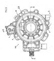
Figure 3 is a front elevational view of the differential shown inFigure 1 assembled; -
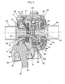
Figure 4 is a cross-sectional view of the differential shown inFigure 3 , taken generally along the lines 4-4; -
Figure 5 is a cross-sectional view of the differential shown inFigure 3 , taken generally along the lines 5-5; -
Figure 6 is an exploded perspective view of the actuator, which is also shown inFigure 1 ; and -
Figure 7 is an exploded perspective showing theball ramp system 110 andfirst cover section 28; -
Figure 8 is a front elevational view of theball ramp 31; -
Figure 9 is a wrapped cross-sectional view taken generally along the lines 9-9 ofFigure 8 ; and -
Figure 10 is a wrapped cross-sectional view showing theslot 28d in thehousing 28. - Referring to the drawings, wherein like numerals represent like parts throughout the several views, there is generally disclosed at 100 (see
Fig. 3 ) a differential. Since engaging the differential clutch (reduction in differential capability), greatly increases steering effort, it is engaged only when left and right wheel speed sensors detect a difference in rate beyond a preset value. Hysteresis is employed to prevent excessive cycling. Additionally, the clutch pack engagement is variable. At slower speeds, the torque capacity is increased. As vehicle speed increases, the torque capability is reduced, until at high enough speeds, the clutch pack does not engage. This is done to preserve proper high-speed handling while retaining low-speed tractive capability. Additionally, there may also be a feature that when the system senses a need for left/right torque capacity, the system energizes the front/rear roller clutch mechanism. This is done to prevent torque reversals in the front wheel drive from disengaging the front wheel drive and causing a cycling of automatic engagement routine during left/right clutch engagement. However, the present invention does not address the control system for doing so. The present invention is directed toward the differential 100. A suitable control system may be used. - Referring now to
Figures 1 ,2A ,2B and6 to show the components of the differential 100, shown inFig. 3 , andFigures 4 and5 to show the components in the assembled differential 100, it is seen that the differential 100 includes a housing having a first,carrier section 28, acarrier 30 and a second,cover section 29. Thecarrier section 28 andcover section 29 form an outer differential housing and define 29. Thecarrier section 28 andcover section 29 form an outer differential housing and define an inner cavity in which a majority of the components are positioned. Thecarrier section 28 has a first circular opening 28a through which apinion 32 is positioned. Thepinion 32 is assembled in the opening 28a with abearing 20,ball bearing 18, retainingring 13, beveled retainingring 14 andseal 44. Thepinion 32 has a plurality ofteeth 32a at one end. Thepinion 32 is rotated, by means well known in the art and is driven by the motor of the ATV or utility vehicle. - A
first side gear 35 has a plurality ofteeth 35a and ashaft 35b (Fig. 28). Abearing 25 is positioned on theshaft 35b and theshaft 35b extends through acentral bore 30a of thecarrier 30. Abearing 23 and hub-shim 16 are positioned on thehub 29a which defines the opening 29b of thecover section 29. Theshaft 35b extends into the opening 29b. Afirst half shaft 38 has a plurality of splines 38a and are inserted into a bore ofshaft 35b which has corresponding splines (not shown), to thereby drive thehalf shaft 38 and a wheel on one side. Asuitable retaining ring 15 andseal 45 are utilized. Positioned around the end of theshaft 35b that extends to the left, as viewed inFigure 2B , is abearing 19.Suitable plugs 4 may also be utilized. - A
second side gear 37 has a plurality of teeth 37a and ashaft 37b on which a plurality of splines 37c are formed. There are splines (not shown) internal to theshaft 37b. Theshaft 37b has abearing 24 around it and is positioned through acentral bore 33a ofring gear 33. Theshaft 37b extends into the bore 28b of thecarrier section 28. Asecond half shaft 39 has a plurality of splines 39a which mesh with splines (not shown) in the bore of theshaft 37b, wherein rotational movement of thesecond side gear 37 is transmitted to thesecond half shaft 39 and a wheel on a second side. Asuitable seal 45 and retainingring 15 may be utilized, as is well known in the art. Thering gear 33 has a plurality ofteeth 33b that, when positioned in the cavity of thecarrier section 28, meshes with theteeth 32a of thepinion gear 32. - Three sets of planet gears include three
planet gears 36a and threeplanet gears 36b. The planet gears 36a and 36b are just one example of "differential gears" that may be used. Other types of differential gears are possible. Three sets of planet gears are utilized in order to make the differential stronger, and it is understood that either fewer or more sets of planetary gears may be utilized. When assembled, the threeplanet gears 36a mesh with the teeth 37a of thesecond side gear 37 and the threeplanet gears 36b mesh with theteeth 35a of thefirst side gear 35. In each set, the planet gears 36a also mesh with theircorresponding planet gear 36b. The planet gears 36a, 36b are mounted on dowel pins 11 withbearings 22, as is well known in the art. The dowel pins 11 are seated andbosses 30b of thecarrier 30 and their other ends in suitable bosses in thecarrier section 28 as is well known in the art. Aclutch pack reaction plates 41 alternating with a plurality offriction plates 42, although it is not necessary that they completely alternate. Thefriction plates 42 have acentral bore 42a and are positioned on theshaft 37b of theside gear 37. Thefriction plates 42 have a splined inner diameter that matches with the splines 37c of theshaft 37, thereby tying the friction plates to theside gear 37. Thereaction plates 41 have a plurality ofextensions 41 a. Theextensions 41a are positioned inslots 33c, thereby tying thereaction plates 41 to thering gear 33. It is understood that thering gear 33 is the driven member, that is driven by thepinion 32. However, it is understood that other suitable constructions could also be utilized in the present invention. Thereaction plates 41 also have acentral bore 41b for mounting over theshaft 37b. A ball ramp system, generally designated at 110, includes arotating ball ramp 31 that is generally circular and is positioned in an annular cavity formed in thecarrier section 28. Threeroller balls 2 are positioned inslots 28d formed in thecarrier section 28 andslots 31c. Thus far described, such a ball ramp is well known in the art. It can be seen that theball ramp system 110 includes theball ramp 31,roller balls 2 andcarrier section 28. Positioned between theball ramp 31 and thefriction plate 42 is ashim 17, andneedle thrust bearing 21. Theball ramp 31 has an angle of 5 degrees. - The
ball ramp 31 includes an actuator arm 31a (Fig. 8 ) which has a plurality ofteeth 31b formed therein. Theteeth 31b are utilized to cause rotational movement of theball ramp 31, as well be described more fully hereafter. This movement is caused by anactuator assembly 40, an exploded view of which is shown inFigure 6 . - The
carrier 30 is secured to thecarrier section 28 byscrews 7. Thecover section 29 is secured to thecarrier section 28 byscrews 6. Afirst speed sensor 43a is secured to thecover section 29 by screw 8a (Fig. 2B ). Thefirst speed sensor 43a senses the speed of thehalf shaft 38. Asecond speed sensor 43c is secured to thecarrier section 28 byscrew 8b (Fig. 2A ) and senses the speed of thehalf shaft 39. Avent tube 34 may be utilized. Ahex flange plug 3 is used to plug theopening 28c of thecarrier section 28. A plug 1 and washer 9 (Fig.1 ,3 ) are used to plug theopening 29c. Adowel pin 12 is inserted into openings in each of thesections ball ramp 31. Ahex screw 5 holds the back of the actuator to the case for additional strength. Apin 10 extends betweencarrier section 28 andcover section 29 and is used for case alignment, as is well known in the art. - An
extension spring 27 is attached to the end of the actuator arm 31a and returns the actuator arm 31a back to a first, non-differentiating position. Screw 27a holds the other end of theextention spring 27. - Referring now to
Figure 6 , there is shown an exploded perspective view of theactuator assembly 40. Theactuator assembly 40 includes a house orcase 112 that has aDC motor 114 positioned in the cavity of thecase 112. TheDC motor 114 is a motor having an electrical power of 39 watts, at rated load such as model number RS-555VC-3267 made by Mabuchi Motor America Corp. Anactuator gear 107 is mounted on theoutput shaft 114a of theDC motor 114. Amid-actuator shaft 109 is mounted for rotation withbearings 113 between thecase 112 and a case-cover 120. On themid-actuator shaft 109 is mounted a mid-actuator gear 121 that meshes withactuator gear 107. Also mounted on themid-actuator shaft 109 is anactuator gear 108. Anactuator arm shaft 106 is rotatably mounted between thecase 112 and case-cover 120 withball bearings actuator arm shaft 106 an actuator gear 111 is mounted. O-rings actuator arm shaft 106. Theactuator gear 108 meshes with the actuator gear 111. At the one end of theactuator arm shaft 106 is a gear 106a. The gear 106a extends out of thebore 112a ofcase 112. The gear 106a meshes with theteeth 31b on themoveable ball ramp 31. Screws 101 are used to secure thecase cover 120 to thecase 112. Dowel pins 102 are positioned between thecase 112 and case cover 120 for case alignment, as is well known in the art. - Referring now to
Figure 7 , there are threeslots 28d that are formed in thecarrier section 28. Theslots 28d, as also shown inFigure 10 , are shaped similar to theslots 31c shown inFigure 9 .Figure 8 shows the front elevational view of theball ramp 31 with theteeth 31b. Threeslots 31c are formed around the perimeter of theball ramp 31 and theroller balls 2 are positioned therein. The angle "A" is shown as 5 degrees. It is up this angle that theroller balls 2 move as theball ramp 31 is rotated.Figure 10 shows thecorresponding slot 28d formed in thecarrier section 28 and also has a similar angle "B" of 5 degrees. - In the embodiment described, the mechanical power enters the differential 100 from the
pinion gear 32 to thering gear 33. With other embodiments, the power may enter the differential 100 via a chain drive or parallel axis gearing. Differential action is provided by the planet gears 3 6a, 36b coupled with side gears 35, 37, as it is well known in the art. As previously mentioned, differential action could also be provided by side gears coupled with bevel gears, as is well known in the art. Since a differential will only deliver the lesser torque that is available to the left and right wheels, loss of traction on one wheel results in loss of torque delivery to the other wheel. A clutch pack, havingreaction plates 41 andfriction plates 42, nested in thering gear 33, couples aside gear 37 with thering gear 33, with a coupling torque that is proportional to the amount of linear force applied to the clutch pack. Since a differential is a summing device ("left wheel speed" + "right wheel speed" = 2x "ring gear speed"), the coupling action will reduce or eliminate the speed differential between the two wheels during events that cause one wheel to experience a loss of traction. - To provide a coupling torque between the
ring gear 33 and theside gear 37, the clutch pack (reaction plates 41 and friction plates 42) requires an applied linear force. This is accomplished via theDC motor 114 coupled through a gear train, as previously described, to a ball ramp system, including aball ramp 31,roller balls 2 andcarrier section 28. Theball ramp 31 is separated from rotation of the friction plates andreaction plates 42 by athrust bearing 21. The high efficiency of the gear train, and the ball ramp system allows theDC motor 114 to be small and easily controlled by a low cost computerized controller (not shown), based on various input, such as input from thespeed sensors 43a, 43b. - There is a relationship between the DC motor size, gear ratios and ramp angle. The DC motor has electrical power at rated load of preferably from 40 to 175 watts and more preferably from 64 to 125 watts or a mechanical power at rated loads of from 19 to 82 watts and more preferably from 30 to 60 watts. In the example previously given, the rating is 82.38 electrical power and 38.76 mechanical power.
- The gear train, from the
DC motor 114 to theactuator assembly 40, preferably has a ratio of from 100:1 to 500:1 and more preferably from 150:1 to 350:1. The ball ramp angle, for both the ramp on theball ramp 31 andcarrier section 28 is preferably from 0.5 degrees to 15 degrees and more preferably from 2 degrees to 10 degrees. In the embodiment shown, the gear ratio is 212.8:1 and the ramp angles "A" and "B" are 5 degrees.
Claims (18)
- A differential (100) for use in an all-terrain vehicle or an utility vehicle having a motor, the differential (100) comprising:a) a differential housing having a first, carrier section (28) and a second, cover section (29);b) first and second side gears (35, 37), the first side gear (35) adapted and configured to receive a first shaft (38) for driving a first wheel and the second side gear (37) adapted and configured to receive a second shaft (39) for driving a second wheel;c) at least one set of differential gears (36a, 36b), each set comprising:i. a first differential gear (36a) positioned to engage the first side gear (35) and rotatably mounted; andii. a second differential gear (36b) positioned to engage the second side gear (37) and rotatably mounted, the first differential gear (36a) also engaging the second differential gear (36b); andd) a driven member rotatably mounted in the carrier section (28), the driven member adapted and configured to be driven by the motor;e) a clutch pack having a set of friction plates (42) and reaction plates (41);f) one of the sets of friction plates (42) and reaction plates (41) operatively connected to the driven member and the other of the sets of friction plates (42) and reaction plates (41) operatively connected to one of the first (35) and second side gears (37);g) a ball ramp (31) positioned between the carrier section (28) and the clutch pack (41, 42), andh) a DC motor (114) operatively connected to the ball ramp (31), characterized in that actuation of the DC motor (114) rotates the ball ramp (31) resulting in linear movement of the ball ramp (31) and compression of the clutch pack (41, 42) by means of a shim (17), arranged between the ball ramp (31) and the clutch pack (41, 42), thereby coupling the driven member to the one of the first (35) and second side gears (37) with a variable coupling torque to reduce or eliminate speed differential between the first shaft (38) and the second shaft (39).
- The differential of claim 1, wherein the driven member is a ring gear (33).
- The differential of claim 1, wherein the friction plates (42) alternate with the reaction plates (41).
- The differential of claim 1, wherein said DC motor (114) having an electrical power, at rated loads, of from 40 to 175 watts.
- The differential of claim 4, wherein the DC motor (114) is from 64 to 125 watts.
- The differential of claim 5, further comprising a gear train, the gear train comprising:(a) an actuator gear (107) operatively connected to and driven by the DC motor (114); and(b) a gear (106a) operatively connected to the ball ramp (31), the gear train having a gear ratio of at least 100:1 to 500:1.
- The differential of claim 6, wherein the gear ratio is from 150:1 to 350:1.
- The differential of claim 6, further comprising the ball ramp (31) having an angled surface on which a roller ball (2) moves, the angled surface having an angle of from 0.5 degrees to 15 degrees.
- The differential of claim 8, wherein the angle is from 2 degrees to 10 degrees.
- The differential as claimed in claim 1,
wherein the at least one set of differential gears (36a, 36b) comprises:(i) a first planet gear representing the first differential gear (36a) positioned to engage the first side gear (35) and rotatably mounted on dowel pins (11) operatively connected to the carrier section (28); and(ii) a second planet gear representing the second differential gear (36b) positioned to engage the second side gear (37) and rotatably mounted on dowel pins (11), the dowel pins (11) are operatively connected to the carrier section (28), the first planet gear also engaging the second planet gear. - The differential of claim 10, wherein the driven member is a ring gear (33).
- The differential of claim 10, wherein the friction plates (42) alternate with the reaction plates (41).
- The differential of claim 10, wherein said DC motor (114) having an electrical power, at rated loads, of from 40 to 175 watts.
- The differential of claim 13, wherein the DC motor (114) is from 64 to 125 watts.
- The differential of claim 10, further comprising a gear train, the gear train comprising:(a) an actuator gear (107) operatively connected to and driven by the DC motor (114); and(b) a gear (106a) operatively connected to the ball ramp, the gear train having a gear ratio of at least 100:1 to 500:1.
- The differential of claim 15, wherein the gear ratio is from 150:1 to 350:1.
- The differential of claim 10, wherein said ball ramp (31) having an angled surface on which the roller ball (2) moves, the angled surface having an angle of from 0.5 degrees to 15 degrees.
- The differential of claim 17, wherein the angle is from 2 degrees to 10 degrees.
Applications Claiming Priority (2)
| Application Number | Priority Date | Filing Date | Title |
|---|---|---|---|
| US11/251,094 US7278945B2 (en) | 2005-10-14 | 2005-10-14 | Differential |
| PCT/US2006/038039 WO2007047064A2 (en) | 2005-10-14 | 2006-09-28 | Differential |
Publications (3)
| Publication Number | Publication Date |
|---|---|
| EP1937503A2 EP1937503A2 (en) | 2008-07-02 |
| EP1937503A4 EP1937503A4 (en) | 2010-12-22 |
| EP1937503B1 true EP1937503B1 (en) | 2014-05-14 |
Family
ID=37948840
Family Applications (1)
| Application Number | Title | Priority Date | Filing Date |
|---|---|---|---|
| EP06815782.5A Active EP1937503B1 (en) | 2005-10-14 | 2006-09-28 | Differential |
Country Status (4)
| Country | Link |
|---|---|
| US (1) | US7278945B2 (en) |
| EP (1) | EP1937503B1 (en) |
| CA (1) | CA2625612C (en) |
| WO (1) | WO2007047064A2 (en) |
Families Citing this family (11)
| Publication number | Priority date | Publication date | Assignee | Title |
|---|---|---|---|---|
| US8122993B2 (en) * | 2008-06-11 | 2012-02-28 | Polaris Industries Inc. | Power steering for an all terrain vehicle |
| CN102227328B (en) * | 2008-11-07 | 2015-08-19 | 麦格纳动力系美国有限公司 | Electric drive two-speed transaxle |
| USD779561S1 (en) * | 2015-07-17 | 2017-02-21 | Eaton Corporation | Hydraulic control unit |
| US10962097B2 (en) | 2017-09-19 | 2021-03-30 | Bombardier Recreational Products Inc. | Control of a limited slip differential based on a steering angle of a vehicle |
| US10836252B2 (en) | 2017-09-19 | 2020-11-17 | Bombardier Recreational Products Inc. | Control of a limited slip differential based on an engine torque |
| US11378167B2 (en) | 2017-09-19 | 2022-07-05 | Bombardier Recreational Products Inc. | Control of a limited slip differential based on an accelerator control position |
| US11674578B2 (en) | 2017-09-19 | 2023-06-13 | Bombardier Recreational Products Inc. | Control of a limited slip differential optimized for slippery driving conditions |
| US10793181B2 (en) | 2018-02-13 | 2020-10-06 | Polaris Industries Inc. | All-terrain vehicle |
| CN114555963B (en) * | 2019-10-09 | 2025-03-07 | 美国轮轴制造公司 | Drive train components with lightweight ball ramp mechanisms |
| EP4127513A1 (en) | 2020-04-02 | 2023-02-08 | e-AAM Driveline Systems AB | Drive unit for automotive vehicle |
| US12612963B1 (en) * | 2024-12-03 | 2026-04-28 | Schaeffler Technologies AG & Co. KG | Extended differential output gear |
Family Cites Families (23)
| Publication number | Priority date | Publication date | Assignee | Title |
|---|---|---|---|---|
| US4507984A (en) | 1982-03-08 | 1985-04-02 | Eaton Corporation | Single shaft positive drive |
| US4488454A (en) | 1982-03-10 | 1984-12-18 | Eaton Corporation | Balking clamp positive drive |
| US4513633A (en) | 1982-04-08 | 1985-04-30 | Eaton Corporation | Positive drive and generated cam surfaces therefor |
| US4544869A (en) | 1983-10-05 | 1985-10-01 | Unisen, Inc. | Electronic control circuit for bi-directional motion |
| US4559846A (en) | 1983-11-10 | 1985-12-24 | Dana Corporation | System for shifting a vehicle to two or four-wheel drive |
| US4715467A (en) | 1984-03-27 | 1987-12-29 | Fuji Jukogyo Kabushiki Kaisha | Control system for a four-wheel drive vehicle |
| US4598609A (en) | 1984-04-23 | 1986-07-08 | Eaton Corporation | Positive drive |
| DE3909112A1 (en) | 1988-05-05 | 1990-09-27 | Uni Cardan Ag | GEARBOX |
| DE3915959A1 (en) * | 1989-05-18 | 1990-11-22 | Gkn Automotive Ag | GEARBOX |
| DE3920861A1 (en) * | 1989-06-07 | 1990-12-13 | Gkn Automotive Ag | GEARBOX |
| DE59003072D1 (en) * | 1989-08-21 | 1993-11-18 | Gkn Automotive Ag | Lockable differential gear. |
| EP0466863B1 (en) | 1990-02-14 | 1993-06-16 | Gkn Automotive Aktiengesellschaft | Device for switching on a drive train |
| JP2971920B2 (en) | 1990-07-18 | 1999-11-08 | 栃木富士産業株式会社 | Planetary gear differential |
| DE4217784C2 (en) * | 1991-06-12 | 1994-02-17 | Viscodrive Gmbh | Differential gear |
| US5195604A (en) | 1991-06-17 | 1993-03-23 | Warn Industries, Inc. | All wheel drive vehicle with independent wheel braking |
| JP4274508B2 (en) | 2000-03-15 | 2009-06-10 | 本田技研工業株式会社 | Two-wheel four-wheel drive switching device for vehicles |
| US6319166B1 (en) | 2000-05-15 | 2001-11-20 | Eaton Corporation | Compact locking differential |
| DE10065356C1 (en) * | 2000-12-27 | 2002-09-12 | Gkn Automotive Gmbh | Electromechanical torque control - acceleration of the return |
| US6537172B1 (en) | 2001-10-18 | 2003-03-25 | Eaton Corporation | Electronically actuated modulatable differential |
| US6604731B2 (en) | 2001-11-12 | 2003-08-12 | Warn Industries, Inc. | Utility winch |
| US6571928B1 (en) * | 2001-12-21 | 2003-06-03 | Gkn Automotive, Inc. | Engagement mechanism with two stage ramp angle |
| US6808037B1 (en) * | 2003-04-08 | 2004-10-26 | New Venture Gear, Inc. | On-demand transfer case |
| DE20314141U1 (en) * | 2003-09-10 | 2005-01-27 | Gkn Automotive Gmbh | axial setting |
-
2005
- 2005-10-14 US US11/251,094 patent/US7278945B2/en not_active Expired - Lifetime
-
2006
- 2006-09-28 CA CA002625612A patent/CA2625612C/en active Active
- 2006-09-28 EP EP06815782.5A patent/EP1937503B1/en active Active
- 2006-09-28 WO PCT/US2006/038039 patent/WO2007047064A2/en not_active Ceased
Also Published As
| Publication number | Publication date |
|---|---|
| CA2625612A1 (en) | 2007-04-26 |
| WO2007047064A2 (en) | 2007-04-26 |
| US7278945B2 (en) | 2007-10-09 |
| EP1937503A2 (en) | 2008-07-02 |
| CA2625612C (en) | 2009-01-27 |
| WO2007047064A3 (en) | 2007-08-02 |
| US20070087890A1 (en) | 2007-04-19 |
| EP1937503A4 (en) | 2010-12-22 |
Similar Documents
| Publication | Publication Date | Title |
|---|---|---|
| US5098360A (en) | Differential gear with limited slip and locking mechanism | |
| US11015689B2 (en) | Multi-speed electric machine gearbox with low drive ratio | |
| EP2059688B1 (en) | Disconnect | |
| JPH11129773A (en) | Multiple-speed transfer case | |
| JP2772979B2 (en) | Torque distribution control device for four-wheel drive vehicle | |
| US20060011441A1 (en) | Ball ramp actuator having differential drive | |
| CA2625612C (en) | Differential | |
| US5080641A (en) | Torque split control system for a four-wheel drive motor vehicle | |
| CN107020951B (en) | Splitter | |
| US9638305B2 (en) | Differential assembly for vehicles | |
| JPS63176728A (en) | Four-wheel-drive vehicle with torque distribution control device | |
| US20080308340A1 (en) | Transaxle | |
| US7029415B2 (en) | Differential apparatus | |
| CA2327235C (en) | Power transmission device for a four-wheel drive vehicle | |
| JPH0949560A (en) | Differential device | |
| JPH0361122A (en) | Four-wheel drive vehicle with center differential device | |
| US11938811B2 (en) | Multi-stage shifting actuator for a vehicle power transfer unit | |
| US11130537B1 (en) | System and method for repowering a personal transport vehicle to convert from electric motor power to internal combustion engine power | |
| US10913350B2 (en) | Ranged power take-off unit for transaxle | |
| US6254506B1 (en) | Transmission for four-wheel drive vehicle | |
| JP4246301B2 (en) | Four-wheel drive device for vehicle | |
| JP3249706U (en) | Mechanical automatic tightening differential device | |
| JP4626747B2 (en) | Torque distribution control device | |
| US5906558A (en) | Limited slip differential for a vehicle | |
| JPH0629089Y2 (en) | Shift operation mechanism for vehicle power distribution device |
Legal Events
| Date | Code | Title | Description |
|---|---|---|---|
| PUAI | Public reference made under article 153(3) epc to a published international application that has entered the european phase |
Free format text: ORIGINAL CODE: 0009012 |
|
| 17P | Request for examination filed |
Effective date: 20080514 |
|
| AK | Designated contracting states |
Kind code of ref document: A2 Designated state(s): AT BE BG CH CY CZ DE DK EE ES FI FR GB GR HU IE IS IT LI LT LU LV MC NL PL PT RO SE SI SK TR |
|
| RIN1 | Information on inventor provided before grant (corrected) |
Inventor name: MAKI, GREGORY, L. Inventor name: HAMRIN, JOHN EDWARD Inventor name: DUNLAP, JOEL Inventor name: CANN, MATTHEW DOUGLAS |
|
| A4 | Supplementary search report drawn up and despatched |
Effective date: 20101122 |
|
| RIC1 | Information provided on ipc code assigned before grant |
Ipc: B60K 23/08 20060101AFI20080418BHEP Ipc: B60K 17/346 20060101ALI20101116BHEP Ipc: F16H 48/30 20060101ALI20101116BHEP Ipc: F16H 48/22 20060101ALI20101116BHEP |
|
| 17Q | First examination report despatched |
Effective date: 20110818 |
|
| DAX | Request for extension of the european patent (deleted) | ||
| GRAP | Despatch of communication of intention to grant a patent |
Free format text: ORIGINAL CODE: EPIDOSNIGR1 |
|
| INTG | Intention to grant announced |
Effective date: 20131219 |
|
| GRAS | Grant fee paid |
Free format text: ORIGINAL CODE: EPIDOSNIGR3 |
|
| GRAA | (expected) grant |
Free format text: ORIGINAL CODE: 0009210 |
|
| AK | Designated contracting states |
Kind code of ref document: B1 Designated state(s): AT BE BG CH CY CZ DE DK EE ES FI FR GB GR HU IE IS IT LI LT LU LV MC NL PL PT RO SE SI SK TR |
|
| RAP1 | Party data changed (applicant data changed or rights of an application transferred) |
Owner name: TEAM INDUSTRIES, INC. |
|
| REG | Reference to a national code |
Ref country code: GB Ref legal event code: FG4D |
|
| REG | Reference to a national code |
Ref country code: AT Ref legal event code: REF Ref document number: 667999 Country of ref document: AT Kind code of ref document: T Effective date: 20140615 |
|
| REG | Reference to a national code |
Ref country code: IE Ref legal event code: FG4D |
|
| REG | Reference to a national code |
Ref country code: DE Ref legal event code: R096 Ref document number: 602006041607 Country of ref document: DE Effective date: 20140626 |
|
| REG | Reference to a national code |
Ref country code: AT Ref legal event code: MK05 Ref document number: 667999 Country of ref document: AT Kind code of ref document: T Effective date: 20140514 Ref country code: NL Ref legal event code: VDEP Effective date: 20140514 |
|
| REG | Reference to a national code |
Ref country code: LT Ref legal event code: MG4D |
|
| PG25 | Lapsed in a contracting state [announced via postgrant information from national office to epo] |
Ref country code: IS Free format text: LAPSE BECAUSE OF FAILURE TO SUBMIT A TRANSLATION OF THE DESCRIPTION OR TO PAY THE FEE WITHIN THE PRESCRIBED TIME-LIMIT Effective date: 20140914 Ref country code: FI Free format text: LAPSE BECAUSE OF FAILURE TO SUBMIT A TRANSLATION OF THE DESCRIPTION OR TO PAY THE FEE WITHIN THE PRESCRIBED TIME-LIMIT Effective date: 20140514 Ref country code: GR Free format text: LAPSE BECAUSE OF FAILURE TO SUBMIT A TRANSLATION OF THE DESCRIPTION OR TO PAY THE FEE WITHIN THE PRESCRIBED TIME-LIMIT Effective date: 20140815 Ref country code: LT Free format text: LAPSE BECAUSE OF FAILURE TO SUBMIT A TRANSLATION OF THE DESCRIPTION OR TO PAY THE FEE WITHIN THE PRESCRIBED TIME-LIMIT Effective date: 20140514 Ref country code: CY Free format text: LAPSE BECAUSE OF FAILURE TO SUBMIT A TRANSLATION OF THE DESCRIPTION OR TO PAY THE FEE WITHIN THE PRESCRIBED TIME-LIMIT Effective date: 20140514 |
|
| PG25 | Lapsed in a contracting state [announced via postgrant information from national office to epo] |
Ref country code: SE Free format text: LAPSE BECAUSE OF FAILURE TO SUBMIT A TRANSLATION OF THE DESCRIPTION OR TO PAY THE FEE WITHIN THE PRESCRIBED TIME-LIMIT Effective date: 20140514 Ref country code: LV Free format text: LAPSE BECAUSE OF FAILURE TO SUBMIT A TRANSLATION OF THE DESCRIPTION OR TO PAY THE FEE WITHIN THE PRESCRIBED TIME-LIMIT Effective date: 20140514 Ref country code: AT Free format text: LAPSE BECAUSE OF FAILURE TO SUBMIT A TRANSLATION OF THE DESCRIPTION OR TO PAY THE FEE WITHIN THE PRESCRIBED TIME-LIMIT Effective date: 20140514 Ref country code: ES Free format text: LAPSE BECAUSE OF FAILURE TO SUBMIT A TRANSLATION OF THE DESCRIPTION OR TO PAY THE FEE WITHIN THE PRESCRIBED TIME-LIMIT Effective date: 20140514 Ref country code: PL Free format text: LAPSE BECAUSE OF FAILURE TO SUBMIT A TRANSLATION OF THE DESCRIPTION OR TO PAY THE FEE WITHIN THE PRESCRIBED TIME-LIMIT Effective date: 20140514 |
|
| PG25 | Lapsed in a contracting state [announced via postgrant information from national office to epo] |
Ref country code: PT Free format text: LAPSE BECAUSE OF FAILURE TO SUBMIT A TRANSLATION OF THE DESCRIPTION OR TO PAY THE FEE WITHIN THE PRESCRIBED TIME-LIMIT Effective date: 20140915 |
|
| PG25 | Lapsed in a contracting state [announced via postgrant information from national office to epo] |
Ref country code: SK Free format text: LAPSE BECAUSE OF FAILURE TO SUBMIT A TRANSLATION OF THE DESCRIPTION OR TO PAY THE FEE WITHIN THE PRESCRIBED TIME-LIMIT Effective date: 20140514 Ref country code: RO Free format text: LAPSE BECAUSE OF FAILURE TO SUBMIT A TRANSLATION OF THE DESCRIPTION OR TO PAY THE FEE WITHIN THE PRESCRIBED TIME-LIMIT Effective date: 20140514 Ref country code: BE Free format text: LAPSE BECAUSE OF FAILURE TO SUBMIT A TRANSLATION OF THE DESCRIPTION OR TO PAY THE FEE WITHIN THE PRESCRIBED TIME-LIMIT Effective date: 20140514 Ref country code: DK Free format text: LAPSE BECAUSE OF FAILURE TO SUBMIT A TRANSLATION OF THE DESCRIPTION OR TO PAY THE FEE WITHIN THE PRESCRIBED TIME-LIMIT Effective date: 20140514 Ref country code: CZ Free format text: LAPSE BECAUSE OF FAILURE TO SUBMIT A TRANSLATION OF THE DESCRIPTION OR TO PAY THE FEE WITHIN THE PRESCRIBED TIME-LIMIT Effective date: 20140514 Ref country code: EE Free format text: LAPSE BECAUSE OF FAILURE TO SUBMIT A TRANSLATION OF THE DESCRIPTION OR TO PAY THE FEE WITHIN THE PRESCRIBED TIME-LIMIT Effective date: 20140514 |
|
| REG | Reference to a national code |
Ref country code: DE Ref legal event code: R097 Ref document number: 602006041607 Country of ref document: DE |
|
| PG25 | Lapsed in a contracting state [announced via postgrant information from national office to epo] |
Ref country code: NL Free format text: LAPSE BECAUSE OF FAILURE TO SUBMIT A TRANSLATION OF THE DESCRIPTION OR TO PAY THE FEE WITHIN THE PRESCRIBED TIME-LIMIT Effective date: 20140514 |
|
| PLBE | No opposition filed within time limit |
Free format text: ORIGINAL CODE: 0009261 |
|
| STAA | Information on the status of an ep patent application or granted ep patent |
Free format text: STATUS: NO OPPOSITION FILED WITHIN TIME LIMIT |
|
| 26N | No opposition filed |
Effective date: 20150217 |
|
| PG25 | Lapsed in a contracting state [announced via postgrant information from national office to epo] |
Ref country code: LU Free format text: LAPSE BECAUSE OF FAILURE TO SUBMIT A TRANSLATION OF THE DESCRIPTION OR TO PAY THE FEE WITHIN THE PRESCRIBED TIME-LIMIT Effective date: 20140928 Ref country code: MC Free format text: LAPSE BECAUSE OF FAILURE TO SUBMIT A TRANSLATION OF THE DESCRIPTION OR TO PAY THE FEE WITHIN THE PRESCRIBED TIME-LIMIT Effective date: 20140514 |
|
| REG | Reference to a national code |
Ref country code: CH Ref legal event code: PL |
|
| REG | Reference to a national code |
Ref country code: DE Ref legal event code: R097 Ref document number: 602006041607 Country of ref document: DE Effective date: 20150217 |
|
| REG | Reference to a national code |
Ref country code: IE Ref legal event code: MM4A |
|
| PG25 | Lapsed in a contracting state [announced via postgrant information from national office to epo] |
Ref country code: SI Free format text: LAPSE BECAUSE OF FAILURE TO SUBMIT A TRANSLATION OF THE DESCRIPTION OR TO PAY THE FEE WITHIN THE PRESCRIBED TIME-LIMIT Effective date: 20140514 Ref country code: LI Free format text: LAPSE BECAUSE OF NON-PAYMENT OF DUE FEES Effective date: 20140930 Ref country code: CH Free format text: LAPSE BECAUSE OF NON-PAYMENT OF DUE FEES Effective date: 20140930 |
|
| PG25 | Lapsed in a contracting state [announced via postgrant information from national office to epo] |
Ref country code: IE Free format text: LAPSE BECAUSE OF NON-PAYMENT OF DUE FEES Effective date: 20140928 |
|
| PG25 | Lapsed in a contracting state [announced via postgrant information from national office to epo] |
Ref country code: BG Free format text: LAPSE BECAUSE OF FAILURE TO SUBMIT A TRANSLATION OF THE DESCRIPTION OR TO PAY THE FEE WITHIN THE PRESCRIBED TIME-LIMIT Effective date: 20140514 |
|
| PG25 | Lapsed in a contracting state [announced via postgrant information from national office to epo] |
Ref country code: HU Free format text: LAPSE BECAUSE OF FAILURE TO SUBMIT A TRANSLATION OF THE DESCRIPTION OR TO PAY THE FEE WITHIN THE PRESCRIBED TIME-LIMIT; INVALID AB INITIO Effective date: 20060928 Ref country code: TR Free format text: LAPSE BECAUSE OF FAILURE TO SUBMIT A TRANSLATION OF THE DESCRIPTION OR TO PAY THE FEE WITHIN THE PRESCRIBED TIME-LIMIT Effective date: 20140514 |
|
| REG | Reference to a national code |
Ref country code: FR Ref legal event code: PLFP Year of fee payment: 11 |
|
| REG | Reference to a national code |
Ref country code: FR Ref legal event code: PLFP Year of fee payment: 12 |
|
| REG | Reference to a national code |
Ref country code: FR Ref legal event code: PLFP Year of fee payment: 13 |
|
| P01 | Opt-out of the competence of the unified patent court (upc) registered |
Effective date: 20230531 |
|
| PGFP | Annual fee paid to national office [announced via postgrant information from national office to epo] |
Ref country code: GB Payment date: 20240923 Year of fee payment: 19 |
|
| PGFP | Annual fee paid to national office [announced via postgrant information from national office to epo] |
Ref country code: FR Payment date: 20240924 Year of fee payment: 19 |
|
| PGFP | Annual fee paid to national office [announced via postgrant information from national office to epo] |
Ref country code: DE Payment date: 20241009 Year of fee payment: 19 |
|
| PGFP | Annual fee paid to national office [announced via postgrant information from national office to epo] |
Ref country code: IT Payment date: 20240930 Year of fee payment: 19 |