EP1936730A1 - Bipolar battery stack with superimposed separators and method of manufacturing the same - Google Patents
Bipolar battery stack with superimposed separators and method of manufacturing the same Download PDFInfo
- Publication number
- EP1936730A1 EP1936730A1 EP07121749A EP07121749A EP1936730A1 EP 1936730 A1 EP1936730 A1 EP 1936730A1 EP 07121749 A EP07121749 A EP 07121749A EP 07121749 A EP07121749 A EP 07121749A EP 1936730 A1 EP1936730 A1 EP 1936730A1
- Authority
- EP
- European Patent Office
- Prior art keywords
- separators
- cathode
- anode
- electrolyte
- pair
- Prior art date
- Legal status (The legal status is an assumption and is not a legal conclusion. Google has not performed a legal analysis and makes no representation as to the accuracy of the status listed.)
- Granted
Links
- 238000004519 manufacturing process Methods 0.000 title claims abstract description 11
- 239000003792 electrolyte Substances 0.000 claims abstract description 119
- 238000000034 method Methods 0.000 claims abstract description 99
- 230000035699 permeability Effects 0.000 claims abstract description 15
- 239000003566 sealing material Substances 0.000 claims description 75
- 238000003825 pressing Methods 0.000 claims description 40
- 229920000642 polymer Polymers 0.000 claims description 25
- 239000000463 material Substances 0.000 claims description 23
- 239000011245 gel electrolyte Substances 0.000 claims description 13
- 239000008151 electrolyte solution Substances 0.000 claims description 11
- 239000012528 membrane Substances 0.000 claims description 6
- 230000015572 biosynthetic process Effects 0.000 claims description 2
- 230000008569 process Effects 0.000 description 77
- 239000010410 layer Substances 0.000 description 68
- 238000007789 sealing Methods 0.000 description 29
- 238000010586 diagram Methods 0.000 description 22
- 238000010438 heat treatment Methods 0.000 description 19
- 150000002500 ions Chemical class 0.000 description 8
- RUOJZAUFBMNUDX-UHFFFAOYSA-N propylene carbonate Chemical compound CC1COC(=O)O1 RUOJZAUFBMNUDX-UHFFFAOYSA-N 0.000 description 8
- 239000002904 solvent Substances 0.000 description 8
- KMTRUDSVKNLOMY-UHFFFAOYSA-N Ethylene carbonate Chemical compound O=C1OCCO1 KMTRUDSVKNLOMY-UHFFFAOYSA-N 0.000 description 7
- 239000004743 Polypropylene Substances 0.000 description 7
- 229910003002 lithium salt Inorganic materials 0.000 description 7
- 159000000002 lithium salts Chemical class 0.000 description 7
- 230000007246 mechanism Effects 0.000 description 7
- PXHVJJICTQNCMI-UHFFFAOYSA-N Nickel Chemical compound [Ni] PXHVJJICTQNCMI-UHFFFAOYSA-N 0.000 description 6
- 239000004698 Polyethylene Substances 0.000 description 6
- 239000006183 anode active material Substances 0.000 description 6
- 239000006256 anode slurry Substances 0.000 description 6
- 230000006870 function Effects 0.000 description 6
- HCDGVLDPFQMKDK-UHFFFAOYSA-N hexafluoropropylene Chemical group FC(F)=C(F)C(F)(F)F HCDGVLDPFQMKDK-UHFFFAOYSA-N 0.000 description 6
- 239000007788 liquid Substances 0.000 description 6
- -1 polypropylene Polymers 0.000 description 6
- 229910001290 LiPF6 Inorganic materials 0.000 description 5
- SECXISVLQFMRJM-UHFFFAOYSA-N N-Methylpyrrolidone Chemical group CN1CCCC1=O SECXISVLQFMRJM-UHFFFAOYSA-N 0.000 description 5
- 239000002033 PVDF binder Substances 0.000 description 5
- 229910052782 aluminium Inorganic materials 0.000 description 5
- XAGFODPZIPBFFR-UHFFFAOYSA-N aluminium Chemical compound [Al] XAGFODPZIPBFFR-UHFFFAOYSA-N 0.000 description 5
- 239000011230 binding agent Substances 0.000 description 5
- 239000006257 cathode slurry Substances 0.000 description 5
- 239000002131 composite material Substances 0.000 description 5
- IEJIGPNLZYLLBP-UHFFFAOYSA-N dimethyl carbonate Chemical compound COC(=O)OC IEJIGPNLZYLLBP-UHFFFAOYSA-N 0.000 description 5
- 239000003960 organic solvent Substances 0.000 description 5
- OKTJSMMVPCPJKN-UHFFFAOYSA-N Carbon Chemical compound [C] OKTJSMMVPCPJKN-UHFFFAOYSA-N 0.000 description 4
- CURLTUGMZLYLDI-UHFFFAOYSA-N Carbon dioxide Chemical compound O=C=O CURLTUGMZLYLDI-UHFFFAOYSA-N 0.000 description 4
- BVKZGUZCCUSVTD-UHFFFAOYSA-L Carbonate Chemical compound [O-]C([O-])=O BVKZGUZCCUSVTD-UHFFFAOYSA-L 0.000 description 4
- RTZKZFJDLAIYFH-UHFFFAOYSA-N Diethyl ether Chemical compound CCOCC RTZKZFJDLAIYFH-UHFFFAOYSA-N 0.000 description 4
- 125000000129 anionic group Chemical group 0.000 description 4
- 239000006182 cathode active material Substances 0.000 description 4
- 229920001577 copolymer Polymers 0.000 description 4
- 229920001155 polypropylene Polymers 0.000 description 4
- 229920002981 polyvinylidene fluoride Polymers 0.000 description 4
- RYGMFSIKBFXOCR-UHFFFAOYSA-N Copper Chemical compound [Cu] RYGMFSIKBFXOCR-UHFFFAOYSA-N 0.000 description 3
- WYURNTSHIVDZCO-UHFFFAOYSA-N Tetrahydrofuran Chemical compound C1CCOC1 WYURNTSHIVDZCO-UHFFFAOYSA-N 0.000 description 3
- 239000012752 auxiliary agent Substances 0.000 description 3
- 229910052802 copper Inorganic materials 0.000 description 3
- 239000010949 copper Substances 0.000 description 3
- 239000011888 foil Substances 0.000 description 3
- 229910052759 nickel Inorganic materials 0.000 description 3
- 230000000149 penetrating effect Effects 0.000 description 3
- 230000035515 penetration Effects 0.000 description 3
- 150000003839 salts Chemical class 0.000 description 3
- 238000003466 welding Methods 0.000 description 3
- 229910000552 LiCF3SO3 Inorganic materials 0.000 description 2
- HBBGRARXTFLTSG-UHFFFAOYSA-N Lithium ion Chemical compound [Li+] HBBGRARXTFLTSG-UHFFFAOYSA-N 0.000 description 2
- 229910002097 Lithium manganese(III,IV) oxide Inorganic materials 0.000 description 2
- 229920003171 Poly (ethylene oxide) Polymers 0.000 description 2
- 229910045601 alloy Inorganic materials 0.000 description 2
- 239000000956 alloy Substances 0.000 description 2
- 238000000429 assembly Methods 0.000 description 2
- 230000009286 beneficial effect Effects 0.000 description 2
- 229910002092 carbon dioxide Inorganic materials 0.000 description 2
- 239000001569 carbon dioxide Substances 0.000 description 2
- 239000003575 carbonaceous material Substances 0.000 description 2
- 230000006866 deterioration Effects 0.000 description 2
- 239000003822 epoxy resin Substances 0.000 description 2
- 230000004927 fusion Effects 0.000 description 2
- 229910002804 graphite Inorganic materials 0.000 description 2
- 239000010439 graphite Substances 0.000 description 2
- 229910021385 hard carbon Inorganic materials 0.000 description 2
- 239000012212 insulator Substances 0.000 description 2
- 239000005001 laminate film Substances 0.000 description 2
- 229910001416 lithium ion Inorganic materials 0.000 description 2
- 229910052751 metal Inorganic materials 0.000 description 2
- 239000002184 metal Substances 0.000 description 2
- 150000002739 metals Chemical class 0.000 description 2
- 238000012986 modification Methods 0.000 description 2
- 230000004048 modification Effects 0.000 description 2
- 239000004745 nonwoven fabric Substances 0.000 description 2
- 230000002093 peripheral effect Effects 0.000 description 2
- 229920003229 poly(methyl methacrylate) Polymers 0.000 description 2
- 229920005569 poly(vinylidene fluoride-co-hexafluoropropylene) Polymers 0.000 description 2
- 229920000647 polyepoxide Polymers 0.000 description 2
- 239000004926 polymethyl methacrylate Substances 0.000 description 2
- 229920001451 polypropylene glycol Polymers 0.000 description 2
- 229920005989 resin Polymers 0.000 description 2
- 239000011347 resin Substances 0.000 description 2
- 230000000717 retained effect Effects 0.000 description 2
- 239000002356 single layer Substances 0.000 description 2
- 239000010935 stainless steel Substances 0.000 description 2
- 229910001220 stainless steel Inorganic materials 0.000 description 2
- 229920001169 thermoplastic Polymers 0.000 description 2
- 229920005992 thermoplastic resin Polymers 0.000 description 2
- 229920001187 thermosetting polymer Polymers 0.000 description 2
- 239000004416 thermosoftening plastic Substances 0.000 description 2
- 238000009489 vacuum treatment Methods 0.000 description 2
- 230000003245 working effect Effects 0.000 description 2
- QTBSBXVTEAMEQO-UHFFFAOYSA-M Acetate Chemical compound CC([O-])=O QTBSBXVTEAMEQO-UHFFFAOYSA-M 0.000 description 1
- 241000531908 Aramides Species 0.000 description 1
- 229920000742 Cotton Polymers 0.000 description 1
- WHXSMMKQMYFTQS-UHFFFAOYSA-N Lithium Chemical compound [Li] WHXSMMKQMYFTQS-UHFFFAOYSA-N 0.000 description 1
- 239000004677 Nylon Substances 0.000 description 1
- 239000004952 Polyamide Substances 0.000 description 1
- 239000004642 Polyimide Substances 0.000 description 1
- 229920000297 Rayon Polymers 0.000 description 1
- RTAQQCXQSZGOHL-UHFFFAOYSA-N Titanium Chemical compound [Ti] RTAQQCXQSZGOHL-UHFFFAOYSA-N 0.000 description 1
- 239000006230 acetylene black Substances 0.000 description 1
- 230000001070 adhesive effect Effects 0.000 description 1
- 229920003235 aromatic polyamide Polymers 0.000 description 1
- 230000000712 assembly Effects 0.000 description 1
- 239000012298 atmosphere Substances 0.000 description 1
- 229910052799 carbon Inorganic materials 0.000 description 1
- 239000006229 carbon black Substances 0.000 description 1
- 239000011248 coating agent Substances 0.000 description 1
- 238000000576 coating method Methods 0.000 description 1
- 230000002542 deteriorative effect Effects 0.000 description 1
- 238000007599 discharging Methods 0.000 description 1
- 230000000694 effects Effects 0.000 description 1
- 238000005516 engineering process Methods 0.000 description 1
- 230000007613 environmental effect Effects 0.000 description 1
- 229910052744 lithium Inorganic materials 0.000 description 1
- 238000012544 monitoring process Methods 0.000 description 1
- 229920001778 nylon Polymers 0.000 description 1
- 239000012466 permeate Substances 0.000 description 1
- 238000007747 plating Methods 0.000 description 1
- 229920002647 polyamide Polymers 0.000 description 1
- 229920000728 polyester Polymers 0.000 description 1
- 229920000573 polyethylene Polymers 0.000 description 1
- 229920013716 polyethylene resin Polymers 0.000 description 1
- 229920001721 polyimide Polymers 0.000 description 1
- 239000005518 polymer electrolyte Substances 0.000 description 1
- 229920000098 polyolefin Polymers 0.000 description 1
- 239000002964 rayon Substances 0.000 description 1
- 230000003014 reinforcing effect Effects 0.000 description 1
- 239000007787 solid Substances 0.000 description 1
- 230000007480 spreading Effects 0.000 description 1
- 238000003892 spreading Methods 0.000 description 1
- 239000004094 surface-active agent Substances 0.000 description 1
- YLQBMQCUIZJEEH-UHFFFAOYSA-N tetrahydrofuran Natural products C=1C=COC=1 YLQBMQCUIZJEEH-UHFFFAOYSA-N 0.000 description 1
Images


Classifications
-
- H—ELECTRICITY
- H01—ELECTRIC ELEMENTS
- H01M—PROCESSES OR MEANS, e.g. BATTERIES, FOR THE DIRECT CONVERSION OF CHEMICAL ENERGY INTO ELECTRICAL ENERGY
- H01M10/00—Secondary cells; Manufacture thereof
- H01M10/04—Construction or manufacture in general
- H01M10/0413—Large-sized flat cells or batteries for motive or stationary systems with plate-like electrodes
- H01M10/0418—Large-sized flat cells or batteries for motive or stationary systems with plate-like electrodes with bipolar electrodes
-
- H—ELECTRICITY
- H01—ELECTRIC ELEMENTS
- H01M—PROCESSES OR MEANS, e.g. BATTERIES, FOR THE DIRECT CONVERSION OF CHEMICAL ENERGY INTO ELECTRICAL ENERGY
- H01M10/00—Secondary cells; Manufacture thereof
- H01M10/05—Accumulators with non-aqueous electrolyte
- H01M10/052—Li-accumulators
-
- H—ELECTRICITY
- H01—ELECTRIC ELEMENTS
- H01M—PROCESSES OR MEANS, e.g. BATTERIES, FOR THE DIRECT CONVERSION OF CHEMICAL ENERGY INTO ELECTRICAL ENERGY
- H01M10/00—Secondary cells; Manufacture thereof
- H01M10/05—Accumulators with non-aqueous electrolyte
- H01M10/058—Construction or manufacture
- H01M10/0585—Construction or manufacture of accumulators having only flat construction elements, i.e. flat positive electrodes, flat negative electrodes and flat separators
-
- H—ELECTRICITY
- H01—ELECTRIC ELEMENTS
- H01M—PROCESSES OR MEANS, e.g. BATTERIES, FOR THE DIRECT CONVERSION OF CHEMICAL ENERGY INTO ELECTRICAL ENERGY
- H01M50/00—Constructional details or processes of manufacture of the non-active parts of electrochemical cells other than fuel cells, e.g. hybrid cells
- H01M50/40—Separators; Membranes; Diaphragms; Spacing elements inside cells
- H01M50/409—Separators, membranes or diaphragms characterised by the material
- H01M50/411—Organic material
- H01M50/414—Synthetic resins, e.g. thermoplastics or thermosetting resins
-
- Y—GENERAL TAGGING OF NEW TECHNOLOGICAL DEVELOPMENTS; GENERAL TAGGING OF CROSS-SECTIONAL TECHNOLOGIES SPANNING OVER SEVERAL SECTIONS OF THE IPC; TECHNICAL SUBJECTS COVERED BY FORMER USPC CROSS-REFERENCE ART COLLECTIONS [XRACs] AND DIGESTS
- Y02—TECHNOLOGIES OR APPLICATIONS FOR MITIGATION OR ADAPTATION AGAINST CLIMATE CHANGE
- Y02E—REDUCTION OF GREENHOUSE GAS [GHG] EMISSIONS, RELATED TO ENERGY GENERATION, TRANSMISSION OR DISTRIBUTION
- Y02E60/00—Enabling technologies; Technologies with a potential or indirect contribution to GHG emissions mitigation
- Y02E60/10—Energy storage using batteries
-
- Y—GENERAL TAGGING OF NEW TECHNOLOGICAL DEVELOPMENTS; GENERAL TAGGING OF CROSS-SECTIONAL TECHNOLOGIES SPANNING OVER SEVERAL SECTIONS OF THE IPC; TECHNICAL SUBJECTS COVERED BY FORMER USPC CROSS-REFERENCE ART COLLECTIONS [XRACs] AND DIGESTS
- Y02—TECHNOLOGIES OR APPLICATIONS FOR MITIGATION OR ADAPTATION AGAINST CLIMATE CHANGE
- Y02P—CLIMATE CHANGE MITIGATION TECHNOLOGIES IN THE PRODUCTION OR PROCESSING OF GOODS
- Y02P70/00—Climate change mitigation technologies in the production process for final industrial or consumer products
- Y02P70/50—Manufacturing or production processes characterised by the final manufactured product
-
- Y—GENERAL TAGGING OF NEW TECHNOLOGICAL DEVELOPMENTS; GENERAL TAGGING OF CROSS-SECTIONAL TECHNOLOGIES SPANNING OVER SEVERAL SECTIONS OF THE IPC; TECHNICAL SUBJECTS COVERED BY FORMER USPC CROSS-REFERENCE ART COLLECTIONS [XRACs] AND DIGESTS
- Y02—TECHNOLOGIES OR APPLICATIONS FOR MITIGATION OR ADAPTATION AGAINST CLIMATE CHANGE
- Y02T—CLIMATE CHANGE MITIGATION TECHNOLOGIES RELATED TO TRANSPORTATION
- Y02T10/00—Road transport of goods or passengers
- Y02T10/60—Other road transportation technologies with climate change mitigation effect
- Y02T10/70—Energy storage systems for electromobility, e.g. batteries
-
- Y—GENERAL TAGGING OF NEW TECHNOLOGICAL DEVELOPMENTS; GENERAL TAGGING OF CROSS-SECTIONAL TECHNOLOGIES SPANNING OVER SEVERAL SECTIONS OF THE IPC; TECHNICAL SUBJECTS COVERED BY FORMER USPC CROSS-REFERENCE ART COLLECTIONS [XRACs] AND DIGESTS
- Y10—TECHNICAL SUBJECTS COVERED BY FORMER USPC
- Y10T—TECHNICAL SUBJECTS COVERED BY FORMER US CLASSIFICATION
- Y10T29/00—Metal working
- Y10T29/49—Method of mechanical manufacture
- Y10T29/49002—Electrical device making
- Y10T29/49108—Electric battery cell making
Definitions
- the invention relates generally to a bipolar battery and a method of manufacturing a bipolar battery. Aspects of the invention relate to a battery, to a battery assembly, to a method and to a vehicle.
- Japanese Laid-Open Patent Publication No. (Hei.) 11-204136 discloses a bipolar battery manufactured by preparing an electrolyte layer in a bipolar electrode wherein a cathode is formed at one side of a collector and an anode is formed at another side of the collector and by stacking the electrolyte layers to form a stack.
- the cathode and the anode are provided with the electrolyte, while the separator is overlapped with either the cathode or the anode so as to form a single layer.
- the electrolyte layer having a cathode and an anode a layer of separator into which the electrolyte penetrates and segments a cathode and an anode, or a layer of electrolyte between the cathode or anode and the separator
- the electrolyte layers are then stacked upon one another.
- a corrugation is formed on the separator to thereby form a micro gap in the electrolyte layer.
- the bubble is introduced into the electrolyte layer due to overlapping. If the stack is formed with the remained bubble, then it becomes difficult to exhaust the bubble since the cathode and the anode exist at both surfaces of the separator via the electrolyte. Further, when the bubble remains in the stack as described above, a dead space is generated wherein an ion cannot permeate, and an electron cannot move. The dead space may become a main factor for the deterioration of power. This can be a problem when trying to improve the power density.
- Embodiments of the invention may provide a bipolar battery that has a superior battery performance by improving the power density by limiting the presence of bubbles therein.
- a bipolar battery comprising at least two bipolar electrodes arranged in a stack, each of the electrodes including a cathode formed on one side of a collector and an anode formed on an opposed side of the collector and a pair of separators arranged on opposed sides of each of the electrodes in the stack, each of the pair of separators having a permeability sufficient for an electrolyte to penetrate therein; and wherein separators of adjacent ones of the electrodes are in contact with each other.
- the pair of separators is a porous membrane segmenting a cathode of a first bipolar electrode and an anode of a second, adjacent bipolar electrode
- the bipolar battery further comprising an electrolyte between the cathode of the first bipolar electrode and an adjacent separator and between the anode of a second, adjacent bipolar electrode and an adjacent other separator.
- the battery may comprise an electrolyte layer arranged at cathode and anode sides of each of the bipolar electrodes; and wherein the separators of adjacent ones of the electrodes are overlapping.
- the electrolyte layer is a polymer gel electrolyte or an electrolytic solution
- the bipolar battery further comprising a charging portion including a charging material arranged in a space between each collector and an adjacent separator and surrounding ends of an associated cathode and anode.
- the charging portion has a gap portion occluded during formation of the stack.
- the electrolyte layer is the polymer gel electrolyte; and wherein a thickness of the charging portion is less than a thickness between an adjacent cathode or anode and the polymer gel electrolyte.
- the battery may comprise an electrolyte layer arranged between each anode and between each cathode and an adjacent separator and in contact with the adjacent separator, the electrolyte layer comprising the electrolyte.
- the battery may comprise a first sealing material arranged between the cathode of each of the electrodes and a first, adjacent one of the pair of separators, the first sealing material enclosing ends of the cathode and its respective electrolyte layer and a second sealing material arranged between the anode of each of the electrodes and a second, adjacent one of the pair of separators, the second sealing material enclosing ends of the anode and its respective electrolyte layer.
- the battery may comprise a sealing material arranged between a first separator of each pair of separators and a second separator of each pair of separators, the sealing material enclosing the anode, cathode, collector and electrolyte layers of a respective bipolar electrode.
- the battery comprises a first sealing material arranged between the cathode of each of the electrodes and a first, adjacent one of the pair of separators, the first sealing material enclosing ends of the cathode and a second sealing material arranged between the anode of each of the electrodes and a second, adjacent one of the pair of separators, the second sealing material enclosing ends of the anode.
- a method of manufacturing a bipolar battery comprising forming a first bipolar electrode including a first cathode formed on one side of a first collector and a first anode formed on an opposed side of the first collector, arranging a first pair of separators on opposed sides the first bipolar electrode, each of the first pair of separators having a permeability sufficient for an electrolyte to penetrate therein, forming a second bipolar electrode including a second cathode formed on one side of a second collector and a second anode formed on an opposed side of the second collector, arranging a second pair of separators on opposed sides the second bipolar electrode, each of the second pair of separators having a permeability sufficient for the electrolyte to penetrate therein and stacking the first bipolar electrode and the second bipolar electrode such that a first separator of the first pair of separators and a second separator of the second pair of separators are in contact with each other
- the method may comprise forming an electrolyte layer including the electrolyte adjacent each of the first pair of separators and the second pair of separators and interposed at cathode and anode sides of each of the first and the second bipolar electrodes, the electrolyte layer comprising the electrode; and wherein stacking the first bipolar electrode and the second bipolar electrode further includes overlapping the first separator and the second separator with each other.
- each of the separators is a porous membrane, the method further comprising forming an electrolyte layer including the electrolyte between the first separator and the second separator, the first separator and the second separator being overlapped after stacking.
- the method may comprise forming a respective electrolyte layer including the electrolyte between the first cathode and a first, adjacent separator of the first pair of separators and between the first anode and a second, adjacent separator of the first pair of separators and forming a respective electrolyte layer including the electrolyte between the second cathode and a first, adjacent separator of the second pair of separators and between the second anode and a second, adjacent separator of the second pair of separators.
- the electrolyte of each of the electrolyte layers is a polymer gel electrolyte or an electrolytic solution, the method further comprising prior to stacking, arranging a sealing material for forming a charging portion and arranging a charging material in a space between the first collector and each of the first pair of separators to surround edges of the first cathode and the first anode.
- a gap portion is formed at the charging portion, the method further comprising exhausting a bubble remaining in an inner space of the first electrode formed by the collector, at least one of the first pair of separators and the charging material via the gap portion.
- the method may comprise occluding a gap of the gap portion by pressing the charging portion along a stacking direction of the stack after exhausting the bubble.
- the electrolyte is the polymer gel electrolyte, and a thickness of the charging portion is less than a thickness between the first cathode or first anode and the polymer gel electrolyte.
- a bipolar battery taught herein may comprise at least two bipolar electrodes arranged in a stack, each of the electrodes including a cathode formed on one side of a collector and an anode formed on an opposed side of the collector, and a pair of separators arranged on opposed sides of each of the electrodes in the stack, each of the pair of separators having a permeability sufficient for an electrolyte to penetrate therein. Separators of adjacent ones of the electrodes are in contact with each other.
- a method comprises forming a first bipolar electrode including a first cathode formed on one side of a first collector and a first anode formed on an opposed side of the first collector, arranging a first pair of separators on opposed sides the first bipolar electrode, each of the first pair of separators having a permeability sufficient for an electrolyte to penetrate therein, forming a second bipolar electrode including a second cathode formed on one side of a second collector and a second anode formed on an opposed side of the second collector, arranging a second pair of separators on opposed sides the second bipolar electrode, each of the second pair of separators having a permeability sufficient for the electrolyte to penetrate therein, and stacking the first bipolar electrode and the second bipolar electrode such that a first separator of the first pair of separators and a second separator of the second pair of separators are in contact with each other.
- FIG. 1 is a cross-sectional view of a bipolar battery constructed in accordance with a first embodiment of the invention.
- FIG. 2 is a cross-sectional view of the bipolar battery shown in FIG. 1 .
- FIG. 3 is a perspective view of a battery assembly configured to use the bipolar battery shown in FIG. 1 .
- FIG. 4 is a diagram of a vehicle wherein the battery assembly shown in FIG. 2 is mounted.
- a stack 100 is formed by preparing an electrolyte layer 120 in a bipolar electrode and stacking the electrolyte layers upon one another.
- the bipolar electrode has an anode 112, a cathode 113 and a collector 111.
- the cathode 113 is arranged at one side surface of the collector 111, and the anode 112 is arranged at another side surface of the collector 111. That is, the collector 111 is placed between the cathode 113 and the anode 112.
- the electrolyte layer 120 has a layer comprising separators 121 and 122, which are stacked upon one another (two sheets), and a layer of electrolyte between the separators 121 and 122 and the cathode 113 or the anode 112.
- the separators 121 and 122 are porous membranes having permeability for segmenting the cathode 113 or the anode 112, wherein the electrolyte can penetrate into such membranes.
- the electrolyte can be, for example, a polymer gel electrolyte (gel polymer-based electrolyte).
- separators 121 and 122 are stacked upon one another in the electrolyte layer 120, although a bubble remains in the electrolyte at the cathode or anode side of the bipolar electrode, it is easy to exhaust such a bubble via the separators 121 and 122.
- the separators 121 and 122 have permeability such that the electrolyte can penetrate therein from an opposite side surface of the cathode 113 or anode 112. Further, it is also easy to exhaust the bubble from a space between the separators 121 and 122.
- the cathode or anode side exists at one side surface of the separators 121 and 122 in the electrolyte layer 120 of the stack 100, while the separators 121 and 122 exist at another side surface. Accordingly, it is easy to exhaust the remaining bubble from one side surface to another side surface of the separators 121 and 122. It is further easy to exhaust the remaining bubble from a space between the separators 121 and 122.
- the bipolar battery 10 also has first and second sealing layers 115 and 117.
- the first sealing layer 115 is arranged at one side surface of the collector 111 and extended to surround an end of the cathode 113.
- the electrolyte layer 120 is arranged to cover the cathode 113 and the first sealing layer 115.
- the second sealing layer 117 is position-adjusted with the first sealing layer 115, thereby being arranged at another side surface of the collector 111 and extended to surround an end of the anode 112.
- a region wherein the first and second sealing layers 115 and 117 are arranged is referred to as a charging portion.
- the collector 111 is, for example, a stainless steel foil.
- the collector 111 is certainly not limited thereto and may include an aluminum foil, a clad material of nickel and aluminum, a clad material of copper and aluminum, or a plating material of a combination of the these metals.
- An anode active material of the anode 112 is, for example, a hard carbon (a non-graphitized carbon material).
- the anode active material is certainly not limited thereto since it may include a graphite-based carbon material or a lithium-transition metallic composite oxide.
- the anode active material composed of carbon and the lithium-transition metallic composite oxide is advantageous in terms of capacity and power.
- a cathode active material of the cathode 113 is, for example, LiMn 2 O 4 , although it is certainly not limited thereto.
- the lithium-transition metallic composite oxide is desirable in terms of capacity and power.
- Thicknesses of the cathode 113 and anode 112 may be set depending on the purpose of use (e.g., emphasis on power or energy) or ion conductivity.
- a charging material constituting the first and second sealing layers 115 and 117 is, for example, one-liquid uncured epoxy resin.
- the charging material is not limited thereto and may include other thermosetting resins (polypropylene or polyethylene) or thermoplastic resins. In certain embodiments, it is beneficial to select a material having a desired sealing effect depending on the type of application.
- a material for each separator 121, 122 in this embodiment can be porous PE (polyethylene) having permeability such that the electrolyte can penetrate into the separator.
- the material may include other polyolefins such as PP (polypropylene), a stack in a three-layer structure of PP/PE/PP, polyamide, polyimide, aramide or non-woven fabric.
- the non-woven fabric includes, for example, cotton, rayon, acetate, nylon or polyester.
- a host polymer of the electrolyte is, for example, PVDF-HFP (copolymer of polyvinylidene fluoride and hexafluoropropylene) containing 10% of HFP (hexafluoropropylene) copolymer.
- the host polymer is not limited thereto and may include other polymers without lithium ion conductivity or polymer (solid polymer electrolyte) with ion conductivity.
- Other polymers without lithium ion conductivity for example, include PAN (polyacrylonitile) and PMMA (polymethylmethacrylate).
- a polymer with ion conductivity for example, is PEO (polyethylene oxide) or PPO (polypropylene oxide).
- An electrolytic solution retained in the host polymer includes, for example, an organic solvent composed of PC (propylene carbonate) and EC (ethylene carbonate), and lithium salt (LiPF 6 ) as a support salt.
- the organic solvent is not limited to PC and EC since it may include other ring-type carbonate classes, chain-type carbonate classes such as dimethylcarbonate and ether classes such as tetrahydrofuran.
- the lithium salt can alternatively include other inorganic anionic salts and organic anionic salts such as LiCF 3 SO 3 instead of LiPF 6 .
- the bipolar battery 10 is housed within an exterior case 104 in the form of a stack 100 of a unit bipolar battery, thereby preventing an impact from the outside or environmental deterioration.
- Terminal leads 101 and 102 composed of a high conductive member are connected to respective collectors 111 placed at the outermost layer of the stack 100.
- the high conductive member includes, for example, aluminum, copper, titan, nickel, stainless or alloys thereof.
- the reference number 103 indicates a reinforcing plate.
- the terminal leads 101 and 102 extend to an outer portion of the exterior case 104, and each serves as an electrode tab for extracting the current from the stack 100. Further, by arranging an electrode tab of an independent separate member and connecting to the terminal leads 101 and 102 directly or by using a lead, it is possible to extract the current from the stack 100.
- the exterior case 104 can be composed of a sheet material such as polymer-metallic composite laminate film wherein metals such as aluminum, stainless, nickel or copper (including alloys thereof) are coated by an insulator such as a polypropylene film. Further, the exterior case 104 is formed by bonding a part or the entire outer periphery of the case via thermal fusion.
- the bipolar battery 10 is possible to use independently.
- the bipolar battery 10 in the form of a battery assembly 130 as shown in FIG. 3 .
- the battery assembly 130 is constituted by serializing and/or parallelizing the bipolar battery 10 and multi-connecting the bipolar batteries 10.
- the battery assembly 130 has conductive bars 132 and 134.
- the conductive bars 132 and 134 are connected to the terminal leads 101 and 102 extended from an inner portion of the bipolar battery 10.
- a connecting method includes, for example, an ultrasonic welding operation, a thermal welding operation, a laser welding operation, a rivet operation, a caulking operation or an electronic beam.
- the battery assembly module 136 By serializing and/or parallelizing and multi-connecting the battery assemblies 130, it is possible to provide a battery assembly module (a large scale battery assembly) 136 as shown in FIG. 4 . Since the battery assembly module 136 can secure a higher power, it is possible, for example, to be mounted as a power source for driving a motor of a vehicle 138.
- the vehicle includes, for example, an electric vehicle, a hybrid electric vehicle or an electric train.
- the battery assembly module 136 can perform very elaborate control such as performing a control of charging in every interior bipolar battery 10 or every battery assembly 130. Accordingly, it is possible to achieve functional improvements such as an extension of driving distance per charging at one time or an extension of lifetime of a battery mounted on a vehicle.
- FIG. 5 is a flow diagram of a method for manufacturing a bipolar battery in accordance with the first embodiment.
- the method includes a step of forming an assembly unit as a sub-assembly unit wherein the electrolyte and the separator are sequentially arranged at both sides of the bipolar electrode, a step of forming a bonded body as an assembly step for forming the stack (bonded body) wherein the assembly units (sub-assembly units) are stacked and integrated and a step of assembling for housing the integrated stack within the exterior case.
- Forming the bonded body comprises a stacking step for stacking the bipolar batteries upon one another by interposing the electrolyte layer, as will be explained below.
- the stacking step since the separators are overlapped with each other wherein the electrolytes can penetrate, it becomes easy to exhaust such a bubble left at the cathode or anode side of the bipolar electrode from a surface opposite to the cathode or anode side via the separator, which has a property for the electrolytes to penetrate therein. Further, it is also easy to exhaust the bubble from a space between the separators.
- FIG. 6 is a flow diagram of the process for forming the assembly unit shown in FIG. 5 .
- FIG. 7 is a plan view of the process for forming the electrode shown in FIG. 6
- FIG. 8 is a cross-sectional view of the process for forming the electrode shown in FIG. 6 .
- FIG. 9 is a cross-sectional view of the process for arranging the electrolyte shown in FIG. 6
- FIG. 10 is a plan view of the process for arranging the sealing material shown in FIG. 6 .
- FIG. 11 is a cross-sectional view of the process for arranging the sealing material shown in FIG. 6 .
- FIG. 12A is a cross-sectional view of the process for arranging the separator shown in FIG. 6 and the assembly unit 108 as a sub-assembly.
- the process of forming an assembly unit can include the steps of forming the electrode, arranging the electrolyte, arranging the sealing material and arranging the separator.
- cathode slurry is first adjusted in the process of forming the electrode.
- the cathode slurry is prepared, for example, to have a cathode active material of 85 wt%, a conductive auxiliary agent of 5 wt% and a binder of 10 wt%.
- the cathode slurry obtains a desired viscosity by adding a viscosity adjusting solvent therein.
- the cathode active material is, for example, LiMn 2 O 4
- the conductive auxiliary agent is acetylene black.
- the binder is PVDF (polyvinylidene fluoride).
- the viscosity adjusting solvent is NMP (N-methyl-2-pyrolidone).
- the cathode slurry is applied to one side surface of the collector 111 composed of stainless steel foil.
- the conductive auxiliary agent may include carbon black or graphite.
- the binder and the viscosity adjusting solvent are not limited to PVDF and NMP.
- anode slurry is adjusted.
- the anode slurry is prepared, for example, to have an anode active material of 90 wt% and a binder of 10 wt%.
- the anode slurry obtains a desired viscosity by adding a viscosity adjusting solvent therein.
- the anode slurry is applied to another side surface of the collector 111.
- the anode active material is hard carbon
- the binder and the viscosity adjusting solvent are PVDF and NMP.
- the anode slurry is applied to another side surface of the collector 1 11.
- Applied membranes of the cathode slurry and the anode slurry are, for example, dried by using a vacuum oven and respectively form the cathode 113 composed of the cathode active material and the anode 112 composed of the anode active material (see FIGS. 7 and 8 ). At this time, NMP is removed by being volatilized.
- Thicknesses of the cathode 113 and the anode 112 are certainly not limited and may be set depending on the purpose of use (e.g., emphasis on power or energy) or ion conductivity.
- the electrolytes 124 and 125 are applied to an electrode portion of the cathode 113 and the anode 112, respectively (see FIG. 9 ).
- the electrolytes 124 and 125 are prepared, for example, to have electrolytic solution of 90 wt% and host polymer of 10 wt%. Electrolytes 124 and 125 obtain a viscosity suitable for applying by adding a viscosity adjusting solvent therein.
- the electrolytic solution includes an organic solvent composed of PC (propylene carbonate) and EC (ethylene carbonate) and lithium salt (LiPF 6 ) as a support salt.
- concentration of the lithium salt is, for example, 1 M.
- the host polymer is, for example, PVDF-HFP (copolymer of polyvinylidene fluoride and hexafluoropropylene) containing 10% of HFP (hexafluoropropylene) copolymer.
- a viscosity preparing solvent is DMC (dimethyl carbonate). The viscosity preparing solvent is not limited to DMC.
- a first sealing material 114 is first arranged so as to extend an outer periphery in the cathode side wherein the collector 111 is exposed as well as an edge of the cathode 113.
- an application is made using a dispenser, for example.
- a second sealing material 116 is arranged to extend an outer periphery in the anode side wherein the collector 111 is exposed as well as an edge of the anode 112. At this time, the second sealing material 116 is positioned so as to be opposite (and overlapped) to the first sealing material 114.
- the first and second sealing materials are charging materials composed of a one-liquid uncured epoxy resin in this example.
- the separators 121 and 122 are arranged so as to cover both the cathode side surface and the anode side surface of the collector 111.
- the assembly unit 108 is formed wherein the electrolytes 124 and 125 and the separators 121 and 122 are sequentially arranged at both sides of the bipolar electrode.
- the separators 121 and 122 are porous PE.
- the assembly unit 108 since the assembly unit 108 is arranged so as to cover both the cathode and anode side surfaces of the collector 111, the assembly unit 108 becomes a sub-assembly component packed by a separator such as PE without exposing the electrode and electrolyte. To this end, delivery becomes easy without altering or deteriorating the electrode and electrolyte. Further, since the sub-assembly components are stacked upon one another in the following process, a stacking operation becomes very easy.
- the assembly unit (sub-assembly) 108 can be housed in a vacuum container or suctioned from the edges of the separators at both sides by using a vacuum cup. Since the bubble can be exhausted from the electrolytes 124 and 125 at both sides of the bipolar electrode via the separators 121 and 122 having permeability at this time, the remaining bubble can be further limited in addition to exhausting the bubble after forming the stack 100, as is explained next.
- a charging portion is formed in a space between the collector 111 and the electrolyte layer 120.
- the charging material is arranged in the charging portion so as to surround the edges of the cathode 113 and the anode 112.
- a thickness of the first sealing material 114 is predetermined to be less than a total thickness of the cathode 113 and electrolyte 124.
- a thickness of the second sealing material 116 is predetermined to be less than a total thickness of the anode 112 and electrolyte 125. Since the separators 121 and 122 contact a center portion wherein the electrolytes 124 and 125 are arranged prior to contacting the first and second sealing materials 114 and 116 arranged in the outer periphery, the remaining bubble in the inner portion surrounded by the first and second sealing materials 114 and 116 is limited.
- FIG. 12B is a cross-sectional view when the assembly unit 108 shown in FIG. 12A is partially stacked in the process of forming the bonded body shown in FIG. 5 .
- FIG. 13 is a flow diagram of forming the bonded body (assembly process) shown in FIG. 5
- FIG. 14 is a cross-sectional view of a process for setting the assembly unit shown in FIG. 13 .
- FIG. 15 is a diagram of a process for stacking the assembly unit and for pressing shown in FIG. 13 .
- FIG. 16 is a diagram of a process for forming a sealing layer shown in FIG. 13
- FIG. 17 is a diagram of a process for forming an interface shown in FIG. 13 .
- FIG. 18 is a diagram of a process for the initial charging shown in FIG. 13 .
- the process of forming the bonded body comprises the steps of setting and stacking the assembly unit, pressing and forming a sealing layer, forming an interface, initial charging and exhausting the bubble.
- the assembly units 108 (as a plurality of sub-assemblies) are sequentially set in a magazine 150.
- the separators 121 and 122 are arranged at the outer sides of the electrolytes 124 and 125 and the first and second sealing materials 114 and 116 wherein the electrolytes 124 and 125 are arranged at both sides of the bipolar electrode included in the assembly unit 108, the electrolytes 124 and 125 and the first and second sealing materials 114 and 116 are not exposed to the outside.
- the magazine 150 has a clamp mechanism 152, which is in a frame shape and is capable of embracing the outer peripheral portion of the assembly unit 108.
- the clamp mechanism 152 is arranged in a stacking direction with an interspacing such that the assembly units 108 do not contact each other.
- the stacking direction is vertical to a surface direction of the assembly unit 108.
- the clamp mechanism 152 is configured, for example, to have an elastic member composed of a spring and to be retainable and supportable when assigning a tensile force to the assembly unit 108 based on an elastic force such that corrugation is not generated.
- Other mechanisms to perform a clamping function are also possible. Since such mechanisms are known in the art, a detailed explanation thereof is omitted herein.
- the magazine 150 is arranged within a vacuum treatment device 160.
- the stack 100 of the assembly unit 108 is formed under vacuum with a range of, for example 0.2 to 0.5 ⁇ 10 5 Pa.
- the electrolytes 124 and 125 and the first and second sealing materials 114 and 116 included in the assembly unit (sub-assembly) 108 are covered by the separators 121 and 122, they are not exposed to the outside. To this end, it is easy to handle the assembly unit 108 to thereby secure the working properties. Further, since the separators 121 and 122 are merely overlapped with each other, it is easy to perform a stacking operation while limiting any remaining bubble. Also, since the separators are overlapped with each other, corrugation is hardly generated to thereby minimize the remaining bubble therefrom. Since the assembly unit 108 is under vacuum, the bubble is introduced into a stacking interface of the electrode and the electrolyte layer, passes through the separator and is efficiently exhausted from a space between the separators to the outside. This further reduces the remaining bubble.
- FIG. 12B is a cross-sectional view when a part of the assembly unit 108 is stacked in the process of forming the bonded body. Although the separators 121 and 122 are overlapped with each other, FIG. 12B shows the separators 121 and 122 with a space therebetween for the sake of convenience in order to easily explain the theory on how the bubble N is exhausted. As shown in FIG.
- the bubble N can be exhausted via the separators 121 and 122 even when arranged in the assembly unit 108.
- the bubble N can be exhausted from a space between the separators 121 and 122 at any process after stacking the assembly unit 108 such as pressing or forming an interface.
- the bubble N can be exhausted after being cased.
- a method of forming the stack 100 comprises, for example, sequentially releasing the clamp mechanism 152 for embracing the assembly unit 108 from a lower side so as to be stacked at a rest arranged at a lower portion of the magazine 150.
- the method is certainly not limited thereto.
- the rest may be moved from a lower side to an upper side of the magazine 150 to stack the stack 108 nearby without being exceedingly displaced.
- the magazine may be moved from the upper side to the lower side by fastening the rest.
- the vacuum treatment device 160 shown in FIG. 15 has an apparatus 162 for performing a vacuum function, an apparatus 170 for performing a pressing function and a controller 178.
- the vacuuming apparatus 162 has a vacuum chamber 163, a vacuum pump 164 and a piping system 165.
- the vacuum chamber 163 has a detachable (openable) cover portion and a fixed base wherein the magazine 150 and the pressing apparatus 170 are arranged.
- the vacuum pump 164 is, for example, centrifugal and is used for forming an inner portion of the vacuum chamber 163 in a vacuum state.
- the piping system 165 is used for connecting the vacuum pump 164 and the vacuum chamber 163, and a leak valve (not shown) is arranged therein.
- the pressing apparatus 170 has a base plate 171 and a press plate 173 spaced apart from the base plate 171.
- an elastic body in a sheet-shape may be arranged on the base plate 171 and the press plate 173.
- the controller 178 is used for controlling the movement or pressing force of the base plate 173.
- the controller 178 can be, for example, a microcomputer including a random access memory (RAM), a read-only memory (ROM) and a central processing unit (CPU) in addition to various input and output connections.
- the control functions are performed by execution by the CPU of one or more programs stored in ROM.
- the stack 100 is pressed by the press plate and the base plate 171 while maintaining a vacuum state.
- the first and second sealing materials 114 and 116 are prepared to form the desired thicknesses.
- the pressure used in this pressing is, for example, 1 to 2 ⁇ 10 6 Pa.
- the first and second sealing materials 114 and 116 included in the stack 100 may be thermally cured, thereby forming the first and second sealing layers 115 and 117.
- the heating condition is, for example, 80°C. Heating the stack can be performed other than in an oven.
- the desired thicknesses of the first and second sealing materials 114 and 116 in the process of pressing are set to reduce invading moisture by minimizing the thicknesses contacting the outer atmosphere of the first and second sealing layers 115 and 117.
- thermoplastic resin may be applied to the first and second sealing materials 114 and 116.
- first and second sealing materials 114 and 116 are plasticized by heating to form the first and second sealing layers 115 and 117.
- the electrolytes 124 and 125 penetrate into the separators 121 and 122 included in the stack 100 and a gel interface is formed thereon as seen in FIG. 17 .
- the heating and pressing conditions are, for example, 80°C and 1 to 2 ⁇ 10 6 Pa, respectively. By doing this heating and pressing, the assembly unit 108 is stacked so that an integrated stack (bonded body) 100 can be obtained.
- the bubble N is exhausted. Namely, the bubble N is exhausted from the electrolyte 124 via the separator 121, exhausted from the electrolyte 125 via the separator 122 and exhausted from a space between the separators 121 and 122 to the outside.
- the pressing apparatus 180 has a base plate 181, a press plate 183 close to but spaced apart from the base plate 181, a lower portion heating part 185, an upper portion heating part 187 and a controller 188.
- the lower portion heating part 185 and the upper portion heating part 187 have a resistance heating element, for example, and the two parts 185, 187 are arranged within the base plate 181 and the press plate 183 and are used to increase the temperature of the base plate 181 and the press plate 183.
- the controller 188 like the controller 178, is used for controlling the movement and pressing force of the press plate 183 and is also used for controlling the temperature of the lower portion heating part 185 and the upper portion heating part 187.
- either of the lower portion heating part 185 or the upper portion heating part 187 may be omitted.
- the lower portion heating part 185 and the upper portion heating part 187 may be arranged at an outer portion of the base plate 181 and the press plate 183.
- a sheet-shaped elastic body may be arranged in the base plate 181 and the press plate 183.
- the initial charging condition is, for example, a capacity base approximately calculated from an application weight of the cathode, such as 4 hours in 21 V-0.5 C.
- the bubble in a center portion of the stack 100 is moved to the outer periphery and is then removed by pressing a roller against a surface of the stack 100.
- the process of exhausting the bubble is not essential. However, it is possible to improve the power density of the battery by further limiting the bubble via such a process.
- the integrated stack (bonded body) 100 is housed within the exterior case 104 (see FIG. 2 ) to thereby manufacture the bipolar battery 10 (see FIGS. 1 and 2 ).
- the exterior case 104 is formed by arranging the stack 100 between two sheet-shaped exterior materials and bonding an outer periphery of the exterior materials.
- the exterior materials can be polymer-metallic composite laminate film coated by an insulator such as a polypropylene film and bonded by applying a thermal fusion.
- the process of forming the sealing layer and the process of forming the interface are integrated.
- the hardening of the first and second sealing materials 114 and 116 and the completing of the electrolyte layer are performed simultaneously. By doing so, it is possible to reduce the number of manufacturing processes.
- a process of attaching a tab (lead line) for monitoring a potential of each layer (bipolar unit battery) of the stack 100 may be added between the processes of forming the sealing layer and forming the interface.
- FIG. 19 is a cross-sectional view of a modified example constructed in accordance with the first embodiment.
- the first and second sealing materials 114 and 116 are arranged between the collector 111 and the separators 121 and 122 and extended to the ends of the cathode 113 and anode 112.
- a sealing structure is certainly not limited to the above. As shown in FIG. 19 , for example, it is possible to arrange a sealing material 118 so as to extend to the edges of the cathode 113, the collector 111 and the anode 112.
- the first embodiment can provide a bipolar battery that minimizes the introduction of a bubble and a method of manufacturing such a battery.
- the polymer gel electrolyte is a thermoplastic containing the electrolyte within a polymer framework, liquid leakage is prevented to thereby prevent liquid junction so as to constitute the bipolar battery having high reliability.
- the polymer gel electrolyte is certainly not limited to thermoplastic since it may be thermosetting. In such a case, the liquid leakage is prevented by hardening the electrolyte layer by pressing under heating to thereby prevent the liquid junction.
- the surface pressure in the processes of pressing and forming the interface is certainly not limited to 1 to 2 ⁇ 10 6 Pa since it may be appropriately established by considering the material properties such as the strength of materials of the stack 100.
- the heating temperature in the process of forming the sealing layer is not limited to 80 °C. It can, for example, be anywhere within a range between 60°C and 150°C when considering the material properties such as the heat resistance of the electrolytic solution or the hardening temperature of the first sealing material 114 (first sealing layer 115) and the second sealing material 116 (sealing layer 117).
- the electrolytes 124 and 124 are certainly not limited to the gel polymer class since they may include the electrolytic solution class.
- the electrolytic solution is applied to each electrode portion of the cathode 113 and anode 112 by using a micropipette and sank therein (see FIG. 9 )
- the electrolytic solution includes an organic solvent composed of propylene carbonate (PC) and ethylene carbonate (EC), a lithium salt (such as LiPF 6 ) as a support salt and a small quantity of surfactant.
- concentration of the lithium salt is, for example, 1 M.
- the organic solvent is certainly not limited to PC and PE since it may include other ring-type carbonate classes, chain-type carbonate classes such as dimethyl carbonate or ether classes such as tetrahyrdofuran.
- the lithium salt is also not limited to LiPF 6 since it may include other inorganic anionic salts and organic anionic salts such as LiCF 3 SO 3 .
- FIG. 20 is a flow diagram of a process for forming a bonded body in accordance with the second embodiment.
- FIG. 21 is a diagram of a process for penetrating a sealing material shown in FIG. 20 .
- the second embodiment differs from the first embodiment in that it comprises a process of penetration of a sealing material between the processes of pressing and forming the sealing layer.
- the pressing force is not sufficiently transferred to a portion (charging portion) wherein the first and second sealing materials are arranged in spite of pressing a stack 200. This causes a sealing shortage.
- the first and second sealing materials are sufficiently penetrated into the separator by adding a process of penetration of the sealing material in order to press the charging portion in the stack 200 by using a pressing device 280.
- the portion into which the first and second sealing materials are penetrated is heated so as to be thermally cured.
- the adhesive property of the first and second sealing layers is improved compared to the first embodiment.
- the first and second sealing materials penetrate into a portion of the separator of the manufactured bipolar battery opposite to the first and second sealing layers.
- the pressing device 280 has a base plate 281 in which the stack 200 is arranged, a press plate 283 close to but spaced apart from the base plate 281 and a controller similar to controllers 178 and 188 so not shown in FIG. 21 .
- the press plate 283 is divided to have a center press plate 284 and an outer periphery press plate 285.
- the center press plate 284 is used for supporting a portion of the stack 200 wherein an electrode portion (i.e., the cathode and anode) is arranged.
- the outer periphery press plate 285 is used for pressing a charging portion of the stack 200.
- the controller is used for controlling the movements or pressing force of the center press plate 284 and the outer periphery press plate 285. Therefore, the pressing device 280 is capable of pressing only the charging portion by using the outer periphery press plate 285 of the stack 200 arranged in the base plate 281.
- the pressing operation by the outer periphery press plate 285 occur after pressing the electrode portion of the stack 200 by the center press plate 284. In such a case, it is possible to move the bubble in the electrode portion to the outer peripheral portion, further minimizing the remaining bubble in the electrode portion.
- sealing properties are further improved. Further, it is possible to appropriately integrate the processes of pressing and penetrating the sealing material as necessary.
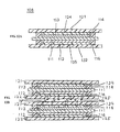
- FIG. 22 is a plan view of a process for arranging the sealing material in accordance with the third embodiment
- FIG. 23 is a conceptual view of a process for pressing in accordance with the third embodiment.
- the third embodiment differs from the first embodiment with respect to the processes of arranging the sealing material, stacking and pressing.
- first and second sealing materials 314 and 316 discontinuously extend to surround the cathode and anode.
- the notch-shaped gap portions 315 and 317 are formed where the first and second sealing materials 314 and 316 are not arranged. That is, the gap portion is formed in the charging portion.
- the reference number 311 indicates a collector.
- the process of stacking comprises a process of exhausting the bubble.
- the bubble remaining in an inner space surrounded by the collector, the electrolyte layer and the first and second sealing materials 314 and 316 is exhausted via the gap portions 315 and 317.
- the process of pressing comprises processes of exhausting the bubble and occluding the gap.
- the stack is pressed along a direction that the bipolar electrode is stacked by a press plate and a base plate, such as those previously described. At this time, a portion (charging portion) in the stack is pressed wherein the first and second sealing materials 314 and 316 are arranged.
- the bubble remaining in the inner space surrounded by the collector, the electrolyte layer and the first and second sealing materials 314 and 316 is exhausted via the gap portions 315 and 317.
- the first and second sealing materials 314 and 316 positioned around the gap portions 315 and 317 are directed toward the gap portions 315 and 317 by proceeding with the pressing operation as shown in FIG. 23 .
- the gap portions 315 and 317 are occluded by coating the gap portions 315 and 317, stopping the exhausting function.
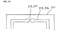
- FIG. 24 is a plan view of a modified example constructed in accordance with the third embodiment.
- the end surfaces of the first and second sealing materials 314 and 316 around the gap portions 315 and 317 have an approximately circular shape.
- the distance between the gap portions 315 and 317 is not constant. That is, the flow capabilities of the first and second sealing materials are improved as the amount of the first and second sealing materials 314 and 316 is increased. Further, since there is a portion wherein a space between the gap portions 315 and 317 is narrowed, it is possible to easily occlude the gap portions 315 and 317.
- the introduction of the bubble can be further limited in the third embodiment.
- porous separators into which the electrolyte is penetrated are overlapped with each other in the first to third embodiments.
- the bubble remains at the cathode or anode side of the bipolar electrode, it is easy to exhaust such a bubble from a surface opposite to the cathode or anode side via the separator wherein the electrolyte can penetrate therein. Further, it is also easy to exhaust the bubble from a space between the separators.
- the separators are arranged at both sides of the cathode and anode.
- the separators are arranged at both sides of the cathode and anode to thereby form a unit. This is so that the unit can be stacked by being covered and retained by the separator without exposing the cathode, the anode and the electrolyte.
- corrugation is hardly generated in the separator, and the stacking operation becomes easy, facilitating mass production.
- the separators wherein the electrolyte can penetrate are overlapped with each other, although a redundant penetrating portion (i.e., micro-crack) is generated in a part of the separator, the cathode and anode are clearly segmented from each other due to the existence of the overlapped separators. Thus, the function of the separator is secured. Accordingly, productivity may be increased.
- a redundant penetrating portion i.e., micro-crack
- first to third embodiments illustrate examples of the separators wherein two separators are overlapped with each other.
- the invention is not limited thereto since it may include separators wherein three separators are overlapped with each other, for example. In such a case, it is advantageous to form the separators as thin as possible in view of the power density.
Abstract
Description
- The invention relates generally to a bipolar battery and a method of manufacturing a bipolar battery. Aspects of the invention relate to a battery, to a battery assembly, to a method and to a vehicle.
- Recently, there has been an increased demand to reduce the amount of carbon dioxide in order to protect the environment. In the automobile industry, electric and hybrid electric vehicles have been introduced to reduce the amount of carbon dioxide. In this regard, the use of a bipolar battery has been primarily contemplated as a power source for driving the motors of these vehicles.
-
Japanese Laid-Open Patent Publication No. (Hei.) 11-204136 - In such known bipolar batteries, the cathode and the anode are provided with the electrolyte, while the separator is overlapped with either the cathode or the anode so as to form a single layer. In other words, when forming the stack, the electrolyte layer having a cathode and an anode (a layer of separator into which the electrolyte penetrates and segments a cathode and an anode, or a layer of electrolyte between the cathode or anode and the separator) is provided in the collector. The electrolyte layers are then stacked upon one another.
- When overlapping the separators, however, a bubble is introduced and maintained in the electrolyte between the cathode or anode and the separator.
- More specifically, when arranging the separator in the electrolyte layer provided to the cathode or anode, a corrugation is formed on the separator to thereby form a micro gap in the electrolyte layer. Alternatively, the bubble is introduced into the electrolyte layer due to overlapping. If the stack is formed with the remained bubble, then it becomes difficult to exhaust the bubble since the cathode and the anode exist at both surfaces of the separator via the electrolyte. Further, when the bubble remains in the stack as described above, a dead space is generated wherein an ion cannot permeate, and an electron cannot move. The dead space may become a main factor for the deterioration of power. This can be a problem when trying to improve the power density.
- It is an aim of the invention to address this issue and to improve upon known technology. Embodiments of the invention may provide a bipolar battery that has a superior battery performance by improving the power density by limiting the presence of bubbles therein. Other aims and advantages of the invention will become apparent from the following description, claims and drawings.
- Aspects of the invention therefore provide a battery, a method, a battery assembly and a vehicle as claimed in the appended claims.
- According to another aspect of the invention for which protection is sought there is provided a bipolar battery, comprising at least two bipolar electrodes arranged in a stack, each of the electrodes including a cathode formed on one side of a collector and an anode formed on an opposed side of the collector and a pair of separators arranged on opposed sides of each of the electrodes in the stack, each of the pair of separators having a permeability sufficient for an electrolyte to penetrate therein; and wherein separators of adjacent ones of the electrodes are in contact with each other.
- In an embodiment, the pair of separators is a porous membrane segmenting a cathode of a first bipolar electrode and an anode of a second, adjacent bipolar electrode, the bipolar battery further comprising an electrolyte between the cathode of the first bipolar electrode and an adjacent separator and between the anode of a second, adjacent bipolar electrode and an adjacent other separator.
- The battery may comprise an electrolyte layer arranged at cathode and anode sides of each of the bipolar electrodes; and wherein the separators of adjacent ones of the electrodes are overlapping.
- In an embodiment, the electrolyte layer is a polymer gel electrolyte or an electrolytic solution, the bipolar battery further comprising a charging portion including a charging material arranged in a space between each collector and an adjacent separator and surrounding ends of an associated cathode and anode.
- In an embodiment, the charging portion has a gap portion occluded during formation of the stack.
- In an embodiment, the electrolyte layer is the polymer gel electrolyte; and wherein a thickness of the charging portion is less than a thickness between an adjacent cathode or anode and the polymer gel electrolyte.
- The battery may comprise an electrolyte layer arranged between each anode and between each cathode and an adjacent separator and in contact with the adjacent separator, the electrolyte layer comprising the electrolyte.
- The battery may comprise a first sealing material arranged between the cathode of each of the electrodes and a first, adjacent one of the pair of separators, the first sealing material enclosing ends of the cathode and its respective electrolyte layer and a second sealing material arranged between the anode of each of the electrodes and a second, adjacent one of the pair of separators, the second sealing material enclosing ends of the anode and its respective electrolyte layer.
- The battery may comprise a sealing material arranged between a first separator of each pair of separators and a second separator of each pair of separators, the sealing material enclosing the anode, cathode, collector and electrolyte layers of a respective bipolar electrode.
- In an embodiment, the battery comprises a first sealing material arranged between the cathode of each of the electrodes and a first, adjacent one of the pair of separators, the first sealing material enclosing ends of the cathode and a second sealing material arranged between the anode of each of the electrodes and a second, adjacent one of the pair of separators, the second sealing material enclosing ends of the anode.
- According to a still further aspect of the invention for which protection is sought there is provided a method of manufacturing a bipolar battery, comprising forming a first bipolar electrode including a first cathode formed on one side of a first collector and a first anode formed on an opposed side of the first collector, arranging a first pair of separators on opposed sides the first bipolar electrode, each of the first pair of separators having a permeability sufficient for an electrolyte to penetrate therein, forming a second bipolar electrode including a second cathode formed on one side of a second collector and a second anode formed on an opposed side of the second collector, arranging a second pair of separators on opposed sides the second bipolar electrode, each of the second pair of separators having a permeability sufficient for the electrolyte to penetrate therein and stacking the first bipolar electrode and the second bipolar electrode such that a first separator of the first pair of separators and a second separator of the second pair of separators are in contact with each other.
- The method may comprise forming an electrolyte layer including the electrolyte adjacent each of the first pair of separators and the second pair of separators and interposed at cathode and anode sides of each of the first and the second bipolar electrodes, the electrolyte layer comprising the electrode; and wherein stacking the first bipolar electrode and the second bipolar electrode further includes overlapping the first separator and the second separator with each other.
- In an embodiment, each of the separators is a porous membrane, the method further comprising forming an electrolyte layer including the electrolyte between the first separator and the second separator, the first separator and the second separator being overlapped after stacking.
- The method may comprise forming a respective electrolyte layer including the electrolyte between the first cathode and a first, adjacent separator of the first pair of separators and between the first anode and a second, adjacent separator of the first pair of separators and forming a respective electrolyte layer including the electrolyte between the second cathode and a first, adjacent separator of the second pair of separators and between the second anode and a second, adjacent separator of the second pair of separators.
- In an embodiment, the electrolyte of each of the electrolyte layers is a polymer gel electrolyte or an electrolytic solution, the method further comprising prior to stacking, arranging a sealing material for forming a charging portion and arranging a charging material in a space between the first collector and each of the first pair of separators to surround edges of the first cathode and the first anode.
- In an embodiment, a gap portion is formed at the charging portion, the method further comprising exhausting a bubble remaining in an inner space of the first electrode formed by the collector, at least one of the first pair of separators and the charging material via the gap portion.
- The method may comprise occluding a gap of the gap portion by pressing the charging portion along a stacking direction of the stack after exhausting the bubble.
- In an embodiment, the electrolyte is the polymer gel electrolyte, and a thickness of the charging portion is less than a thickness between the first cathode or first anode and the polymer gel electrolyte.
- For example, a bipolar battery taught herein may comprise at least two bipolar electrodes arranged in a stack, each of the electrodes including a cathode formed on one side of a collector and an anode formed on an opposed side of the collector, and a pair of separators arranged on opposed sides of each of the electrodes in the stack, each of the pair of separators having a permeability sufficient for an electrolyte to penetrate therein. Separators of adjacent ones of the electrodes are in contact with each other.
- In another example, a method comprises forming a first bipolar electrode including a first cathode formed on one side of a first collector and a first anode formed on an opposed side of the first collector, arranging a first pair of separators on opposed sides the first bipolar electrode, each of the first pair of separators having a permeability sufficient for an electrolyte to penetrate therein, forming a second bipolar electrode including a second cathode formed on one side of a second collector and a second anode formed on an opposed side of the second collector, arranging a second pair of separators on opposed sides the second bipolar electrode, each of the second pair of separators having a permeability sufficient for the electrolyte to penetrate therein, and stacking the first bipolar electrode and the second bipolar electrode such that a first separator of the first pair of separators and a second separator of the second pair of separators are in contact with each other.
- Within the scope of this application it is envisaged that the various aspects, embodiments, examples, features and alternatives set out in the preceding paragraphs, in the claims and/or in the following description and drawings may be taken individually or in any combination thereof.
- The present invention will now be described, by way of example only, with reference to the accompanying drawings in which:
-
FIG. 1 is a cross-sectional view of a bipolar battery constructed in accordance with a first embodiment of the invention; -
FIG. 2 is a cross-sectional view of the bipolar battery shown inFIG. 1 ; -
FIG. 3 is a perspective view of a battery assembly configured to use the bipolar battery shown inFIG. 1 ; -
FIG. 4 is a diagram of a vehicle wherein the battery assembly shown inFIG. 3 is mounted; -
FIG. 5 is a flow diagram of a method for manufacturing the bipolar battery constructed in accordance with the first embodiment; -
FIG. 6 is a flow diagram of a process for forming an assembly unit shown inFIG. 5 ; -
FIG. 7 is a flow diagram of a process for forming an electrode shown inFIG. 6 ; -
FIG. 8 is a flow diagram of a process for forming an electrode shown inFIG. 6 ; -
FIG. 9 is a cross-sectional view of a process for arranging an electrode shown inFIG. 6 ; -
FIG. 10 is a plan view of a process for arranging a sealing material shown inFIG. 6 ; -
FIG. 11 is a cross-sectional view of a process for arranging a sealing material shown inFIG. 6 ; -
FIG. 12A is a cross-sectional view of the assembly unit and a process for arranging the separator shown inFIG. 6 ; -
FIG. 12B is a cross-sectional view when the assembly unit shown inFIG. 12A is partially stacked in the process of forming a bonded body shown inFIG. 5 ; -
FIG. 13 is a flow diagram of forming the bonded body shown inFIG. 5 ; -
FIG. 14 is a cross-sectional view of a process for setting the assembly unit shown inFIG. 13 ; -
FIG. 15 is a diagram of processes for stacking and pressing as shown inFIG. 13 ; -
FIG. 16 is a diagram of a process for forming a sealing layer shown inFIG. 13 ; -
FIG. 17 is a diagram of a process for forming an interface shown inFIG. 13 ; -
FIG. 18 is a diagram of a process for initial charging as shown inFIG. 13 ; -
FIG. 19 is a cross-sectional of a modified example constructed in accordance with the first embodiment; -
FIG. 20 is a flow diagram of a process for forming a collector in accordance with a second embodiment of the invention; -
FIG. 21 is a diagram of a process for penetration of a sealing material shown inFIG. 20 ; -
FIG. 22 is a plan view of a process for arranging a sealing material in accordance with a third embodiment of the invention; -
FIG. 23 is a conceptual view of a process for pressing in accordance with the third embodiment; and -
FIG. 24 is a plan view of a modified example constructed in accordance with the third embodiment. -
FIG. 1 is a cross-sectional view of a bipolar battery constructed in accordance with a first embodiment of the invention.FIG. 2 is a cross-sectional view of the bipolar battery shown inFIG. 1 .FIG. 3 is a perspective view of a battery assembly configured to use the bipolar battery shown inFIG. 1 .FIG. 4 is a diagram of a vehicle wherein the battery assembly shown inFIG. 2 is mounted. - In a
bipolar battery 10 constructed in accordance with the first embodiment (shown inFIG. 2 ), astack 100 is formed by preparing an electrolyte layer 120 in a bipolar electrode and stacking the electrolyte layers upon one another. The bipolar electrode has ananode 112, acathode 113 and acollector 111. Thecathode 113 is arranged at one side surface of thecollector 111, and theanode 112 is arranged at another side surface of thecollector 111. That is, thecollector 111 is placed between thecathode 113 and theanode 112. - The electrolyte layer 120 has a
layer comprising separators separators cathode 113 or theanode 112. Theseparators cathode 113 or theanode 112, wherein the electrolyte can penetrate into such membranes. The electrolyte can be, for example, a polymer gel electrolyte (gel polymer-based electrolyte). - That is, since the
separators separators separators cathode 113 oranode 112. Further, it is also easy to exhaust the bubble from a space between theseparators separators stack 100, while theseparators separators separators - The
bipolar battery 10 also has first and second sealing layers 115 and 117. Thefirst sealing layer 115 is arranged at one side surface of thecollector 111 and extended to surround an end of thecathode 113. The electrolyte layer 120 is arranged to cover thecathode 113 and thefirst sealing layer 115. Thesecond sealing layer 117 is position-adjusted with thefirst sealing layer 115, thereby being arranged at another side surface of thecollector 111 and extended to surround an end of theanode 112. A region wherein the first and second sealing layers 115 and 117 are arranged is referred to as a charging portion. - The
collector 111 is, for example, a stainless steel foil. However, thecollector 111 is certainly not limited thereto and may include an aluminum foil, a clad material of nickel and aluminum, a clad material of copper and aluminum, or a plating material of a combination of the these metals. - An anode active material of the
anode 112 is, for example, a hard carbon (a non-graphitized carbon material). The anode active material is certainly not limited thereto since it may include a graphite-based carbon material or a lithium-transition metallic composite oxide. In certain embodiments, the anode active material composed of carbon and the lithium-transition metallic composite oxide is advantageous in terms of capacity and power. - A cathode active material of the
cathode 113 is, for example, LiMn2O4, although it is certainly not limited thereto. The lithium-transition metallic composite oxide is desirable in terms of capacity and power. - Thicknesses of the
cathode 113 andanode 112 may be set depending on the purpose of use (e.g., emphasis on power or energy) or ion conductivity. - A charging material constituting the first and second sealing layers 115 and 117 is, for example, one-liquid uncured epoxy resin. However, the charging material is not limited thereto and may include other thermosetting resins (polypropylene or polyethylene) or thermoplastic resins. In certain embodiments, it is beneficial to select a material having a desired sealing effect depending on the type of application.
- A material for each
separator - A host polymer of the electrolyte is, for example, PVDF-HFP (copolymer of polyvinylidene fluoride and hexafluoropropylene) containing 10% of HFP (hexafluoropropylene) copolymer. However, the host polymer is not limited thereto and may include other polymers without lithium ion conductivity or polymer (solid polymer electrolyte) with ion conductivity. Other polymers without lithium ion conductivity, for example, include PAN (polyacrylonitile) and PMMA (polymethylmethacrylate). A polymer with ion conductivity, for example, is PEO (polyethylene oxide) or PPO (polypropylene oxide).
- An electrolytic solution retained in the host polymer includes, for example, an organic solvent composed of PC (propylene carbonate) and EC (ethylene carbonate), and lithium salt (LiPF6) as a support salt. The organic solvent is not limited to PC and EC since it may include other ring-type carbonate classes, chain-type carbonate classes such as dimethylcarbonate and ether classes such as tetrahydrofuran. The lithium salt can alternatively include other inorganic anionic salts and organic anionic salts such as LiCF3SO3 instead of LiPF6.
- As shown generally in
FIGS. 1 and 2 , thebipolar battery 10 is housed within anexterior case 104 in the form of astack 100 of a unit bipolar battery, thereby preventing an impact from the outside or environmental deterioration. Terminal leads 101 and 102 composed of a high conductive member are connected torespective collectors 111 placed at the outermost layer of thestack 100. The high conductive member includes, for example, aluminum, copper, titan, nickel, stainless or alloys thereof. Further, thereference number 103 indicates a reinforcing plate. - The terminal leads 101 and 102 extend to an outer portion of the
exterior case 104, and each serves as an electrode tab for extracting the current from thestack 100. Further, by arranging an electrode tab of an independent separate member and connecting to the terminal leads 101 and 102 directly or by using a lead, it is possible to extract the current from thestack 100. - To reduce weight and thermal conductivity, the
exterior case 104 can be composed of a sheet material such as polymer-metallic composite laminate film wherein metals such as aluminum, stainless, nickel or copper (including alloys thereof) are coated by an insulator such as a polypropylene film. Further, theexterior case 104 is formed by bonding a part or the entire outer periphery of the case via thermal fusion. - It is possible to use the
bipolar battery 10 independently. Optionally, for example, it is possible to use thebipolar battery 10 in the form of abattery assembly 130 as shown inFIG. 3 . Thebattery assembly 130 is constituted by serializing and/or parallelizing thebipolar battery 10 and multi-connecting thebipolar batteries 10. Thebattery assembly 130 hasconductive bars conductive bars bipolar battery 10. - When the
bipolar battery 10 is connected and constituted, the capacity and voltage can be freely adjusted via an appropriate serialization or parallelization. A connecting method includes, for example, an ultrasonic welding operation, a thermal welding operation, a laser welding operation, a rivet operation, a caulking operation or an electronic beam. - By serializing and/or parallelizing and multi-connecting the
battery assemblies 130, it is possible to provide a battery assembly module (a large scale battery assembly) 136 as shown inFIG. 4 . Since thebattery assembly module 136 can secure a higher power, it is possible, for example, to be mounted as a power source for driving a motor of avehicle 138. The vehicle includes, for example, an electric vehicle, a hybrid electric vehicle or an electric train. - The
battery assembly module 136, for example, can perform very elaborate control such as performing a control of charging in every interiorbipolar battery 10 or everybattery assembly 130. Accordingly, it is possible to achieve functional improvements such as an extension of driving distance per charging at one time or an extension of lifetime of a battery mounted on a vehicle. -
FIG. 5 is a flow diagram of a method for manufacturing a bipolar battery in accordance with the first embodiment. The method includes a step of forming an assembly unit as a sub-assembly unit wherein the electrolyte and the separator are sequentially arranged at both sides of the bipolar electrode, a step of forming a bonded body as an assembly step for forming the stack (bonded body) wherein the assembly units (sub-assembly units) are stacked and integrated and a step of assembling for housing the integrated stack within the exterior case. - Forming the bonded body (assembly step) comprises a stacking step for stacking the bipolar batteries upon one another by interposing the electrolyte layer, as will be explained below. In the stacking step, since the separators are overlapped with each other wherein the electrolytes can penetrate, it becomes easy to exhaust such a bubble left at the cathode or anode side of the bipolar electrode from a surface opposite to the cathode or anode side via the separator, which has a property for the electrolytes to penetrate therein. Further, it is also easy to exhaust the bubble from a space between the separators.
- That is, only a single layer results in a situation where the cathode and anode sides exist at both surfaces of the separator. This makes it difficult to exhaust the bubble. Here, however, since the cathode or anode side exists at one side surface of the separator and the separator exists at another side surface, it becomes easy to exhaust the remaining bubble from one side surface to another side surface. Further, it is also easy to exhaust the bubble from a space between the separators.
-
FIG. 6 is a flow diagram of the process for forming the assembly unit shown inFIG. 5 .FIG. 7 is a plan view of the process for forming the electrode shown inFIG. 6 , whileFIG. 8 is a cross-sectional view of the process for forming the electrode shown inFIG. 6 .FIG. 9 is a cross-sectional view of the process for arranging the electrolyte shown inFIG. 6 , whileFIG. 10 is a plan view of the process for arranging the sealing material shown inFIG. 6 .FIG. 11 is a cross-sectional view of the process for arranging the sealing material shown inFIG. 6 .FIG. 12A is a cross-sectional view of the process for arranging the separator shown inFIG. 6 and theassembly unit 108 as a sub-assembly. - As shown in
FIG. 6 , the process of forming an assembly unit can include the steps of forming the electrode, arranging the electrolyte, arranging the sealing material and arranging the separator. - In this embodiment, cathode slurry is first adjusted in the process of forming the electrode. The cathode slurry is prepared, for example, to have a cathode active material of 85 wt%, a conductive auxiliary agent of 5 wt% and a binder of 10 wt%. The cathode slurry obtains a desired viscosity by adding a viscosity adjusting solvent therein. The cathode active material is, for example, LiMn2O4, while the conductive auxiliary agent is acetylene black. The binder is PVDF (polyvinylidene fluoride). The viscosity adjusting solvent is NMP (N-methyl-2-pyrolidone). The cathode slurry is applied to one side surface of the
collector 111 composed of stainless steel foil. - The conductive auxiliary agent, for example, may include carbon black or graphite. The binder and the viscosity adjusting solvent are not limited to PVDF and NMP.
- Next, anode slurry is adjusted. The anode slurry is prepared, for example, to have an anode active material of 90 wt% and a binder of 10 wt%. The anode slurry obtains a desired viscosity by adding a viscosity adjusting solvent therein. The anode slurry is applied to another side surface of the
collector 111. In this example, the anode active material is hard carbon, and the binder and the viscosity adjusting solvent are PVDF and NMP. The anode slurry is applied to another side surface of the collector 1 11. - Applied membranes of the cathode slurry and the anode slurry are, for example, dried by using a vacuum oven and respectively form the
cathode 113 composed of the cathode active material and theanode 112 composed of the anode active material (seeFIGS. 7 and 8 ). At this time, NMP is removed by being volatilized. - Thicknesses of the
cathode 113 and theanode 112 are certainly not limited and may be set depending on the purpose of use (e.g., emphasis on power or energy) or ion conductivity. - In the process of arranging the electrolyte, the
electrolytes cathode 113 and theanode 112, respectively (seeFIG. 9 ). - The
electrolytes Electrolytes - The electrolytic solution includes an organic solvent composed of PC (propylene carbonate) and EC (ethylene carbonate) and lithium salt (LiPF6) as a support salt. The concentration of the lithium salt is, for example, 1 M.
- The host polymer is, for example, PVDF-HFP (copolymer of polyvinylidene fluoride and hexafluoropropylene) containing 10% of HFP (hexafluoropropylene) copolymer. A viscosity preparing solvent is DMC (dimethyl carbonate). The viscosity preparing solvent is not limited to DMC.
- With reference to
FIG. 10 , in the process of arranging the sealing material afirst sealing material 114 is first arranged so as to extend an outer periphery in the cathode side wherein thecollector 111 is exposed as well as an edge of thecathode 113. For the arrangement of thefirst sealing material 114, an application is made using a dispenser, for example. - Next, as shown in
FIG. 11 , asecond sealing material 116 is arranged to extend an outer periphery in the anode side wherein thecollector 111 is exposed as well as an edge of theanode 112. At this time, thesecond sealing material 116 is positioned so as to be opposite (and overlapped) to thefirst sealing material 114. For the arrangement of thesecond sealing material 116, for example, an application is made using a dispenser is applied. Further, the first and second sealing materials are charging materials composed of a one-liquid uncured epoxy resin in this example. - As shown in
FIG. 12A , in the process of arranging the separator, theseparators collector 111. By doing so, theassembly unit 108 is formed wherein theelectrolytes separators separators - As such, since the
assembly unit 108 is arranged so as to cover both the cathode and anode side surfaces of thecollector 111, theassembly unit 108 becomes a sub-assembly component packed by a separator such as PE without exposing the electrode and electrolyte. To this end, delivery becomes easy without altering or deteriorating the electrode and electrolyte. Further, since the sub-assembly components are stacked upon one another in the following process, a stacking operation becomes very easy. - Further, the assembly unit (sub-assembly) 108 can be housed in a vacuum container or suctioned from the edges of the separators at both sides by using a vacuum cup. Since the bubble can be exhausted from the
electrolytes separators stack 100, as is explained next. - In the process of arranging the sealing material, a charging portion is formed in a space between the
collector 111 and the electrolyte layer 120. The charging material is arranged in the charging portion so as to surround the edges of thecathode 113 and theanode 112. - Further, in the process of arranging the sealing material according to certain embodiments, it is advantageous that a thickness of the
first sealing material 114 is predetermined to be less than a total thickness of thecathode 113 andelectrolyte 124. In addition thereto, in some of these embodiments, it is advantageous that a thickness of thesecond sealing material 116 is predetermined to be less than a total thickness of theanode 112 andelectrolyte 125. Since theseparators electrolytes second sealing materials second sealing materials -
FIG. 12B is a cross-sectional view when theassembly unit 108 shown inFIG. 12A is partially stacked in the process of forming the bonded body shown inFIG. 5 .FIG. 13 is a flow diagram of forming the bonded body (assembly process) shown inFIG. 5 , whileFIG. 14 is a cross-sectional view of a process for setting the assembly unit shown inFIG. 13 .FIG. 15 is a diagram of a process for stacking the assembly unit and for pressing shown inFIG. 13 .FIG. 16 is a diagram of a process for forming a sealing layer shown inFIG. 13 , whileFIG. 17 is a diagram of a process for forming an interface shown inFIG. 13 .FIG. 18 is a diagram of a process for the initial charging shown inFIG. 13 . - As shown in
FIG. 13 , the process of forming the bonded body comprises the steps of setting and stacking the assembly unit, pressing and forming a sealing layer, forming an interface, initial charging and exhausting the bubble. - In the process of setting the assembly unit, as shown in
FIG. 14 , the assembly units 108 (as a plurality of sub-assemblies) are sequentially set in amagazine 150. At this time, as shown inFIG. 12A , since theseparators electrolytes second sealing materials electrolytes assembly unit 108, theelectrolytes second sealing materials assembly unit 108 to thereby secure the preferred working property. - Referring now back to
FIG. 14 , in order to avoid interference when setting theassembly unit 108, themagazine 150 has aclamp mechanism 152, which is in a frame shape and is capable of embracing the outer peripheral portion of theassembly unit 108. - The
clamp mechanism 152 is arranged in a stacking direction with an interspacing such that theassembly units 108 do not contact each other. The stacking direction is vertical to a surface direction of theassembly unit 108. - The
clamp mechanism 152 is configured, for example, to have an elastic member composed of a spring and to be retainable and supportable when assigning a tensile force to theassembly unit 108 based on an elastic force such that corrugation is not generated. Other mechanisms to perform a clamping function are also possible. Since such mechanisms are known in the art, a detailed explanation thereof is omitted herein. - In the process of stacking the assembly unit, as shown in
FIG. 15 , themagazine 150 is arranged within avacuum treatment device 160. Thestack 100 of theassembly unit 108 is formed under vacuum with a range of, for example 0.2 to 0.5 × 10⁵ Pa. - Since the
electrolytes second sealing materials separators assembly unit 108 to thereby secure the working properties. Further, since theseparators assembly unit 108 is under vacuum, the bubble is introduced into a stacking interface of the electrode and the electrolyte layer, passes through the separator and is efficiently exhausted from a space between the separators to the outside. This further reduces the remaining bubble. -
FIG. 12B is a cross-sectional view when a part of theassembly unit 108 is stacked in the process of forming the bonded body. Although theseparators FIG. 12B shows theseparators FIG. 12B , since theseparators 121 and 122 (that is, two sheets) are overlapped with each other wherein theelectrolytes cathode side 113 oranode side 112 of the bipolar electrode, it becomes easy to exhaust the bubble N from a surface opposite to thecathode side 113 oranode side 112 via theseparators electrolytes separators electrolytes separators - Further, as discussed above, the bubble N can be exhausted via the
separators assembly unit 108. Optionally, the bubble N can be exhausted from a space between theseparators assembly unit 108 such as pressing or forming an interface. Also, the bubble N can be exhausted after being cased. - Therefore, since the dead space wherein the ion is not permeable and the electron cannot be moved is restrained, the movement of the ion and electron is not impeded during the use thereof, thereby achieving high power density.
- A method of forming the
stack 100 comprises, for example, sequentially releasing theclamp mechanism 152 for embracing theassembly unit 108 from a lower side so as to be stacked at a rest arranged at a lower portion of themagazine 150. The method is certainly not limited thereto. - Further, in addition to sequentially releasing the clamp mechanism from a lower side to an upper side, the rest may be moved from a lower side to an upper side of the
magazine 150 to stack thestack 108 nearby without being exceedingly displaced. Alternatively, the magazine may be moved from the upper side to the lower side by fastening the rest. - The
vacuum treatment device 160 shown inFIG. 15 has anapparatus 162 for performing a vacuum function, anapparatus 170 for performing a pressing function and acontroller 178. - The vacuuming
apparatus 162 has avacuum chamber 163, avacuum pump 164 and apiping system 165. Thevacuum chamber 163 has a detachable (openable) cover portion and a fixed base wherein themagazine 150 and thepressing apparatus 170 are arranged. Thevacuum pump 164 is, for example, centrifugal and is used for forming an inner portion of thevacuum chamber 163 in a vacuum state. Thepiping system 165 is used for connecting thevacuum pump 164 and thevacuum chamber 163, and a leak valve (not shown) is arranged therein. - The
pressing apparatus 170 has abase plate 171 and apress plate 173 spaced apart from thebase plate 171. Optionally, an elastic body in a sheet-shape may be arranged on thebase plate 171 and thepress plate 173. Thecontroller 178 is used for controlling the movement or pressing force of thebase plate 173. Thecontroller 178 can be, for example, a microcomputer including a random access memory (RAM), a read-only memory (ROM) and a central processing unit (CPU) in addition to various input and output connections. Generally, the control functions are performed by execution by the CPU of one or more programs stored in ROM. - As shown in
FIG. 15 , in the process of pressing, thestack 100 is pressed by the press plate and thebase plate 171 while maintaining a vacuum state. By doing so, the first andsecond sealing materials - Referring now to
FIG. 16 , since thestack 100 is arranged in anoven 190 and then heated in the process of forming the sealing layer, the first andsecond sealing materials stack 100 may be thermally cured, thereby forming the first and second sealing layers 115 and 117. The heating condition is, for example, 80°C. Heating the stack can be performed other than in an oven. - Although a lithium secondary battery dislikes moisture, since the first and second sealing layers 115 and 117 are composed of resin, the introduction of moisture cannot be avoided. To this end, the desired thicknesses of the first and
second sealing materials - Optionally, a thermoplastic resin may be applied to the first and
second sealing materials second sealing materials - In the process of forming an interface, since the
stack 100 is arranged in apressing apparatus 180 and pressed under heating, theelectrolytes separators stack 100 and a gel interface is formed thereon as seen inFIG. 17 . The heating and pressing conditions are, for example, 80°C and 1 to 2 × 10⁶ Pa, respectively. By doing this heating and pressing, theassembly unit 108 is stacked so that an integrated stack (bonded body) 100 can be obtained. - Here, when the
electrolytes separators stack 100, although the bubble N remains within theelectrolytes separators electrolyte 124 via theseparator 121, exhausted from theelectrolyte 125 via theseparator 122 and exhausted from a space between theseparators - The
pressing apparatus 180 has abase plate 181, apress plate 183 close to but spaced apart from thebase plate 181, a lowerportion heating part 185, an upperportion heating part 187 and acontroller 188. The lowerportion heating part 185 and the upperportion heating part 187 have a resistance heating element, for example, and the twoparts base plate 181 and thepress plate 183 and are used to increase the temperature of thebase plate 181 and thepress plate 183. Thecontroller 188, like thecontroller 178, is used for controlling the movement and pressing force of thepress plate 183 and is also used for controlling the temperature of the lowerportion heating part 185 and the upperportion heating part 187. - Optionally, either of the lower
portion heating part 185 or the upperportion heating part 187 may be omitted. Alternatively, the lowerportion heating part 185 and the upperportion heating part 187 may be arranged at an outer portion of thebase plate 181 and thepress plate 183. Further, a sheet-shaped elastic body may be arranged in thebase plate 181 and thepress plate 183. - As shown in
FIG. 18 , the operation of initially charging described with respect toFIG. 13 is performed by a charging/dischargingdevice 192 electrically connected to thestack 100. A bubble is generated. The initial charging condition is, for example, a capacity base approximately calculated from an application weight of the cathode, such as 4 hours in 21 V-0.5 C. - Again referring to
FIG. 13 , in the process of exhausting the bubble, for example, the bubble in a center portion of thestack 100 is moved to the outer periphery and is then removed by pressing a roller against a surface of thestack 100. Further, since the bubble is sufficiently exhausted in the process of forming the interface, the process of exhausting the bubble is not essential. However, it is possible to improve the power density of the battery by further limiting the bubble via such a process. - In the process of casing, the integrated stack (bonded body) 100 is housed within the exterior case 104 (see
FIG. 2 ) to thereby manufacture the bipolar battery 10 (seeFIGS. 1 and 2 ). Theexterior case 104 is formed by arranging thestack 100 between two sheet-shaped exterior materials and bonding an outer periphery of the exterior materials. The exterior materials can be polymer-metallic composite laminate film coated by an insulator such as a polypropylene film and bonded by applying a thermal fusion. - Further, it is possible to achieve the high capacity and/or high power of an additional layer of the bipolar battery by further stacking the
integrated stack 100 upon another and then housing the arrangement within theexterior case 104. Optionally, it is possible to perform the processes of stacking and pressing in atmospheric conditions or the processes of forming the sealing layer and the interface under vacuum. - By appropriately selecting the
electrolytes second sealing materials second sealing materials stack 100 may be added between the processes of forming the sealing layer and forming the interface. -
FIG. 19 is a cross-sectional view of a modified example constructed in accordance with the first embodiment. In the example of the first embodiment previously described, the first andsecond sealing materials collector 111 and theseparators cathode 113 andanode 112. However, a sealing structure is certainly not limited to the above. As shown inFIG. 19 , for example, it is possible to arrange a sealingmaterial 118 so as to extend to the edges of thecathode 113, thecollector 111 and theanode 112. - As such, the first embodiment can provide a bipolar battery that minimizes the introduction of a bubble and a method of manufacturing such a battery.
- Further, since the polymer gel electrolyte is a thermoplastic containing the electrolyte within a polymer framework, liquid leakage is prevented to thereby prevent liquid junction so as to constitute the bipolar battery having high reliability. Also, the polymer gel electrolyte is certainly not limited to thermoplastic since it may be thermosetting. In such a case, the liquid leakage is prevented by hardening the electrolyte layer by pressing under heating to thereby prevent the liquid junction.
- The surface pressure in the processes of pressing and forming the interface is certainly not limited to 1 to 2×10⁶ Pa since it may be appropriately established by considering the material properties such as the strength of materials of the
stack 100. The heating temperature in the process of forming the sealing layer is not limited to 80 °C. It can, for example, be anywhere within a range between 60°C and 150°C when considering the material properties such as the heat resistance of the electrolytic solution or the hardening temperature of the first sealing material 114 (first sealing layer 115) and the second sealing material 116 (sealing layer 117). - The
electrolytes cathode 113 andanode 112 by using a micropipette and sank therein (seeFIG. 9 ) - The electrolytic solution includes an organic solvent composed of propylene carbonate (PC) and ethylene carbonate (EC), a lithium salt (such as LiPF6) as a support salt and a small quantity of surfactant. The concentration of the lithium salt is, for example, 1 M.
- The organic solvent is certainly not limited to PC and PE since it may include other ring-type carbonate classes, chain-type carbonate classes such as dimethyl carbonate or ether classes such as tetrahyrdofuran. The lithium salt is also not limited to LiPF6 since it may include other inorganic anionic salts and organic anionic salts such as LiCF3SO3.
- Next, the second embodiment of the invention is explained with initial reference to
FIG. 20 , which is a flow diagram of a process for forming a bonded body in accordance with the second embodiment.FIG. 21 is a diagram of a process for penetrating a sealing material shown inFIG. 20 . - The second embodiment differs from the first embodiment in that it comprises a process of penetration of a sealing material between the processes of pressing and forming the sealing layer.
- Referring now to
FIG. 21 , in order to limit the bubble from remaining in an inner portion surrounded by the first and second sealing materials, when the thicknesses of the first and second sealing materials are set to be less than a total thickness of the cathode and electrode and a total thickness of the anode and electrolyte, respectively, the pressing force is not sufficiently transferred to a portion (charging portion) wherein the first and second sealing materials are arranged in spite of pressing astack 200. This causes a sealing shortage. - To this end, the first and second sealing materials are sufficiently penetrated into the separator by adding a process of penetration of the sealing material in order to press the charging portion in the
stack 200 by using apressing device 280. - In the process of forming the sealing layer, the portion into which the first and second sealing materials are penetrated is heated so as to be thermally cured. Thus, the adhesive property of the first and second sealing layers is improved compared to the first embodiment. Further, the first and second sealing materials penetrate into a portion of the separator of the manufactured bipolar battery opposite to the first and second sealing layers.
- The
pressing device 280 has abase plate 281 in which thestack 200 is arranged, apress plate 283 close to but spaced apart from thebase plate 281 and a controller similar tocontrollers FIG. 21 . Thepress plate 283 is divided to have acenter press plate 284 and an outerperiphery press plate 285. - The
center press plate 284 is used for supporting a portion of thestack 200 wherein an electrode portion (i.e., the cathode and anode) is arranged. The outerperiphery press plate 285 is used for pressing a charging portion of thestack 200. The controller is used for controlling the movements or pressing force of thecenter press plate 284 and the outerperiphery press plate 285. Therefore, thepressing device 280 is capable of pressing only the charging portion by using the outerperiphery press plate 285 of thestack 200 arranged in thebase plate 281. - Although not necessary, it is beneficial that the pressing operation by the outer
periphery press plate 285 occur after pressing the electrode portion of thestack 200 by thecenter press plate 284. In such a case, it is possible to move the bubble in the electrode portion to the outer peripheral portion, further minimizing the remaining bubble in the electrode portion. - As such, compared to the first embodiment, sealing properties are further improved. Further, it is possible to appropriately integrate the processes of pressing and penetrating the sealing material as necessary.
- Next, a third embodiment of the invention is explained with reference to
FIGS. 22 and 23. FIG. 22 is a plan view of a process for arranging the sealing material in accordance with the third embodiment, whileFIG. 23 is a conceptual view of a process for pressing in accordance with the third embodiment. - The third embodiment differs from the first embodiment with respect to the processes of arranging the sealing material, stacking and pressing.
- Referring first to
FIG. 22 , in the process of arranging the sealing material, first and second sealing materials 314 and 316 discontinuously extend to surround the cathode and anode. The notch-shaped gap portions 315 and 317 are formed where the first and second sealing materials 314 and 316 are not arranged. That is, the gap portion is formed in the charging portion. Further, thereference number 311 indicates a collector. - The process of stacking comprises a process of exhausting the bubble. When forming the stack, the bubble remaining in an inner space surrounded by the collector, the electrolyte layer and the first and second sealing materials 314 and 316 is exhausted via the gap portions 315 and 317.
- The process of pressing comprises processes of exhausting the bubble and occluding the gap. The stack is pressed along a direction that the bipolar electrode is stacked by a press plate and a base plate, such as those previously described. At this time, a portion (charging portion) in the stack is pressed wherein the first and second sealing materials 314 and 316 are arranged.
- To this end, at the beginning of pressing, the bubble remaining in the inner space surrounded by the collector, the electrolyte layer and the first and second sealing materials 314 and 316 is exhausted via the gap portions 315 and 317. Further, the first and second sealing materials 314 and 316 positioned around the gap portions 315 and 317 are directed toward the gap portions 315 and 317 by proceeding with the pressing operation as shown in
FIG. 23 . The gap portions 315 and 317 are occluded by coating the gap portions 315 and 317, stopping the exhausting function. - In such a case, it is possible to move the bubble in the electrode portion included in the stack to an outer periphery via the gap portions 315 and 317 until the gap portions 315 and 317 are occluded. Thus, the remaining bubble in the electrode portion is further limited.
-
FIG. 24 is a plan view of a modified example constructed in accordance with the third embodiment. In this modified example, the end surfaces of the first and second sealing materials 314 and 316 around the gap portions 315 and 317 have an approximately circular shape. The distance between the gap portions 315 and 317 is not constant. That is, the flow capabilities of the first and second sealing materials are improved as the amount of the first and second sealing materials 314 and 316 is increased. Further, since there is a portion wherein a space between the gap portions 315 and 317 is narrowed, it is possible to easily occlude the gap portions 315 and 317. - As mentioned above, compared to the first embodiment, the introduction of the bubble can be further limited in the third embodiment.
- Further, the porous separators into which the electrolyte is penetrated are overlapped with each other in the first to third embodiments. Thus, although the bubble remains at the cathode or anode side of the bipolar electrode, it is easy to exhaust such a bubble from a surface opposite to the cathode or anode side via the separator wherein the electrolyte can penetrate therein. Further, it is also easy to exhaust the bubble from a space between the separators.
- Also, although the cathode and anode are positioned at both sides of the bipolar electrode, the separators are arranged at both sides of the cathode and anode. To this end, the separators are arranged at both sides of the cathode and anode to thereby form a unit. This is so that the unit can be stacked by being covered and retained by the separator without exposing the cathode, the anode and the electrolyte. Thus, corrugation is hardly generated in the separator, and the stacking operation becomes easy, facilitating mass production.
- Further, since the separators wherein the electrolyte can penetrate are overlapped with each other, although a redundant penetrating portion (i.e., micro-crack) is generated in a part of the separator, the cathode and anode are clearly segmented from each other due to the existence of the overlapped separators. Thus, the function of the separator is secured. Accordingly, productivity may be increased.
- Also, the first to third embodiments illustrate examples of the separators wherein two separators are overlapped with each other. However, the invention is not limited thereto since it may include separators wherein three separators are overlapped with each other, for example. In such a case, it is advantageous to form the separators as thin as possible in view of the power density.
- The above-described embodiments have been described in order to allow easy understanding of the invention and do not limit the invention. On the contrary, the invention is intended to cover various modifications and equivalent arrangements included within the scope of the appended claims, which scope is to be accorded the broadest interpretation so as to encompass all such modifications and equivalent structure as is permitted under the law.
- This application claims priority from
Japanese Patent Application Nos. 2006-324678, filed 30th November 2006 2007-260223, filed 3rd October 2007
Claims (15)
- A bipolar battery, comprising:at least two bipolar electrodes arranged in a stack, each of the electrodes comprising a cathode formed on one side of a collector and an anode formed on an opposed side of the collector; anda pair of separators arranged on opposed sides of each of the electrodes in the stack, each of the pair of separators having a permeability sufficient for an electrolyte to penetrate therein;wherein separators of adjacent ones of the electrodes are in contact with each other.
- A battery as claimed in claim 1, wherein the pair of separators comprises a porous membrane segmenting a cathode of a first bipolar electrode and an anode of a second, adjacent bipolar electrode, and wherein the battery comprises an electrolyte between the cathode of the first bipolar electrode and an adjacent separator and between the anode of a second, adjacent bipolar electrode and an adjacent other separator.
- A battery as claimed in any preceding claim, comprising an electrolyte layer arranged at cathode and anode sides of each of the bipolar electrodes; and wherein the separators of adjacent ones of the electrodes are overlapping.
- A battery as claimed in claim 3, wherein the electrolyte layer comprises a polymer gel electrolyte or an electrolytic solution, and wherein the battery comprises a charging portion including a charging material arranged in a space between each collector and an adjacent separator and surrounding ends of an associated cathode and anode.
- A battery as claimed in claim 4, wherein the charging portion comprises a gap portion occluded during formation of the stack.
- A battery as claimed in claim 4 or claim 5, wherein the electrolyte layer comprises the polymer gel electrolyte and wherein a thickness of the charging portion is less than a thickness between an adjacent cathode or anode and the polymer gel electrolyte.
- A battery as claimed in any preceding claim, comprising an electrolyte layer arranged between each anode and between each cathode and an adjacent separator and in contact with the adjacent separator, the electrolyte layer comprising the electrolyte.
- A battery as claimed in claim 7, comprising a sealing material arranged between a first separator of each pair of separators and a second separator of each pair of separators, the sealing material enclosing the anode, cathode, collector and electrolyte layers of a respective bipolar electrode.
- A battery as claimed in any preceding claim, comprising:a first sealing material arranged between the cathode of each of the electrodes and a first, adjacent one of the pair of separators,a second sealing material arranged between the anode of each of the electrodes and a second, adjacent one of the pair of separators;wherein the first sealing material optionally encloses ends of the cathode and the second sealing material optionally encloses ends of the anode.
- A method of manufacturing a bipolar battery, comprising:forming a first bipolar electrode comprising a first cathode formed on one side of a first collector and a first anode formed on an opposed side of the first collector;arranging a first pair of separators on opposed sides the first bipolar electrode, each of the first pair of separators having a permeability sufficient for an electrolyte to penetrate therein;forming a second bipolar electrode comprising a second cathode formed on one side of a second collector and a second anode formed on an opposed side of the second collector;arranging a second pair of separators on opposed sides of the second bipolar electrode, each of the second pair of separators having a permeability sufficient for the electrolyte to penetrate therein; andstacking the first bipolar electrode and the second bipolar electrode such that a first separator of the first pair of separators and a second separator of the second pair of separators are in contact with each other.
- A method as claimed in claim 10, comprising forming an electrolyte layer comprising the electrolyte adjacent each of the first pair of separators and the second pair of separators and interposed at cathode and anode sides of each of the first and the second bipolar electrodes, the electrolyte layer comprising the electrode;
wherein stacking the first bipolar electrode and the second bipolar electrode comprises overlapping the first separator and the second separator with each other. - A method as claimed in claim 10 or claim 11, wherein the electrolyte of each of the electrolyte layers comprises a polymer gel electrolyte or an electrolytic solution and wherein the method comprises, prior to stacking, arranging a sealing material for forming a charging portion and arranging a charging material in a space between the first collector and each of the first pair of separators to surround edges of the first cathode and the first anode.
- A method as claimed in claim 12, wherein a gap portion is formed at the charging portion and wherein the method comprises exhausting a bubble remaining in an inner space of the first electrode formed by the collector, at least one of the first pair of separators and the charging material via the gap portion.
- A method as claimed in claim 13, comprising occluding a gap of the gap portion by pressing the charging portion along a stacking direction of the stack after exhausting the bubble.
- A battery assembly or a vehicle having a plurality of batteries as claimed in any preceding claim.
Applications Claiming Priority (2)
| Application Number | Priority Date | Filing Date | Title |
|---|---|---|---|
| JP2006324678 | 2006-11-30 | ||
| JP2007260223A JP5157354B2 (en) | 2006-11-30 | 2007-10-03 | Bipolar battery and manufacturing method thereof |
Publications (2)
| Publication Number | Publication Date |
|---|---|
| EP1936730A1 true EP1936730A1 (en) | 2008-06-25 |
| EP1936730B1 EP1936730B1 (en) | 2013-02-20 |
Family
ID=39156154
Family Applications (1)
| Application Number | Title | Priority Date | Filing Date |
|---|---|---|---|
| EP07121749A Active EP1936730B1 (en) | 2006-11-30 | 2007-11-28 | Bipolar battery stack with superimposed separators and method of manufacturing the same |
Country Status (2)
| Country | Link |
|---|---|
| US (1) | US7807295B2 (en) |
| EP (1) | EP1936730B1 (en) |
Cited By (2)
| Publication number | Priority date | Publication date | Assignee | Title |
|---|---|---|---|---|
| EP1930977B1 (en) * | 2006-12-08 | 2012-05-30 | Nissan Motor Co., Ltd. | Bipolar Battery and Method of Manufacturing the Same |
| EP2482368A1 (en) * | 2011-01-31 | 2012-08-01 | Sanyo Electric Co., Ltd. | Stack type battery and method of manufacturing the same |
Families Citing this family (12)
| Publication number | Priority date | Publication date | Assignee | Title |
|---|---|---|---|---|
| US8148010B2 (en) * | 2006-11-30 | 2012-04-03 | Nissan Motor Co., Ltd. | Bipolar battery and battery assembly |
| JP5552731B2 (en) * | 2007-10-25 | 2014-07-16 | 日産自動車株式会社 | Bipolar battery manufacturing method and bipolar battery |
| KR20100083841A (en) * | 2007-12-17 | 2010-07-22 | 유티씨 파워 코포레이션 | Heat treat configuration for porous carbon-carbon composites |
| JP5381078B2 (en) * | 2008-12-19 | 2014-01-08 | 日産自動車株式会社 | Electrode and manufacturing method thereof |
| US8163421B2 (en) * | 2009-03-09 | 2012-04-24 | Tsun-Yu Chang | High durability lithium-ion cells |
| CN102884669B (en) * | 2010-03-05 | 2016-08-03 | Aic布莱博公司 | Light-weight bipolar valve valve regulated lead acid batteries and method thereof |
| US10615393B2 (en) * | 2011-10-24 | 2020-04-07 | Advanced Battery Concepts, LLC | Bipolar battery assembly |
| US10446822B2 (en) | 2011-10-24 | 2019-10-15 | Advanced Battery Concepts, LLC | Bipolar battery assembly |
| US10096806B2 (en) | 2013-07-30 | 2018-10-09 | Johnson Controls Technology Company | System and method for clamping interconnection of battery cells |
| JP6915567B2 (en) * | 2018-02-28 | 2021-08-04 | 株式会社豊田自動織機 | Power storage module |
| JP7085390B2 (en) * | 2018-04-09 | 2022-06-16 | 日産自動車株式会社 | Battery manufacturing method |
| US11619604B2 (en) | 2021-05-14 | 2023-04-04 | Sandisk Technologies Llc | Bipolar electrode bubble detection method and apparatus |
Citations (5)
| Publication number | Priority date | Publication date | Assignee | Title |
|---|---|---|---|---|
| US2942053A (en) * | 1956-07-10 | 1960-06-21 | Electric Storage Battery Co | Electric battery |
| GB2160704A (en) * | 1984-06-20 | 1985-12-24 | Energiforskning Lab | Electrode for a primary or secondary battery |
| US4874681A (en) * | 1988-04-14 | 1989-10-17 | Rippel Wally E | Woven-grid sealed quasi-bipolar lead-acid battery construction and fabricating method |
| US5902697A (en) * | 1998-05-15 | 1999-05-11 | Valence Technology, Inc. | Bi-cell separation for improved safety |
| WO2006062204A1 (en) * | 2004-12-10 | 2006-06-15 | Nissan Motor Co., Ltd. | Bipolar battery |
Family Cites Families (5)
| Publication number | Priority date | Publication date | Assignee | Title |
|---|---|---|---|---|
| US5734363A (en) | 1995-07-14 | 1998-03-31 | Northern Telecom Limited | Method and apparatus for producing shading on a flat panel display |
| US5916515A (en) * | 1997-02-27 | 1999-06-29 | Valence Technology, Inc. | Two-stage lamination process |
| JPH11204136A (en) | 1998-01-08 | 1999-07-30 | Toyota Motor Corp | Bipolar-type lithium-ion secondary battery and manufacture thereof |
| JP4178926B2 (en) | 2002-11-29 | 2008-11-12 | 日産自動車株式会社 | Bipolar battery, bipolar battery manufacturing method, battery pack and vehicle |
| JP4367235B2 (en) | 2004-05-28 | 2009-11-18 | 日産自動車株式会社 | Bipolar battery, battery pack, and vehicle equipped with the same |
-
2007
- 2007-11-07 US US11/936,159 patent/US7807295B2/en active Active
- 2007-11-28 EP EP07121749A patent/EP1936730B1/en active Active
Patent Citations (6)
| Publication number | Priority date | Publication date | Assignee | Title |
|---|---|---|---|---|
| US2942053A (en) * | 1956-07-10 | 1960-06-21 | Electric Storage Battery Co | Electric battery |
| GB2160704A (en) * | 1984-06-20 | 1985-12-24 | Energiforskning Lab | Electrode for a primary or secondary battery |
| US4874681A (en) * | 1988-04-14 | 1989-10-17 | Rippel Wally E | Woven-grid sealed quasi-bipolar lead-acid battery construction and fabricating method |
| US5902697A (en) * | 1998-05-15 | 1999-05-11 | Valence Technology, Inc. | Bi-cell separation for improved safety |
| WO2006062204A1 (en) * | 2004-12-10 | 2006-06-15 | Nissan Motor Co., Ltd. | Bipolar battery |
| EP1841001A1 (en) * | 2004-12-10 | 2007-10-03 | Nissan Motor Co., Ltd. | Bipolar battery |
Cited By (2)
| Publication number | Priority date | Publication date | Assignee | Title |
|---|---|---|---|---|
| EP1930977B1 (en) * | 2006-12-08 | 2012-05-30 | Nissan Motor Co., Ltd. | Bipolar Battery and Method of Manufacturing the Same |
| EP2482368A1 (en) * | 2011-01-31 | 2012-08-01 | Sanyo Electric Co., Ltd. | Stack type battery and method of manufacturing the same |
Also Published As
| Publication number | Publication date |
|---|---|
| US7807295B2 (en) | 2010-10-05 |
| EP1936730B1 (en) | 2013-02-20 |
| US20080131775A1 (en) | 2008-06-05 |
Similar Documents
| Publication | Publication Date | Title |
|---|---|---|
| US7807295B2 (en) | Bipolar battery and method of manufacturing same | |
| US8404002B2 (en) | Bipolar battery and method of manufacturing same | |
| KR100987849B1 (en) | Bipolar battery and manufacturing method for the same | |
| US7709146B2 (en) | Bipolar battery and method of manufacturing the same | |
| KR100977353B1 (en) | Cell module, battery pack and vehicle with such batteries mounted thereon | |
| EP2056378B1 (en) | Bipolar secondary battery, battery asembly formed by connecting said batteries and vehicle mounting same | |
| JP3615491B2 (en) | Non-aqueous electrolyte secondary battery and manufacturing method thereof | |
| JP4876920B2 (en) | Bipolar battery | |
| JP5028812B2 (en) | Battery module | |
| JP5070703B2 (en) | Bipolar battery | |
| JP2007122977A (en) | Battery module and battery pack | |
| JP2004253168A (en) | Bipolar battery | |
| JP5277736B2 (en) | Bipolar battery manufacturing method and bipolar battery manufacturing apparatus | |
| JP2006202680A (en) | Polymer battery | |
| EP1928050A1 (en) | Bipolar Battery and Battery Assembly | |
| JP5261883B2 (en) | Bipolar secondary battery | |
| JP2005174691A (en) | Bipolar battery | |
| JP5343663B2 (en) | Method and apparatus for manufacturing bipolar secondary battery | |
| JP5205749B2 (en) | Bipolar battery manufacturing method | |
| JP5181422B2 (en) | Bipolar secondary battery | |
| JP5375263B2 (en) | Battery manufacturing method and manufacturing apparatus |
Legal Events
| Date | Code | Title | Description |
|---|---|---|---|
| PUAI | Public reference made under article 153(3) epc to a published international application that has entered the european phase |
Free format text: ORIGINAL CODE: 0009012 |
|
| AK | Designated contracting states |
Kind code of ref document: A1 Designated state(s): AT BE BG CH CY CZ DE DK EE ES FI FR GB GR HU IE IS IT LI LT LU LV MC MT NL PL PT RO SE SI SK TR |
|
| AX | Request for extension of the european patent |
Extension state: AL BA HR MK RS |
|
| 17P | Request for examination filed |
Effective date: 20081229 |
|
| AKX | Designation fees paid |
Designated state(s): DE FR GB |
|
| 17Q | First examination report despatched |
Effective date: 20090209 |
|
| REG | Reference to a national code |
Ref country code: DE Ref legal event code: R079 Ref document number: 602007028521 Country of ref document: DE Free format text: PREVIOUS MAIN CLASS: H01M0010040000 Ipc: H01M0010058500 |
|
| RIC1 | Information provided on ipc code assigned before grant |
Ipc: H01M 10/04 20060101ALI20120913BHEP Ipc: H01M 10/0525 20100101ALI20120913BHEP Ipc: H01M 2/08 20060101ALI20120913BHEP Ipc: H01M 10/0585 20100101AFI20120913BHEP Ipc: H01M 2/16 20060101ALN20120913BHEP |
|
| GRAP | Despatch of communication of intention to grant a patent |
Free format text: ORIGINAL CODE: EPIDOSNIGR1 |
|
| GRAS | Grant fee paid |
Free format text: ORIGINAL CODE: EPIDOSNIGR3 |
|
| GRAA | (expected) grant |
Free format text: ORIGINAL CODE: 0009210 |
|
| AK | Designated contracting states |
Kind code of ref document: B1 Designated state(s): DE FR GB |
|
| REG | Reference to a national code |
Ref country code: GB Ref legal event code: FG4D |
|
| REG | Reference to a national code |
Ref country code: DE Ref legal event code: R096 Ref document number: 602007028521 Country of ref document: DE Effective date: 20130418 |
|
| PLBE | No opposition filed within time limit |
Free format text: ORIGINAL CODE: 0009261 |
|
| STAA | Information on the status of an ep patent application or granted ep patent |
Free format text: STATUS: NO OPPOSITION FILED WITHIN TIME LIMIT |
|
| 26N | No opposition filed |
Effective date: 20131121 |
|
| REG | Reference to a national code |
Ref country code: DE Ref legal event code: R097 Ref document number: 602007028521 Country of ref document: DE Effective date: 20131121 |
|
| REG | Reference to a national code |
Ref country code: FR Ref legal event code: PLFP Year of fee payment: 9 |
|
| REG | Reference to a national code |
Ref country code: FR Ref legal event code: PLFP Year of fee payment: 10 |
|
| REG | Reference to a national code |
Ref country code: FR Ref legal event code: PLFP Year of fee payment: 11 |
|
| REG | Reference to a national code |
Ref country code: FR Ref legal event code: PLFP Year of fee payment: 12 |
|
| REG | Reference to a national code |
Ref country code: DE Ref legal event code: R084 Ref document number: 602007028521 Country of ref document: DE |
|
| REG | Reference to a national code |
Ref country code: GB Ref legal event code: 746 Effective date: 20231002 |
|
| PGFP | Annual fee paid to national office [announced via postgrant information from national office to epo] |
Ref country code: GB Payment date: 20231019 Year of fee payment: 17 |
|
| PGFP | Annual fee paid to national office [announced via postgrant information from national office to epo] |
Ref country code: FR Payment date: 20231019 Year of fee payment: 17 Ref country code: DE Payment date: 20231019 Year of fee payment: 17 |