EP1936647A2 - Panel operator structure for electronic equipment - Google Patents
Panel operator structure for electronic equipment Download PDFInfo
- Publication number
- EP1936647A2 EP1936647A2 EP07122456A EP07122456A EP1936647A2 EP 1936647 A2 EP1936647 A2 EP 1936647A2 EP 07122456 A EP07122456 A EP 07122456A EP 07122456 A EP07122456 A EP 07122456A EP 1936647 A2 EP1936647 A2 EP 1936647A2
- Authority
- EP
- European Patent Office
- Prior art keywords
- operator
- base plate
- operation panel
- units
- panel
- Prior art date
- Legal status (The legal status is an assumption and is not a legal conclusion. Google has not performed a legal analysis and makes no representation as to the accuracy of the status listed.)
- Withdrawn
Links
- 239000000463 material Substances 0.000 claims description 2
- 238000003780 insertion Methods 0.000 abstract description 43
- 230000037431 insertion Effects 0.000 abstract description 43
- 239000002184 metal Substances 0.000 abstract description 7
- 238000009751 slip forming Methods 0.000 abstract description 2
- 230000000994 depressogenic effect Effects 0.000 description 8
- 239000011347 resin Substances 0.000 description 8
- 229920005989 resin Polymers 0.000 description 8
- 230000008878 coupling Effects 0.000 description 4
- 238000010168 coupling process Methods 0.000 description 4
- 238000005859 coupling reaction Methods 0.000 description 4
- 230000004048 modification Effects 0.000 description 4
- 238000012986 modification Methods 0.000 description 4
- 230000005764 inhibitory process Effects 0.000 description 3
- 238000010079 rubber tapping Methods 0.000 description 3
- 229910000831 Steel Inorganic materials 0.000 description 2
- 230000008901 benefit Effects 0.000 description 2
- 230000015572 biosynthetic process Effects 0.000 description 2
- 229920001971 elastomer Polymers 0.000 description 2
- 239000000806 elastomer Substances 0.000 description 2
- 239000010959 steel Substances 0.000 description 2
- 238000003466 welding Methods 0.000 description 2
- 230000008033 biological extinction Effects 0.000 description 1
- 238000010276 construction Methods 0.000 description 1
- 230000007423 decrease Effects 0.000 description 1
- 238000012423 maintenance Methods 0.000 description 1
- 239000011159 matrix material Substances 0.000 description 1
- 238000000465 moulding Methods 0.000 description 1
- 230000009467 reduction Effects 0.000 description 1
- 230000004044 response Effects 0.000 description 1
- 230000000717 retained effect Effects 0.000 description 1
- 230000000007 visual effect Effects 0.000 description 1
Images



Classifications
-
- H—ELECTRICITY
- H01—ELECTRIC ELEMENTS
- H01H—ELECTRIC SWITCHES; RELAYS; SELECTORS; EMERGENCY PROTECTIVE DEVICES
- H01H13/00—Switches having rectilinearly-movable operating part or parts adapted for pushing or pulling in one direction only, e.g. push-button switch
- H01H13/70—Switches having rectilinearly-movable operating part or parts adapted for pushing or pulling in one direction only, e.g. push-button switch having a plurality of operating members associated with different sets of contacts, e.g. keyboard
- H01H13/702—Switches having rectilinearly-movable operating part or parts adapted for pushing or pulling in one direction only, e.g. push-button switch having a plurality of operating members associated with different sets of contacts, e.g. keyboard with contacts carried by or formed from layers in a multilayer structure, e.g. membrane switches
- H01H13/705—Switches having rectilinearly-movable operating part or parts adapted for pushing or pulling in one direction only, e.g. push-button switch having a plurality of operating members associated with different sets of contacts, e.g. keyboard with contacts carried by or formed from layers in a multilayer structure, e.g. membrane switches characterised by construction, mounting or arrangement of operating parts, e.g. push-buttons or keys
-
- H—ELECTRICITY
- H01—ELECTRIC ELEMENTS
- H01H—ELECTRIC SWITCHES; RELAYS; SELECTORS; EMERGENCY PROTECTIVE DEVICES
- H01H21/00—Switches operated by an operating part in the form of a pivotable member acted upon directly by a solid body, e.g. by a hand
- H01H21/02—Details
- H01H21/18—Movable parts; Contacts mounted thereon
- H01H21/22—Operating parts, e.g. handle
- H01H21/24—Operating parts, e.g. handle biased to return to normal position upon removal of operating force
-
- H—ELECTRICITY
- H01—ELECTRIC ELEMENTS
- H01H—ELECTRIC SWITCHES; RELAYS; SELECTORS; EMERGENCY PROTECTIVE DEVICES
- H01H3/00—Mechanisms for operating contacts
- H01H3/32—Driving mechanisms, i.e. for transmitting driving force to the contacts
- H01H3/46—Driving mechanisms, i.e. for transmitting driving force to the contacts using rod or lever linkage, e.g. toggle
- H01H2003/466—Driving mechanisms, i.e. for transmitting driving force to the contacts using rod or lever linkage, e.g. toggle using a living hinge to connect the levers
-
- H—ELECTRICITY
- H01—ELECTRIC ELEMENTS
- H01H—ELECTRIC SWITCHES; RELAYS; SELECTORS; EMERGENCY PROTECTIVE DEVICES
- H01H21/00—Switches operated by an operating part in the form of a pivotable member acted upon directly by a solid body, e.g. by a hand
- H01H21/02—Details
- H01H21/025—Light-emitting indicators
-
- H—ELECTRICITY
- H01—ELECTRIC ELEMENTS
- H01H—ELECTRIC SWITCHES; RELAYS; SELECTORS; EMERGENCY PROTECTIVE DEVICES
- H01H2219/00—Legends
- H01H2219/002—Legends replaceable; adaptable
- H01H2219/014—LED
-
- H—ELECTRICITY
- H01—ELECTRIC ELEMENTS
- H01H—ELECTRIC SWITCHES; RELAYS; SELECTORS; EMERGENCY PROTECTIVE DEVICES
- H01H2221/00—Actuators
- H01H2221/008—Actuators other then push button
- H01H2221/016—Lever; Rocker
-
- H—ELECTRICITY
- H01—ELECTRIC ELEMENTS
- H01H—ELECTRIC SWITCHES; RELAYS; SELECTORS; EMERGENCY PROTECTIVE DEVICES
- H01H2221/00—Actuators
- H01H2221/036—Return force
- H01H2221/044—Elastic part on actuator or casing
-
- H—ELECTRICITY
- H01—ELECTRIC ELEMENTS
- H01H—ELECTRIC SWITCHES; RELAYS; SELECTORS; EMERGENCY PROTECTIVE DEVICES
- H01H2223/00—Casings
- H01H2223/01—Mounting on appliance
- H01H2223/014—Mounting on appliance located in recess
-
- H—ELECTRICITY
- H01—ELECTRIC ELEMENTS
- H01H—ELECTRIC SWITCHES; RELAYS; SELECTORS; EMERGENCY PROTECTIVE DEVICES
- H01H2223/00—Casings
- H01H2223/03—Separate key housing
-
- H—ELECTRICITY
- H01—ELECTRIC ELEMENTS
- H01H—ELECTRIC SWITCHES; RELAYS; SELECTORS; EMERGENCY PROTECTIVE DEVICES
- H01H2223/00—Casings
- H01H2223/056—Mounting of key housings on same frame
Definitions
- the present invention relates to a panel operator structure for electronic equipment such as sound equipment.
- some electronic equipment such as sound equipment includes an operation panel provided with a number of operator units.
- An operation panel of this type has a base plate thereof mounted with various switches that are each adapted to be turned on/off for function settings of the electronic equipment when a corresponding one of the operator units is operated.
- FIG. 6 is an exploded schematic view showing an example of a prior art panel operator structure for electronic equipment
- FIG. 7 is a vertical section view of an operator unit of the prior art panel operator structure.
- the panel operator structure includes a number of operator units (only one of which is shown by reference numeral 130 for simplified illustration) fixed on a base plate 120 and an operation panel 110 disposed in an overlapping relation and parallel with the base plate 120.
- the base plate 120 has its four corners where there are formed an alignment hole 121, an elongated hole 124, and unloaded holes 122 and 123, which are used for panel mounting. Furthermore, three operator unit mounting holes 126 and two operator unit locating holes 127 are formed in the base plate 120, and switches (only one of which is shown at 125) are disposed on the base plate 120.
- the operator unit 130 includes a casing 132 to which a key top 131 as a depression-operated portion is connected via a hinge 135.
- An actuator 136 is formed integrally with a lower portion, as seen in FIG. 7 , of the key top 131.
- the key top 131 is, when depressed or released, pivoted relative to the casing 132 in the vertical direction in FIG. 7 .
- the switch 125 is turned on when depressed by the actuator 136.
- the operator unit 130 is formed with three mounting pawls 133 and two locating pins 134 and fixed in position to the base plate 120 by the pawls 133 and the locating pins 134 inserted into the operator unit mounting holes 126 and the operator unit locating holes 127 of the base plate 120 for engagement therewith.
- the operation panel 110 has its four corners formed with studs 111 in each of which a self-tapping pilot hole, not shown, is formed.
- screws 128 are threadedly engaged with the self-tapping pilot holes of the studs 111 from the rear side of the base plate 120, with the studs 111 of the operation panel 110 aligned with the alignment hole 121, the elongated hole 124, and the unloaded holes 122, 123 and abutted against the base plate 120 on which the operator unit 130 has been mounted.
- the operation panel 110 is formed with operator unit insertion holes 112 into which the operator units 130 are inserted.
- the key top 131 of each operator unit 130 is disposed within the insertion hole 112 with a clearance therebetween, as shown in FIG. 7 .
- the key top 131 is kept out of contact with the insertion hole 112 when depressed or released.
- the horizontal positional relation between the operation panel 110 and the base plate 120 is determined by the positional relation between the alignment hole 121 and a corresponding one of the pilot holes of the studs 111.
- the studs 111 are ordinarily welded or the like to the operation panel 110, and weld positions of the studs 111 can vary. In addition to a variation in the weld positions of the studs 111, there can be variations in shape of the studs 111 and position and shape of the pilot holes, resulting in a deviation in the positions of the studs 111 on the operation panel 110, which causes a deviation in the positional relation between the operation panel 110 and the base plate 120.
- the horizontal positional relation between the operator units 130 and the operator unit insertion holes 112 of the operation panel 110 is affected not only by the above-described positional deviation between the operation panel 110 and the base plate 120, but also by the mounting accuracy of the operator units 130 on the base plate 120 since, as described above, the operator units 130 are fixed on the base plate 120. Furthermore, the positional relation between the operator units 130 and the insertion holes 112 is affected by the accuracy of formation of the insertion holes 112 in the operation panel 110.
- a large-sized mixer apparatus in particular is often demanded to be made of metal (a steel plate or the like), not of resin.
- a mixer apparatus or the like is provided with a number of operator units 130. Therefore, the operation panel 110 becomes large in size, and a number of operator unit insertion holes 112 must be formed. The accuracy of forming the insertion holes 112 in the operation panel 110 is liable to be worsened. As a result, it is further difficult to attain a proper positional relation between the operator units 130 and the operator unit insertion holes 112 and between the operator panel 110 and a base plate 120.
- the operation panel and the base plate formed with no locating holes are sometimes positioned by a personnel based on a visual checking to have a proper positional relation to each other. Then, the operation panel is fixed to the base plate by the personnel.
- such work is cumbersome.
- Pattern wiring inhibition regions where formation of wiring patterns is inhibited are provided in the vicinity of operator unit mounting holes formed in the base plate. Thus, the greater the number of the operator units that must be provided, the much worsened the efficiency of pattern wiring will be.
- protrusions or other mounting portions can be formed on the operation panel, whereby operator units can be fixed to the operation panel.
- the present invention provides a panel operator structure for electronic equipment, in which a key top of each operator unit is prevented from being in contact with a corresponding one of operator unit insertion holes.
- a panel operator structure for electronic equipment comprising a plurality of operator units, a base plate, an operation panel formed with fitting holes to each of which a corresponding one of the plurality of operator units is fitted, the operation panel being disposed in parallel to the base plate, and switches each having a driven portion, the switches being disposed on a side of the base plate close to the operation panel so as to correspond to the plurality of operator units, respectively, wherein each of the plurality of operator units includes a casing, a key top adapted to be pivoted relative to the casing in a direction not parallel to the base plate when subjected to a depression/release operation, and an actuator adapted to be moved in unison with the key top to depress and drive the driven portion of a corresponding one of the switches, and wherein the casing of each of the plurality of operator units is fixedly provided with a horizontal position restricting unit fitted in a corresponding one of the fitting holes formed in the operation panel, the horizontal position restricting unit being adapted to restrict
- the operator units can individually be disposed in position relative to the operator unit insertion holes, making it possible to prevent the key top of each operator unit from being made in contact with the corresponding operator unit insertion hole when the key top is operated.
- each of the plurality of operator units can be configured for pivotal motion in a corresponding one of the fitting holes in a position inside the horizontal position restricting unit.
- the key top when operated can be prevented from being brought in contact with the operator insertion hole with reliability.
- each of the plurality of operator units can be fixedly provided with a vertical position restricting unit, the vertical position restricting unit being interposed between the operation panel and the base plate and adapted to restrict a position of the operator unit in a direction perpendicular to the base plate.
- the base plate is not required to be provided with operator unit mounting holes, making it possible to eliminate or reduce wiring pattern inhibition regions which are ordinarily provided around the mounting holes.
- each of the plurality of operator units can be connected for pivotal motion to the casing via a hinge, and the hinge can be interposed between the operation panel and the base plate.
- a gap with a constant width can be formed between the horizontal position restricting unit and the key top of each operator unit over the entire circumference of the key top, making it possible to improve external appearance.
- the panel operator structure can include light emitting units disposed on a surface of the base plate on a side close to the operation panel so as to each correspond to an associated one of the plurality of operator units, and the key top of each of the plurality of operator units can be provided with a translucent portion through which light emitted from a corresponding one of the light emitting units passes, and the casing of each of the plurality of operator units can be made of an opaque material and can include wall portions thereof adapted to be in contact with a surface of the base plate on a side close to the operation panel and adapted to surround the light emitting unit and the switch.
- light from the light emitting units can be prevented from leaking to the outside, making it possible for a depressed state of the operator units to be visually recognized by a user with reliability.
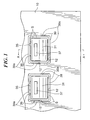
- FIG. 1 is a fragmentary plan view of a panel operator structure according to one embodiment of this invention.
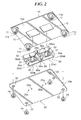
- FIG. 2 is an exploded perspective view of the panel operator structure
- FIG. 3 is a perspective view of one operator unit of the panel operator structure
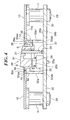
- FIG. 4 is a section view taken along line A-A in FIG. 1 ;
- FIG. 5A is a plan view showing a modification of the operator unit
- FIG. 5B is a plan view showing another modification of the operator unit
- FIG. 6 is an exploded perspective view showing an example of a panel operator structure of prior art electronic equipment.
- FIG. 7 is a vertical section view of an operator unit of the prior art panel operator structure.
- FIG. 1 shows in plan view a panel operator structure according to one embodiment of this invention.
- This panel operator structure can be applied to various electronic equipment such as a mixer apparatus and other sound apparatuses.
- FIG. 2 shows the panel operator structure in an exploded schematic view.
- the panel operator structure includes a base plate 20 on which an operation panel 10 is disposed in a stacking fashion in parallel thereto.
- Operator units 30 are disposed between the base plate 20 and the operation panel 10. It should be noted that only the two operator units 30 are shown, but a greater number of operator units 30 can be provided.
- the two operator units 30 in FIG. 2 are disposed in a state in which they remain coupled to each other, but may be provided separately from each other as described later.
- FIG. 3 is a perspective view of one of the operator units 30, and FIG. 4 is a section view taken along line A-A in FIG. 1 .
- the side close to the operation panel 10 with respect to the base plate 20 is hereinafter referred to as the upper side.
- the upward and downward direction in the panel operator structure corresponds to the upward and downward direction in FIG. 4 .
- the operation panel is not necessarily positioned on the upper side of electronic equipment to which the panel operator structure is applied, but can be positioned on a lateral side or a lower side thereof.
- the base plate 20 has its four corners in each of which a panel mounting hole 22 is formed. Each panel mounting hole 22 may be an unloaded hole.
- a plurality of pairs of a switch 25 and an LED 29, each pair corresponding to one of the operator units 30, are disposed on an upper surface 20a of the base plate 20.
- the switch 25 has a terminal 25a thereof exposed to a rear surface 20b of the base plate 20 (refer to FIGS. 2 and 4 ), and includes a driven portion 25b thereof adapted to be moved when depressed.
- the switches 25 and the LEDs 29 can be disposed in an arbitrary manner so long as they can be fixed to the base plate 20 before the operation panel 10 is mounted to the base plate 20.
- the operation panel 10 is made of metal such as a steel plate. As shown in FIG. 2 , studs 11 are provided by welding or the like to four corners of a rear surface 10a of the operation panel 10. Each stud 11 is formed with a self-tapping pilot hole 11a.
- the operation panel 10 is formed with operator unit insertion holes 12 through each of which a corresponding one of the operator units 30 can be inserted.
- the two operator units 30 are made of resin and molded integrally with each other. As shown in FIG. 2 , these operator units 30 are coupled together at their coupling portions 38 in each of which a thin thickness portion 38a is formed. The operator units 30 can be separated into individual pieces by cutting them at cut portions 38aa of the thin thickness portions 38a. One of the operator units 30 cut into two pieces at the cut portions 38aa is shown in FIG. 3 .
- a twin-type operator unit comprised of two operator units 30 has been described by way of example.
- a multi-coupled structure can be adopted, in which three or more operator units are coupled in line.
- another multi-coupled structure can be adopted, in which operator units 30 are coupled in a matrix fashion, i.e., coupled in the horizontal direction using the coupling portions 38 and in the vertical direction using coupling portions similar to the coupling portions 38.
- Each multi-coupled structure can be configured such that the operator units 30 are separated into groups each including a predetermined number of operator units or separated into individual pieces, and then mounted on the base plate 20 or the operation panel 10.
- each operator unit 30 includes a casing 32 to which a key top 31 subjected to a depression operation is connected via a hinge 35.
- the casing 32 has four wall portions 32a that are arranged in a rectangular shape as a whole as seen in plan view.
- the key top 31 is connected for vertical pivotal motion via the hinge 35 to the inner side of one of the wall portions 32a (hereinafter referred to as the wall portion 32a1, where required).
- each hinge 35 is disposed between the base plate 20 and the operation panel 10 (refer to FIG. 4 ) .
- the hinge 35 can only slightly be seen from above through a gap S between the key top 31 and frame portions 39 (described later), as shown in FIG. 1 .
- the key top 31 of each operator unit 30 has a lower portion thereof integrally formed with an actuator 36.
- the key top 31 When subjected to a depression/release operation, the key top 31 is vertically pivoted relative to the casing 32 and the actuator 36 is vertically pivoted together with the key top 31.
- a lower end of the actuator 36 When the key top 31 is in non-depressed state, a lower end of the actuator 36 is positioned near a driven portion 25b of the switch 25.
- the driven portion 25b of the switch 25 is depressed by the actuator 36, and the switch 25 is turned on.
- the switch 25 is used, for example, for the setting of a predetermined function.
- the switch 25 must be configured to be driven by the actuator 36 so as to be turned on/off, for example, but is not limited in its construction and function to the illustrated one.
- each operator unit 30 a translucent portion 37 is provided closer to the wall portion 32a1 than to the actuator 36.
- the translucent portion 37 is formed by a transparent resin.
- portions of the operator unit 30 other than the translucent portion 37 are formed by an opaque resin.
- the operator unit 30 is integrally molded using two-color molding in which the transparent resin and the opaque resin are used.
- the translucent portion 37 has an upper end thereof disposed in flush with the upper surface of the key top 31 so as to be exposed to the outside (see, FIGS. 1 and 3 ).
- a lower end of the translucent portion 37 of each operator unit 30 is positioned near the LED 29.
- the LED 29 is always in a light emission state.
- the LED 29 can be made in a light emission/extinction state in response to the switch 25 being turned on/off upon depression/release of the key top 31. Light emitted from the LED 29 passes through the translucent portion 37 and is visually recognized by a user.
- the four wall portions 32a have upper parts thereof each formed with a stepped portion.
- the upper part of each wall portion 32a includes a ridge-like frame portion 39 located inside an upper end 32aa of the wall portion 32a and extending beyond the upper end 32aa.
- the frame portions 39 are continuously connected together to describe a rectangular shape as seen in plan view, and the key top 31 is positioned inside the frame portions 39 with a gap S of a predetermined width therebetween.
- the frame portions 39 of each operation unit 30 are fitted into a corresponding one of the operator unit insertion holes 12 formed in the operation panel 10. Specifically, outer side surfaces 39a of the frame portions 39 are engaged along the entire circumference thereof with the insertion hole 12. As a result, the position of the operator unit 30 relative to the operator unit insertion hole 12 as viewed in the horizontal direction (parallel to the operation panel 10 and the base plate 20) is restricted.
- the frame portions 39 (more specifically, the outer side surfaces 39a thereof) cooperate with the insertion hole 12 to function as a "horizontal position restricting unit” that restricts the position of the operator unit 30 in the horizontal direction.
- each operation unit 30 Furthermore, the upper and lower ends 32aa, 32ab of the wall portions 32a of each operation unit 30 are in abutment with the rear surface 10a of the operation panel 10 and the upper surface 20a of the base plate 20, respectively. As a result, the vertical position of each operator unit 30 relative to the base plate 20 and the operation panel 10 is restricted. Thus, in the state where the operator units 30 are assembled between the operation panel 10 and the base plate 20 as shown in FIG. 4 , the operator units 30 can be fixed in position, without the need of using additional fixing means such as fastening screws and the like.
- the upper and lower ends 32aa, 32ab of the wall portions 32a of each operator unit 30 cooperate with the rear surface 10a of the operation panel 10 and the upper surface 20a of the base plate 20 to function as a "vertical position restricting unit” that restricts the position of the operator unit 30 in the vertical direction (normal to the base plate 20).
- the operator units 30 and the operation panel 10 are assembled onto the base plate 20, as described below.
- the base plate 20 is mounted on the operation panel 10 such that the upper surface 20a of the base plate 20 covers the rear surface l0a of the operational panel 10 and the panel mounting holes 22 are aligned with the pilot holes 11a formed in the studs 11.
- screws 28 are threadedly engaged with the pilot holes 11a of the studs 11 from the side of the rear surface 20b of the base plate 20, whereby the operation panel 10 is fixed to the base plate 20 in parallel therewith.
- the lower ends 32ab of the four wall portions 32a of each operator unit 30 are brought in abutment with the upper surface 20a of the base plate 20 and surround the switch 25 and the LED 29 associated therewith.
- the dimension between the upper and lower ends 32aa, 32ab of the wall portions 32a is set to a value that is equal to or slightly less than the length of the studs 11.
- the distance between the operation panel 10 and the base plate 20 is substantially determined by the length of the studs 11.
- the position of each operator unit 30 in the direction parallel to the base plate 20 is restricted by the frame portions 39 of the operator unit 30 being fitted into the insertion hole 12 of the operation panel 10.
- the positional relation between the operator unit 30 and the insertion hole 12 is not affected by a deviation in relative position between the operation panel 10 and the base plate 20 and by the degree of positional accuracy of the insertion hole 12 formed in the operator panel 10.
- the operation panel 10 is made of metal and formed with a number of the insertion holes 12 whose positional accuracy is not quite high, a deviation of relative position between the operator units 30 (more specifically, the casing 32 thereof) and the insertion holes 12 is not caused.
- each operator unit 30 and the corresponding operator unit insertion hole 12 makes it possible to prevent the key top 31, when operated, from being brought in contact with the insertion hole 12.
- operation failure, degraded operation feeling or the like can be suppressed from occurring due to contact between any of the key tops and the corresponding insertion hole.
- the operation of the key tops 31 is not affected, even if the operation panel 10 is made of metal and any of the insertion holes 12 has some burrs.
- the operator units 30 assembled between the operation panel 10 and the base plate 20 are retained therebetween so as to be restricted in vertical position, making it unnecessary to provide the base plate 20 with holes and the like used for mounting the operator units 30, and therefore, pattern wiring inhibition regions which are ordinarily provided around the operator unit mounting holes can be reduced or eliminated and hence the efficiency of pattern wiring can be improved.
- the gap S with a constant width can be formed between the key top 31 and the frame portions 39 of the operator unit 30 over the entire circumference of the key top, making it possible to improve external appearance.
- the operator unit 30 can be formed into a thin-shape with ease, to thereby reduce the degree of projection of the operator unit from the operation panel 10.
- the key top 31 of this embodiment slightly projects from the operation panel 10, the key top 31 can be designed so as to be in flush with or to be located lower than the surface of the operation panel 10. Since the hinge 35 is disposed lower than the operation panel 10, the hinge 35 is not required to be extended from the upper end of the frame portion 39 associated therewith.
- each operator unit 30 can be continuously formed over the entire circumference thereof without any disconnection and can be fitted at their entire circumference into the insertion hole 12, whereby the function of restricting the horizontal position of the operator unit 30 can be achieved satisfactorily.
- each operation unit 30 is completely covered by the wall portions 32a from four directions, and the wall portions 32a are made of opaque resin. As a result, light emitted from the LED 29 is prevented from leaking to the outside, and the depressed state of each operator unit 30 can be visually recognized with reliability based on light passing through the translucent portion 37 of the operator unit 30.
- each operator unit 30 of this embodiment is configured for pivotal motion in the direction perpendicular to the base plate 20, but this is not limitative.
- the present invention can be applied to any operator units 30 so long as they are configured to be pivoted relative to the base plate 20 in a direction other than the horizontal direction.
- each key top 31 can be configured for connection to the casing 32 via two hinges 35 between which the key top 31 is interposed for pivotal motion in the vertical direction parallel to the casing 32.
- the key top 31 can be connected to the casing 32 via three or more appropriately spaced hinges (not shown) or via a hinge (not shown) provided along the entire circumference of the key top 31.
- each operator unit 30 of this embodiment are continuously connected together, without any disconnection, to extend along the entire circumference thereof. Since the frame portions are only required to restrict the horizontal position of the casing 32, there may be a disconnection between the frame portions 39.
- the frame portions may be formed into a shape other than a frame-like shape. Plural portions adapted to be engaged with the operator unit insertion hole 12 and functioning to restrict a motion of the casing 32 in four directions can be fixedly provided relative to the casing 32.
- the frame portions 39 can be formed into a circular or ellipsoid shape as well as a quadrangular or rectangular shape as viewed in plan. In the case of frame portions formed into a circular shape, it is enough to provide at least three spaced restriction portions in order to restrict the horizontal motion of the casing 32.
- an operator unit according to another modification shown in plan view in FIG. 5B can be adopted.
- the hinge 35 is extended from the upper end 32aa of the wall portion 32a1 of the casing 32 and provided at a vertical position which is the same as or higher than that of the upper end 32aa.
- each operator unit 30 can be formed by elastomer in the above-described embodiment.
- both the key top 31 and the hinge 35 can be formed by elastomer. Even in such arrangements, there is no fear that the key top 31 is made in contact with the operator unit insertion hole 12, and therefore, the advantage of improving operation feeling can be attained with ease.
Landscapes
- Rotary Switch, Piano Key Switch, And Lever Switch (AREA)
- Switch Cases, Indication, And Locking (AREA)
Abstract
Description
- The present invention relates to a panel operator structure for electronic equipment such as sound equipment.
- Conventionally, some electronic equipment such as sound equipment includes an operation panel provided with a number of operator units. An operation panel of this type has a base plate thereof mounted with various switches that are each adapted to be turned on/off for function settings of the electronic equipment when a corresponding one of the operator units is operated.
-
FIG. 6 is an exploded schematic view showing an example of a prior art panel operator structure for electronic equipment, andFIG. 7 is a vertical section view of an operator unit of the prior art panel operator structure. - As shown in
FIGS. 6 and7 , the panel operator structure includes a number of operator units (only one of which is shown byreference numeral 130 for simplified illustration) fixed on abase plate 120 and anoperation panel 110 disposed in an overlapping relation and parallel with thebase plate 120. - The
base plate 120 has its four corners where there are formed analignment hole 121, anelongated hole 124, and unloadedholes unit mounting holes 126 and two operatorunit locating holes 127 are formed in thebase plate 120, and switches (only one of which is shown at 125) are disposed on thebase plate 120. - As shown in
FIG. 7 , theoperator unit 130 includes acasing 132 to which akey top 131 as a depression-operated portion is connected via ahinge 135. Anactuator 136 is formed integrally with a lower portion, as seen inFIG. 7 , of thekey top 131. Thekey top 131 is, when depressed or released, pivoted relative to thecasing 132 in the vertical direction inFIG. 7 . Theswitch 125 is turned on when depressed by theactuator 136. - The
operator unit 130 is formed with threemounting pawls 133 and two locatingpins 134 and fixed in position to thebase plate 120 by thepawls 133 and the locatingpins 134 inserted into the operatorunit mounting holes 126 and the operatorunit locating holes 127 of thebase plate 120 for engagement therewith. - The
operation panel 110 has its four corners formed withstuds 111 in each of which a self-tapping pilot hole, not shown, is formed. To fix theoperation panel 110 to thebase plate 120,screws 128 are threadedly engaged with the self-tapping pilot holes of thestuds 111 from the rear side of thebase plate 120, with thestuds 111 of theoperation panel 110 aligned with thealignment hole 121, theelongated hole 124, and theunloaded holes base plate 120 on which theoperator unit 130 has been mounted. - The
operation panel 110 is formed with operatorunit insertion holes 112 into which theoperator units 130 are inserted. In a state where theoperation panel 110 is fixed to thebase plate 120, thekey top 131 of eachoperator unit 130 is disposed within theinsertion hole 112 with a clearance therebetween, as shown inFIG. 7 . Provided that theoperator unit 130 is disposed in position within theinsertion hole 112, thekey top 131 is kept out of contact with theinsertion hole 112 when depressed or released. - In the prior art panel operator structure shown in
FIGS. 6 and7 , the horizontal positional relation between theoperation panel 110 and thebase plate 120 is determined by the positional relation between thealignment hole 121 and a corresponding one of the pilot holes of thestuds 111. - In the case of the
operation panel 110 made of metal, thestuds 111 are ordinarily welded or the like to theoperation panel 110, and weld positions of thestuds 111 can vary. In addition to a variation in the weld positions of thestuds 111, there can be variations in shape of thestuds 111 and position and shape of the pilot holes, resulting in a deviation in the positions of thestuds 111 on theoperation panel 110, which causes a deviation in the positional relation between theoperation panel 110 and thebase plate 120. - The horizontal positional relation between the
operator units 130 and the operatorunit insertion holes 112 of theoperation panel 110 is affected not only by the above-described positional deviation between theoperation panel 110 and thebase plate 120, but also by the mounting accuracy of theoperator units 130 on thebase plate 120 since, as described above, theoperator units 130 are fixed on thebase plate 120. Furthermore, the positional relation between theoperator units 130 and theinsertion holes 112 is affected by the accuracy of formation of theinsertion holes 112 in theoperation panel 110. - Thus, a proper positional relation between the
operator units 130 and the operatorunit insertion holes 112 cannot sometimes be attained. In that case, the clearance between theinsertion hole 112 and thekey top 131 increases on one side of the key top, but decreases on the other side thereof. As a result, thekey top 131 can be in contact with theinsertion hole 112 when depressed or released. Such contact can result in operation failure, degraded operation feeling or the like. - For EMI countermeasure, rigidity maintenance, reduction in die cost or the like, a large-sized mixer apparatus in particular is often demanded to be made of metal (a steel plate or the like), not of resin. Moreover, such a mixer apparatus or the like is provided with a number of
operator units 130. Therefore, theoperation panel 110 becomes large in size, and a number of operatorunit insertion holes 112 must be formed. The accuracy of forming theinsertion holes 112 in theoperation panel 110 is liable to be worsened. As a result, it is further difficult to attain a proper positional relation between theoperator units 130 and the operatorunit insertion holes 112 and between theoperator panel 110 and abase plate 120. - Conventionally, therefore, the operation panel and the base plate formed with no locating holes are sometimes positioned by a personnel based on a visual checking to have a proper positional relation to each other. Then, the operation panel is fixed to the base plate by the personnel. However, such work is cumbersome.
- Pattern wiring inhibition regions where formation of wiring patterns is inhibited are provided in the vicinity of operator unit mounting holes formed in the base plate. Thus, the greater the number of the operator units that must be provided, the much worsened the efficiency of pattern wiring will be.
- Meanwhile, in the case of an operation panel made of resin as disclosed in
Japanese Laid-open Patent Publication No. 06-267373 - On the other hand, in a case where such mounting portions are provided by welding or the like to an operation panel made of metal, the accuracy of providing the mounting portions becomes low, and therefore, a proper clearance cannot sometimes be provided between operator unit insertion holes and key tops, which poses a problem.
- The present invention provides a panel operator structure for electronic equipment, in which a key top of each operator unit is prevented from being in contact with a corresponding one of operator unit insertion holes.
- According to the present invention, there is provided a panel operator structure for electronic equipment, comprising a plurality of operator units, a base plate, an operation panel formed with fitting holes to each of which a corresponding one of the plurality of operator units is fitted, the operation panel being disposed in parallel to the base plate, and switches each having a driven portion, the switches being disposed on a side of the base plate close to the operation panel so as to correspond to the plurality of operator units, respectively, wherein each of the plurality of operator units includes a casing, a key top adapted to be pivoted relative to the casing in a direction not parallel to the base plate when subjected to a depression/release operation, and an actuator adapted to be moved in unison with the key top to depress and drive the driven portion of a corresponding one of the switches, and wherein the casing of each of the plurality of operator units is fixedly provided with a horizontal position restricting unit fitted in a corresponding one of the fitting holes formed in the operation panel, the horizontal position restricting unit being adapted to restrict a position of the operator unit in a direction parallel to the base plate.
- With the panel operator structure of this invention, the operator units can individually be disposed in position relative to the operator unit insertion holes, making it possible to prevent the key top of each operator unit from being made in contact with the corresponding operator unit insertion hole when the key top is operated.
- The key top of each of the plurality of operator units can be configured for pivotal motion in a corresponding one of the fitting holes in a position inside the horizontal position restricting unit.
- In that case, the key top when operated can be prevented from being brought in contact with the operator insertion hole with reliability.
- The casing of each of the plurality of operator units can be fixedly provided with a vertical position restricting unit, the vertical position restricting unit being interposed between the operation panel and the base plate and adapted to restrict a position of the operator unit in a direction perpendicular to the base plate.
- In that case, the base plate is not required to be provided with operator unit mounting holes, making it possible to eliminate or reduce wiring pattern inhibition regions which are ordinarily provided around the mounting holes.
- The key top of each of the plurality of operator units can be connected for pivotal motion to the casing via a hinge, and the hinge can be interposed between the operation panel and the base plate.
- In that case, a gap with a constant width can be formed between the horizontal position restricting unit and the key top of each operator unit over the entire circumference of the key top, making it possible to improve external appearance.
- The panel operator structure can include light emitting units disposed on a surface of the base plate on a side close to the operation panel so as to each correspond to an associated one of the plurality of operator units, and the key top of each of the plurality of operator units can be provided with a translucent portion through which light emitted from a corresponding one of the light emitting units passes, and the casing of each of the plurality of operator units can be made of an opaque material and can include wall portions thereof adapted to be in contact with a surface of the base plate on a side close to the operation panel and adapted to surround the light emitting unit and the switch.
- In that case, light from the light emitting units can be prevented from leaking to the outside, making it possible for a depressed state of the operator units to be visually recognized by a user with reliability.
- Further features of the present invention will become apparent from the following description of an exemplary embodiment with reference to the attached drawings.
-
FIG. 1 is a fragmentary plan view of a panel operator structure according to one embodiment of this invention; -
FIG. 2 is an exploded perspective view of the panel operator structure; -
FIG. 3 is a perspective view of one operator unit of the panel operator structure; -
FIG. 4 is a section view taken along line A-A inFIG. 1 ; -
FIG. 5A is a plan view showing a modification of the operator unit; -
FIG. 5B is a plan view showing another modification of the operator unit; -
FIG. 6 is an exploded perspective view showing an example of a panel operator structure of prior art electronic equipment; and -
FIG. 7 is a vertical section view of an operator unit of the prior art panel operator structure. - The present invention will now be described in detail below with reference to the drawings showing a preferred embodiment thereof.
-
FIG. 1 shows in plan view a panel operator structure according to one embodiment of this invention. This panel operator structure can be applied to various electronic equipment such as a mixer apparatus and other sound apparatuses. -
FIG. 2 shows the panel operator structure in an exploded schematic view. The panel operator structure includes abase plate 20 on which anoperation panel 10 is disposed in a stacking fashion in parallel thereto.Operator units 30 are disposed between thebase plate 20 and theoperation panel 10. It should be noted that only the twooperator units 30 are shown, but a greater number ofoperator units 30 can be provided. The twooperator units 30 inFIG. 2 are disposed in a state in which they remain coupled to each other, but may be provided separately from each other as described later. -
FIG. 3 is a perspective view of one of theoperator units 30, andFIG. 4 is a section view taken along line A-A inFIG. 1 . For convenience of explanation, the side close to theoperation panel 10 with respect to thebase plate 20 is hereinafter referred to as the upper side. In other words, the upward and downward direction in the panel operator structure corresponds to the upward and downward direction inFIG. 4 . To be noted, the operation panel is not necessarily positioned on the upper side of electronic equipment to which the panel operator structure is applied, but can be positioned on a lateral side or a lower side thereof. - As shown in
FIG. 2 , thebase plate 20 has its four corners in each of which apanel mounting hole 22 is formed. Eachpanel mounting hole 22 may be an unloaded hole. As shown inFIG. 4 , a plurality of pairs of aswitch 25 and anLED 29, each pair corresponding to one of theoperator units 30, are disposed on anupper surface 20a of thebase plate 20. Theswitch 25 has a terminal 25a thereof exposed to arear surface 20b of the base plate 20 (refer toFIGS. 2 and4 ), and includes a drivenportion 25b thereof adapted to be moved when depressed. Theswitches 25 and theLEDs 29 can be disposed in an arbitrary manner so long as they can be fixed to thebase plate 20 before theoperation panel 10 is mounted to thebase plate 20. - The
operation panel 10 is made of metal such as a steel plate. As shown inFIG. 2 ,studs 11 are provided by welding or the like to four corners of arear surface 10a of theoperation panel 10. Eachstud 11 is formed with a self-tappingpilot hole 11a. Theoperation panel 10 is formed with operator unit insertion holes 12 through each of which a corresponding one of theoperator units 30 can be inserted. - The two
operator units 30 are made of resin and molded integrally with each other. As shown inFIG. 2 , theseoperator units 30 are coupled together at theircoupling portions 38 in each of which athin thickness portion 38a is formed. Theoperator units 30 can be separated into individual pieces by cutting them at cut portions 38aa of thethin thickness portions 38a. One of theoperator units 30 cut into two pieces at the cut portions 38aa is shown inFIG. 3 . - In the above, a twin-type operator unit comprised of two
operator units 30 has been described by way of example. A multi-coupled structure can be adopted, in which three or more operator units are coupled in line. Alternatively, another multi-coupled structure can be adopted, in whichoperator units 30 are coupled in a matrix fashion, i.e., coupled in the horizontal direction using thecoupling portions 38 and in the vertical direction using coupling portions similar to thecoupling portions 38. Each multi-coupled structure can be configured such that theoperator units 30 are separated into groups each including a predetermined number of operator units or separated into individual pieces, and then mounted on thebase plate 20 or theoperation panel 10. - As shown in
FIG. 4 , eachoperator unit 30 includes acasing 32 to which a key top 31 subjected to a depression operation is connected via ahinge 35. Thecasing 32 has fourwall portions 32a that are arranged in a rectangular shape as a whole as seen in plan view. The key top 31 is connected for vertical pivotal motion via thehinge 35 to the inner side of one of thewall portions 32a (hereinafter referred to as the wall portion 32a1, where required). In a state where theoperator units 30 and theoperation panel 10 are assembled together, each hinge 35 is disposed between thebase plate 20 and the operation panel 10 (refer toFIG. 4 ) . Thus, thehinge 35 can only slightly be seen from above through a gap S between the key top 31 and frame portions 39 (described later), as shown inFIG. 1 . - As shown in
FIG. 4 , thekey top 31 of eachoperator unit 30 has a lower portion thereof integrally formed with anactuator 36. When subjected to a depression/release operation, the key top 31 is vertically pivoted relative to thecasing 32 and theactuator 36 is vertically pivoted together with thekey top 31. When the key top 31 is in non-depressed state, a lower end of theactuator 36 is positioned near a drivenportion 25b of theswitch 25. When the key top 31 is depressed, the drivenportion 25b of theswitch 25 is depressed by theactuator 36, and theswitch 25 is turned on. Theswitch 25 is used, for example, for the setting of a predetermined function. Theswitch 25 must be configured to be driven by theactuator 36 so as to be turned on/off, for example, but is not limited in its construction and function to the illustrated one. - In the
key top 31 of eachoperator unit 30, atranslucent portion 37 is provided closer to the wall portion 32a1 than to theactuator 36. Thetranslucent portion 37 is formed by a transparent resin. On the other hand, portions of theoperator unit 30 other than thetranslucent portion 37 are formed by an opaque resin. Thus, theoperator unit 30 is integrally molded using two-color molding in which the transparent resin and the opaque resin are used. - The
translucent portion 37 has an upper end thereof disposed in flush with the upper surface of the key top 31 so as to be exposed to the outside (see,FIGS. 1 and3 ). In a state that theoperator units 30 are assembled between theoperation panel 10 and thebase plate 20, a lower end of thetranslucent portion 37 of eachoperator unit 30 is positioned near theLED 29. When the electronic equipment is in use, theLED 29 is always in a light emission state. Alternatively, theLED 29 can be made in a light emission/extinction state in response to theswitch 25 being turned on/off upon depression/release of thekey top 31. Light emitted from theLED 29 passes through thetranslucent portion 37 and is visually recognized by a user. - In the state that the
operator units 30 are assembled between theoperation panel 10 and thebase plate 20, lower ends 32ab of the fourwall portions 32a of eachoperator unit 30 are in abutment with theupper surface 20a of thebase plate 20 so as to surround theswitch 25 and theLED 29. Since thewall portions 32a are opaque, light emitted from theLED 29 is blocked by thewall portions 32a and prevented from leaking to the outside of theoperator unit 30, but can be visually recognized only from the side of the upper end of thetranslucent portion 37 of theoperator unit 30. - The four
wall portions 32a have upper parts thereof each formed with a stepped portion. Specifically, the upper part of eachwall portion 32a includes a ridge-like frame portion 39 located inside an upper end 32aa of thewall portion 32a and extending beyond the upper end 32aa. As shown inFIG. 1 , theframe portions 39 are continuously connected together to describe a rectangular shape as seen in plan view, and the key top 31 is positioned inside theframe portions 39 with a gap S of a predetermined width therebetween. - In the state that the
operator units 30 are assembled between theoperation panel 10 and thebase plate 20, theframe portions 39 of eachoperation unit 30 are fitted into a corresponding one of the operator unit insertion holes 12 formed in theoperation panel 10. Specifically,outer side surfaces 39a of theframe portions 39 are engaged along the entire circumference thereof with theinsertion hole 12. As a result, the position of theoperator unit 30 relative to the operatorunit insertion hole 12 as viewed in the horizontal direction (parallel to theoperation panel 10 and the base plate 20) is restricted. Thus, the frame portions 39 (more specifically, theouter side surfaces 39a thereof) cooperate with theinsertion hole 12 to function as a "horizontal position restricting unit" that restricts the position of theoperator unit 30 in the horizontal direction. - Furthermore, the upper and lower ends 32aa, 32ab of the
wall portions 32a of eachoperation unit 30 are in abutment with therear surface 10a of theoperation panel 10 and theupper surface 20a of thebase plate 20, respectively. As a result, the vertical position of eachoperator unit 30 relative to thebase plate 20 and theoperation panel 10 is restricted. Thus, in the state where theoperator units 30 are assembled between theoperation panel 10 and thebase plate 20 as shown inFIG. 4 , theoperator units 30 can be fixed in position, without the need of using additional fixing means such as fastening screws and the like. - Thus, the upper and lower ends 32aa, 32ab of the
wall portions 32a of eachoperator unit 30 cooperate with therear surface 10a of theoperation panel 10 and theupper surface 20a of thebase plate 20 to function as a "vertical position restricting unit" that restricts the position of theoperator unit 30 in the vertical direction (normal to the base plate 20). - The
operator units 30 and theoperation panel 10 are assembled onto thebase plate 20, as described below. - First, all the
switches 25 and theLEDs 29 are fixedly disposed on thebase plate 20. For easy understanding of the following description, the reader is requested to turn the sheet ofFIG. 2 upside down. After theoperation panel 10 is reversed, theoperator units 30 are fitted into the operator unit insertion holes 12 from therear surface 10a side of theoperation panel 10. At this time, the upper ends 32aa of thewall portions 32a of eachoperator unit 30 are brought in abutment with therear surface 10a of theoperation panel 10, which facilitates the subsequent assembly operations since theoperator units 30 can be kept unmoved even if theoperation panel 10 is somewhat inclined. - Next; the
base plate 20 is mounted on theoperation panel 10 such that theupper surface 20a of thebase plate 20 covers the rear surface l0a of theoperational panel 10 and thepanel mounting holes 22 are aligned with thepilot holes 11a formed in thestuds 11. Subsequently, screws 28 are threadedly engaged with thepilot holes 11a of thestuds 11 from the side of therear surface 20b of thebase plate 20, whereby theoperation panel 10 is fixed to thebase plate 20 in parallel therewith. At the same time, the lower ends 32ab of the fourwall portions 32a of eachoperator unit 30 are brought in abutment with theupper surface 20a of thebase plate 20 and surround theswitch 25 and theLED 29 associated therewith. - The dimension between the upper and lower ends 32aa, 32ab of the
wall portions 32a is set to a value that is equal to or slightly less than the length of thestuds 11. Thus, the distance between theoperation panel 10 and thebase plate 20 is substantially determined by the length of thestuds 11. - In the above-described arrangement, when the
key top 31 of any of theoperator units 30 is depressed or released, the key top 31 is vertically pivoted within theframe portions 39 of the operator unit, without being in contact with the operatorunit insertion hole 12. - . According to this embodiment, the position of each
operator unit 30 in the direction parallel to thebase plate 20 is restricted by theframe portions 39 of theoperator unit 30 being fitted into theinsertion hole 12 of theoperation panel 10. Thus, the positional relation between theoperator unit 30 and theinsertion hole 12 is not affected by a deviation in relative position between theoperation panel 10 and thebase plate 20 and by the degree of positional accuracy of theinsertion hole 12 formed in theoperator panel 10. In particular, even if theoperation panel 10 is made of metal and formed with a number of the insertion holes 12 whose positional accuracy is not quite high, a deviation of relative position between the operator units 30 (more specifically, thecasing 32 thereof) and the insertion holes 12 is not caused. - Thus, a proper positional relation can be attained between each
operator unit 30 and the corresponding operatorunit insertion hole 12, making it possible to prevent the key top 31, when operated, from being brought in contact with theinsertion hole 12. In addition, there is provided a gap S between the key top 31 and thecorresponding frame portions 39 of eachoperation unit 30, which ensures that the key top 31 is prevented from being in contact with theinsertion hole 12. As a result, operation failure, degraded operation feeling or the like can be suppressed from occurring due to contact between any of the key tops and the corresponding insertion hole. In particular, the operation of the key tops 31 is not affected, even if theoperation panel 10 is made of metal and any of the insertion holes 12 has some burrs. - The
operator units 30 assembled between theoperation panel 10 and thebase plate 20 are retained therebetween so as to be restricted in vertical position, making it unnecessary to provide thebase plate 20 with holes and the like used for mounting theoperator units 30, and therefore, pattern wiring inhibition regions which are ordinarily provided around the operator unit mounting holes can be reduced or eliminated and hence the efficiency of pattern wiring can be improved. - Since the
hinge 35 of eachoperator unit 30 is located between thebase plate 20 and theoperation panel 10, the gap S with a constant width can be formed between the key top 31 and theframe portions 39 of theoperator unit 30 over the entire circumference of the key top, making it possible to improve external appearance. In addition, theoperator unit 30 can be formed into a thin-shape with ease, to thereby reduce the degree of projection of the operator unit from theoperation panel 10. Although thekey top 31 of this embodiment slightly projects from theoperation panel 10, the key top 31 can be designed so as to be in flush with or to be located lower than the surface of theoperation panel 10. Since thehinge 35 is disposed lower than theoperation panel 10, thehinge 35 is not required to be extended from the upper end of theframe portion 39 associated therewith. As a result, theframe portions 39 of eachoperator unit 30 can be continuously formed over the entire circumference thereof without any disconnection and can be fitted at their entire circumference into theinsertion hole 12, whereby the function of restricting the horizontal position of theoperator unit 30 can be achieved satisfactorily. - Furthermore, the
LED 29 of eachoperation unit 30 is completely covered by thewall portions 32a from four directions, and thewall portions 32a are made of opaque resin. As a result, light emitted from theLED 29 is prevented from leaking to the outside, and the depressed state of eachoperator unit 30 can be visually recognized with reliability based on light passing through thetranslucent portion 37 of theoperator unit 30. - The
key top 31 of eachoperator unit 30 of this embodiment is configured for pivotal motion in the direction perpendicular to thebase plate 20, but this is not limitative. The present invention can be applied to anyoperator units 30 so long as they are configured to be pivoted relative to thebase plate 20 in a direction other than the horizontal direction. - As shown in
FIG. 5A in which an operator unit according to a modification of the above-described embodiment is shown in plan view, each key top 31 can be configured for connection to thecasing 32 via twohinges 35 between which the key top 31 is interposed for pivotal motion in the vertical direction parallel to thecasing 32. Alternatively, the key top 31 can be connected to thecasing 32 via three or more appropriately spaced hinges (not shown) or via a hinge (not shown) provided along the entire circumference of thekey top 31. - The frame portions of each
operator unit 30 of this embodiment are continuously connected together, without any disconnection, to extend along the entire circumference thereof. Since the frame portions are only required to restrict the horizontal position of thecasing 32, there may be a disconnection between theframe portions 39. The frame portions may be formed into a shape other than a frame-like shape. Plural portions adapted to be engaged with the operatorunit insertion hole 12 and functioning to restrict a motion of thecasing 32 in four directions can be fixedly provided relative to thecasing 32. Theframe portions 39 can be formed into a circular or ellipsoid shape as well as a quadrangular or rectangular shape as viewed in plan. In the case of frame portions formed into a circular shape, it is enough to provide at least three spaced restriction portions in order to restrict the horizontal motion of thecasing 32. - Although the advantage achieved by the gap S with a constant width formed over the entire circumstance of the key top 31 cannot be attained, an operator unit according to another modification shown in plan view in
FIG. 5B can be adopted. In this operator unit, thehinge 35 is extended from the upper end 32aa of the wall portion 32a1 of thecasing 32 and provided at a vertical position which is the same as or higher than that of the upper end 32aa. Although a disconnection is formed in theframe portions 39 due to the presence of thehinge 35, the positional motion of thecasing 32 in four directions can be restricted without any trouble sinceframe portion parts 39b are provided even on the side of the wall portion 32a1. - It should be noted that the
key top 31 of eachoperator unit 30 can be formed by elastomer in the above-described embodiment. In the arrangement shown inFIG. 5A where the key top 31 is vertically pivoted in parallel to thecasing 32, both the key top 31 and thehinge 35 can be formed by elastomer. Even in such arrangements, there is no fear that the key top 31 is made in contact with the operatorunit insertion hole 12, and therefore, the advantage of improving operation feeling can be attained with ease.
Claims (5)
- A panel operator structure for electronic equipment, comprising:a plurality of operator units;a base plate;an operation panel formed with fitting holes to each of which a corresponding one of the plurality of operator units is fitted, said operation panel being disposed in parallel to said base plate; andswitches each having a driven portion, said switches being disposed on a side of said base plate close to said operation panel so as to correspond to the plurality of operator units, respectively,wherein each of the plurality of operator units includes a casing, a key top adapted to be pivoted relative to the casing in a direction not parallel to said base plate when subjected to a depression/release operation, and an actuator adapted to be moved in unison with the key top to depress and drive the driven portion of a corresponding one of the switches, and
wherein the casing of each of the plurality of operator units is fixedly provided with a horizontal position restricting unit fitted in a corresponding one of the fitting holes formed in said operation panel, said horizontal position restricting unit being adapted to restrict a position of the operator unit in a direction parallel to said base plate. - The panel operator structure according to claim 1, wherein the key top of each of the plurality of operator units is configured for pivotal motion in a corresponding one of the fitting holes in a position inside the horizontal position restricting unit.
- The panel operator structure according to claim 1, wherein the casing of each of the plurality of operator units is fixedly provided with a vertical position restricting unit, said vertical position restricting unit being interposed between said operation panel and said base plate and adapted to restrict a position of the operator unit in a direction perpendicular to said base plate.
- The panel operator structure according to claim 1, wherein the key top of each of the plurality of operator units is connected for pivotal motion to the casing via a hinge, and the hinge is interposed between said operation panel and said base plate.
- The panel operator structure according to claim 1, including:light emitting units disposed on a surface of said base plate on a side close to said operation panel so as to each correspond to an associated one-of the plurality of operator units,wherein the key top of each of the plurality of operator units is provided with a translucent portion through which light emitted from a corresponding one of the light emitting units passes, and
wherein the casing of each of the plurality of operator units is made of an opaque material and includes wall portions thereof adapted to be in contact with a surface of said base plate on a side close to said operation panel and adapted to surround the light emitting unit and the switch.
Applications Claiming Priority (1)
| Application Number | Priority Date | Filing Date | Title |
|---|---|---|---|
| JP2006342772A JP2008153169A (en) | 2006-12-20 | 2006-12-20 | Panel operating element structure of electronic equipment |
Publications (2)
| Publication Number | Publication Date |
|---|---|
| EP1936647A2 true EP1936647A2 (en) | 2008-06-25 |
| EP1936647A3 EP1936647A3 (en) | 2009-12-09 |
Family
ID=39204018
Family Applications (1)
| Application Number | Title | Priority Date | Filing Date |
|---|---|---|---|
| EP07122456A Withdrawn EP1936647A3 (en) | 2006-12-20 | 2007-12-06 | Panel operator structure for electronic equipment |
Country Status (4)
| Country | Link |
|---|---|
| US (1) | US7875819B2 (en) |
| EP (1) | EP1936647A3 (en) |
| JP (1) | JP2008153169A (en) |
| CN (1) | CN101236852B (en) |
Families Citing this family (9)
| Publication number | Priority date | Publication date | Assignee | Title |
|---|---|---|---|---|
| JP5292964B2 (en) * | 2008-07-16 | 2013-09-18 | ヤマハ株式会社 | Translucent operation unit |
| JP5317013B2 (en) * | 2009-03-16 | 2013-10-16 | ヤマハ株式会社 | Illuminated switch structure and push button |
| JP5493846B2 (en) * | 2009-12-28 | 2014-05-14 | ヤマハ株式会社 | Electrical device operation structure |
| JP5267477B2 (en) * | 2010-02-08 | 2013-08-21 | 住友電装株式会社 | Panel parts |
| CN102280288A (en) * | 2010-06-10 | 2011-12-14 | 鸿富锦精密工业(深圳)有限公司 | Key |
| EP2724434B1 (en) * | 2011-06-27 | 2020-03-04 | Labinal, LLC | Circuit breaker module with lighted faceplate display |
| JP5526116B2 (en) | 2011-12-19 | 2014-06-18 | 京セラドキュメントソリューションズ株式会社 | Button key structure of operation panel, operation panel and image forming apparatus |
| KR102712968B1 (en) * | 2022-02-25 | 2024-10-04 | 한국알프스 주식회사 | Bonding structure of knob type switch |
| CN115294831B (en) * | 2022-08-10 | 2023-09-15 | 中国船舶重工集团公司第七一九研究所 | Ship centralized control room operation training simulator |
Citations (1)
| Publication number | Priority date | Publication date | Assignee | Title |
|---|---|---|---|---|
| JPH06267373A (en) | 1993-03-11 | 1994-09-22 | Kansei Corp | Control knob structure of pushbutton switch |
Family Cites Families (19)
| Publication number | Priority date | Publication date | Assignee | Title |
|---|---|---|---|---|
| DE2933150C2 (en) * | 1979-08-16 | 1982-03-18 | Licentia Patent-Verwaltungs-Gmbh, 6000 Frankfurt | Keypad |
| JPS5817607B2 (en) * | 1980-02-26 | 1983-04-08 | 三洋電機株式会社 | coffee boiler |
| JPS6326893Y2 (en) * | 1980-08-13 | 1988-07-21 | ||
| US4742198A (en) * | 1986-12-09 | 1988-05-03 | Adams Elevator Equipment Co. | Push button assembly having an actuator subassembly fixed to the innerside of a face plate |
| JPS6420619A (en) * | 1987-07-15 | 1989-01-24 | Toshiba Corp | Electron beam aligner |
| JPH04259716A (en) * | 1991-02-13 | 1992-09-16 | Canon Inc | Operation button structure |
| ATE149735T1 (en) * | 1991-12-24 | 1997-03-15 | Inventio Ag | COMMAND AND NOTIFICATION DEVICE |
| GB2264393A (en) * | 1992-02-22 | 1993-08-25 | Mckechnie Uk Ltd | Keyboard |
| JP3951357B2 (en) * | 1997-05-27 | 2007-08-01 | 松下電器産業株式会社 | Rotating operation type electronic parts |
| JP2001086577A (en) * | 1999-09-14 | 2001-03-30 | Matsushita Electric Works Ltd | Control terminal for remote supervisory control system |
| JP2003217380A (en) * | 2002-01-17 | 2003-07-31 | Yazaki Corp | Switch illuminator |
| JP2003257283A (en) * | 2002-03-07 | 2003-09-12 | Yamaha Corp | Structure of operation element for operation panel |
| JP3838170B2 (en) * | 2002-07-08 | 2006-10-25 | 株式会社デンソー | Switch structure |
| CN1716485A (en) * | 2004-06-30 | 2006-01-04 | 上海乐金广电电子有限公司 | Press button device |
| CN1722329A (en) * | 2004-07-12 | 2006-01-18 | 上海乐金广电电子有限公司 | Mounting structure for volume control button |
| JP2006120378A (en) * | 2004-10-20 | 2006-05-11 | Funai Electric Co Ltd | Electronic apparatus |
| JP2006134657A (en) * | 2004-11-04 | 2006-05-25 | Funai Electric Co Ltd | Electrical and electronic device |
| CN2836211Y (en) * | 2004-12-27 | 2006-11-08 | 蒋宗坚 | Novel switch |
| JP2006260943A (en) * | 2005-03-17 | 2006-09-28 | Matsushita Electric Ind Co Ltd | Mounting structure of illuminated rotating electronic components |
-
2006
- 2006-12-20 JP JP2006342772A patent/JP2008153169A/en active Pending
-
2007
- 2007-12-06 EP EP07122456A patent/EP1936647A3/en not_active Withdrawn
- 2007-12-07 US US11/952,972 patent/US7875819B2/en not_active Expired - Fee Related
- 2007-12-20 CN CN200710302220XA patent/CN101236852B/en not_active Expired - Fee Related
Patent Citations (1)
| Publication number | Priority date | Publication date | Assignee | Title |
|---|---|---|---|---|
| JPH06267373A (en) | 1993-03-11 | 1994-09-22 | Kansei Corp | Control knob structure of pushbutton switch |
Also Published As
| Publication number | Publication date |
|---|---|
| JP2008153169A (en) | 2008-07-03 |
| EP1936647A3 (en) | 2009-12-09 |
| US20080173528A1 (en) | 2008-07-24 |
| CN101236852B (en) | 2010-08-11 |
| US7875819B2 (en) | 2011-01-25 |
| CN101236852A (en) | 2008-08-06 |
Similar Documents
| Publication | Publication Date | Title |
|---|---|---|
| US7875819B2 (en) | Panel operator structure for electronic equipment | |
| US9941074B2 (en) | Key structure and keyboard using the same | |
| US8693201B2 (en) | Switch structure, electronic component part installing structure, and electronic musical instrument including the same | |
| US8431852B2 (en) | Key switch device | |
| US10969831B2 (en) | Keyboard device and electronic apparatus | |
| US20240234052A1 (en) | Keyboard | |
| US20170194116A1 (en) | Backlit keyboard | |
| CN111081207A (en) | Keyboard musical instrument | |
| JP6669799B2 (en) | Keyboard device and electronic equipment | |
| JP2019215553A (en) | Display device | |
| TWI500061B (en) | Luminous keyboard device | |
| JP2011194576A (en) | Operation panel unit and electronic device | |
| CN101630603A (en) | Light-transmitting operator unit | |
| US11612074B2 (en) | Waterproofing structure and related electronic device | |
| JP2013097780A (en) | Light emission keyboard | |
| JP5142083B2 (en) | Electronic device and LED display structure thereof | |
| KR200442488Y1 (en) | Keypad assembly with seats with pressing protrusions on top of dome switch | |
| JP4973176B2 (en) | Panel controls for electronic equipment | |
| CN111670424B (en) | Peripheral device having at least one transparent key comprising a flexible film | |
| US20150107974A1 (en) | Keyboard equipped with light emitting structure | |
| JP2008153171A (en) | Panel operating element structure of electronic equipment | |
| US12451303B1 (en) | Key structure | |
| JP7540462B2 (en) | Switching device and electronic musical instrument | |
| JP5050844B2 (en) | Keyboard device | |
| JP4252509B2 (en) | Keyboard device |
Legal Events
| Date | Code | Title | Description |
|---|---|---|---|
| PUAI | Public reference made under article 153(3) epc to a published international application that has entered the european phase |
Free format text: ORIGINAL CODE: 0009012 |
|
| AK | Designated contracting states |
Kind code of ref document: A2 Designated state(s): AT BE BG CH CY CZ DE DK EE ES FI FR GB GR HU IE IS IT LI LT LU LV MC MT NL PL PT RO SE SI SK TR |
|
| AX | Request for extension of the european patent |
Extension state: AL BA HR MK RS |
|
| PUAL | Search report despatched |
Free format text: ORIGINAL CODE: 0009013 |
|
| AK | Designated contracting states |
Kind code of ref document: A3 Designated state(s): AT BE BG CH CY CZ DE DK EE ES FI FR GB GR HU IE IS IT LI LT LU LV MC MT NL PL PT RO SE SI SK TR |
|
| AX | Request for extension of the european patent |
Extension state: AL BA HR MK RS |
|
| RIC1 | Information provided on ipc code assigned before grant |
Ipc: H01H 21/24 20060101ALI20080402BHEP Ipc: H01H 13/705 20060101AFI20091102BHEP |
|
| 17P | Request for examination filed |
Effective date: 20100520 |
|
| AKX | Designation fees paid |
Designated state(s): AT BE BG CH CY CZ DE DK EE ES FI FR GB GR HU IE IS IT LI LT LU LV MC MT NL PL PT RO SE SI SK TR |
|
| 17Q | First examination report despatched |
Effective date: 20131016 |
|
| GRAP | Despatch of communication of intention to grant a patent |
Free format text: ORIGINAL CODE: EPIDOSNIGR1 |
|
| INTG | Intention to grant announced |
Effective date: 20161219 |
|
| STAA | Information on the status of an ep patent application or granted ep patent |
Free format text: STATUS: THE APPLICATION IS DEEMED TO BE WITHDRAWN |
|
| 18D | Application deemed to be withdrawn |
Effective date: 20170503 |